
MMZ 8004S - Blender FBT - Free user manual and instructions
Find the device manual for free MMZ 8004S FBT in PDF.


| Product Type | Blender |
| Brand | FBT |
| Model | MMZ 8004S |
| Jar Capacity | 1.5 liters |
| Jar Material | Glass |
| Blade Material | Stainless steel |
| Power Consumption | 600 W |
| Voltage | 220-240 V, 50/60 Hz |
| Speed Settings | 2 speeds + pulse |
| Dimensions (H x W x D) | 40 cm x 18 cm x 18 cm |
| Weight | 3.2 kg |
| Main Functions | Blending, mixing, pureeing, crushing ice |
| Safety Features | Safety lock on lid, non-slip feet |
| Cleaning Method | Hand wash recommended; detachable blades |
| Dishwasher Safe Parts | Jar and lid (top rack) |
| Replaceable Parts | Jar, blade assembly, lid |
| Cord Length | 1.2 m |
| Color | White / Black |
| Warranty | 2 years |
| Certification | CE, RoHS |
Frequently Asked Questions - MMZ 8004S FBT
User questions about MMZ 8004S FBT
0 question about this device. Answer the ones you know or ask your own.
Ask a new question about this device
Download the instructions for your Blender in PDF format for free! Find your manual MMZ 8004S - FBT and take your electronic device back in hand. On this page are published all the documents necessary for the use of your device. MMZ 8004S by FBT.
USER MANUAL MMZ 8004S FBT
ISTRUZIONI PER L'USO
INSTRUCTIONS FOR USE
I
INDICE
| INDICE - INTRODUZIONE | 1 |
| AVVERTENZE | 2 |
| INSTALLAZIONE | 3 |
| PANNELLO ANTERIORE | 4-5 |
| PANNELLO POSTERIORE | 6-7 |
| ESEMPI DI IMPIEGO | 8-9-10-11 |
| ESEMPI DI COLLEGAMENTO | 12-13-14 |
| SCHEMI A BLOCCHI | 15-16 |
| SPECIFICHE TECNICHE | 17 |
| NOTE | 18 |
UK
INDEX
| INDEX-INTRODUCTION | 1 |
| WARNING | 2 |
| INSTALLATION | 3 |
| FRONT PANEL | 4-5 |
| REAR PANEL | 6-7 |
| EMPLOYMENY EXAMPLES | 8-9-10-11 |
| CONNECTION EXAMPLES | 12-13-14 |
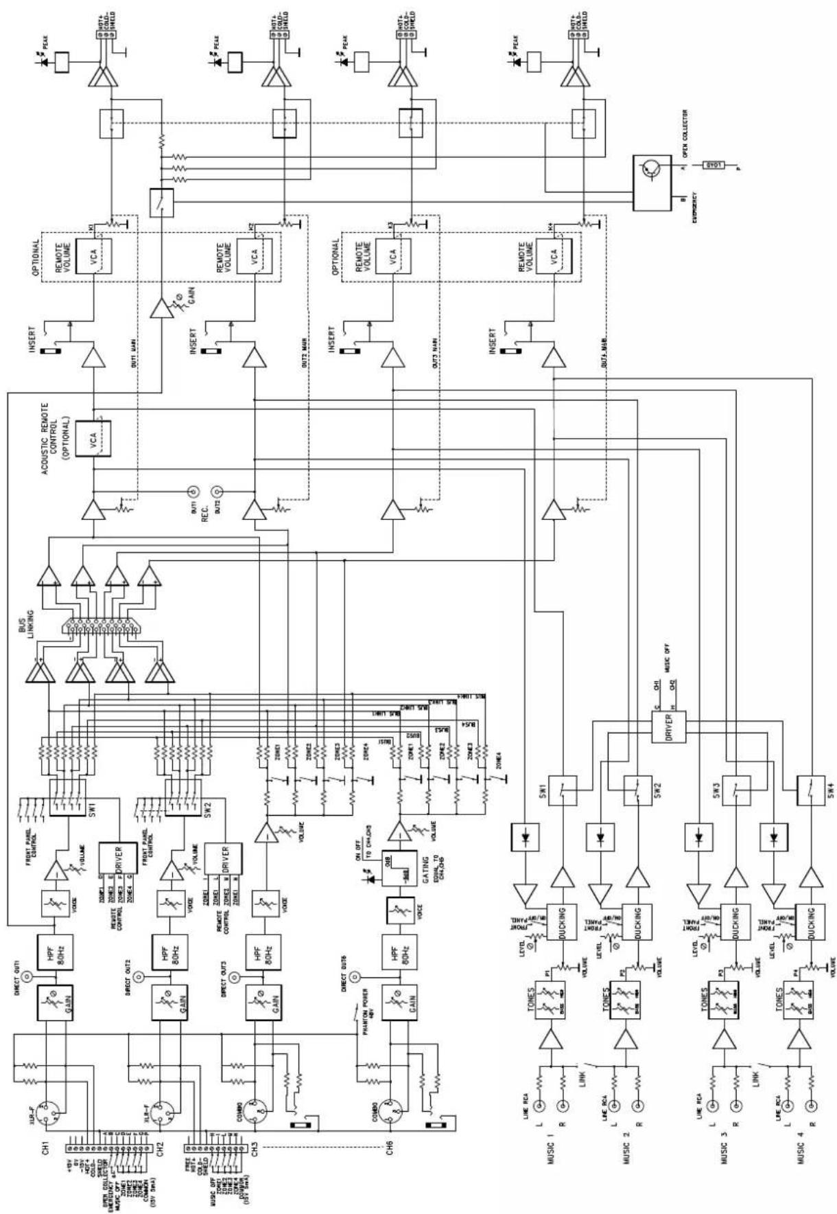
| BLOCK DIAGRAM | 15-16 |
| TECHNICAL SPECIFICATIONS | 17 |
| NOTES | 18 |
I
INTRODUZIONE
MMZ 8004S mixer has been specially designed and developed to solve in a simple way the many needs and requirements of sound distribution in complex amplification systems, such as: combination of zones, selective announcements, transmitting different music programs to different zones, remote adjustment of levels and automatic control of volume according to room noise.
The feeling of easy use is immediate, and the efforts and care FBT has taken in designing this equipment are appreciated for its wide application in public address systems, meeting today's increasingly more sophisticated needs and requirements in a simple and rational way.
The present manual describes the many applications highlighting the surprising flexibility and versatility of this system.
We suggest that you carefully read these pages, in order to get the most from the performance offered by these appliances, and also to discover fields of use other than those which determined the purchase.
I
IMPORTANTE
Before connecting and using the equipment, read the instructions in this manual carefully.
Read the notes preceded by this symbol with special attention as they provide important safety information.

I
AVVERTENZE
- Avoid installing the mixer near sources of excessive heat, exposing it to direct sunlight or leaving it unprotected in dusty surroundings.
When connecting external appliances as a sound system chain (mixer, power amplifier, electronic equipment, etc.) some noise (hum) or buzz may be heard: in general, the cause is to ascribe to earth loops. The most effective way to avoid such disturbance consists in connecting the earth of the various audio appliances to one specific point (star connection).
Do not force the control knobs or pushbuttons: they are designed to respond to light pressure and could be damage if pressed too hard.
Do not use solvents such as acetone or alcohol to clean the mixer, as they would damage its finish and the writing on its panels.
° In the event of malfunction of any part of the system, contact the nearest assistance centre, but never try to carry out repairs yourself.
The mixer is fed with an external adapter with double insulation, supplying low voltage and guaranteeing a high degree of safety for the user.
The external feeder must be positioned so that:
- it does not come into contact with sharp metal bodies that can perforate the container;
- it is distant from the input circuits and the screened cables of the signal connections;
- the feed cable is not squashed or cut.
I
AVVERTENZE


ATTENZIONE
RISCHIO DI SCOSSA ELETTRICA NON APRIRE
ATTENZIONE
PER EVITARE IL RISCHIO DI SCOSSE ELETTRICHE NON USARE UTENSILI METALLICI ALL'INTERNO
ATTENZIONE
PER PREVENIRE IL RISCHIO DI FIAMME O SCOSSE ELETTRICHE NON ESPORRE L'APPARECCHIO ALLA.PIOGGIA O ALL'UMIDITA
ATTENZIONE
RISCHIO DI SCOSSA ELETTRICA: L'APPARECCHIATURA DEVE ESSERE APERTA SOLTANTO DA PERSONALE QUALIFICATO
I
INSTALLAZIONE
TO PREVENT FIRE OR ELECTRIC SHOCK DO NOT EXPOSE THIS EQUIPMENT TO RAIN OR MOISTURE
CAUTION
RISK OF ELECTRIC SHOCK: OPEN ONLY IF QUALIFIED AS SERVICE PERSONNEL
UK
INSTALLATION
Although it is neither complicated to install nor difficult to operate your amplifier, a few minutes of your time is required to read this manual for a properly wired installation and becoming familiar with its many features and how to use them. Please take a great care in unpacking your set and do not discard the carton and other packing materials: they may be needed when moving your set and are required if it ever becomes necessary to return your set for services. Never place the unit near radiator, in front of heating vents, to direct sunlight, in excessive humid or dusty location to avoid early damage and for your years of quality use. Connect your complementary components as illustrated in the following pages.
When the unit is installed in a rack enclosure, the rack must have all the prerequisites required by the EN 60439-1 standard, in particular the rear part must be closed by means of suitable panels.
SK
° Before using the amplifier for the first time make sure that the appliance's voltage is in accordance to your mains supply. Connect the unit only to grounded mains outlets.
° The unit must only be supplied from the mains after all connections have been completed.
flowchart
graph TD
    A["Ch 1: VOLUME VOICE VOICE"] --> B["CH 2: VOLUME VOLUME"]
    B --> C["CH 3: VOLUME VOLUME"]
    C --> D["CH 4: VOLUME VOLUME VOICE VOICE"]
    D --> E["CH 5: VOLUME VOLUME VOLUME"]
    E --> F["Zone 1 MUSIC: VOLUME HIGH LOW"]
    F --> G["Zone 2 MUSIC: VOLUME HIGH LOW"]
    G --> H["Zone 3 MUSIC: VOLUME HIGH LOW"]
    H --> I["Zone 4 MUSIC: VOLUME HIGH LOW"]
    I --> J["Output: MMZ-8004 S"]

    style A fill:#f9f,stroke:#333
    style B fill:#f9f,stroke:#333
    style C fill:#f9f,stroke:#333
    style D fill:#f9f,stroke:#333
    style E fill:#f9f,stroke:#333
    style F fill:#ccf,stroke:#333
    style G fill:#ccf,stroke:#333
    style H fill:#ccf,stroke:#333
    style I fill:#ccf,stroke:#333

    subgraph Channels
        direction TB
        A --> CH1["VOLUME VOICE VOICE"]
        B --> CH2["VOLUME VOLUME"]
        C --> CH3["VOLUME VOLUME"]
        D --> CH4["VOLUME VOLUME VOICE VOICE"]
        E --> CH5["VOLUME VOLUME VOLUME VOICE"]
    end

    subgraph Outputs
        direction LR
        F --> SOURCES["SOURCES"]
        G --> SOURCESS["NECK"]
        H --> SOURCESS["NECK"]
        I --> SOURCESS["NECK"]
        J --> PEAK["PEAK"]
    end

    subgraph Outputs
        direction CS
        K["1"] --> A
        L["2"] --> M["3"] --> N["4"] --> O["5"]
    end
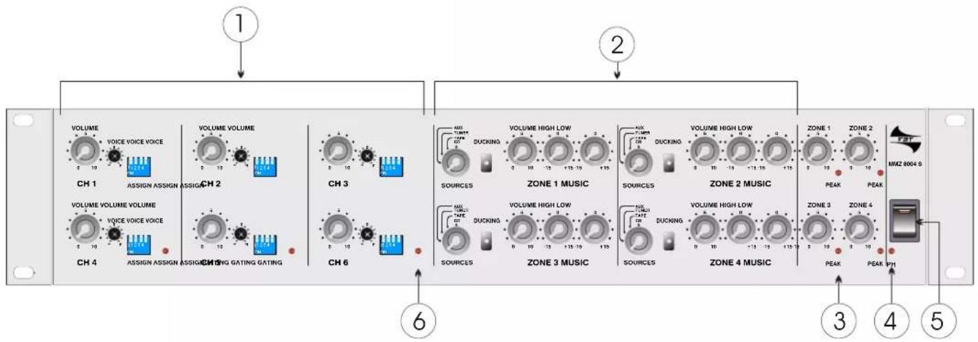
1] VOLUME - adjusts the sound volume of the channel.
VOICE - regulates the clarity of speech.
ASSIGN- manual switch for assigning the channel to the various zones.
2] ZONE MUSIC (1-2-3-4) - controls for adjusting the volume, bass and treble of the music transmitted to the various zones. CD, TAPE, TUNER, AUX selected on each output zone.
DUCKING- manual switch lowering the music according to the voice level.
3] MASTER - general volumes of the zones (1,2,3,4). PEAK- red LED, indicates that the output signal is too great, therefore it is advisable to lower it by operating the Volume Master knob.
4] PH - the LED comes on when the Phantom voltage of 48Vdc is present in pins 2 and 3 of the XLR connector of all the channel inputs; turned on by means of the switch (13) located on the back panel.
I
CONTROLS AND FUNCTIONS
FRONT PANEL
5] POWER- system on: connects the output of the external adapter to the internal circuits.
6] GATING- indicates turning on of the function enabling the voice level to be raised before the Larsen effect (annoying whistling) occurs.
See example of use on page 11
To set the Gating function, carry out the following procedure:
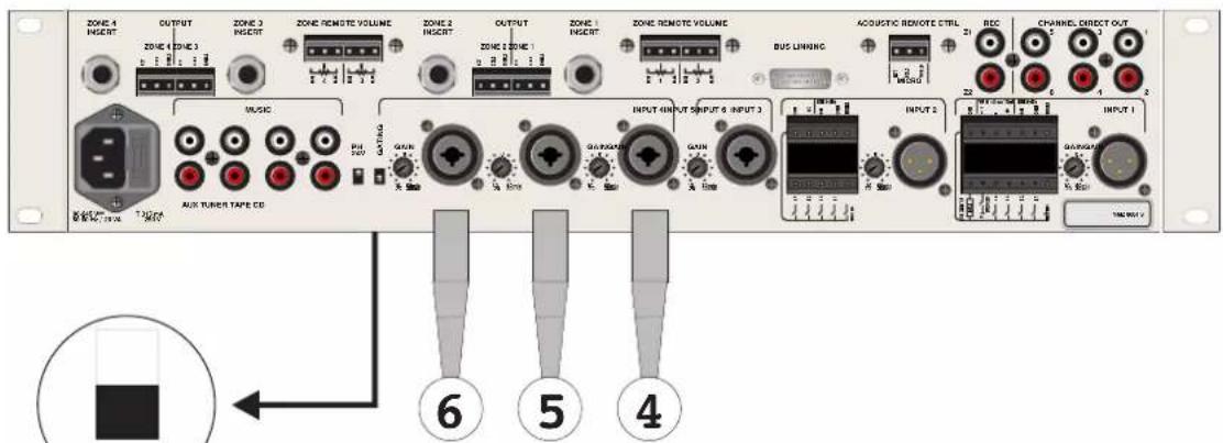
# turn off GATING
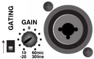
# after connecting the three microphones to inputs 4,5,6 and turning the relative Gain controls to the middle position, operate the knobs of the relative volumes, turning them to the same position until the limit of "whistling".
# the "whistling" will have disappeared; this is the maximum voice level that can be obtained without the Larsen effect, always taking into account the type of microphone, the room, the speaker/microphone distance, etc.
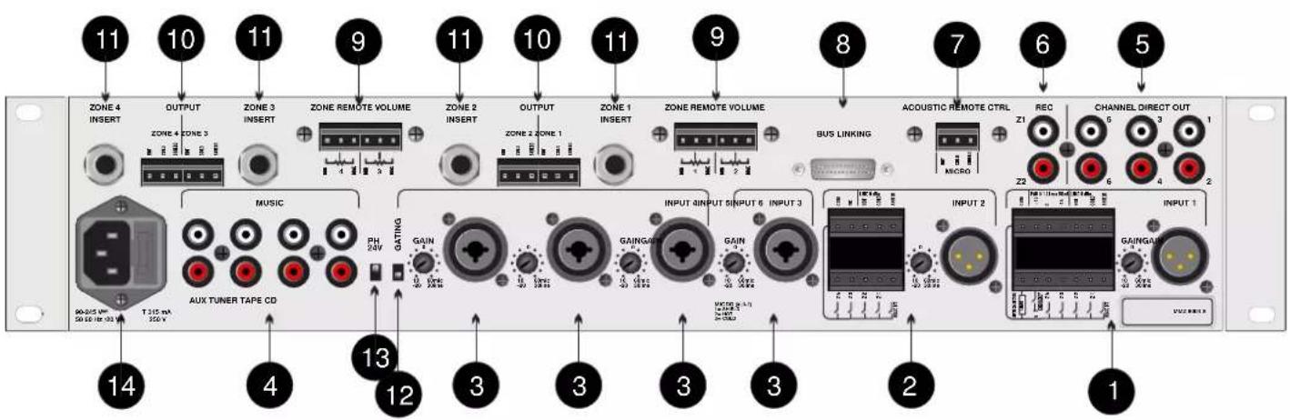
1] Connections and controls of channel 1:
-XLR_F:CH1 balanced microphone input
-GAIN: optimizes the level of sources adjusting amplification of the Mic input signal from 10dB to 60dB and Line from -20dB to 30dB
- 14 pin CONNECTOR:
I) control of paging and turning off the music source (see example on page 12)
II) open collector output (see drawing on page 12)
III) common (+15V) to be used for paging logic controls different to those used by the "FBT"
IV) power supply +/- 15V max. current 150mA
V) line input (0dBu/0.775V) of channel 1
2] Connections and controls of channel 2:
-XLR_F: CH2 balanced microphone input
-GAIN: optimizes the level of sources adjusting amplification of the Mic input signal from 10dB to 60dB and Line from -20dB to 30dB
- 10 pin CONNECTOR:
I) control of paging and turning off the music source (see example on page 12)
II) common (+15V) to be used for paging logic controls different to those used by the "FBT"
III) line input (0dBu/0.775V) of channel 2
I
CONTROLS AND FUNCTIONS
REAR PANEL
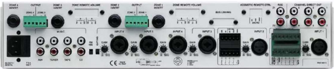
3] Input channels 3, 4, 5, 6:
- NEUTRIK Combo socket for XLR-F for connecting the (1mV) balanced microphone input and stereo JACK for the balanced line input (0.775V).
-GAIN: optimizes the level of sources adjusting amplification of the input signal
4] Inputs of music sources transmitted to specific zones.
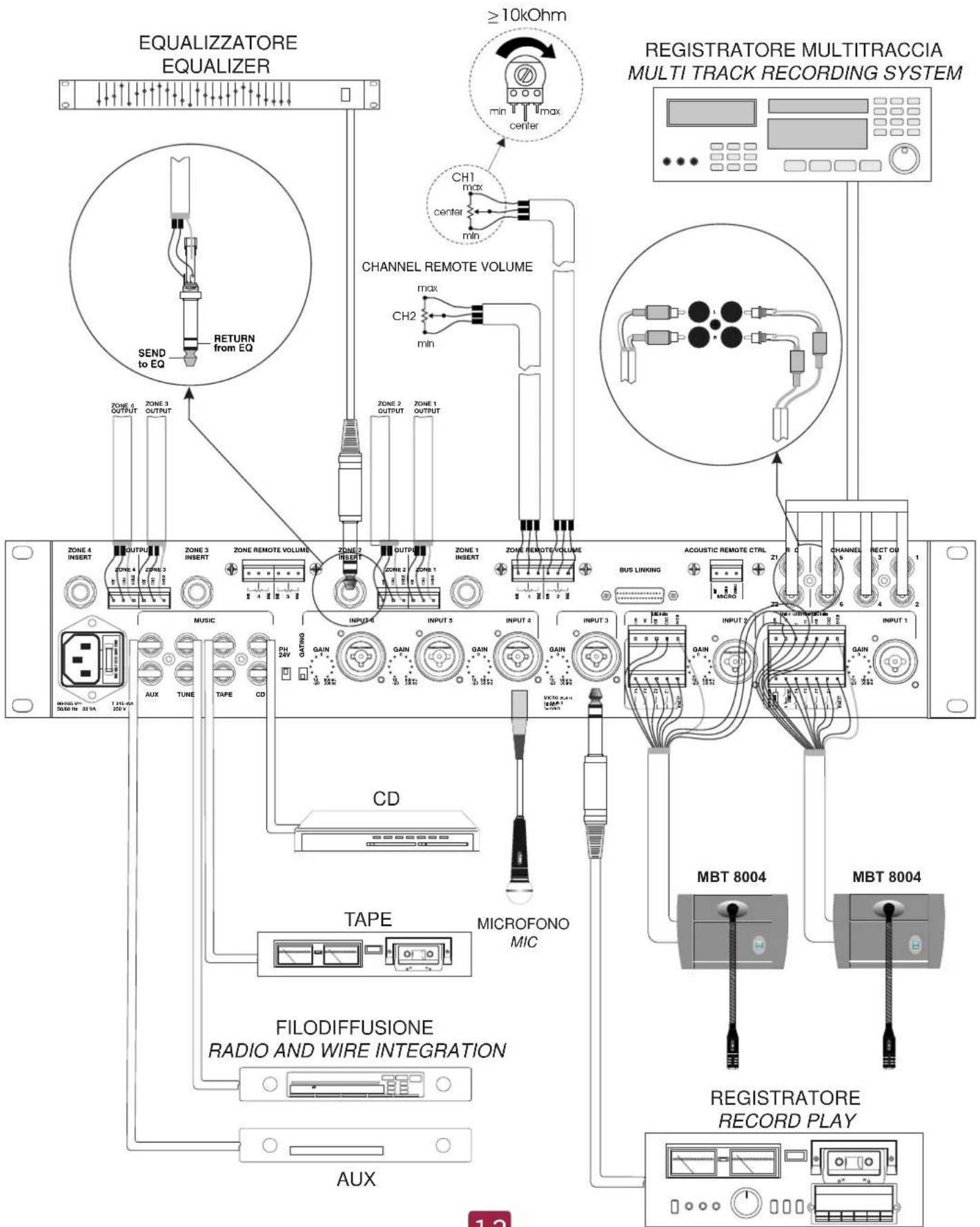
5] Direct outputs of single channels. The signal is picked up after the Gain stage (the level is 0dBm) (see examples of use on pages 12,14)
6] Outlets for recording the signals present in Zones 1 and 2 (see drawing on pages 12)
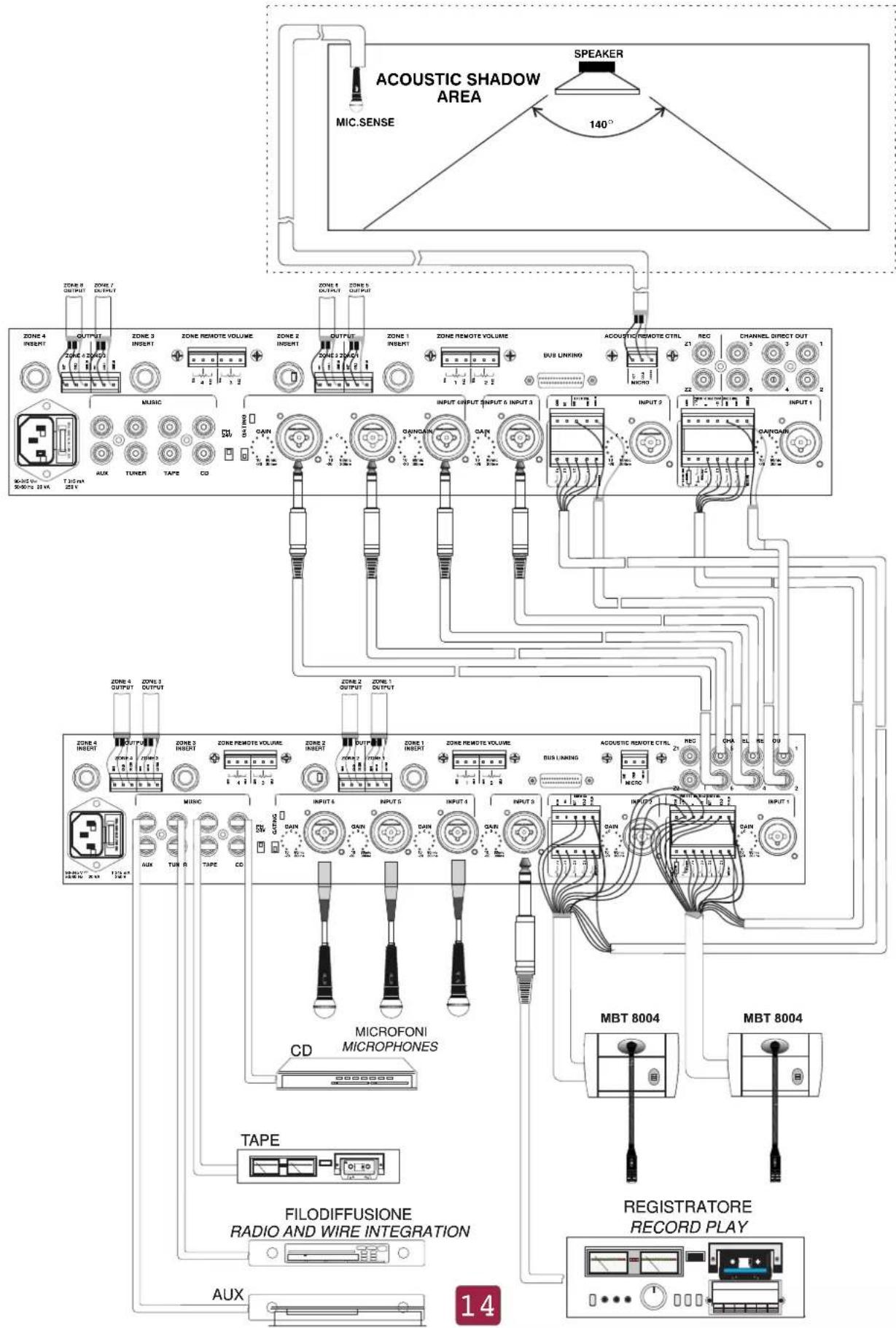
7] 3 pin connector; acoustic sensor (mic) input located in the room to detect background noise, whose value determines the voice volume
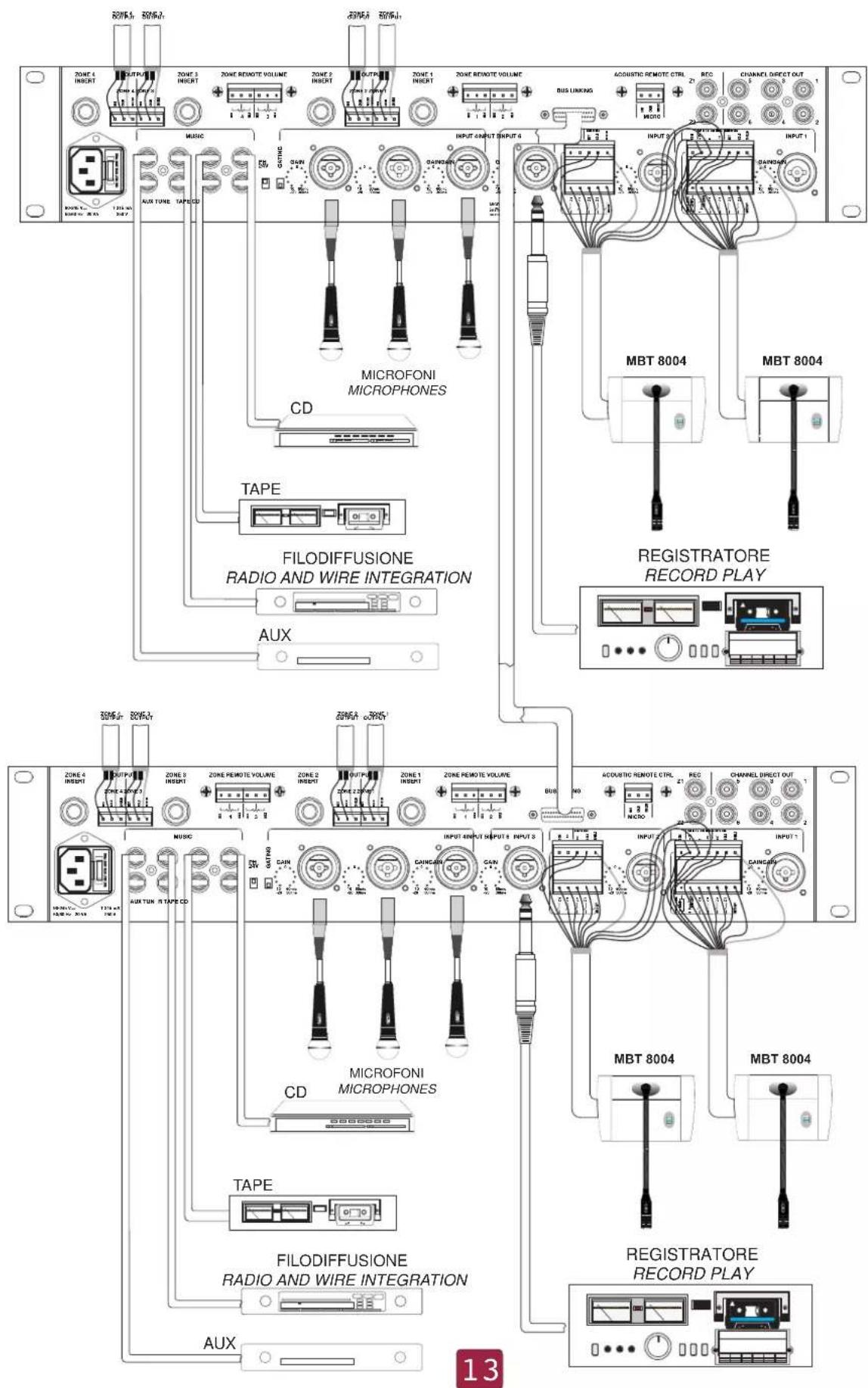
8] Connector (optional) enabling the connection of two mixers, for doubling the inputs (12) with 4 outputs. In this way the output signal of the same zone, of each mixer, is equal; the same signal can be equalized and the volume adjusted differently (see example on page 13)
9] 6 pin connector; connects the remote potentiometers regulating the volume of the two amplifiers (see example on pages 12)
10] 6 pin connector; balanced outputs of the signal of zones 1/2 or 3/4 (see example on pages 12)
11] Stereo jack for connecting an external equalizer, noise gate, limiter, etc., to the relative zone (see example on pages 12)
12] Turns on GATING in channels 4, 5, and 6. (see point 6 on page 5)
13] Switch for turning on the Phantom voltage on all pins 2 and 3 of XLR-F connectors used as micro inputs.
14] Power supply
PAGING 2 ZONE 2 ZONE PAGING
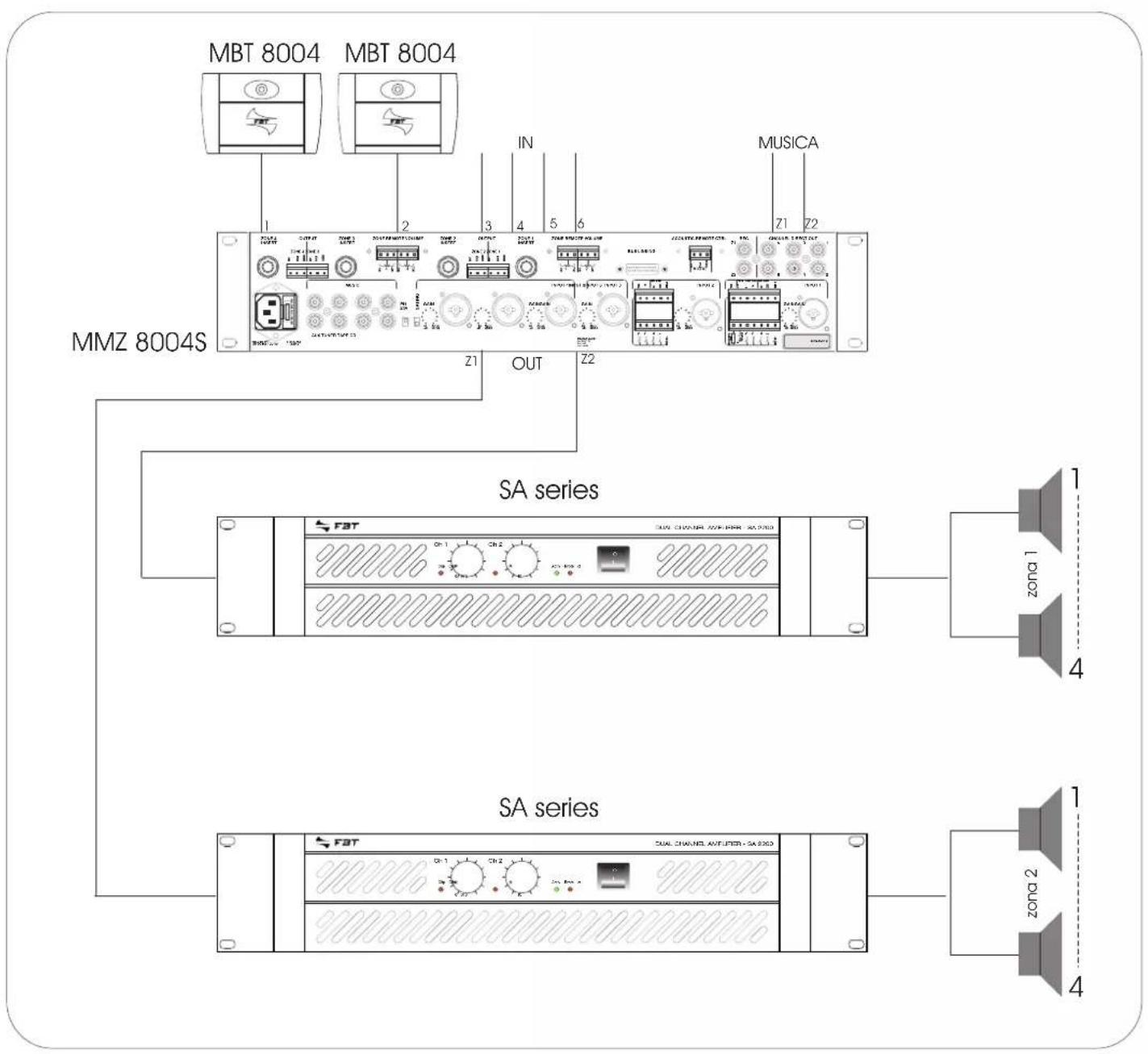
PAGING 4 ZONE 4 ZONE PAGING
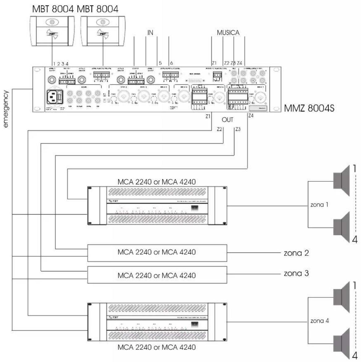
flowchart
graph TD
    A["MBT 8004 MBT 8004"] --> B["1 2 3 4"]
    A --> C["IN"]
    A --> D["MUSICA"]
    A --> E["MMZ 8004S"]
    B --> F["Emergency"]
    C --> G["Emergency"]
    D --> H["Emergency"]
    E --> I["Emergency"]
    F --> J["MCA 2240 or MCA 4240"]
    G --> K["MCA 2240 or MCA 4240"]
    H --> L["MCA 2240 or MCA 4240"]
    I --> M["MCA 2240 or MCA 4240"]
    J --> N["zona 1"]
    K --> O["zona 2"]
    L --> P["zona 3"]
    M --> Q["zona 4"]
    N --> R["zona 1"]
    O --> S["zona 2"]
    P --> T["zona 3"]
    Q --> U["zona 4"]
-PAGING 4 ZONE

CONFIGURAZIONE MMZ 8004 CONFIGURATION MMZ 8004
CONFIGURAZIONE DI 12 INGRESSI SU 4 ZONE CONFIGURATION OF 12 INPUTS IN 4 ZONES
CONFIGURAZIONE DI 6 INGRESSI SU 8 ZONE CONFIGURATION OF 6 INPUTS IN 8 ZONES
flowchart
graph TD
    A["Speaker"] -->|140°| B["MicroSENSE"]
    B --> C["ACOUSTIC SHADOW AREA"]
    C --> D["Microphone 1"]
    C --> E["Microphone 2"]
    C --> F["Microphone 3"]
    C --> G["Microphone 4"]
    C --> H["Microphone 5"]
    C --> I["Microphone 6"]
    C --> J["Microphone 7"]
    C --> K["Microphone 8"]
    C --> L["Microphone 9"]
    C --> M["Microphone 10"]
    C --> N["Microphone 11"]
    C --> O["Microphone 12"]
    C --> P["Microphone 13"]
    C --> Q["Microphone 14"]
    C --> R["Microphone 15"]
    C --> S["Microphone 16"]
    C --> T["Microphone 17"]
    C --> U["Microphone 18"]
    C --> V["Microphone 19"]
    C --> W["Microphone 20"]
    C --> X["Microphone 21"]
    C --> Y["Microphone 22"]
    C --> Z["Microphone 23"]
    C --> AA["Microphone 24"]
    C --> AB["Microphone 25"]
    C --> AC["Microphone 26"]
    C --> AD["Microphone 27"]
    C --> AE["Microphone 28"]
    C --> AF["Microphone 29"]
    C --> AG["Microphone 30"]
    C --> AH["Microphone 31"]
    C --> AI["Microphone 32"]
    C --> AJ["Microphone 33"]
    C --> AK["Microphone 34"]
    C --> AL["Microphone 35"]
    C --> AM["Microphone 36"]
    C --> AN["Microphone 37"]
    C --> AO["Microphone 38"]
    C --> AP["Microphone 39"]
    C --> AQ["Microphone 40"]
    C --> AR["Microphone 41"]
    C --> AS["Microphone 42"]
    C --> AT["Microphone 43"]
    C --> AU["Microphone 44"]
    C --> AV["Microphone 45"]
    C --> AW["Microphone 46"]
    C --> AX["Microphone 47"]
    C --> AY["Microphone 48"]
    C --> AZ["Microphone 49"]
    C --> BA["Microphone 50"]
    C --> BB["Microphone 51"]
    C --> BC["Microphone 52"]
    C --> BD["Microphone 53"]
    C --> BE["Microphone 54"]
    C --> BF["Microphone 55"]
    C --> BG["Microphone 56"]
    C --> BH["Microphone 57"]
    C --> BI["Microphone 58"]
    C --> BJ["Microphone 59"]
    C --> BK["Microphone 60"]
    C --> BL["Microphone 61"]
    C --> BM["Microphone 62"]
    C --> BN["Microphone 63"]
    C --> BO["Microphone 64"]
    C --> BP["Microphone 65"]
    C --> BQ["Microphone 66"]
    C --> BR["Microphone 67"]
    C --> BS["Microphone 68"]
    C --> BT["Microphone 69"]
    C --> BU["Microphone 70"]
    C --> BV["Microphone 71"]
    C --> BW["Microphone 72"]
    C --> BX["Microphone 73"]
    C --> BY["Microphone 74"]
    C --> BZ["Microphone 75"]
    C --> CA["Microphone 76"]
    C --> CB["Microphone 77"]
    C --> CC["Microphone 78"]
    C --> CD["Microphone 79"]
    C --> CE["Microphone 80"]
    C --> CF["Microphone 81"]
    C --> CG["Microphone 82"]
    C --> CH["Microphone 83"]
    C --> CI["Microphone 84"]
    C --> CJ["Microphone 85"]
    C --> CK["Microphone 86"]
    C --> CL["Microphone 87"]
    C --> CM["Microphone 88"]
    C --> CN["Microphone 89"]
    C --> CO["Microphone 90"]
    C --> CP["Microphone 91"]
    C --> CS["Microphone 92"]
    C --> CT["Microphone 93"]
    C --> CU["Microphone 94"]
    C --> CV["Microphone 95"]
    C --> CW["Microphone 96"]
    C --> CX["Microphone 97"]
    C --> CYB["Microphone 98"]
    C --> CZB["Microphone 99"]
flowchart
graph TD
    A["CH1"] --> B["CH2"]
    B --> C["CH3"]
    C --> D["CH4"]
    D --> E["CH5"]
    E --> F["CH6"]
    F --> G["CH7"]
    G --> H["CH8"]
    H --> I["CH9"]
    I --> J["CH10"]

    subgraph Inputs
        K["LEF-1"] --> L["LEF-2"]
        M["LEF-3"] --> N["LEF-4"]
        O["LEF-5"] --> P["LEF-6"]
        Q["LEF-7"] --> R["LEF-8"]
        S["LEF-9"] --> T["LEF-10"]
        U["LEF-11"] --> V["LEF-12"]
        W["LEF-13"] --> X["LEF-14"]
        Y["LEF-15"] --> Z["LEF-16"]
        AA["LEF-17"] --> AB["LEF-18"]
        AC["LEF-19"] --> AD["LEF-20"]
        AE["LEF-21"] --> AF["LEF-22"]
        AG["LEF-23"] --> AH["LEF-24"]
        AI["LEF-25"] --> AJ["LEF-26"]
        AK["LEF-27"] --> AL["LEF-28"]
        AM["LEF-29"] --> AN["LEF-30"]
        AO["LEF-31"] --> AP["LEF-32"]
        AQ["LEF-33"] --> AR["LEF-34"]
        AS["LEF-35"] --> AT["LEF-36"]
        AU["LEF-37"] --> AV["LEF-38"]
        AW["LEF-39"] --> AX["LEF-40"]
        AY["LEF-41"] --> AZ["LEF-42"]
        BA["LEF-43"] --> BB["LEF-44"]
        BC["LEF-45"] --> BD["LEF-46"]
        BE["LEF-47"] --> BF["LEF-48"]
        BG["LEF-49"] --> BH["LEF-50"]
        BI["LEF-51"] --> BJ["LEF-52"]
        BK["LEF-53"] --> BL["LEF-54"]
        BM["LEF-55"] --> BN["LEF-56"]
        BO["LEF-57"] --> BP["LEF-58"]
        BQ["MUSIC 1"] --> BR["LIME RD"]
        BS["MUSIC 2"] --> BT["LIME RD"]
        BU["MUSIC 3"] --> BV["LIME RD"]
        BW["MUSIC 4"] --> BX["LIME RD"]
    end

    subgraph Outputs
        BY["VCA"] -->|INSERT| Z["VCA"]
        Z -->|OPTIONAL| AA
        AA -->|OPTIONAL| AB
        AB -->|OPTIONAL| AC
        AC -->|OPTIONAL| AD
        AD -->|OPTIONAL| AE
        AE -->|OPTIONAL| AF
        AF -->|OPTIONAL| AG
        AG -->|OPTIONAL| AH
        AH -->|OPTIONAL| AI
        AI -->|OPTIONAL| AJ
        AJ -->|OPTIONAL| AK
        AK -->|OPTIONAL| AL
        AL -->|OPTIONAL| AM
        AM -->|OPTIONAL| AN
        AN -->|OPTIONAL| AO
        AO -->|OPTIONAL| AP
        AP -->|OPTIONAL| AQ
        AQ -->|OPTIONAL| AR
        AR -->|OPTIONAL| AS
        AS -->|OPTIONAL| AT
        AT -->|OPTIONAL| AU
        AU -->|OPTIONAL| AV
        AV -->|OPTIONAL| AW
        AW -->|OPTIONAL| AX
        AX -->|OPTIONAL| AY
        AY -->|OPTIONAL| AZ
        AZ -->|OPTIONAL| BA
    end

    %% Inputs & Outputs
    %% Outputs
    %% Outputs
    %% Outputs
    %% Outputs
    %% Outputs
    %% Outputs
    %% Outputs
    %% Outputs
    %% Outputs
    %% Outputs
    %% Outputs
    %% Outputs
    %% Outputs
    %% Outputs
    %% Outputs
    %% Outputs
    %% Outputs
    %% Outputs
    %% Outputs
    %% Outputs
    %% Outputs
    %% Outputs
    %% Outputs
    %% Outputs
    %% Outputs
    %RH["%"] --> HFF["HFP 80Hz"]
    %RH["%"] --> GAIN["GAIN"]
    %RH["%"] --> OUTOUTOUTOUTOUTOUTOUTOUTOUTOUTOUTOUTOUTOUTOUTOUTOUTOUTOUTOUTOUTOUTOUTOUTOUTOUTOUTOUTOUTOUTOUTOUTOUTOUTOUTOUTOUTOUTOUTOUTOUTOUTOUTOUTOUTOUTOUTOUTOUTOUTOUTOUTOUTOUTOUTOUTOUTOUTOUTOUTOUTOUTOUTOUTOUTOUTOUTOUTOUTOUTOUTOUTOUTOUTOUTOUTOUTOUTOUTOUTOUTOUTOUTOUTOUTOUTOUTOUTOUTOUTOUTOUTOUTOUTOUTOUTOUTOUTOUTOUTOUT OUTOUT OUT OUT OUT OUT OUT OUT OUT OUT OUT OUT OUT OUT OUT OUT OUT OUT OUT OUT OUT OUT OUT OUT OUT OUT OUT OUT OUT OUT OUT OUT OUT OUT OUT OUT OUT OUT OUT OUT OUT OUT OUT OUT OUT OUT OUT OUT OUT OUT OUT OUT OUT OUT OUT OUT OUT OUT OUT OUT OUT OUT OUT OUT OUT OUT OUT OUT OUT OUT OUT OUT OUT OUT OUT OUT OUT OUT OUT OUT OUT OUT OUT OUT OUT OUT OUT OUT OUT OUT OUT OUT OUT OUT OUT OUT OUT OUT OUT OUT OUT OUT UTRGT1A1A1B1C1D1E1E1E1E1E1E1E1E1E1E1E1E1E1E1E1E1E1E1E1E1E1E1E1E1E1E1E1E1E1E1E1E1E1E1E1E1E1E1E1E1E1E1E1E1E1E1E1E1E1E1A2B2C3D4D5D6D7D8D9D10D11D12D13D14D15D16D17D18D19D20D21D22D23D24D25D26D27D28D29D30D31D32D33D34D35D36D37D38D39D40D41D42D43D44D45D46D47D48D49D50D51D52D53D54D55D56D57D58D59D60D61D62D63D64D65D66D67D68D69D70D71D72D73D74D75D76D77D78D79D80D81D82D83D84D85D86D87D88D89D90D91D92D93D94D95D96D97D98D99T00T01T02T03T04T05T06T07T08T09T10T11T12T13T14T15T16T17T18T19T20T21T22T23T24T25T26T27T28T29T30T31T32T33T34T35T36T37T38T39T40T41T42T43T44T45T46T47T48T49T50T51T52T53T54T55T56T57T58T59T60T61T62T63T64T65T66T67T68T69T70T71T72T73T74T75T76T77T78T79T80T81T82T83T84T85T86T87T88T89T90T91T92T93T94T95T96T97T98T99T00T01T02T03 T04 T05 T06 T07 T08 T09 T10 T11 T12 T13 T14 T15 T16 T17 T18 T19 T20 T21 T22 T23 T24 T25 T26 T27 T28 T29 T30 T31 T32 T33 T34 T35 T36 T37 T38 T39 T40 T41 T42 T43 T44 T45 T46 T47 T48 T49 T50 T51 T52 T53 T54 T55 T56 T57 T58 T59 T60 T61 T62 T63 T64 T65 T66 T67 T68 T69 T70 T71 T72 T73 T74 T75 T76 T77 T78 T79 T80 T81 T82 T83 T84 T85 T86 T87 T88 T89 T90 T91 T92 T93 T94 T95 T96 T97 T98 T99 T00
    %% Outputs
    %% Outputs
    %% Outputs
    %% Outputs
    %% Outputs
    %% Outputs
    %% Outputs
    %% Outputs
    %% Outputs
    %% Outputs
    %% Outputs
    %% Outputs
    %% Outputs
    %% Outputs
    %% Outputs
    %% Outputs
    %% Outputs
    %% Outputs
    %% Outputs
    %% Outputs
    %% Outputs
    %% Outputs
    %% Outputs
    %% Outputs
    %% OUTPUTS
    %% OUTPUTS
    %% OUTPUTS
    %% OUTPUTS
    %% OUTPUTS
    %% OUTPUTS
    %% OUTPUTS
    %% OUTPUTS
    %% OUTPUTS
    %% OUTPUTS
    %% OUTPUTS
    %% OUTPUTS
    %% OUTPUTS
    %% OUTPUTS
    %% OUTPUTS
    %% OUTPUTS
    %% OUTPUTS
    %% OUTPUTS
    %% OUTPUTS
    %% OUTPUTS
    %% OUTPUT SUTS
    %% OUTPUT SUTS
    %% OUTPUT SUTS
    %% OUTPUT SUTS
    %% OUTPUT SUTS
    %% OUTPUT SUTS
    %% OUTPUT SUTS
    %% OUTPUT SUTS
    %% OUTPUT SUTS
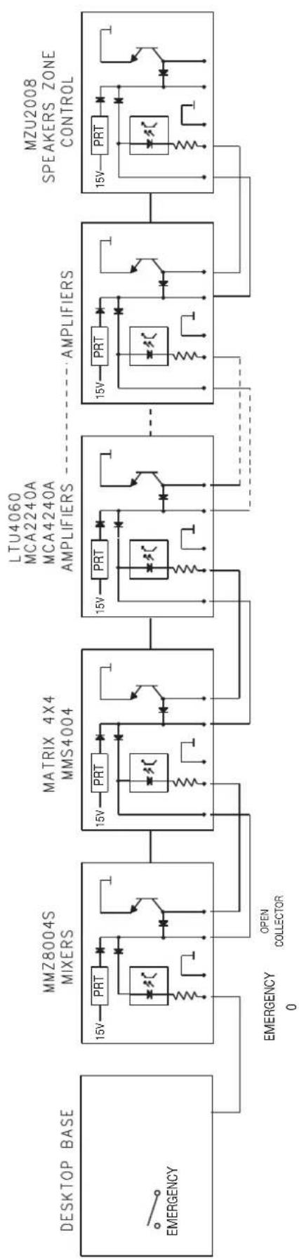
EMERGENZA COMANDATA DALLA BASE DA TAVOLO EMERGENCY CONTROLLED BY TABLE BASE
flowchart
graph LR
    A["DESKTOP BASE"] --> B["MMZ8004S MIXERS"]
    B --> C["MATRIX 4X4 MMS4004"]
    C --> D["LTU4060 MCA2240A MCA4240A AMPLIFIERS"]
    D --> E["AMPLIFIERS"]
    E --> F["MZU2008 SPEAKERS ZONE CONTROL"]
    B --> G["15V PRT"]
    C --> H["15V PRT"]
    D --> I["15V PRT"]
    E --> J["15V PRT"]
    F --> K["15V PRT"]
    G --> L["EMERGENCY 0"]
    H --> M["OPEN COLLECTOR"]
    I --> N["EMERGENCY 0"]
    J --> O["EMERGENCY 0"]
EMERGENZA COMANDATA DA UN APPARECCHIO QUALSIASI DELLA CATENA
EMERGENCY CONTROLLED BY ANY APPLIANCE OF THE CHAIN
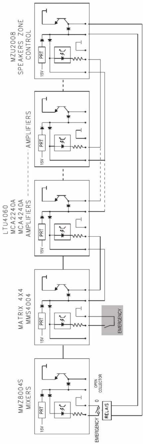
flowchart
graph LR
    A["RELAS"] --> B["15V PRT"]
    B --> C["0"]
    C --> D["OPEN COLLECTOR"]
    D --> E["EMERGENCY"]
    E --> F["15V PRT"]
    F --> G["15V PRT"]
    G --> H["LTU4060 MCA2240A MCA4240A AMPLIFIERS"]
    H --> I["AMPLIFIERS"]
    I --> J["15V PRT"]
    J --> K["15V PRT"]
    K --> L["MZU2008 SPEAKERS ZONE CONTROL"]
    L --> M["15V PRT"]
    M --> N["15V PRT"]
    N --> O["15V PRT"]
    O --> P["15V PRT"]
    P --> Q["15V PRT"]
    Q --> R["15V PRT"]
    R --> S["15V PRT"]
    S --> T["15V PRT"]
    T --> U["15V PRT"]
    U --> V["15V PRT"]
    V --> W["15V PRT"]
    W --> X["15V PRT"]
    X --> Y["15V PRT"]
    Y --> Z["15V PRT"]
    Z --> AA["15V PRT"]
    AA --> AB["15V PRT"]
    AB --> AC["15V PRT"]
    AC --> AD["15V PRT"]
    AD --> AE["15V PRT"]
    AE --> AF["15V PRT"]
    AF --> AG["15V PRT"]
    AG --> AH["15V PRT"]
    AH --> AI["15V PRT"]
    AI --> AJ["15V PRT"]
    AJ --> AK["15V PRT"]
    AK --> AL["15V PRT"]
    AL --> AM["15V PRT"]
    AM --> AN["15V PRT"]
    AN --> AO["15V PRT"]
    AO --> AP["15V PRT"]
    AP --> AQ["15V PRT"]
    AQ --> AR["15V PRT"]
    AR --> AS["15V PRT"]
    AS --> AT["15V PRT"]
    AT --> AU["15V PRT"]
    AU --> AV["15V PRT"]
    AV --> AW["15V PRT"]
    AW --> AX["15V PRT"]
    AX --> AY["15V PRT"]
| CARATTERISTICHE CHARACTERISTICS | 2 unità rack colore grigio RAL 7035two rack units - RAL 7035 light gray finished |
| MICROFONO / LINEA GUADAGNO MAX.MICROPHONE / LINE MAX. GAIN | 6 ingressi micro/linea 75dB-2kOhm6 input mic/line 75dB-2kOhm |
| INGRESSO 1 / 2INPUT 1 / 2 | possibilità di selezione uscita 1, 2, 3, 4, da base microfonica remota connection of desktop base with selection of channel 1, 2, 3, 4 |
| LINEA / GUADAGNO MAXLINE / MAX. GAIN | 4 ingressi stereo pin jack RCA / 40dB / 33kOhm4 stereo pin jack RCA inputs / 40dB / 33kOhm |
| RISPOSTA IN FREQUENZA @0 / -1dB FREQUENCY RESPONSE @0 / -1dB | 20Hz - 80kHz |
| RAPPORTO SEGNALE/RUMORE @20dB SIGNAL TO NOISE RATIO @20dB | 110dB |
| CONTROLLI DI LIVELLO LEVEL CONTROLS | n.10 controlli di volume, n.6 controlli gain, n.4 mastern.10 volume control, n.6 gain control, n.4 master |
| FILTRO PASSA ALTO LOW CUT FILTER | canali 1:6 micro/linea @80Hz-12dB/oct.channel 1.6 mic/line @80Hz-12dB/oct. |
| CONTROLLO VOCE VOICE CONTROL | n. 6 trimmer per regolazione presenza voce su ingressi micro n.6 speech control on mic input |
| CONTROLLI TONO TONE CONTROLS | n. 2 controlli toni bassi e alti separati solo su ingresso musica n.2 bass and high control on separate pad |
| ALIMENTAZIONE PHANTOM PHANTOM POWER SUPPLY | 48Vdc solo su ingressi micro48Vdc on microphone inputs |
| INGRESSI 1, 2, 3, 4INPUTS 1, 2, 3, 4 | selettori che permettono di indirizzare ogni ingresso su uscite 1,2,3,4, selector switches allow you to bus input signals to output 1,2,3,4, |
| INGRESSI MUSIC IMUSIC INPUTS | 4 ingressi stereo su doppi RCA per CD, Tape, Tuner e Aux selezionabili su ogni zona di uscita 4 stereo inputs on double RCA for CD, Tape, Tuner and Aux selected on each output zone |
| USCITE dB / IMPEDENZA OUTPUT dB / IMPEDANCE | 28dBu/600 Ohm bilanciate a morsettiera28dBu/600 Ohm balanced on terminal strip |
| USCITE AUSILIARIE AUXILIARY OUTPUTS | uscite dirette ch.1-6 + presa registrazione e uscita 1,2,3,4 0dBu/600Ohmdirect output ch.1-6 + rec. connectors bus 1,2,3,4 0dBu/600Ohm |
| PRIORITÀ SU MUSICA PRIORITY ON MUSIC | predisposizione con selettori su pannello frontale (ducking)mode function by selectors in front panel (ducking) |
| CONTROLLI REMOTI REMOTE CONTROLS | volume remoto uscite 1,2,3,4 / controllo automatico del livello su uscita 1 remote volume control on out 1,2,3,4 / automatic level controlon ch1 |
| CONTROLLO EMERGENZA EMERGENCY CONTROL | ingresso con fotoaccoppiatore, uscita open collector photo coupler input, open collector output |
| INSERT BUS 1 e 2 INSERT BUS 1 e 2 | presa jack 6,3mm per collegare apparecchiature ausiliariejack 6,3 mm socket |
| INDICAZIONI LUMINOSE LED INDICATIONS | peak sulle uscite 1,2,3,4 / phantom on peak indication for output 1,2,3,4 / phantom on |
| ALIMENTAZIONE Vac Vac POWER SUPPLY | 90 / 245 con alimentatore interno90 / 245 by internal power supply |
| ACCESSORI OPZIONALI OPTIONAL ACCESSORIES | scheda per controllo automatico del livello in funzione del rumore di fondo scheda per volume remoto per la coppia di uscite1/2 o 3/4 (mod. MMZ-VRC)optional card for remote volume control on outputs 1/2 and 3/4 automatic level control depending on environment noise on ch1 |

AVVERTENZE PER IL CORRETTO SMALTIMENTO DEL PRODOTTO AI SENSI DELLA DIRETTIVA EUROPEA 2002/96/EC
IMPORTANT INFORMATION FOR CORRECT DISPOSAL OF THE PRODUCT IN ACCORDANCE WITH EC DIRECTIVE 2002/96/EC
This product must not be disposed of as urban waste at the end of its working life. It must be taken to a special waste collection centre licensed by the local authorities or to a dealer providing this service. Separate disposal of electric and/or electronic equipment (WEEE) will avoid possible negative consequences for the environment and for health resulting from inappropriate disposal, and will enable the constituent materials to be recovered, with significant savings in energy and resources. As a reminder of the need to dispose of this equipment separately, the product is marked with a crossedout wheeled dustbin.

CODE: 12572
All information included in this operating manual have been scrupulously controlled; however FBT is not responsible for eventual mistakes. FBT Elettronica S.p.A. has the right to amend products and specifications without notice.
- I
- INDICE
- UK
- INDEX
- INTRODUZIONE
- IMPORTANTE
- AVVERTENZE
- ATTENZIONE
- INSTALLAZIONE
- INSTALLATION
- SK
- CONTROLS AND FUNCTIONS
- FRONT PANEL
- REAR PANEL
- CONFIGURAZIONE MMZ 8004 CONFIGURATION MMZ 8004
- CONFIGURAZIONE DI 12 INGRESSI SU 4 ZONE CONFIGURATION OF 12 INPUTS IN 4 ZONES
- CONFIGURAZIONE DI 6 INGRESSI SU 8 ZONE CONFIGURATION OF 6 INPUTS IN 8 ZONES
- CODE: 12572
Brand : FBT
Model : MMZ 8004S
Category : Blender