
140X - Professional audio equipment DBX - Free user manual and instructions
Find the device manual for free 140X DBX in PDF.


| Product Type | Audio Compressor/Limiter |
| Model | 140X |
| Brand | DBX |
| Form Factor | 1U Rackmount |
| Inputs | 2 x XLR (Analog), 2 x TRS (Analog) |
| Outputs | 2 x XLR (Analog), 2 x TRS (Analog) |
| Frequency Response | 20 Hz - 20 kHz |
| Dynamic Range | > 110 dB |
| Compression Ratio | 1:1 to ∞:1 |
| Threshold Range | -40 dBu to +20 dBu |
| Attack Time | 0.1 ms to 200 ms |
| Release Time | 0.05 s to 2 s |
| Makeup Gain | -20 dB to +20 dB |
| Power Supply | 100-240 V AC, 50/60 Hz |
| Power Consumption | 25 W |
| Dimensions (W x D x H) | 483 x 200 x 44 mm |
| Weight | 2.7 kg |
| Display | LED metering (gain reduction and output) |
| Controls | Threshold, Ratio, Attack, Release, Gain, Bypass |
| Presets | Factory presets and user programmable |
| Construction | Steel chassis, aluminum front panel |
| Cooling | Passive (fanless) |
| Operating Temperature | 0°C to 40°C |
| Included Accessories | Power cable, user manual |
Frequently Asked Questions - 140X DBX
User questions about 140X DBX
0 question about this device. Answer the ones you know or ask your own.
Ask a new question about this device
Download the instructions for your Professional audio equipment in PDF format for free! Find your manual 140X - DBX and take your electronic device back in hand. On this page are published all the documents necessary for the use of your device. 140X by DBX.
USER MANUAL 140X DBX
Type II Noise Reduction
dbx Professional Products
Introduction
Congratulations on purchasing the dbx 140X Type II Noise Reduction System. This owner's manual provides you with instructions for connecting your 140X to your system and basic operating information to help you get the most from your 140X.
The dbx Model 140X Type II System is an encode-decode "Compression/Expansion" or companding system based on patented True RMS™ detector circuitry. It is designed for applications where bandwidth is limited, where it yields:
• Doubling of effective dynamic range
• A greater than 40dB improvement in S/N with typical media
The 140X may be used in home-studio and professional audio production applications. When used with a high-quality tape machine, its performance exceeds that of 16-bit digital. Use it with:
• Reel-to-reel tape decks operating at 7.5 IPS or slower
• Cassette decks
• PCM Digital systems (DAT, F1, etc.)
• Digital samplers (8- to 16-bit)
In broadcast industry applications use the 140X with:
- Cart machines
- Videotape recorders
• Studio Transmission Links (STLs) - Telephone lines
• "Captive" in-house audio production
The versatile 140X features:
- Two independent channels of Type II encoding
- Two independent channels of Type II decoding
• Hardware bypass on all inputs and outputs - Adjustable -24 to +10dBu nominal operating level
Input:
• Electronically balanced inputs
• Balanced or single-ended operation
• Gain trim for signal from tape deck
Output:
• Electronically balanced outputs
• Balanced or single-ended operation
• Gain trim for signal to tape deck
The 140X is fully compatible with previous dbx Type II professional products (Models 140, 140A, 142, 148, 941/942, 941A/942A and 408). It is also compatible with the "dbx consumer" NR found in many cassette recorders and home-recording tape machines. The 140X includes hardware necessary for mounting in 19" rack cabinets.
Front Panel

Figure 1: Front Panel
Power LED: Illuminates when the 140X is receiving power.
Channel A RECORD button: Press in to engage the dbx encoder.
The OUT position is a hardwire bypass switch. The inputs are connected directly to the outputs. The 140X will pass signal in this position even if it is not receiving AC power.
Channel A PLAY button: Press in to engage the dbx decoder.
The OUT position is a hardwire bypass switch. The inputs are connected directly to the outputs. The 140X will pass signal in this position even if it is not receiving AC power.
Channel A RECORD trimpot: This adjusts the gain through the encoder circuit for level matching purposes.
Channel A PLAY trimpot: This adjusts the gain through the decoder circuit for level matching purposes.
Channel B functions are identical.
Rear Panel

Figure 2: Rear Panel
From Console A and B — Encoder inputs: Connect these to your line-level audio source. Typically, this is a mixer or recording console output bus.
To Tape Rec A and B — Encoder outputs: Connect these to the line inputs on your tape deck. In other applications, these send the encoded signal to the transmission line or other audio channel. Connect these to a line amplifier, distribution amplifier, etc.
From Tape Rec A and B — Decoder inputs: Connect these to the outputs on your tape deck. In other applications, these receive an encoded signal from the transmission line or other audio channel output.
To Console A and B — Decoder outputs: Connect these to the tape playback (tape monitor) inputs on your mixer or recording console. In other applications, these send the decoded signal(s) to the input(s) of the transmitter, mixer, or similar output device.
AC Voltage Switch: Set for either 120V or 240V operation before installing the 140X.
AC Cord: Plug into mains power. Note that the 140X does not have a power switch. It is recommended that the 140X be "on" at all times. Power consumption is low.

Connecting Your 140X to Your System
System Connections
flowchart
graph LR
    A["To tape or transmission line"] --> B["Monitor Levels Here"]
    B --> C["140X Channel A"]
    C --> D["'From Console' (encode)"]
    D --> E["140X Channel A"]
    E --> F["'From Tape Rec' (decode)"]
    F --> G["Monitor Levels Here"]
    G --> H["140x is operated as part of tape deck or transmission line"]
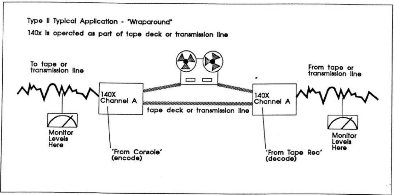
Figure 3: System Connections
Normally, the 140X will be wired directly to the inputs and outputs of a tape deck or video recorder. The encode-decode electronics "wrap around" the recording device. The 140X is considered part of the recorder or line amplifier and the trims are set for precise level matching.
There are two basic operating rules to remember:
1) Once the level of the tape deck or transmission line has been set, monitor and vary levels only before the encoder or after the decoder. Small variations won't cause Type II to misbehave, but this is a good habit to learn.
2) Never introduce any change into an encoded signal with a mixer, tone control, equalizer, or by forcing magnetic tape into saturation. Follow encode with decode, then mix and EQ, and then re-encode.
Multi-Channel Connections
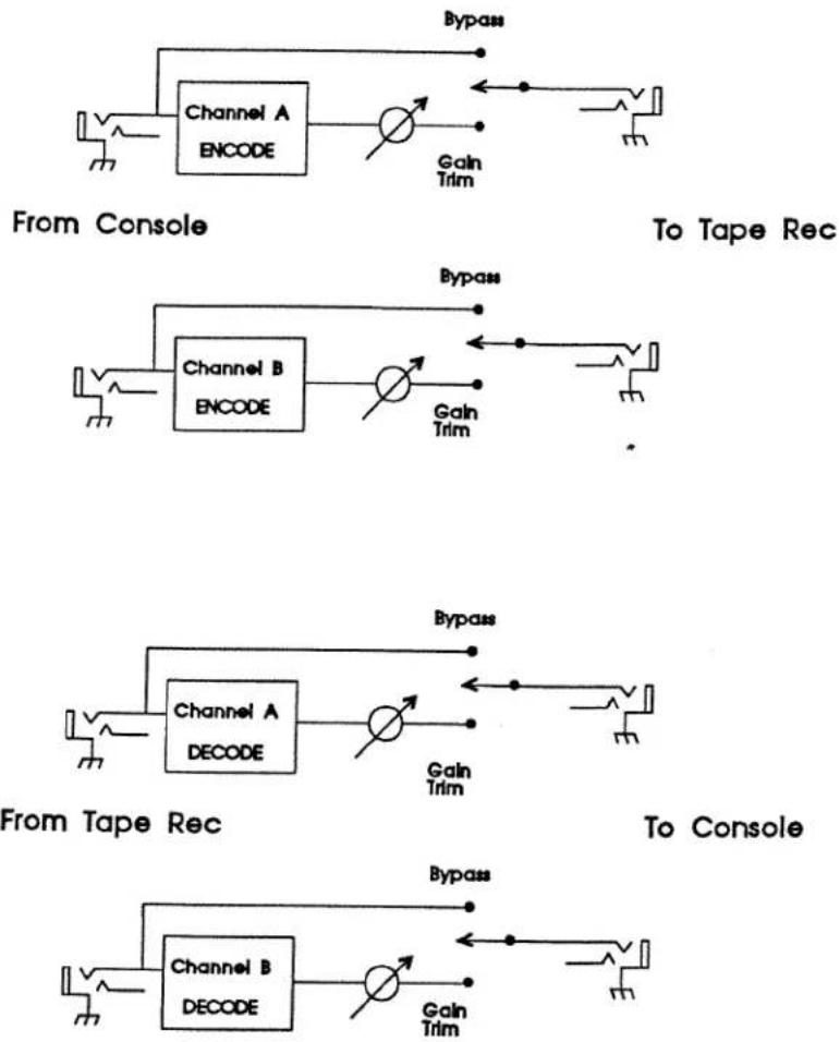
Figure 4: Multi-channel Connections
If required, the 140X can be wired to a patchbay and allowed to "float" so it can be connected to whichever device is in use at the time. The following precautions must be taken:
If the entire studio is wired for balanced operation, a TRS jack may be used in the patchbay for all 140X inputs and outputs. If the studio is wired for a mix of balanced and single-ended operation, use three-conductor balanced phone plugs for the inputs to the 140X. For the outputs from the 140X, it is best to use either (1) a three-conductor phone plug (balanced) or (2) a three-conductor phone plug with the ring disconnected (single-ended). See "Output Connections," for a full discussion.
The simplified block diagram in Figure 6 shows the two independent channels of encoding and two separate channels of decoding.
If required, Channel A can simultaneously encode a signal for Device 1 and decode a signal from Device 2, while Channel B is in Bypass for both recording and playback.
Basic Operation
Tape Recording: Adjusting Input and Output Levels
While dbx Type II is a “friendly and forgiving” system, dbx Noise Reduction is part of a total system including the tape deck’s electronics, heads, bias, EQ, and output electronics. The fewer anomalies that occur within the recorder, the better.
Before encoding Type II audio or video tapes, make sure that the recording heads are clean, demagnetized, and aligned properly. Where appropriate, make certain that the tape deck bias and EQ are properly set. Re-bias and align when changing tape formulations and speed, just as you would for optimum performance without noise reduction.
Level Adjustments
The trimpots for Record and Play levels are accessible from the front panel. Use these to keep levels matched. These settings are not critical to proper performance of the 140X processor. They are provided so the 140X matches as many different levels as possible. Trimpot range is from -24dBu to +10dBu.
Record Adjust
Don't expect the console meters and the tape recorder meters to match at frequencies above 1kHz because of the encoder's preemphasis. If you use 400Hz or some other mid-band tone, you may continue to use that, but be sure to use the same tone consistently.
1) Put the 140X in Bypass, and send a 1kHz tone from the console or audio source at your chosen 0VU.
2) Set the tape deck's meter(s) to the nominal calibration point — 0VU in this case.
3) Switch the 140X IN, and turn the RECORD Level Adjust trimpot on each channel as necessary to bring the deck's meter reading to 0VU again.
Playback Adjust
1) Put the 140X in Bypass. Using an alignment tape, send a 1kHz tone from the tape deck at 0VU.
2) Check the console meter(s) and set them at a nominal 0VU.
3) Switch the 140X IN, and turn the PLAY Level Adjust trimpot on each channel as necessary to bring the meter reading to OVU again.
Compensating for an Encoded Signal
The hotter you record (or transmit) a dbx-encoded signal, the better the overall dynamic range and signal-to-noise will be. This holds true until you hit tape saturation, at which point the playback quality will deteriorate.
With Type II NR, the chance of tape saturation is reduced even more than with Type I due to additional high-frequency preemphasis applied in the encoder. On a professional tape
machine running at 7.5, 15, or 30 IPS you will be able to record well above the traditional levels.
After a signal has been encoded, peaks are 50% lower. You are safe recording at least 50% hotter. If you have peak-reading meters on your deck, set the record levels on the machine so that the signal never exceeds the tape's headroom and you'll be fine.
With VU or averaging meters, the best way to find optimum recording levels is to experiment. When recording too hot you will begin to notice the effects of tape saturation on playback. When you find a nominal operating level which sounds good, calibrate your equipment and then ignore the meters on the tape machine(s).
Tape Mastering and Alignment Tones
Alignment tones on tape should not be encoded. The typical 100Hz - 1kHz - 10kHz tone on head or tail should be recorded without Type II processing. Some engineers also provide an encoded 1kHz tone, with the program material following. Remember that professional recording studios have standardized on Type I NR. For in-house use, this is not a concern. If a tape is going to an outside facility, it should be clearly marked "dbx Type II."
Other Applications: Adjusting Input and Output Levels
The procedure is the same as with a tape recorder. Since the signal is compressed 2:1, you may transmit at a hotter level (but do not exceed the headroom of the transmission line). Once levels are set, meter the signal before and after the 140X.
Type II and Digital Recording
dbx Type II works with 16-bit digital recorders (e.g., DAT machines). The encoding process increases the machine's dynamic range by at least 20dB. Since the audio is another 20dB higher than the noise floor, non-linearities associated with very quiet signals are eliminated. At the same time, the dbx compression helps avoid digital clipping, making for a fail-safe field recording system.
The same is true for sampling synthesizers. Any 12-, 14-, or even 8-bit sampler gives better sound with Type II NR as a permanent add-on at input and output (provided the sampler does not have some sort of commander built in).
Specific Applications
Radio Broadcast
The 140X is designed for in-house production where cart machines are used, or tape decks typically run at 7.5 IPS or slower. The 140X is compatible with existing Type II processors (Models 140, 140A, 142, 148, 941/942, 941A/942A and 408).
The 140X may be used to upgrade the performance of telephone lines (input and output matching transformers are recommended). A pair of 140Xs may be inserted into STLs to improve Signal to noise Ratio and dynamic range.
Television Studio
The 140X will also add high fidelity audio to videotape recorders. It is especially suited for use in the field or for remote broadcast where a live stereo audio feed is used.
The 140X is useful during editing, where the audio Signal to noise Ratio can be compromised by repeated recording. This generation loss is virtually eliminated if dbx TYPE II encoding is used. In the encoded form the audio can be edited (spliced). However, the audio cannot be mixed or equalized without decoding and re-encoding.
Type II yields a radical improvement in noise-free performance, so decoding and re-encoding will not degrade the soundtrack. As many audio generations as necessary may be made, as long as no hiss or hum is introduced in the mixing process. dbx NR can do nothing to improve noisy source material. To improve source material which suffers from constant hiss, use the dbx 563X Hiss Reducer (or its equivalent in the 900 Series, the 929), or a downward expander/noise gate like the 463X Over-Easy Noise Gate (or its equivalent in the 900 series, the 904).
The 140X is excellent for in-house audio production. It is relatively immune to audio recorder frequency response anomalies. (For best performance, be sure the tape machines are aligned and calibrated.)
Audio Production and Recording Studios
The typical audio recording studio has standardized upon dbx Type I NR for tape machines with flat frequency response (20Hz - 20kHz). Most record and CD mastering labs can decode Type I without any trouble (make sure your masters are marked "dbx Type I"). Type I NR is typically found onboard tape machines such as those from Tascam. Type II does have studio applications, however.
While the formats are not compatible, Type II improves dynamic range and signal to noise as well as Type I does. If the audio production is “captive” (in a corporate A/V studio, for example), Type II is a more economical choice since it can be applied to more situations. In utility applications, Type II often works well with reverb and delay systems.
If the studio owns digital sampling keyboards, drum machines or rack mount samplers, a 140X can often improve the linearity of sampled sounds. As long as a sampler does not have a companding front end, performance of 8-, 12-, and 14-bit samplers will benefit greatly from using a 140X.
Understanding dbx Noise Reduction
Encoding audio signals with dbx results in doubling the usable dynamic range up to a maximum of 115dB. At its maximum, this dynamic range exceeds that of 16-bit digital systems and of Dolby SR. Depending on the transmission medium you will see at least 40dB improvement in Signal to noise Ratio.
dbx uses linear companding over a 115dB range. The encoded signal is compressed by a 2:1 ratio with a carefully tailored frequency-response preemphasis. When decoded, the signal is expanded 1:2 with a precise, complementary deemphasis.
While Type I and Type II employ identical companding, the detectors react differently to the amount of HF preemphasis which is applied within the 140X processor. This means that Type I and Type II are not compatible.
Type I
Typically, recording studios standardize on Type I NR. In the studio environment, machines are operated at 15 IPS or better, which is where Type I excels. Type I also works well with digital tape machines and other high quality tape machines operating at 7.5 IPS.
Type II
Type II has been developed for media where high- and low-frequency response is not as flat as with professional tape recording decks; and where high-frequency headroom is reduced (due to tape saturation, 75μs preemphasis, etc.). The filters in the 140X prevent problems which might occur if Type I were used (e.g. mistracking due to HF rolloff or LF irregularities).
This means that Type II NR is ideal for broadcast applications. It delivers the same increased dynamic range and signal-to-noise ratio as Type I and the same frequency response specifications. The difference lies in the amount of preemphasis applied to the audio signal, and also the audio bandwidth the Type II detector reacts to.
Figure 5 shows the audio spectra to which the RMS detectors react during Type I and Type II encoding. Note that the Type II encoder will compress more in the presence of high frequencies (1000Hz - 8000Hz) in order to prevent tape saturation.
Since the Type II processor reacts to a limited bandwidth, it ignores the extreme low and extreme high end (responding only between 60Hz and 10kHz). Outside this band, problems such as low-frequency head bumps and high frequency peaks and dips can cause "pumping and breathing" with Type I circuitry.

line
| Hz | TYPE 1 | TYPE 2 | |-------|--------|--------| | 20 | -20.0 | -10.0 | | 200 | 0.0 | 0.0 | | 2000 | 10.0 | 5.0 | | 20000 | 15.0 | 0.0 |Figure 5: Detector Response Curves
Noise Modulation
The worse the signal-to-noise ratio of the tape recorder or transmission line, the harder it is for full-bandwidth companding to discriminate between the signal and the background noise. When the S/N ratio is poor enough, sometimes you hear “noise modulation” when the program signal is quiet and close to the noise floor.
When high frequencies are present, they "mask" noise modulation artifacts. However, on very quiet sounds with little or no high-frequency content (solo piano or acoustic bass are good examples) they may be heard.
Additionally, there is a natural noise modulation which occurs at low levels in magnetic tape recording. This noise modulation may be noticeable for the first time when noise reduction clears away the rest of the masking hiss. This may be reduced by optimizing the tape bias for minimum modulation noise. This can frequently be most easily achieved by doing a standard alignment and then recording or monitoring a 25Hz tone. The tone will generally be suppressed in the process, but the tape's inherent noise modulation will be revealed. The bias can then be adjusted to minimize this, and the rest of the alignment procedure followed as usual.
Input Cable Configurations
1. Prepare for Audio Input and Output Connections
Since the 140X has hardwire bypass on all inputs and outputs, it is simplest to wire the unit as balanced-in/balanced-out for both channels, or single-ended-in/single-ended-out for both channels.
NOTE: If a single 140X is used as two separate encode/decode units for two separate mono devices, the balanced in/unbalanced out setup may be inappropriate. For example, if Channel A is permanently wired to a tape deck while Channel B is permanently wired to a videotape recorder, the audio deck can be balanced in and out while the VTR is single-ended in and out.
1. Connect Audio Inputs (From Console / From Tape Rec)
Both sets of inputs are electronically balanced. The input impedance is 75kΩ balanced and 54kΩ unbalanced, allowing operation from virtually any source. Nominal operating level is +4dBu, and can be set for levels ranging from -24 to +10dBu. The input connectors are TRS 1/4" phone jacks, Tip Hot (on dbx equipment, Tip = XLR Pin 3).
2. Wire the From Console and From Tape Rec input cables for fully balanced operation or unbalanced operation.
Refer to the examples on the following pages. Refer to the type of operation and type of connector you are using.
NOTE: For best hum rejection, start by grounding the shield(s) [Pin 1 on the XLR, Sleeve on a 14 " TRS] only at the output(s). If hum persists, try grounding the shield(s) at the input(s) as well.
140X Inputs: For Fully Balanced Operation

Connecting XLR Connectors to 140X (TRS)

Connecting 14 " TRS to 140X (TRS)
140X Inputs: For Single-Ended Source "Unbalanced" Operation

Connecting 14 " Mono to 140X (TRS)
NOTES for using 1/4" connectors:
- Connect the Sleeve to the wire's Shield.
- In an emergency, 14 " Mono cables will work (for inputs only).
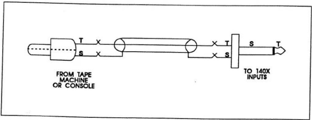
Connecting RCA Phono Plugs to 140X
Output Cable Configurations
1. Connect Audio Outputs
The 140X will drive either balanced or unbalanced loads as long as the cables are wired according to the following figures. Remember, always use a TRS plug for the output of the 140X.
IMPORTANT:

The output amplifiers on the 140X are not designed to drive a short to Ground. NEVER ground the high or low sides of the "To Tape Rec" and "To Console" jacks at any point between the 140X and the next device. While this will not damage the 140X, distortion will increase and you will have level problems.
All outputs are electronically balanced for driving loads of 600Ω or greater. Nominal operating level is +4dBu, and can be set for levels ranging from -24 to +10dBu. Output impedance is 44Ω balanced and 22Ω unbalanced. The output jacks are TRS ¼" phone jacks, Tip Hot (on dbx equipment, Tip = XLR Pin 3).
2. Wire the To Console and To Tape Rec output cables for fully balanced operation or unbalanced operation
Refer to the examples on the following pages. Refer to the type of operation and type of connector you are using.
NOTE: For best hum rejection, start by grounding the shield(s) [Pin 1 on the XLR, Sleeve on a 14 " TRS] only at the output(s). If hum persists, try grounding the shield(s) at the input(s) as well.
3. Check Input/Output Polarity for Balanced Systems (OPTIONAL)
After the 140X has been wired into the system, use a cable checker or ohmmeter to make sure that signal polarity has not been reversed within a cable. Set all four front-panel buttons to OUT.
A. Check that Pin 1 is continuous through Channel A - From Console to the other end of the cable coming from Channel A - To Tape Rec. Check Pins 2 and 3.
B. Repeat for Channel B.
140X Outputs: Fully Balanced Operation

Connecting 140X to XLR Connector
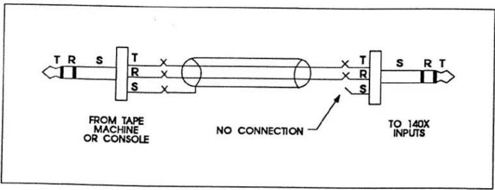
Connecting 140X to 14 " TRS
NOTES for using 1/4" TRS connectors:
- If the 140X is wired into a patchbay, never insert a mono plug into the patchbay.
140X to a Single-Ended Input: "Unbalanced" Operation

Connect 140X to 14 " Mono.
NOTES for using 1/4" connectors:
- If you are using a TRS plug at the tape machine or console, tie the Ring and Sleeve together, and connect the Sleeve to the wire's Shield. This is equivalent to a cable with 14 " Mono plugs on both ends.

Connect 140X to RCA
NOTES for using RCA connectors:
- The Ring conductor is never connected to anything when the 140X is driving single-ended inputs. Leave it floating.
Mounting the 140X in a Rack
1. Mount the 140X "Half-Rack" Unit in a Single Rack Space.
A 140X requires one rack space (height) and 12 rack space (width). It can be mounted above or below anything that doesn't generate excessive heat, since it requires no special ventilation. Mounting ears and a blank half-panel for a single unit are provided. Two 140X units may be mounted side-by-side in one rack space for a total of four channels of simultaneous encode and decode processing.
In addition, all dbx "half-rack" units share a common chassis and mounting scheme. As a result, any dbx Performer Series signal processor (163X Compressor, 263X De-Esser, 463X Over-Easy Noise Gate, or 563X Hiss Reducer) may be mounted next to the 140X to save rack space. The dbx 150X Type I Noise Reduction unit may also be mounted next to the 140X. Hardware for side-by-side mounting is included with each half-rack product. If the rubber feet were used for table top operation, they should be removed at this time.
Caution: Never remove the cover. There are no user-serviceable parts inside, and you run the risk of a fatal electric shock.

To install a single 140X (left or right side)
Refer to Figure 1.
You will need:
1 blank black panel
1 rack ear
1 blank panel adaptor piece
1 3/32" Allen wrench
1 Phillips screwdriver (not included)
4 pan head Phillips screws
2 hex head screws
NOTE: Your 140X assembly kit includes the tools and hardware listed above, except as noted.

natural_image
Technical line drawing of a mechanical assembly with two rectangular components and mounting holes (no text or symbols)Figure 1: Installing the 140X in a Single Rack Space
A. Use a Phillips screwdriver to loosely attach the single rack ear to either side of the 140X with two pan head Phillips screws.
NOTE: If this is the first time the rack ear has been installed, you will be cutting threads as you drive the screws. This is normal.
B. Loosely attach the adaptor piece to the other side of the 140X using two more pan head Phillips screws and a Phillips screwdriver. See note above.
C. Loosely attach the blank panel and adaptor piece using an Allen wrench and two hex head screws.
D. Align everything on a flat surface and tighten the screws with a Phillips screw-driver and the hex wrench.
To install two units side-by-side
Refer to Figure 2.
You will need:
1 joiner assembly (joiner, joiner side pieces)
1 reinforcing plate
2 rack ears
1 3/32" Allen wrench
1 Phillips screwdriver (not included)
4 pan head Phillips screws
4 flat head countersink screws
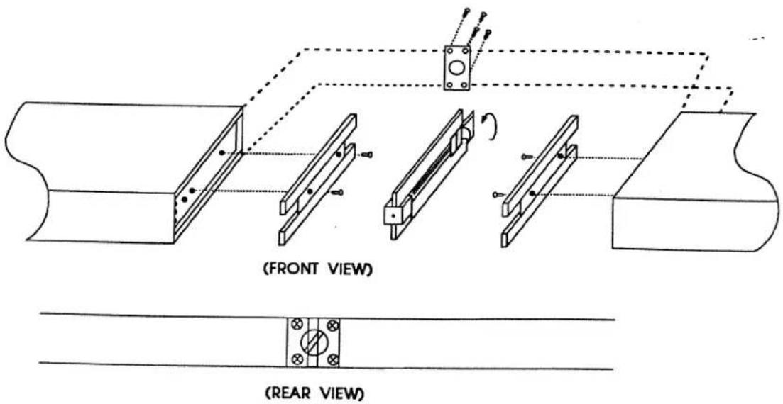
Figure 2: Installing 2 140X Units in a Single Rack Space
NOTE: Your 140X assembly kit includes the tools and hardware listed above, except as noted.
A. Remove the joiner assembly from the assembly kit that was supplied with each unit. Note how the joiner side pieces are held captive by the joiner before you separate them. This is important when it comes time to join the units together. Now separate the joiner side pieces from the joiner by turning the thumbscrew counterclockwise.
B. At this time you will need to designate a "Left" and a "Right" unit.
C. With the left unit facing you, loosely attach a rack ear to the left side of the unit with two pan head Phillips screws. On the right side of the unit, place a joiner side piece into the extruded channel so the holes in the unit align with the holes in the joiner side piece — countersink side up. Secure the joiner side piece with two countersink screws.
NOTE: If this is the first time the rack ear has been installed, you will be cutting threads as you drive the screws. This is normal.
D. Repeat Step "D" with the "Right" unit; swapping right for left with regard to the rack ear mounting and left for right with regard to the joiner side pice mounting.
E. Place the Left and Right units on a flat surface, rear facing, so the joiner side pieces are approximately 2" apart. Take the joiner assembly and loosen the thumbscrew so the sliding catches clear the joiner side-piece cut-outs. Now place the joiner assembly against one of the units with the side piece so it lays flush. (The joiner assembly should be positioned so the thumbscrew is accessible from the rear of the unit.) While holding the joiner assembly in position, slide the other unit over so it mates flush with the joiner assembly and turn the thumbscrew clockwise until it is snug. Do not over-tighten. Both units should now be secured together.
F. Make sure everything is aligned, and tighten the screws on each of the two rack ears.
NOTE: For installations where the two units will be subjected to physical stress (e.g. portable operations), a small OPTIONAL reinforcement plate is included. See steps 1-G through 1-I. If you don't wish to use the reinforcing plate, skip the following steps.
G. Turn the two units so that the back faces you. Remove the four rear cover screws nearest the joiner knob.
H. Place the reinforcing plate over the joiner knob so that the four screw holes line up.
- Replace the four screws, using the slightly longer screws provided in the Accessory Kit.
Maintenance and Tech Support
Maintenance and Troubleshooting
The 140X is an all-solid-state product with components chosen for high performance and excellent reliability. Each 140X is tested, burned in and calibrated at the factory and should require no adjustment of any type throughout the life of the unit. We recommend that your 140X be returned to the factory should circumstances arise which necessitate repair or recalibration. The 140X requires no special preventive maintenance.
Technical Support
If you require technical support, contact dbx customer service. Be prepared to accurately describe the problem. Know the serial number of your 140X — this is printed on a sticker attached to the rear panel.
Telephone: (1) 415/351-3500
or Fax: (1) 415/351-0500
or Telex: 17-1480
or Write:
Customer Service
dbx Professional Products
a division of AKG Acoustics, Inc.
1525 Alvarado Street
San Leandro, CA 94577 USA
Factory Service
Always contact Customer Service before returning a product to the factory for service. Often, a problem is relatively simple and can be quickly fixed after telephone consultation.
Products can be returned to the factory for service only after Customer Service has issued a Return Authorization number. This number flags the returned unit for priority treatment when it arrives on our dock, and ties it to the appropriate information file.
Please refer to the terms of your Limited Two-Year Standard Warranty, which extends to the first end-user. After expiration of the warranty, a reasonable charge will be made for parts, labor, and packing if you choose to use the factory service facility. In all cases, you are responsible for transportation charges to the factory. dbx will pay return shipping if the unit is still under warranty.
Shipping Instructions
Use the original packing material if it is available or a sturdy, double-walled carton no smaller than 12 x 7 x 3 inches (30 x 18 x 8 cm). Place the unit in a plastic bag or wrap to protect the finish, then pack it in the carton with at least 1.5 inches (1 cm) of cushioning on all sides of the unit. Use enough packing to prevent the module from moving during shipment. Seal the carton with 3-inch (8 cm) reinforced fiberglass or polyester sealing tape.
Mark the package with the name of the shipper, and with these words in red:
DELICATE INSTRUMENT, FRAGILE!
Insure the package properly. Ship prepaid, not collect. Do not ship parcel post.
Specifications
(Minimum performance specifications — for single-ended, “unbalanced” operation except as noted)
Effective Noise Reduction: 40dB or more, depending on transmission medium
Frequency Response: 20Hz - 20kHz (±0.5dB 30Hz-20kHz, -1dB at 20Hz)
Dynamic Range: 115dB balanced; 112dB single-ended
Equivalent Input Noise: -82dBu, 20Hz to 20kHz bandwidth, unweighted
Total Harmonic Distortion (THD): 0.1% 100Hz-20kHz, less than 0.5% 30-100Hz
Intermodulation Distortion (IMD) IHF or SMPTE: 0.2%
Maximum Input and Output Levels: 12V; will drive 600Ω to +24dBv balanced, +21dBv single-ended
Input Impedance: Balanced = 75kΩ, Unbalanced = 54.3kΩ,
Output Impedance: Low-impedance (44Ω balanced, 22Ω unbalanced), designed to drive 600Ω or greater
Level Range for Unity Gain (level match): Set at 316mV, adjustable 50mV-2V (-24 to +10dBu)
Controls: Record Level Adjustment, Play Level Adjustment, Encode IN/OUT switch, Decode IN/OUT switch.
Indicators: Power: Red; Record: Green; Play: Green
Power Supply Requirements: 90 - 130VAC, 50/60Hz, Switchable to 220 - 240VAC
Dimensions: Front panel 1U high; (1¼," 4.4 cm) x 8¾"W, 21.3 cm wide; card depth behind panel 7"D, 17.8 cm deep
Notes:
1) Specifications are subject to change.
2) All voltages are RMS (root-mean-square). 0dBu is defined as 0.775V regardless if load impedance. Subtract 2.2 from the dBu figure to convert to dBV (i.e., referred to 1V). When the load impedance is 600 ohms, this particular dBu is also known as "dBm."
3) Dynamic range is defined as the difference between the maximum 1kHz rms signal and unweighted noise. Other noise figures are for 20Hz-20kHz, also unweighted. A-weighting will improve all of these figures by a few dB.
4) Frequency response figures are for pink noise.
5) THD and IMD measurements are for total encode-decode processing. SMPTE IMD is measured with 60 & 7kHz mixed 4:1 IHF (difference tone), IMD is measured with 19 & 20kHz mixed 1:1; output 1V.
6) Inputs and outputs have identical polarity.
- Introduction
- Front Panel
- Rear Panel
- Connecting Your 140X to Your System
- System Connections
- Multi-Channel Connections
- Basic Operation
- Tape Recording: Adjusting Input and Output Levels
- Level Adjustments
- Record Adjust
- Playback Adjust
- Compensating for an Encoded Signal
- Tape Mastering and Alignment Tones
- Other Applications: Adjusting Input and Output Levels
- Type II and Digital Recording
- Specific Applications
- Radio Broadcast
- Television Studio
- Audio Production and Recording Studios
- Understanding dbx Noise Reduction
- Type I
- Type II
- Noise Modulation
- Input Cable Configurations
- Prepare for Audio Input and Output Connections
- Connect Audio Inputs (From Console / From Tape Rec)
- Wire the From Console and From Tape Rec input cables for fully balanced operation or unbalanced operation.
- Output Cable Configurations
- Connect Audio Outputs
- IMPORTANT:
- Wire the To Console and To Tape Rec output cables for fully balanced operation or unbalanced operation
- Check Input/Output Polarity for Balanced Systems (OPTIONAL)
- Mounting the 140X in a Rack
- Mount the 140X "Half-Rack" Unit in a Single Rack Space.
- To install a single 140X (left or right side)
- Refer to Figure 2.
- Maintenance and Tech Support
- Maintenance and Troubleshooting
- Technical Support
- Factory Service
- Shipping Instructions
- DELICATE INSTRUMENT, FRAGILE!
- Specifications
- Notes:
Brand : DBX
Model : 140X
Category : Professional audio equipment