
Novastar MX40 Pro - Projector Chauvet - Free user manual and instructions
Find the device manual for free Novastar MX40 Pro Chauvet in PDF.


| Product Type | LED Moving Head Projector |
| Brand | Chauvet |
| Model | Novastar MX40 Pro |
| Dimensions (LxWxH) | 400 x 300 x 500 mm |
| Weight | 10 kg |
| Power Supply | AC 100-240V, 50/60 Hz |
| Power Consumption | 200 W |
| Light Source | 40W LED |
| Color Wheel | 7 colors + white |
| Gobo Wheel | 7 rotating gobos + open |
| Beam Angle | 9° - 36° motorized zoom |
| Pan/Tilt | 540° pan, 270° tilt |
| Control Protocol | DMX512 (16 channels) |
| Operating Modes | Auto, Sound Active, Master/Slave, DMX |
| Cooling System | Fan cooled |
| Safety Features | Overheat protection, safety cable loop |
| Mounting | M10 rigging points; floor stand or truss |
| Maintenance | Clean lens with soft cloth; periodic ventilation check |
| Spare Parts & Repairability | Replaceable LED module, fuse, and gobo wheel |
| General Information | Professional-grade moving head for stages and events |
Frequently Asked Questions - Novastar MX40 Pro Chauvet
User questions about Novastar MX40 Pro Chauvet
0 question about this device. Answer the ones you know or ask your own.
Ask a new question about this device
Download the instructions for your Projector in PDF format for free! Find your manual Novastar MX40 Pro - Chauvet and take your electronic device back in hand. On this page are published all the documents necessary for the use of your device. Novastar MX40 Pro by Chauvet.
USER MANUAL Novastar MX40 Pro Chauvet
User Manual
Change History
| Document Version | Release Date | Description |
| V1.2.2 | 2023-07-04 | Added descriptions for low latency. |
| V1.2.1 | 2023-03-24 | Added the display mode switching function.Added the brightness overdrive function. |
| V1.2.0 | 2023-01-03 | Added the function of changing the temperature scale.Added a layer scaling mode: fill screen.Support the SNMP and Art-Net protocols. |
| V1.1.1 | 2022-11-18 | Added a table of load capacity per Ethernet port.Added the limitations of some functions. |
| V1.1.0 | 2022-11-07 | Updated the description of the USB port on the front panel.Optimized the description of Ethernet port load capacity. |
| V1.0.0 | 2022-07-09 | First release |
Contents
Change History....i
Contents ...... ii
1 Overview....1
2 Appearance....2
2.1 Front Panel....2
2.2 Rear Panel 2
3 Applications....6
4 UI Introduction ......7
4.1 Home Screen ....7
4.2 Main Menu....9
5 Initial Screen Configuration....10
5.1 Quick Configuration via Front Panel Screen....10
5.1.1 Set Input Source....10
5.1.2 Load Cabinet Config File 11
5.1.3 Configure the Screen Quickly 11
5.2 Free Screen Configuration via VMP 12
6 Display Effect Adjustment....13
6.1 Apply Presets ...... 13
6.2 Set External Input Source Parameters....13
6.2.1 View Input Source Information (HDMI1, HDMI2, HDMI3, DP, SDI)....13
6.2.2 Set Resolution and Frame Rate (HDMI1, HDMI2, HDMI3 and DP only) 13
6.2.3 Adjust Color (HDMI1, HDMI2, HDMI3, DP, SDI) 14
6.2.4 Set HDR Parameters (HDMI1, HDMI2, HDMI3, DP and SDI).... 15
6.3 Set Internal Input Sources....15
6.4 Set Output Parameters....16
6.4.1 Adjust Screen Brightness.... 16
6.4.2 Adjust Gamma and Color Temperature....17
6.4.3 Enable 3D Function....18
6.4.4 Set Low Latency 18
6.4.5 Set Bit Depth 19
6.4.6 Set Sync Source....19
6.5 Set Layers (All-In-One Controller Mode only) 20
7 Device Management....22
7.1 Switch Working Mode....22
7.2 Set a Backup Device 22
7.3 Configure Communication Settings....22
7.4 Enable Mapping ....23
7.5 Control Display Status....23
7.6 Diagnostics....24
7.7 View the Firmware Version....25
7.8 Reset to Factory Settings....25
8 Basic System Settings....26
8.1 Set Language 26
8.2 Set Temperature Scale 26
8.3 Set Session Timeout....26
8.4 View Service Information....27
9 Product Specifications ....28
10 Video Source Specifications 29
11 Ethernet Port Load Capacity 31
1 Overview
The MX40 Pro is a flagship all-in-one LED display controller with 20 Ethernet ports in the brand-new control system COEX series of Xi'an NovaStar Tech Co., Ltd. (hereinafter referred to as NovaStar). This controller integrates video processing and video control into one box and offers rich video input connectors (HDMI 2.0, DP 1.2 and 12G-SDI), 20x Ethernet output ports and 4x 10G optical ports. It can also work with the brand-new software VMP (Vision Management Platform) to provide a better operation and control experience.
This document mainly describes the menu operations on the LCD screen of the controller. For more function operations, see the VMP Vision Management Platform User Manual.
2 Appearance
2.1 Front Panel
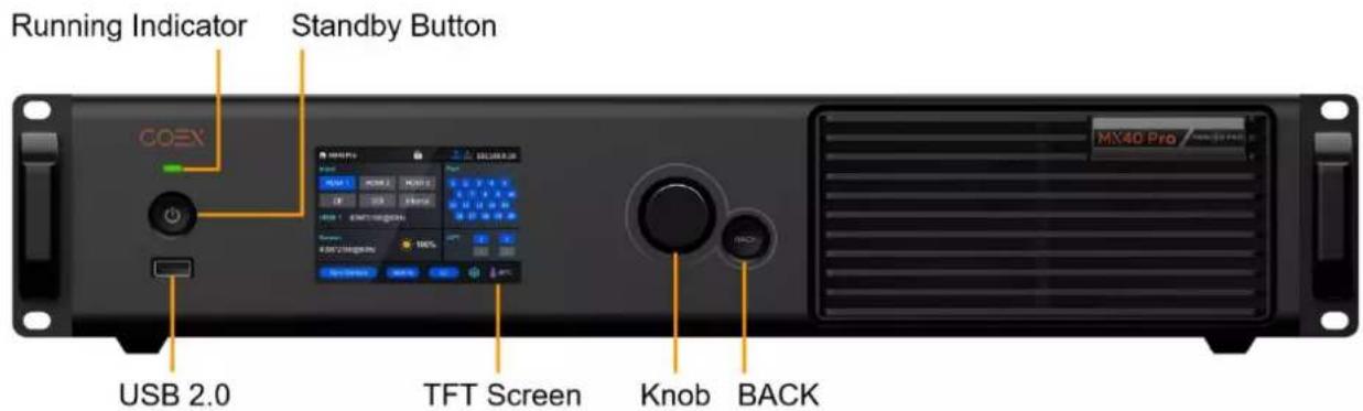
| Name | Description |
| Running Indicator | Solid red: StandbySolid blue: The device is being started.Solid green: The device is running normally.Flashing red: The device is running abnormally. |
| Standby Button | Press the button to power on or power off the device.Hold down the button for 5s or longer to restart the device. |
| USB 2.0 | Connect to a USB drive only to export the device diagnostic result.Only the NTFS and FAT32 file systems are supported. Others are not supported. |
| TFT Screen | A 3.5-inch screen to display the device status, menus, submenus and messages for parameter settings |
| Knob | On the home screen, press the knob to enter the main menu screen.On the main menu screen, rotate the knob to select a menu item or adjust the parameter value. Press the knob to confirm the operation.Hold down the knob and BACK button simultaneously for 5s or longer to lock or unlock the buttons. |
| BACK | Go back to the previous menu or cancel the current operation. |
2.2 Rear Panel

| Inputs | |||
| Type | Qty | Description | |
| HDMI 2.0-1 IN | 1 | Resolutions | Max resolution: 4096×2160@60Hz/8192×1080@60Hz (Forced)Min resolution: 800×600@60Hz |
| Max width/height (Forced) | Max width: 8192 pixels (8192×1080@60Hz)Max height: 8192 pixels (1080×8192@60Hz) | ||
| Frame rates | 23.98 / 24 / 25 / 29.97 / 30 / 47.95 / 48 / 50 / 59.94 / 60 / 71.93 / 72 / 75 / 100 / 119.88 / 120 / 143.86 / 144 / 240 Hz | ||
| HDR | Support HDR10 and comply with the SMPTE ST 2084 and SMPTE ST 2086 standards.Support HLG. | ||
| EDID management | Support standard resolutions, up to 3840×2160@60Hz.Support custom input resolutions. | ||
| HDCP | HDCP 2.2 compliant, backwards compatible | ||
| Interlaced signal inputs | Not supported | ||
| HDMI 2.0-2 IN | 1 | Resolutions | Max resolution: 4096×2160@60Hz/8192×1080@60Hz (Forced)Min resolution: 800×600@60Hz |
| Max width/height (Forced) | Max width: 8192 pixels (8192×1080@60Hz)Max height: 7680 pixels (1080×7680@60Hz) | ||
| Frame rates | 23.98 / 24 / 25 / 29.97 / 30 / 47.95 / 48 / 50 / 59.94 / 60 / 71.93 / 72 / 75 / 100 / 119.88 / 120 / 138.86 / 144 / 240 Hz | ||
| HDR | Support HDR10 and comply with the SMPTE ST 2084 and SMPTE ST 2086 standards.Support HLG. | ||
| EDID management | Support standard resolutions, up to 3840×2160@60Hz.Support custom input resolutions. | ||
| HDCP | HDCP 2 . 2 compliant, backwards compatible | ||
| Interlaced signal inputs | Not supported | ||
| HDMI 2.0-3 IN | 1 | Resolutions | Max resolution: 4096×2160@60Hz/8192×1080@60Hz (Forced)Min resolution: 800×600@60Hz |
| Max width/height(Forced) | Max width: 8192 pixels (8192×1080@60Hz)Max height: 7680 pixels (1080×7680@60Hz) | ||
| Frame rates | 23.98 / 24 / 25 / 29.97 / 30 / 47.95 / 48 / 50 / 59.94 / 60 / 71.93 / 72 / 75 / 100 / 119.88 / 120 / 143.86 / 144 / 240 Hz | ||
| HDR | Support HDR10 and comply with the SMPTE ST 2084 and SMPTE ST 2086 standards.Support HLG. | ||
| EDIDmanagement | Support standard resolutions, up to 3840×2160@60Hz.Support custom input resolutions. | ||
| HDCP | HDCP 2.2 compliant, backwards compatible | ||
| Interlaced signalinputs | Not supported | ||
| DP 1.2 | 1 | Resolutions | Max resolution: 4096×2160@60Hz/8192×1080@60Hz (Forced)Min resolution: 800×600@60Hz |
| Max width/height(Forced) | Max width: 8192 pixels (8192×1080@60Hz)Max height: 8192 pixels (1080×8192@60Hz) | ||
| Frame rates | 23.98 / 24 / 25 / 29.97 / 30 / 47.95 / 48 / 50 / 59.94 / 60 / 71.93 / 72 / 75 / 100 / 119.88 / 120 / 138.86 / 144 / 240 Hz | ||
| HDR | Support HDR10 and comply with the SMPTE ST 2084 and SMPTE ST 2086 standards.Support HLG. | ||
| EDIDmanagement | Support standard resolutions, up to 3840×2160@60Hz.Support custom input resolutions. | ||
| HDCP | HDCP 1.3 compliant | ||
| Interlaced signalinputs | Not supported | ||
| 12G-SDI IN | 1 | Standards | Support ST-2082 (12G), ST-2081 (6G), ST-424 (3G) and ST-292 (HD) standard video inputs.Support 3G-Level A/Level B (DS mode). |
| Resolutions | Max resolution: 4096×2160@60Hz | ||
| Frame rates | Support frame rates up to 60 Hz. | ||
| HDR | Support HDR10 and comply with the SMPTE ST 2084 and SMPTE ST 2086 standards.Support HLG. | ||
| Others | Belden 12G SDI standard cables are recommended. Cables up to 50 meters are supported. | ||
| Outputs | ||
| Type | Qty | Description |
| 1-20 | 20 | Gigabit Ethernet output ports. Support hot backup between Ethernet ports.Max device load capacity: 9 million pixelsThe maximum load capacity per Ethernet port is as follows. For details, see chapter 11 Ethernet Port Load Capacity.- 8bit@60Hz: 659,722 pixels- 10bit@60Hz: 494,791 pixels (available only with the A10s Pro receiving card)- 10bit/12bit@60Hz: 329,861 pixels |
| OPT 1-4 | 4 | 10G optical output portsOPT 1 transmits the data of Ethernet ports 1 to 10.OPT 3 is the copy channel of OPT 1.OPT 2 transmits the data of Ethernet ports 11 to 20.OPT 4 is the copy channel of OPT 2. |
| HDMI 2.0-1 LOOP | 1 | HDMI loop through. Up to 8 devices can be cabled in one loop. |
| HDMI 2.0-2 LOOP | 1 | |
| HDMI 2.0-3 LOOP | 1 | |
| 12G-SDI LOOP | 1 | SDI loop through. Up to 8 devices can be cabled in one loop. |
| SPDIF OUT | 1 | A digital audio output (Reserved) |
| Controls | ||
| Type | Qty | Description |
| ETHERNET | 2 | Gigabit Ethernet control ports. Support TCP/IP protocol and star topology.They have the same functions without priority and order, and can be connected to VMP software. No switch or router is needed to deploy multiple devices on the same LAN via device cascading as the network switching function is already built in. Up to 20 MX40 Pro devices can be cascaded. |
| GENLOCK | 1 | A pair of Genlock signal connectors. Support Bi-Level and Tri-Level.IN: Accept the sync signal.Loop: Loop the sync signal.For standard Genlock signal generators, up to 20 MX40 Pro devices can be cascaded. |
| AUX | 1 | An auxiliary port that connects to the central control device (RS232) (Reserved) |
| Power | ||
| 100-240V~, 50/60Hz, 1.5A | 1 | An AC power input connector and switch |

Note
The maximum input resolution and maximum width and height of HDMI and DP connectors must be obtained by setting the graphics card.
3 Applications
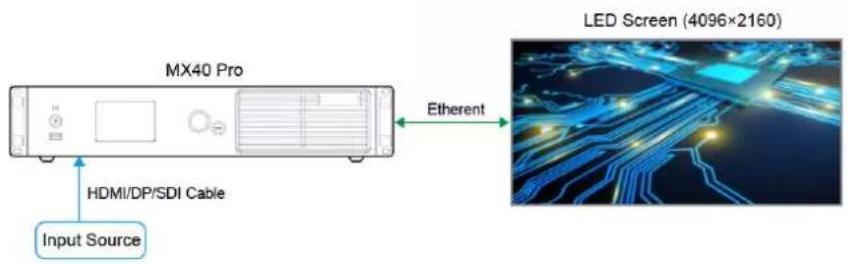
The MX40 Pro has two typical application scenarios as shown below. In those application examples, the LED screen size is 4096 × 2160 .
Application 1: Synchronous Mosaic
Application 2: Long-Distance Transmission via OPT Ports
![graph LR A["Input Source"] --> B["MX40 Pro"] B --> C["Fiber (OPT1)"] B --> D["Fiber (OPT2)"] C --> E["Fiber Converter"] D --> F["Fiber Converter"] E --> G["LED Screen (4096×2160)"] F --> G style A fill:#f9f,stroke:#333 style G fill:#bbf,stroke:#333](/content/2026/05/1061982/images/4e4b95426c2559f4ab4b1c0de5e9dcef22c55daa2e7ead21924d8dc90de2d682.jpg)
4 UI Introduction
4.1 Home Screen
After the device is powered on, the home screen showing device related information is displayed as follows.
Figure 4-1 Home screen
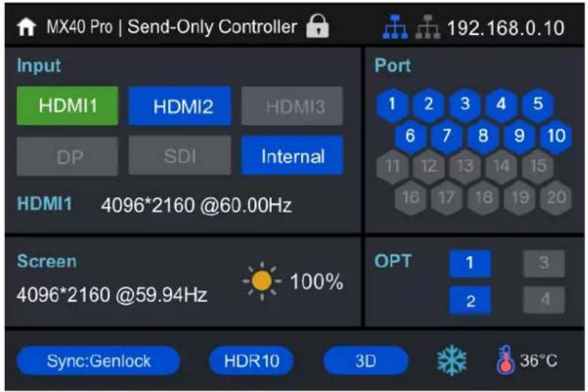
The home screen is shown in Figure 4-1 and the home screen descriptions are shown in Table 4-1.
Table 4-1 Home screen descriptions
| Area | Content | Description |
| Top line | MX40 Pro | The device nameThe name can be changed in VMP software. |
| Send-Only Controller | The device working modeAll-In-One Controller: The video processing and sending functions are available.Send-Only Controller: Only the video sending function is available.For related operations, please refer to 7.1 Switch Working Mode. | |
 | The device button lock statusWhen the icon displayed: The buttons are locked.When the icon not displayed: The buttons are unlocked.Hold down the knob and BACK button simultaneously for 5s or longer to lock or unlock the buttons. | |
 | The connection status of the Ethernet portsBlue: ConnectedGray: Disconnected | |
| 192.168.0.10 | The device IP addressFor related operations, please refer to 7.3 Configure Communication Settings Set an IP Address. | |
| Input | HDMI1, HDMI2, HDMI3, DP, SDI, Internal | The device input source type and statusGreen: The signal is accessed normally and used.Blue: The signal is accessed normally, but not used.Red: The signal is not accessed, or the accessed signal is abnormal.Gray: The signal is abnormal and not used.For related operations in the Send-Only Controller working mode, please refer to 5.1.1 Set Input Source. |
| HDMI14096*2160@60.00Hz | The resolution and frame rate of the currently available input sourceIf multiple input sources are available, the resolution and frame rate of each input source will be displayed one by one. If the input is used by the layer, the layer number will be displayed below.For related operations, please refer to 6.2.2 Set Resolution and Frame Rate (HDMI1, HDMI2, HDMI3 and DP only). | |
| Screen | 4096*2160@59.94Hz | The screen resolution and frame rate |
 | The screen brightnessFor related operations, please refer to 6.4.1 Adjust Screen Brightness. | |
| Port | 1–20 | The statuses of the Ethernet portsBlue: ConnectedGray: Disconnected |
| OPT | 1–4 | The statuses of the OPT portsBlue: ConnectedGray: Disconnected |
| Bottom line | Sync: Genlock | The sync signal currently used and the signal statusSync: Active Input: Sync with the frame rate of the current input sourceSync: Genlock: Sync with the frame rate of the Genlock signalSync: Internal: Sync with the frame rate of the internal clock of the deviceColor code:Blue: The signal is normal.Red: The signal is abnormal.For related operations, please refer to 6.4.6 Set Sync Source. |
| HDR10 | The format of the dynamic rangeFor-related operations, please refer to 6.2.4 Set HDR Parameters (HDMI1, HDMI2, HDMI3, DP and SDI). | |
| 3D | The 3D function statusThe icon displayed: The 3D function is turned on.The icon not displayed: The 3D function is turned off.For related operations, please refer to 6.4.3 Enable 3D Function. | |
| The output display status. For related operations, please refer to 7.5 Control Display Status.: The display is frozen.: The display is blacked out | ||
| [3K00] | The temperature inside the chassis |
4.2 Main Menu
On the home screen, press the knob to enter the main menu screen. When the device working mode is All-In-One Controller, the main menu is shown in Figure 4-2. When the device working mode is Send-Only Controller, the Layer Settings menu is not displayed.
Figure 4-2 Main menu

5 Initial Screen Configuration
If the LED screen, cabinets, data flow and the number of cabinets loaded by Ethernet ports can meet the following requirements, you can configure the screen via the device front panel menu; otherwise, screen configuration in VMP will be your ideal choice.
- Screen: The LED screen must be a regular screen.
● Cabinet: The cabinets must be regular ones of the same size, and function well. - Data flow: The data must run in the same way for all Ethernet ports and the data flow must be one of the followings. The starting position of the data flow is the first cabinet of Ethernet port 1, and the connections are made in sequence according to the serial number of the Ethernet port.
![graph TD A["2"] --> B["1"] B --> C["5"] C --> D["1"] D --> E["5"] E --> F["2"] F --> G["1"]](/content/2026/05/1061982/images/fcb84de1f6d516c5704dcbd9a7a655e899e4c9579efacb0f865062bc6444d0f9.jpg)
- Number of cabinets loaded by Ethernet ports: If n ports are used to load the cabinets, the number of cabinets loaded by each of the first (n - 1) ports must be the same and the integral multiple of the number of cabinet rows or columns, and it must be greater than or equal to the number of cabinets loaded by the last port.
5.1 Quick Configuration via Front Panel Screen
5.1.1 Set Input Source
Select the desired input source and complete the related settings, such as resolution and frame rate. If the resolutions of the input source and screen are the same, the image can be displayed pixel to pixel. A lower frame rate may result in image flickering, while a higher frame rate helps stabilize the display image.

Input source settings are required for screen configuration in the Send-Only Controller working mode and not required in the All-In-One Controller mode.
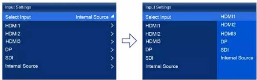
Step 1 On the main menu screen, choose Input Settings > Select Input to select a video source.
Figure 5-1 Select input source
Step 2 Perform the corresponding operations for the input source according to the input source type. For the SDI sources, please skip this step.
• External input sources (HDMI1, HDMI2, HDMI3, DP)

a. Choose input source > EDID. The input source is HDMI1, HDMI2, HDMI3 or DP.
b. Set Mode to Custom or Standard, and then set the resolution and frame rate.
Custom: Set the resolution manually.
Standard: Select the desired resolution from the drop-down options.
c. After the settings are done, click Apply.
- Internal sources

a. Choose Internal Source > Image, and then select a static picture or a motion picture.
b. When the relevant parameters of the image are displayed, set the parameters according to your actual needs; otherwise, please skip this step.
c. Press the BACK button to go back to the upper-level menu and select Resolution.
d. Set Mode to Custom or Standard, and then set the resolution and frame rate.
e. After the settings are done, click Apply.
5.1.2 Load Cabinet Config File
When the cabinet cannot display images normally, send the cabinet configuration file (.rcfgx) to the cabinet and save it to let the cabinet display image normally. Before the operation, please import cabinet configuration file with VMP.
Step 1 On the main menu screen, choose Screen Configuration > Send Cabinet Config File.
Figure 5-2 Send cabinet config file
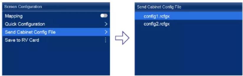
Step 2 Select the target configuration file.
Step 3 Select Yes in the displayed dialog box.
After the configuration file is successfully sent, a message appears on the menu screen and then then you will automatically return to configuration file screen.
Step 4 Press the BACK button to go back to the upper-level menu.
Step 5 Select Save to RV Card.
Step 6 Select Yes in the displayed dialog box.
After the configuration file is successfully saved, a message appears on the menu screen.
5.1.3 Configure the Screen Quickly
Set the screen configuration parameters to quickly complete the cabinet connection, so that the LED screen can display the input source image normally.
Step 1 On the main menu screen, choose Screen Configuration > Quick Configuration.
Figure 5-3 Quick configuration
![graph LR A["Screen Configuration"] --> B["Quick Configuration"] B --> C["Switch"] C --> D["Screen Configuration"] D --> E["Quick Configuration"] E --> F["Output: Cabinet Row Qty, Cabinet Column Qty, Port 1 Cabinet Qty, Data Flow (Front View), H Offset, V Offset"]](/content/2026/05/1061982/images/31211e897b35b8dc0f26c1885398427d686a10e2acdbf7be45612ac91f5b7347.jpg)
Step 2 Select Yes in the displayed dialog box.
Step 3 Set screen configuration parameters as required.
• Cabinet Row Qty: Set the quantity of cabinet rows.
• Cabinet Column Qty: Set the quantity of cabinet columns.
- Port 1 Cabinet Qty: Set the quantity of the cabinets loaded by Ethernet port 1.
● Data Flow (Front View): Select the data flow for the cabinets loaded by Ethernet port 1.
• H Offset: Set the horizontal offset of the displayed image.
• V Offset: Set the vertical offset of the displayed image.
5.2 Free Screen Configuration via VMP
The VMP software can be used to configure either the regular screens or complex screens, and supports free wiring of the cabinets, plus the ability of calculating the used load capacity according to the cabinets that are actually loaded. For the details of performing the free screen configuration, please refer to VMP Vision Management Platform User Manual.
6 Display Effect Adjustment
6.1 Apply Presets
Apply a saved preset in VMP to the device to quickly complete display effect adjustment.
Step 1 On the main menu screen, select Preset.
The saved presets in VMP is displayed on the menu screen, as shown in Figure 6-1.
Figure 6-1 Presets
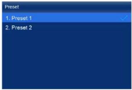
Step 2 Select a preset.
6.2 Set External Input Source Parameters
6.2.1 View Input Source Information (HDMI1, HDMI2, HDMI3, DP, SDI)
View the attribute values of the external input source, including the resolution, frame rate, bit depth, color gamut, etc.
Step 1 On the main menu screen, choose Input Settings > input source > Infoframe. The input source is HDMI1, HDMI2, HDMI3, DP or SDI.
Figure 6-2 Input source information

When the device working mode is All-In-One Controller, the Select Input menu is not displayed.
Step 2 View the input source information.
6.2.2 Set Resolution and Frame Rate (HDMI1, HDMI2, HDMI3 and DP only)
Set the resolution and frame rate of the external input source. If the resolutions of the input source and screen are the same, the image can be displayed pixel to pixel. A lower frame rate may result in image flickering, while a higher frame rate helps stabilize the display image.
Step 1 On the main menu screen, choose Input Settings > input source > EDID. The input source is HDMI1, HDMI2, HDMI3 or DP.
Figure 6-3 EDID

When the device working mode is All-In-One Controller, the Select Input menu is not displayed.
Step 2 Set Mode to Custom or Standard, and then set the resolution and frame rate.
- Custom: Set the resolution manually.
- Standard: Select the desired resolution from the drop-down options.
Step 3 After the settings are done, click Apply.
6.2.3 Adjust Color (HDMI1, HDMI2, HDMI3, DP, SDI)
Set the infoframe override parameters of the external input source and adjust the color. The override parameter will be used in the calculation of color adjustment. If the value of this parameter is not set manually, the value that comes with the input source will be used.
Step 1 On the main menu screen, choose Input Settings > input source > EDID. The input source is HDMI1, HDMI2, HDMI3, DP or SDI.
Figure 6-4 Infoframe override
![graph LR A["Input Settings"] --> B["Select Input HDMI1"] B --> C["HDMI1 >"] B --> D["HDMI2 >"] B --> E["HDMI3 >"] B --> F["DP >"] B --> G["SDI >"] B --> H["Internal Source >"] C --> I["→"] D --> I E --> I F --> I G --> I H --> I I --> J["→"] J --> K["Infoframe Override"] K --> L["HDR Auto >"] K -->…](/content/2026/05/1061982/images/5638727f56d9693c49a279fadab6ba7b883f1cd4f0919e5353a5bc69b2001282.jpg)
When the device working mode is All-In-One Controller, the Select Input menu is not displayed.
Step 2 Set the override parameters as required.
Select Auto and the device will read the attribute value that comes with the input source.
Step 3 Press the BACK button to go back to the upper-level menu.
Step 4 Select Color Adjustment.
Step 5 Set the related parameters.
| Parameter | Description |
| Black Level | It is used to adjust the brightness of the dark areas of the image. The smaller the value, the darker the dark part of the screen. |
| Contrast | It is used to adjust the brightness of the highlight areas of the image. The greater the value, the brighter the highlight part of the screen.Contrast and black level together affect the overall contrast of the image. |
| Saturation | It is used to adjust the color purity of the image. The greater the value, the more vivid the color. |
| Hue | It is used to adjust the color effect of the displayed image color. |
| Red Shadow/Green Shadow/Blue Shadow | It is used to adjust the brightness of the dark areas of the image. The principle is the same as that of black level, but only the RGB components are adjusted. |
| Red Highlight/Green Highlight/Blue Highlight | It is used to adjust the brightness of the highlight areas of the image. The principle is the same as that of contrast, but only the RGB components are adjusted. |
6.2.4 Set HDR Parameters (HDMI1, HDMI2, HDMI3, DP and SDI)
Set the parameters used during the process of parsing HDR video sources.
Step 1 On the main menu screen, choose Input Settings > input source > HDR. The input source is HDMI1, HDMI2, HDMI3, DP, or SDI.
Figure 6-5 HDR
![graph LR A["Input Settings"] --> B["Select Input HDMI1"] B --> C["HDMI1"] C --> D["HDMI2"] D --> E["HDMI3"] E --> F["DP"] F --> G["SDI"] G --> H["Internal Source"] I["HDMI1"] --> J["EDID"] J --> K["Color Adjustment"] K --> L["Infoframe"] L --> M["Infoframe Override"] M --> N["HOR"] N --> O["Auto"] P…](/content/2026/05/1061982/images/864233b1c957f1dad78c85c12e0405904fe361b059119046ef460d99e32f57bb.jpg)
When the device working mode is All-In-One Controller, the Select Input menu is not displayed.
Step 2 Select HDR and select the HDR format from the listed options.
Select Auto and the device will read the attribute value that comes with the input source.
Step 3 Select HDR10 Parameters to complete the related settings. If the HDR format is SDR here, no parameters need to be set.
HDR-related parameters include:
- PQ mode: The mapping method of video source brightness.
- ST2084 (PQ): This mode 1:1 maps the brightness of the video source. The part that exceeds the maximum screen brightness will still be adjusted to the maximum screen brightness.
- ST2086 (Linear mapping): This mode linearly maps the brightness of the video source. It globally adjusts the video source brightness according to the maximum screen brightness to ensure that the ratio of the brightness of the entire source content remains unchanged.
- MaxCLL Override: When the MaxCLL Override switch is ☐, the MaxCLL parameter takes effect.
● MaxCLL: Override the maximum video source brightness and adjust the brightness to a specified value.
To restore the parameters to the defaults, select Reset.
Note
The HDR function supports automatic parsing and manual setting. The properties of 12G-SDI sources, DP1.2 sources and non-standard HDR sources can be manually set to HDR properties.
Using the HDR function reduces the MX40 Pro load capacity by less than half if the MX40 Pro works with the A10s Pro receiving card. For details, see 11 Ethernet Port Load Capacity.
6.3 Set Internal Input Sources
Select the internal source stored in the device and set the related parameters for screen testing and troubleshooting.
Step 1 On the main menu screen, choose Input Settings > Internal Source > Image.
Figure 6-6 Internal source

When the device working mode is All-In-One Controller, the Select Input menu is not displayed.
Step 2 Select a static picture or a motion picture.
Step 3 When the relevant parameters of the image are displayed, set the parameters according to your actual needs; otherwise, please skip this step.
Step 4 Press the BACK button to go back to the upper-level menu and select Resolution.
Step 5 Set Mode to Custom or Standard, and then set the resolution, frame rate and bit depth.
Figure 6-7 Resolution parameters

- Custom: Set the resolution manually.
- Standard: Select the desired resolution from the drop-down options.
Step 6 After the settings are done, click Apply.
6.4 Set Output Parameters
6.4.1 Adjust Screen Brightness
Adjust and save the screen brightness.
Step 1 On the main menu screen, select Screen Brightness and press the knob to let the brightness value become editable.
Figure 6-8 Screen brightness (the Send-Only Controller mode as example)

Step 2 Rotate the knob to adjust the brightness to the target value, and then press the knob to confirm.
Step 3 Choose Screen Configuration > Save to RV Card.
www.novastar.tech
Figure 6-9 Save to RV card

Step 4 Select Yes in the displayed dialog box.
After the brightness value is successfully saved, a message appears on the menu screen.
6.4.2 Adjust Gamma and Color Temperature
Adjust and save the Gamma and color temperature.
Step 1 On the main menu screen, choose Advanced Functions > LED Screen Color.
Figure 6-10 LED screen color

Step 2 Adjust the Gamma value.
- Select Gamma and press the knob to let the value become editable.
- Rotate the knob to adjust the Gamma to the target value, and then press the knob to confirm.
Step 3 Adjust the color temperature value.
- Select Color Temperature and press the knob to let the value become editable.
- Rotate the knob to adjust the temperature to the target value, and then press the knob to confirm.
If you want to restore the parameters to the defaults, select Reset.
Step 4 Press the BACK button to go back to the main menu, and then choose Screen Configuration > Save to RV Card.
Figure 6-11 Save to RV card
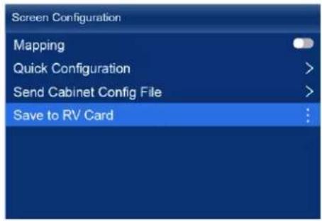
Step 5 Select Yes in the displayed dialog box.
After the values are successfully saved, a message appears on the menu screen.
6.4.3 Enable 3D Function
Turn on the 3D function and set the related parameters.
Step 1 On the main menu screen, choose Advanced Functions > 3D.
Figure 6-12 3D

Step 2 Turn on the 3D function by setting the 3D switch to

Step 3 Set the related parameters.
- Video Source Format: Set the format of the 3D video source. Set the format to SBS, TAB or Frame SEQ according to the format of the accessed video source.
- Right Eye Start: Set the start position of the right eye image. When the video source format is SBS or TAB, and the left and right eye images are provided, this parameter can be set.
- Eye Priority: Set which image is sent first, the right eye image or the left eye image. Wear the 3D glasses to watch the display. If the display is abnormal, set the parameter value to the other one. If the display is normal, the setting is done.
- 3rd Emitter: When a third-party 3D signal emitter is used, set the switch to .
- Emitter Delay: Set the delay time of sending the synchronization signal from the 3D signal emitter to the 3D glasses. This setting ensures that the switching between left and right eye images of the 3D glasses is in sync with the switching between the left and right eye images on the display. This parameter applies to both the NovaStar and third-party emitters.
Note
To use the 3D function, specified 3D glasses are needed. For details, please contact NovaStar technical support.
6.4.4 Set Low Latency
The low latency function is used to reduce the delay at the controller, or increase the latency when the device works with high-latency equipment.
Step 1 On the main menu screen, choose Advanced Functions > Output Settings.
Figure 6-13 Low latency

Step 2 Perform any of the following operations as required.
- Enable low latency
Set the Low Latency switch to enable the low latency function.
- Set additional frame latency
a. Select Additional Frame Latency and press the knob to let the value become editable.
b. Rotate the knob to adjust the parameter to the target value, and then press the knob to confirm.

Note
- When low latency is enabled, the sync source cannot be set to Genlock.
- The latency at the controller is 0 frame (less than 1 ms) in Send-Only Controller working mode and 1 frame in All-In-One Controller working mode.
- To enable low latency, please make sure all Ethernet ports load the cabinets vertically and share the same Y coordinate. Free screen configuration (for example, Ethernet port 2 loads cabinets horizontally, or its Y coordinate is different from that of Ethernet port 1) will reduce the load capacity.
![graph TD A["Port 1"] --> B["LED Display"] C["Port 2"] --> B D["Port 3"] --> B E["Port n"] --> B B --> F["......"]](/content/2026/05/1061982/images/3a2a483c6113a0c24c6d0466d20c6de143329d5e25fefdc13d406ddc042994ab.jpg)
6.4.5 Set Bit Depth
Set the output bit depth of the input source.
Step 1 On the main menu screen, choose Advanced Functions > Output Settings.
Figure 6-14 Bit depth

Step 2 Select Bit Depth and then select the desired bit depth value from the drop-down options.
If Auto is selected, the output bit depth is the same as the input bit depth.
6.4.6 Set Sync Source
Select a synchronization signal for the display frame rate and set the phase offset.
Step 1 On the main menu screen, choose Advanced Functions > Output Settings > Sync.
Figure 6-15 Sync

Step 2 Select Sync Source and then select the desired sync source from the drop-down options.
● Active Source: Sync with the frame rate of the active source.
- Genlock: Sync with the frame rate of the Genlock signal.
- Internal: Sync with the frame rate of the controller's internal clock. When this option is selected, a related parameter Frame Rate is displayed. You can select a value from its drop-down options.
Step 3 Press the BACK button to go back to the upper level menu.
Step 4 Select Phase Offset.
Step 5 Choose Adjustment Mode and then select the desired mode from the drop-down options.
- Off: Turn off the phase offset function.
● Angle: The related parameter Angle can be set.
• Fraction: The related parameter Fraction can be set. - Absolute: The related parameters Lines and Pixels can be set when the sync source is Active Source.

Note
When the sync source is set to Genlock, low latency cannot be enabled.
6.5 Set Layers (All-In-One Controller Mode only)
When the device working mode is All-In-One Controller, set the canvas size and the layers (up to 4) on the canvas.
Step 1 On the main menu screen, select Layer Settings.
Figure 6-16 Layer settings
| Layer Settings | |
| Canvas Size (Max: 61.04Hz) | 4096 * 2160 |
| Layer 1 | Off > |
| Layer 2 | Off > |
| Layer 3 | Off > |
| Layer 4 | Off > |
Step 2 Select Canvas Size to enable the value editing status. Rotate the knob to change the value and press the knob to confirm the value.
Step 3 Select a layer and set the related parameters.
• Status: Turn on or off the layer.
- Input Source: Select an input source.
On the home screen, the number of the layer that is using this input source is displayed in the input source information area.
- Scaling Mode: Set the scaling mode.
- Custom: Customize the width and height.
- Pixel to Pixel: Same as the width and height of the input source
- Snap to Canvas: Same as the width and height of the canvas
- Fill Screen: Same as the width and height of the screen
-
Width: Set the layer width.
• Height: Set the layer height. -
H Position: Set the horizontal coordinate (X) of the layer on the canvas.
• V Position: Set the vertical coordinate (Y) of the layer on the canvas. - Priority: Set the Z coordinate of the layer on the canvas. The greater the value, the higher priority.
- Crop: Turn on or off input crop and set the crop size and position.
- Border: Turn on or off layer border and set the border thickness and color.
Step 4 If necessary, select other layers and set the related parameters.
7 Device Management
7.1 Switch Working Mode
Set the device working mode to All-In-One Controller or Send-Only Controller.
Step 1 On the main menu screen, choose System Settings > Working Mode.
Figure 7-1 Working mode

Step 2 Select All-In-One Controller or Send-Only Controller.
Step 3 Select Yes in the displayed dialog box.
7.2 Set a Backup Device
Specify a backup device for the current device so that the backup device can take over the primary device when it fails.
Step 1 On the main menu screen, choose Advanced Functions > System Backup > Select Backup Device.
Figure 7-2 System backup
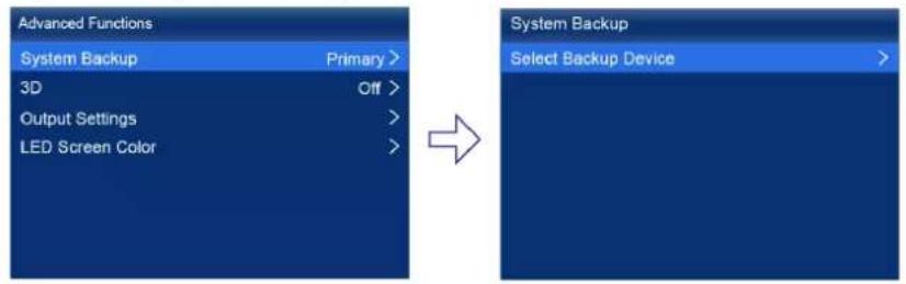
Step 2 Select a device from the devices found.
Step 3 Select Yes in the displayed dialog box.
A prompt will be displayed after the operation is successful.
7.3 Configure Communication Settings
Set an IP Address
Manually set a static IP address for the device or set up the device to automatically obtain an IP address.
Step 1 On the main menu screen, choose Communication Settings > Network Settings.
Figure 7-3 Network settings

Step 2 Choose Mode and then select a mode from the drop-down options.
- Manual: Manually set a static IP address for the device.
• Auto: The device automatically obtains an IP address.
Step 3 If the manual mode is selected, set an IP Address, Subnet Mask and Default Gateway and select Apply. If the automatic mode is selected, this step is not required.
If you want to reset the IP address to the default, select Reset.
Set the Protocol Switch
Set the SNMP and Art-Net protocol switch status.

Note
For details, see the SNMP Protocol Instructions and Art-Net Protocol Instructions.
7.4 Enable Mapping
After the Mapping function is enabled, cabinets can display some information, such as the Ethernet port number and receiving card number, allowing users to easily obtain the locations and connection topology of receiving cards.
Step 1 On the main menu screen, choose Screen Configuration > Mapping.
Figure 7-4 Mapping

Step 2 Enable the Mapping function by toggling on this switch.
7.5 Control Display Status
Set the display loaded by the controller to a black screen or frozen status.
Step 1 On the main menu screen, choose Display Control.
Figure 7-5 Display control

Step 2 Select a display status as required.
• Normal: Display the normal output screen.
- Freeze: Make the output screen always display the current frame. The input source is played normally.
- Blackout: Make the output screen go black. The input source is played normally.
7.6 Diagnostics
Perform device diagnostics, then view and export the result.
Step 1 On the main menu screen, choose System Settings > Diagnostics.
Figure 7-6 Diagnostics

Step 2 Select Yes in the displayed dialog box.
After the diagnostics operation is complete, the diagnostic result will be displayed.
Step 3 Select Close to close the dialog box and the screen as shown in Figure 7-7 is displayed.
Figure 7-7 After diagnostics
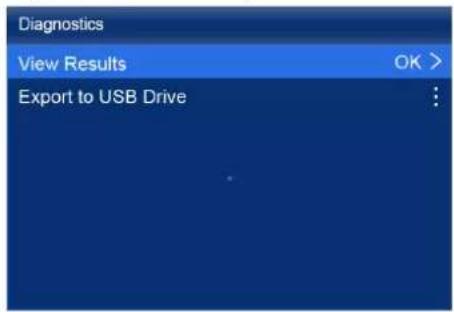
Step 4 Do any of the following as required.
• View the diagnostic results
Select View Results to enter the report page and view the results.
● Export the diagnostic result to a USB drive
a. Insert the USB drive to the USB port on the front panel of the device.
b. Select Export to USB Drive.
A prompt will be displayed after the operation is successful.
7.7 View the Firmware Version
View the current firmware program version of the device.
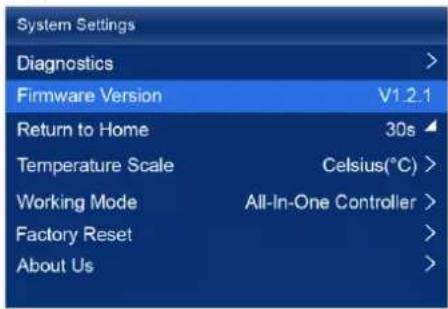
Step 1 On the main menu screen, select System Settings.
Step 2 View the current firmware program version next to Firmware Version.
Figure 7-8 Firmware version
7.8 Reset to Factory Settings
Reset part or all of the device data to the factory settings.
Step 1 On the main menu screen, choose System Settings > Factory Reset.
Figure 7-9 Factory reset

Step 2 Do any of the following according to the data you want to reset.
- Reset part of the data
Reset all the data except the imported files, network parameters, language settings, and device name.
a. Select Keep User Data.
b. Select Yes in the displayed dialog box.
The device restarts automatically while the data is being reset.
- Reset all the data (This action cannot be undone.)
Reset all the data to factory settings.
a. Select Reset All.
b. Select Yes in the displayed dialog box.
The device restarts automatically while the data is being reset.
8 Basic System Settings
8.1 Set Language
Change the system language of the device.
Step 1 On the main menu screen, select 番音/Language.
Step 2 Choose English or 中文 as required.
Figure 8-1 Language

Change the system temperature scale of the device.
Step 1 On the main menu screen, choose System Settings > Temperature Scale.
Step 2 Select Celsius(°C) or Fahrenheit(°F) as needed.
Figure 8-2 Temperature scale

Figure 8-3 Session timeout value
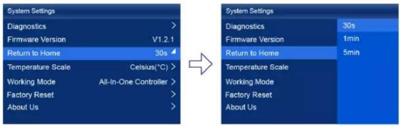
Step 2 Select 30s, 1min or 5min from the drop-down options as required.
8.4 View Service Information
View the service information of NovaStar, allowing users to ask questions and give feedback.
Step 1 On the main menu screen, choose System Settings > About Us.
Figure 8-4 About us

Step 2 View the official website, technical support email address and service hotline of NovaStar.
9 Product Specifications
| Electrical Specifications | Power input | 100-240V~, 50/60Hz, 1.5A |
| Max power consumption | 95 W | |
| Operating Environment | Temperature | -20° C to +50° C |
| Humidity | 0% RH to 80% RH, non-condensing | |
| Storage Environment | Temperature | -30° C to +80° C |
| Humidity | 0% RH to 95% RH, non-condensing | |
| Physical Specifications | Dimensions | 482.6 mm × 94.2 mm × 467.0 mm |
| Net weight | 7.5 kg | |
| Gross weight | 10.5 kgNote: It is the total weight of the product, accessories, and packing materials packed according to the packing specifications. | |
| Packing Information | Packing box | 660.0 mm × 570.0 mm × 210.0 mm, kraft paper box |
| Accessory box | 408.0 mm × 290.0 mm × 50.0 mm, white cardboard box | |
| Accessories | 1x Power cord1x Ethernet cable1x HDMI cable1x DP cable1x Certificate of Approval | |
| IP Rating | IP20Please prevent the product from water intrusion and do not wet or wash the product. | |
The amount of power consumption may vary depending on various factors such as product settings, usage, and environment.
10 Video Source Specifications
| Input | Bit Depth | Sampling Format | Max Input Resolution |
| HDMI 2.0-1 | 8bit | RGB 4:4:4 | 4096×2160@60Hz8192×1080@60Hz |
| YCbCr 4:4:4 | |||
| YCbCr 4:2:2 | |||
| 10bit | RGB 4:4:4 | 4096×2160@30Hz4096×1080@60Hz | |
| YCbCr 4:4:4 | |||
| YCbCr 4:2:2 | 4096×2160@60Hz | ||
| 12bit | RGB 4:4:4 | 4096×2160@30Hz4096×1080@60Hz | |
| YCbCr 4:4:4 | |||
| YCbCr 4:2:2 | 4096×2160@60Hz | ||
| HDMI 2.0-2 | 8bit | RGB 4:4:4 | 4096×2160@60Hz8192×1080@60Hz |
| YCbCr 4:4:4 | |||
| YCbCr 4:2:2 | |||
| 10bit | RGB 4:4:4 | 4096×2160@30Hz40.96×1080@60Hz | |
| YCbCr 4:4:4 | |||
| YCbCr 4:2:2 | 4096×2160@60Hz | ||
| HDMI 2.0-3 | 8bit | RGB 4:4:4 | 4096×2160@60Hz8192×1080@60Hz |
| YCbCr 4:4:4 | |||
| YCbCr 4:2:2 | |||
| 10bit | RGB 4:4:4 | 4096×2160@30Hz40 96×1080@60Hz | |
| YCbCr 4:4:4 | |||
| YCbCr 4:2:2 | |||
| DP 1.2 | 8bit | RGB 4:4:4 | 4096×2160@60Hz8192×1080@60Hz |
| YCbCr 4:4:4 | |||
| YCbCr 4:2:2 | |||
| 10bit | RGB 4:4:4 | 4096×2160@30Hz4096×1080@60Hz | |
| YCbCr 4:4:4 | |||
| YCbCr 4:2:2 | 4096×2160@60Hz | ||
| 12bit | RGB 4:4:4 | 4096×2160@30Hz4096×1080@60Hz | |
| YCbCr 4:4:4 | |||
| YCbCr 4:2:2 | 4096×2160@60Hz | ||
| 12G-SDI | 10bit | YCbCr 4:2:2 | 4096×2160@60Hz |

The maximum resolution of HDMI and DP inputs in the table must be obtained by setting the graphics card.
11 Ethernet Port Load Capacity
When Working with A10s Pro Receiving Card
The formula of calculating the load capacity per Ethernet port and the detailed parameters are as follows.
- 8bit: Load capacity × 24 × Frame rate < 1000 × 1000 × 1000 × 0.95
- 10bit: Load capacity × 32 × Frame rate < 1000 × 1000 × 1000 × 0.95
- 12bit: Load capacity × 48 × Frame rate < 1000 × 1000 × 1000 × 0.95
| Max Load Capacity per Ethernet Port (Pixels) | |||
| Frame Rate / Bit Depth | 8bit | 10bit | 12bit |
| 24 Hz | 1,649,305.556 | 1,236,979 | 824,653 |
| 25 Hz | 1,583,333 | 1,187,500 | 791,667 |
| 30 Hz | 1,319,444 | 989,583 | 659,722 |
| 50 Hz | 791,667 | 593,750 | 395,833 |
| 60 Hz | 659,722 | 494,792 | 329,861 |
| 120 Hz | 329,861 | 247,396 | 164,931 |
| 144 Hz | 274,884 | 206,163 | 137,442 |
| 240 Hz | 164,931 | 123,698 | 82,465 |
When Working with Other Armor Series Receiving Cards
The formula of calculating the load capacity per Ethernet port and the detailed parameters are as follows.
- 8bit: Load capacity × 24 × Frame rate < 1000 × 1000 × 1000 × 0.95
- 10bit: Load capacity × 48 × Frame rate < 1000 × 1000 × 1000 × 0.95
• 12bit: Load capacity × 48 × Frame rate < 1000 × 1000 × 1000 × 0.95
| Max Load Capacity per Ethernet Port (Pixels) | |||
| Frame Rate / Bit Depth | 8bit | 10bit | 12bit |
| 24 Hz | 1,649,305.556 | 824,653 | 824,653 |
| 25 Hz | 1,583,333 | 791,667 | 791,667 |
| 30 Hz | 1,319,444 | 659,722 | 659,722 |
| 50 Hz | 791,667 | 395,833 | 395,833 |
| 60 Hz | 659,722 | 329,861 | 329,861 |
| 120 Hz | 329,861 | 164,931 | 164,931 |
| 144 Hz | 274,884 | 137,442 | 137,442 |
| 240 Hz | 164,931 | 82,465 | 82,465 |
Copyright © 2023 Xi'an NovaStar Tech Co., Ltd. All Rights Reserved.
No part of this document may be copied, reproduced, extracted or transmitted in any form or by any means without the prior written consent of Xi'an NovaStar Tech Co., Ltd.
Trademark
NOVA STAR is a trademark of Xi'an NovaStar Tech Co., Ltd.
Statement
Thank you for choosing NovaStar's product. This document is intended to help you understand and use the product. For accuracy and reliability, NovaStar may make improvements and/or changes to this document at any time and without notice. If you experience any problems in use or have any suggestions, please contact us via the contact information given in this document. We will do our best to solve any issues, as well as evaluate and implement any suggestions.
Official website
www.novastar.tech
Technical support
support@novastar.tech
- CONTENTS
- 1 OVERVIEW
- 2 APPEARANCE
- 2.1 FRONT PANEL
- 2.2 REAR PANEL
- NOTE
- 3 APPLICATIONS
- 4 UI INTRODUCTION
- 4.1 HOME SCREEN
- 4.2 MAIN MENU
- 5 INITIAL SCREEN CONFIGURATION
- 5.1 QUICK CONFIGURATION VIA FRONT PANEL SCREEN
- 5.1.1 SET INPUT SOURCE
- 5.1.2 LOAD CABINET CONFIG FILE
- 5.1.3 CONFIGURE THE SCREEN QUICKLY
- 5.2 FREE SCREEN CONFIGURATION VIA VMP
- 6 DISPLAY EFFECT ADJUSTMENT
- 6.1 APPLY PRESETS
- 6.2 SET EXTERNAL INPUT SOURCE PARAMETERS
- 6.2.1 VIEW INPUT SOURCE INFORMATION (HDMI1, HDMI2, HDMI3, DP, SDI)
- 6.2.2 SET RESOLUTION AND FRAME RATE (HDMI1, HDMI2, HDMI3 AND DP ONLY)
- 6.2.3 ADJUST COLOR (HDMI1, HDMI2, HDMI3, DP, SDI)
- 6.2.4 SET HDR PARAMETERS (HDMI1, HDMI2, HDMI3, DP AND SDI)
- 6.3 SET INTERNAL INPUT SOURCES
- 6.4 SET OUTPUT PARAMETERS
- 6.4.1 ADJUST SCREEN BRIGHTNESS
- 6.4.2 ADJUST GAMMA AND COLOR TEMPERATURE
- 6.4.3 ENABLE 3D FUNCTION
- 6.4.4 SET LOW LATENCY
- 6.4.5 SET BIT DEPTH
- 6.4.6 SET SYNC SOURCE
- 6.5 SET LAYERS (ALL-IN-ONE CONTROLLER MODE ONLY)
- 7 DEVICE MANAGEMENT
- 7.1 SWITCH WORKING MODE
- 7.2 SET A BACKUP DEVICE
- 7.3 CONFIGURE COMMUNICATION SETTINGS
- SET AN IP ADDRESS
- SET THE PROTOCOL SWITCH
- 7.4 ENABLE MAPPING
- 7.5 CONTROL DISPLAY STATUS
- 7.6 DIAGNOSTICS
- 7.7 VIEW THE FIRMWARE VERSION
- 7.8 RESET TO FACTORY SETTINGS
- 8 BASIC SYSTEM SETTINGS
- 8.1 SET LANGUAGE
- 8.4 VIEW SERVICE INFORMATION
- 9 PRODUCT SPECIFICATIONS
- 11 ETHERNET PORT LOAD CAPACITY
- WHEN WORKING WITH A10S PRO RECEIVING CARD
- WHEN WORKING WITH OTHER ARMOR SERIES RECEIVING CARDS
- TRADEMARK
- STATEMENT
Brand : Chauvet
Model : Novastar MX40 Pro
Category : Projector