PH500H - Heating Caple - Free user manual and instructions
Find the device manual for free PH500H Caple in PDF.


| Product Type | Electric Space Heater |
| Brand | Caple |
| Model | PH500H |
| Dimensions (H x W x D) | 500 mm x 400 mm x 150 mm |
| Weight | 5 kg |
| Power Supply | 220-240 V ~ 50/60 Hz |
| Power Consumption | 2000 W |
| Heating Type | Convection with Fan |
| Controls | Electronic thermostat, timer, remote control |
| Safety Features | Overheat protection, tip-over switch, thermal cut-out |
| Energy Efficiency Class | A |
| Noise Level | < 35 dB |
| Room Coverage | 20-30 m² |
| Material | Steel and plastic |
| Color | White |
| Mounting | Wall-mounted (bracket included) or freestanding |
| Included Accessories | Remote control, wall mounting kit, user manual |
| Maintenance | Clean with damp cloth; do not immerse in water |
| Warranty | 2 years |
Frequently Asked Questions - PH500H Caple
User questions about PH500H Caple
0 question about this device. Answer the ones you know or ask your own.
Ask a new question about this device
Download the instructions for your Heating in PDF format for free! Find your manual PH500H - Caple and take your electronic device back in hand. On this page are published all the documents necessary for the use of your device. PH500H by Caple.
USER MANUAL PH500H Caple
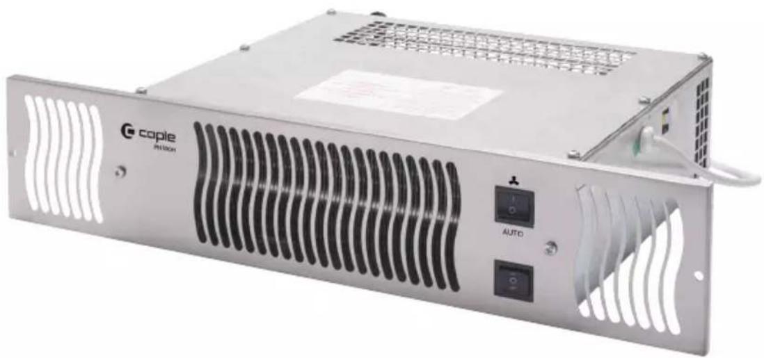
Hydronic Plinth Heater Instruction Manual
PH500H
natural_image
Exterior view of a Cople P500C power supply unit with ventilation grilles and control buttons (no readable text beyond branding)CONTENTS
Safety Instructions 3
Environmental Protection 5
Fitting Instructions 6
Troubleshooting 10
Care and Maintenance 11
Caple Contact Details 12
SAFETY INSTRUCTIONS
Read these instructions carefully and completely before using your plinth heater, keep it in a convenient place for reference when necessary.
WARNINGS
- This appliance can be used by children aged from 8 years and above.
- Persons with reduced physical, sensory or mental capabilities or lack of experience and knowledge must be supervised and given appropriate instruction concerning the use of the appliance in a safe way and understand the hazards involved.
- Children shall not play with the appliance.
- Cleaning and user maintenance should not be carried out by children without supervision.
- Children less than 8 years of age should be kept away unless continuously supervised.
- The appliance and its accessible parts become hot during use. Care should be taken to avoid touching heating elements.
- To prevent fire hazards do not block the ventilation grille.
- Keep all flammable materials away from the appliance.
- It is dangerous to alter or modify the specifications of the appliance in any way.
- This appliance is intended to be used in household and similar applications such as:
Staff kitchen areas in shops, offices and other working environments.
Farm Houses.
By clients in hotels, motels and other residential type environments.
Bed and breakfast type environments.
- Ensure that the supply cord is not wedged during the installation. If the supply cord is damaged, it must be replaced by a Caple service technician or similarly qualified persons in order to prevent a hazard.
- Do not use harsh abrasive cleaners or sharp metal scrapers to clean the grille, as this may damage or scratch the surface.
- Ensure the appliance is switched off before any cleaning or maintenance.
- A Caple approved engineer or highly competent person(s) should be used for other maintenance requirements.
ENVIRONMENTAL PROTECTION
Waste electrical products should not be disposed of with household waste. Please recycle where facilities exist. Check with your Local Authority or retailer for recycling advice. This appliance is marked according to the European Directive on Waste Electrical and Electronic Equipment (WEEE).
By ensuring this product is disposed of correctly, you will help prevent potential negative consequences for the environment and human health, which could otherwise be caused by inappropriate waste handling of this product. The symbol on the product indicates that this product may not be treated as household waste. Instead it shall be handed over to the applicable collection point for the recycling of electrical and electronic equipment. Disposal must be carried out in accordance with local environmental regulations for waste disposal.
For more detailed information about treatment, recovery and recycling of this product, please contact your local council, your household waste disposal service or the retailer where you purchased the product.
CE DECLARATIONS OF CONFORMITY CE
This appliance has been manufactured to the strictest standards and complies with all applicable legislation, Low Voltage Directive (LVD) and Electromagnetic Compatibility (EMC).
UKCA DECLARATIONS OF CONFORMITY UK CA
This appliance has been manufactured to the strictest standards and complies with all applicable legislation.
WARRANTY
Your new appliance is covered by warranty. The warranty card is enclosed - if it is missing, you must provide the following information to your retailer in order to receive a replacement: date of purchase, model and serial number (placed on the inside of the appliance storage drawer).
Registration can also be completed online by visiting www.caple.co.uk.
Ensure you keep your warranty card safe, you may need to show it to Caple Service together with proof of purchase.
If you fail to show your warranty card you will incur all repair charges.
Spare parts are only available from Caple Service and spare parts authorised centres.
FITTING INSTRUCTIONS
The following items should be included in the box:
1 x Heater unit
2 x flexible hose with isolation valves
1 x Stainless steel fascia grille with fixing screw pack
1 x Instruction manual
STEP 1 LOCATION
Select a location in a cavity beneath a kitchen cupboard ensuring the area is clean and level. Care should be taken not to store perishable goods in the cupboard directly above the heater.
NOTE
This plinth heater must not be fitted in a bathroom or other high humidity area.
STEP 2 CENTRAL HEATING WATER SUPPLY
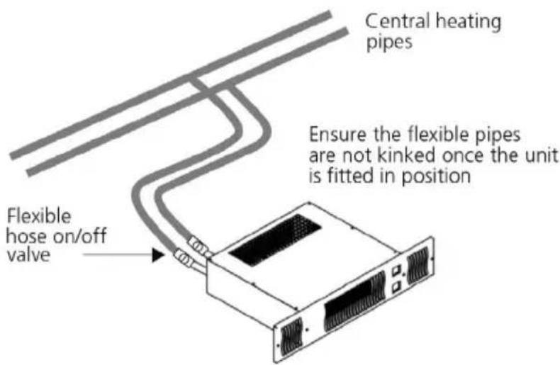
Supply should be through a 2 x 15mm pipe pumped central heating system. The connection points to the central heating pipework should always be to the side of the plinth heater and in a position so when the heater is fully fitted the flexible hoses will not be kinked and the hoses will have as large a radius as possible.
STEP 3 PREPARATION
This product is normally fitted directly onto the floor. Once the position has been decided, mark out and cut the plinth to the dimensions as shown below. Please take care to make the cut out sizes as accurate as possible as the grill is 100m high.
It is recommended that there is a gap of 20mm between the top of the plinth and the shelf of the cupboard above to ensure adequate airflow.
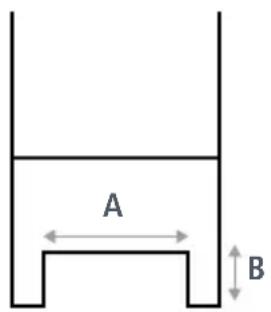
Floor mounting Plinth mounting
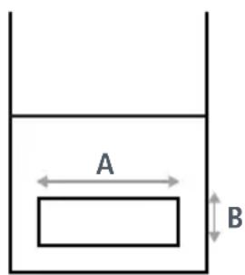
| A | B |
| 360mm | 96mm |
A = Width of cut out
B = Height of cut out
STEP 4 ELECTRICAL SUPPLY
WARNING
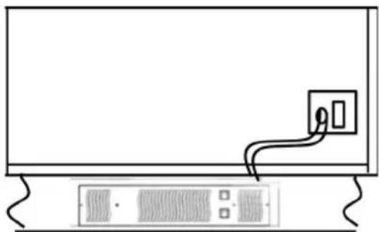
Ensure the power supply to the socket is isolated before starting any work.
Electrical connection should be via a double pole 3 amp fused spur with a minimum contact gap of 3mm. The fused spur should not be directly above the heater unit, but should be accessible after installation. This appliance must be earthed.
natural_image
Simple line drawing of a monitor with an attached power outlet and a separate server rack (no text or symbols)NOTE
It is recommended that all electrical work is carried out by a qualified electrician and Electrical installation must comply with local and national regulations.
STEP 5 WATER CONNECTIONS
Connect the valve end of the flexible hoses to the Plinth Heater, Note the direction of flow arrows on the valves are not important in this application. Always use 2 spanners to tighten the valves to the plinth heater as using only one spanner may damage the copper pipe and block water flow.
Connect the other end of the flexible hoses to the central heating pipework. Note it does not matter which hose is connected to the hot water feed.
Turn on the central heating water supply and the plinth heater isolation valves and check for any leaks. Tighten compression joints if required.
STEP 6 SYSTEM VENTING
Check the water pressure in your heating system is at the correct level, then using the air vent bleed screw at the front top left corner of the heater, loosen the screw and vent any air from the heat exchanger. Use a cloth or sponge to catch any water that may come out of the air vent during this process. Close the vent screw ensuring that there are no leaks.
NOTE
You may need to balance the central heating system if the plinth heater is installed on the same circuit as panel radiators.

STEP 7 FITTING
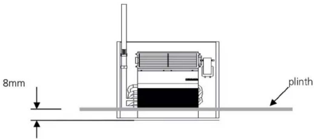
Ensuring that the flexible hoses do not kink and the electrical cable is not in contact with any hot surfaces, slide the plinth heater under the cupboard until the front edge is just behind the line of the plinth.
Replace the plinth and pull the heater through the opening till the front edge projects 8mm through the plinth.
STEP 8 FITTING THE GRILL
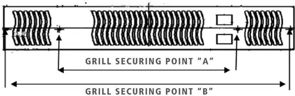
Ensuring the heater is central in the cut out, screw the grill to the front of the plinth heater using the 2 shorter screws at point "A". Then secure the grill to the plinth using the longest screws at point "B".
OPERATION
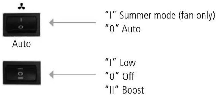
Switch the unit on at the socket. Set the top switch to "0". Select the fan speed to "I" or "II". Turn on your central heating system. The fan will start to rotate provided hot water is circulating through the heat exchanger at or above 43°C. If the central heating system has just been switched on there may be a delay in the fan starting until the central heating hot water reaches 43°C.
When the central heating system switches off, and the system temperature drops below 43^ C, the fan will stop automatically.
During the summer the plinth heater can be used for air circulation without heat. To do this Set the top switch to the position "I". In this position the fan will run until the unit is manually reset.
FAN
FAN DOES NOT RUN ON ANY SWITCH SETTING
Check the power supply is switched ON.
Check fuse in fused spur.
Check the wiring connections at the fused spur.
HEATER DOES NOT SWITCH ON WHEN CENTRAL
Check the top switch is set to "0" and the bottom switch is heating is on is set to "I" or "II".
Check the unit is not air locked. Use bleed valve in front of the unit to release any air.
Balance the central heating system if installed on same circuit as panel radiators and increase the circulating pump speed if required.
Increase the boiler temperature.
CARE AND MAINTENANCE
Before any maintenance is carried out on the unit the electrical supply must be isolated. Maintenance should be restricted to dust and lint removal around the unit. Do not tamper with any electrical parts. A Caple approved engineer should be used for other maintenance requirements.
TECHNICAL DATA
Test Pressure: 10 bar
Maximum working pressure:8 bar
Electrical supply: 220-240 V – 50 Hz.
Water connections: 15mm compression
Heat output: 3057-3979 Btu (0.9 - 1.17kW)
Maximum working pressure: 8bar (1Mpa)
Fuse rating: 3amp

caple
Caple Service
Fourth Way
Avonmouth
Bristol
BS11 8DW
T: 0117 938 1900
E: service@caple.co.uk
www.caple.co.uk
- Hydronic Plinth Heater Instruction Manual
- PH500H
- CONTENTS
- SAFETY INSTRUCTIONS
- WARNINGS
- ENVIRONMENTAL PROTECTION
- CE DECLARATIONS OF CONFORMITY CE
- UKCA DECLARATIONS OF CONFORMITY UK CA
- WARRANTY
- FITTING INSTRUCTIONS
- STEP 1 LOCATION
- NOTE
- STEP 2 CENTRAL HEATING WATER SUPPLY
- STEP 3 PREPARATION
- STEP 4 ELECTRICAL SUPPLY
- WARNING
- STEP 5 WATER CONNECTIONS
- STEP 6 SYSTEM VENTING
- STEP 7 FITTING
- STEP 8 FITTING THE GRILL
- OPERATION
- FAN
- FAN DOES NOT RUN ON ANY SWITCH SETTING
- HEATER DOES NOT SWITCH ON WHEN CENTRAL
- CARE AND MAINTENANCE
- TECHNICAL DATA
- caple
Brand : Caple
Model : PH500H
Category : Heating