
46D9115 - Screen AOC - Free user manual and instructions
Find the device manual for free 46D9115 AOC in PDF.


| Product Type | Public Information Display |
| Brand | AOC |
| Model | 46D9115 |
| Diagonal Screen Size | 116.84 cm (46 inches) |
| Max Resolution | 1920 x 1080 @ 60 Hz |
| Optimum Resolution | 1920 x 1080 @ 60 Hz |
| Viewing Area | 1018.08 mm (H) x 572.67 mm (V) |
| Aspect Ratio | 16:9 |
| Mains Power | 100-240 V~, 50/60 Hz, 3 A |
| Power Consumption (Max) | 170 W |
| Power Consumption (Typical) | 155 W |
| Power Consumption (Standby) | < 0.5 W |
| Dimensions (W x H x D) | 1022.0 x 576.6 x 110.45 mm |
| Operating Temperature | 0 °C to 40 °C |
| Operating Humidity | 20% to 80% RH |
| Operating Altitude | 0 to 3000 m |
| Input Ports | HDMI, DVI, VGA, USB, RS232, IR |
| Remote Control | Included with batteries |
| Wall Mount | VESA compatible (4 M6 screws) |
| Splice Support | Up to 10x10 via RS232/IR loop-through |
| OSD Languages | English, Simplified Chinese |
Frequently Asked Questions - 46D9115 AOC
User questions about 46D9115 AOC
0 question about this device. Answer the ones you know or ask your own.
Ask a new question about this device
Download the instructions for your Screen in PDF format for free! Find your manual 46D9115 - AOC and take your electronic device back in hand. On this page are published all the documents necessary for the use of your device. 46D9115 by AOC.
USER MANUAL 46D9115 AOC
natural_image
Exterior view of a modern flat-screen TV with black screen and diagonal light reflection (no text or symbols visible)Please read this manual before use and retain it for future reference.
Safety Instructions
Safety precautions and maintenance

WARNING: Use of controls, adjustments or procedures other than those specified in this documentation may result in exposure to shock, electrical hazards and/or mechanical hazards.
Read and follow these instructions when connecting and using your display:
Operation:
- Keep the display out of direct sunlight and away from stoves or any other heat sources.
- Remove any object that could fall into ventilation holes or prevent proper cooling of the display's electronics.
- Do not block the ventilation holes on the body of Vibe.
- When positioning the display, make sure the power plug and outlet are easily accessible.
- When turning off the display by detaching the power cord, wait 6 seconds before re-attaching the power cord for normal operation.
- Ensure the use of an approved power cord at all times. If your power cord is missing, please contact your local service center.
- Do not subject the display to strong vibration or high impact during operation.
- Avoid Dropping the display during operation or transportation.
Maintenance:
- To protect your display from possible damage, do not put excessive pressure on the LCD panel. When moving your display, hold the frame to lift; do not lift the display by placing your hand or fingers on the LCD panel.
- Unplug the display if you are not going to use it for an extensive period of time.
- Unplug the display if you need to clean it with a slightly damp cloth. The screen may be wiped with a dry cloth when the power is off. However, never use organic solvent, such as, alcohol, or ammonia-based liquids to clean your display.
- To avoid the risk of shock or permanent damage to the hardware, do not expose the display to dust, rain, water or an excessively moist environment.
- If your display becomes wet, wipe it with dry cloth as soon as possible.
- If a foreign substance or water gets in your display, turn the power off immediately and disconnect the power cord. Then remove the foreign substance or water, and send the unit to the maintenance center.
- Do not store or use the display in locations exposed to heat, direct sunlight or extreme cold.
- In order to maintain the best performance of your display and ensure a longer lifetime, we strongly recommend using the display in a location within the following temperature and humidity ranges.
- Temperature: 0-40°C 32-104°F
- Humidity: 20-80% RH
IMPORTANT: Always activate a moving screen saver program when you leave your display unattended. Always activate a periodic screen refresh application if the unit will display unchanging static content. Uninterrupted display of still or static images over an extended period may cause "burn in", also known as "after-imaging" or "ghost imaging", on your screen. This is a well-known phenomenon in LCD panel technology. In most cases, the "burned in" or "after-imaging" or "ghost imaging" will disappear gradually over a period of time after the power has been switched off.
WARNING: Severe "bum-in" or "after-image" or "ghost image" symptoms will not disappear and cannot be repaired. This is also not covered under the terms of your warranty.
Service:
- The casing cover should be opened only by qualified service personnel.
- If there is any need for repair or integration, please contact your local service center.

If your display does not operate normally, having followed the instructions in this document, please contact a technician or your local service center.
Read and follow these instructions when connecting and using your display:

- Consult a service technician if the display does not operate normally when you have followed the instructions in this manual.
- The back cover should be opened only by qualified service personnel.
- Keep the display out of direct sunlight and away from stoves or any other heat sources.
- Remove any object that could fall into the vents or prevent proper cooling of the display's electronics.
- Do not block the ventilation holes on the cabinet.
- Keep the display dry. To avoid electric shock, do not expose it to rain or excessive moisture.
- When turning off the display by detaching the power cable or DC power cord, wait for 6 seconds before re-attaching the power cable or DC power cord for normal operation.
- To avoid the risk of shock or permanent damage to the set do not expose the display to rain or excessive moisture.
- When positioning the display, make sure the power plug and outlet are easily accessible.
- This product's power cord is equipped with a three-wire grounded plug. The plug only fits in a grounded power outlet. Make sure the power outlet is properly grounded before inserting the power cord plug. Do not insert the plug into a non-grounded power outlet. Contact your electrician for details.
- IMPORTANT: Always activate a screen saver program during your application. If a still image in high contrast remains on the screen for an extended period of time, it may leave an 'after-image' or 'ghost image' on the front of the screen. This is a well-known phenomenon that is caused by the shortcomings inherent in LCD technology. In most cases the afterimage will disappear gradually over a period of time after the power has been switched off. Be aware that the after-image symptom cannot be repaired and is not covered under warranty.
Federal Communications Commission (FCC) Notice (U.S. Only)

This equipment has been tested and found to comply with the limits for a Class A digital device, pursuant to part 15 of the FCC Rules. These limits are designed to provide reasonable protection against harmful interference when the equipment is operated in a commercial environment. This equipment generates, uses and can radiate radio frequency energy and, if not installed and used in accordance with the instruction manual, may cause harmful interference to radio communications. Operation of this equipment in a residential area is likely to cause harmful interference in which case the user will be required to correct the interference at his own expense.

Changes or modifications not expressly approved by the party responsible for compliance could void the user's authority to operate the equipment.
Use only an RF shielded cable that was supplied with the display when connecting this display to a computer device. To prevent damage which may result in fire or shock hazard, do not expose this appliance to rain or excessive moisture.

This device complies with Part 15 of the FCC Rules. Operation is subject to the following two conditions: (1) This device may not cause harmful interference, and (2) this device must accept any interference received, including interference that may cause undesired operation.
End-of-Life Disposal
Your new Public Information Display contains materials that can be recycled and reused. Specialized companies can recycle your product to increase the amount of reusable materials and to minimize the amount to be disposed of.
Please find out about the local regulations on how to dispose of your old display from your local dealer.
(For customers in Canada and U.S.A.)
This product may contain lead and/or mercury. Dispose of in accordance to local-state and federal regulations. For additional information on recycling contact www.eia.org (Consumer Education Initiative)
Waste Electrical and Electronic Equipment-WEEE
Attention users in United States:
Please dispose of according to all Local, State and Federal Laws. For the disposal or recycling information, contact: www.mygreenelectronics.com or www.eiae.org.
End of Life Directives-Recycling

Your new Public Information Display contains several materials that can be recycled for new users. Please dispose of according to all Local, State, and Federal laws.
Table Of Contents
- Unpacking and Installation....1
1.1. Unpacking....
1.2. Package Contents....1
1.3. Installation Notes....1
1.4. Operating Instructions of wall mount brackets....2
- Parts and Functions....4
2.1. Input/Output.....
2.2. Remote Control....5
- Connecting....7
3.1. System connection diagram....7
- Introduction of tiling tool....10
4.1. Example of steps....11
- OSD Menu....12
5.1. Navigating the OSD menu using the remote control.... 12
5.2. OSD Menu Overview....12
-
Input Mode....14
-
Cleaning and Troubleshooting....16
7.1. Cleaning....
7.2. Troubleshooting....17
- Technical Specifications....18
The user interface is subject to change, Please refer to the actual machine for user interactions.
1. Unpacking and Installation
1.1. Unpacking
• This product is packed with the standard accessories.
- Any other optional accessories will be packed separately.
- Due to the size and weight of this display, it is recommended for two people to move it.
• After opening the box, please verify that all parts mentioned below are included and in good condition.
1.2. Package Contents
Please verify that you received the following items with your package:
- LCD display
- Quick Start
• Remote Control and AAA Batteries - Power cord
- HDMI Cable
- RS232 Cable
- RS232+RJ45
- RJ45 Cable
• Wall mount brackets (4pcs) & screws (20pcs) - IR Transducer

NOTES:
- For all other regions, apply a power cord that conforms to the AC voltage of the power outlet that complies with the safety regulations of the particular country.
1.3. Installation Notes
- Due to the high power consumption, always use the plug exclusively designed for this product. If an extended line is required, please consult your service agent.
- The product should be installed on a flat surface to avoid tipping. The distance between the back of the product and the wall should be maintained for proper ventilation. Avoid installing the product in the kitchen, bathroom or any other places with high humidity to avoid shortening the service life of the electronic components.
• The product can normally operate only under 3000m in altitude.
1.4. Operating Instructions of wall mount brackets
1.4.1. Operating Instructions of wall mount brackets
- Clean the table and lay a soft cloth on a table, then beneath the screen surface so as not to scratch the screen face.
- Refer to below graphic, tighten the screws.

flowchart
graph TD
    A["Panel 1"] --> B["Wall mount bracket"]
    B --> C["Panel 2"]
    C --> D["Panel 3"]
    D --> E["Panel 4"]
    E --> F["Panel 5"]
    F --> G["Panel 6"]
    G --> H["Panel 7"]
    H --> I["Panel 8"]
    I --> J["Panel 9"]
    J --> K["Panel 10"]
    style A fill:#f9f,stroke:#333
    style B fill:#ccf,stroke:#333
    style C fill:#cfc,stroke:#333
    style D fill:#fcc,stroke:#333
    style E fill:#cff,stroke:#333
    style F fill:#ffc,stroke:#333
    style G fill:#cfc,stroke:#333
    style H fill:#fcc,stroke:#333
    style I fill:#cfc,stroke:#333
    style J fill:#fcc,stroke:#333
    style K fill:#cfc,stroke:#333
Lock 3 M6 horizontal screws when horizontal hanging.
Lock 3 M6 vertical screws when vertical hanging.
- After tightening the screws, the display can be hung on the wall or spliced on the support.

Mounting in horizontal position Mounting in vertical position
1.4.2. Mounting in Portrait Position
When using the splicing unit for mounting in portrait position, turn the unit clockwise to move the left side to the top. This ensures good ventilation and extends the service life of splicing units.

2 Parts and Functions
2.1. Input/Output

① AC IN
AC power input.
② MAIN POWER SWITCH
Switch the main power on/off.
③ USB PORT
Used for software update function and multimedia play function.
④ RS232 / IR IN / ⑤ RS232 / IR OUT
RS232 / IR network input / output for the loop-through function.
⑥ HDMI IN
HDMI input.
⑦ DVI IN
DVI-D video input.
⑧ VGA IN (D-Sub)
VGA video input.
⑨ IR IN
IR signal input for the loop-through function.
Note:
- This display's remote control sensor will stop working if the jack [IR IN] is connected.
2.2. Remote Control
2.2.1. General functions
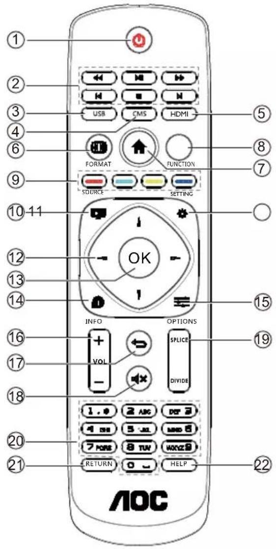
① [POWER button]
Turn the display on or put the display to standby. Long press POWER button until power off.
② [PLAY] buttons
Control playback of media files.
③ [USB] button
Go to USB source.
④ [CMS] button
Go to Cloud CMS app.
⑤ [HDMI] button
Go to HDMI source.
⑥ [FORMAT button]
Reserved.
⑦ [HOME button
Go to Android Launcher first widgets.
⑧ FUNCTION button
Reserved.
⑨ [ ][ ][ ] [ ]COLOR
buttons
Reserved.
⑩ [ ] Source Button
Choose input source.
⑪ [Settings Button
Access the OSD menu.
⑫[ ] [ ] [ ] [ ] NAVIGATION buttons
Up, down, left and right operation key.
⑬ [OK] button
Confirm an entry or selection.
14 [i NFO button
Show Information OSD.
⑮ [→] OPTIONS button
Access currently available options, for Media Input/PDF Player/Cloud CMS.
⑯ [+] [—] VOLUME button
Adjust volume level.

[ ] BACK button
Return to the previous page or exit from the previous function.
![AOC 46D9115 - [ ] BACK button - 1](/content/2026/05/1061612/images/cfe10c9527cde38769368375902ea5f218f9111c99847effc0ff7d58e03b6b56.jpg)
[1] MUTE button
Mute or restore volume.
![AOC 46D9115 - [1] MUTE button - 1](/content/2026/05/1061612/images/46a7bfff98ada34416de19dcff39cb373617baa6187e182ad6fbbe82bea03da2.jpg)
[SPLICE] button
Full screen display function.
Note: After the successful setting of the splice mode, this key can realize one-key integration of the entire splice unit into a screen display.
[DIVIDE] button
Single screen display function.
Note: After the successful setting of the splice mode, this key can realize one key to decompose the synthesized screen display into single screen display.
![AOC 46D9115 - [DIVIDE] button - 1](/content/2026/05/1061612/images/3846740d634df0fdff2c5f5a7761be6a2b663bb6a3a85f2bfdfcb35d61cd3934.jpg)
[Number] button
Input figures or text.
![AOC 46D9115 - [Number] button - 1](/content/2026/05/1061612/images/873a146a9d2efb4a690e1a6cd842c640ba625332039e6d7e4d82bdd0c7988d78.jpg)
[RETURN] button
Reserved.
![AOC 46D9115 - [RETURN] button - 1](/content/2026/05/1061612/images/76df274796ff0bcf21b92a7f01896cbe4edebb61c2882b61db74153392b27605.jpg)
[HELP] Button
Reserved.
3. Connecting
3.1. System connection diagram
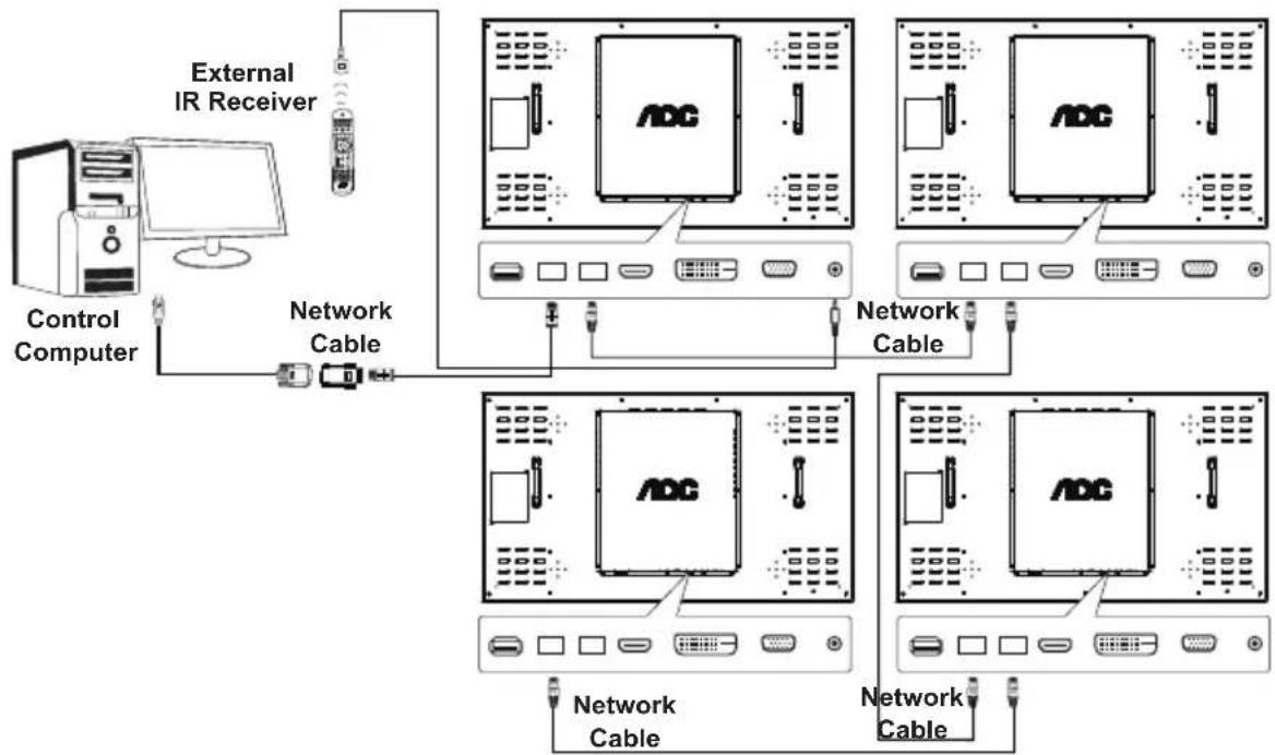
3.1.1. Splice control signal connection
Note: In the following diagram, 2x2 splice is used as an example:
flowchart
graph TD
    A["Control Computer"] --> B["External IR Receiver"]
    B --> C["Network Cable"]
    C --> D["Network Cable"]
    D --> E["ADC 1"]
    D --> F["ADC 2"]
    D --> G["ADC 3"]
    D --> H["ADC 4"]
    D --> I["Network Cable"]
    I --> J["Network Cable"]
    J --> K["Network Cable"]
Instruction:
- Connect the control signal to RS232 IN of the first machine, and connect from RS232 OUT ring to RS232 IN of the next machine.
- If the computer has no serial output, you can use the USB adapter to connect (Cable 1) computer to the splice unit of the first computer and connect to the serial port of machine via USB.
- If you need IR ring connection control, you can use the external IR receiver input. The IR output will make a serial connection with the network cable to the next machine.
- For your convenience, the above RS232 to LAN adapter, USB to COM cable and its driver are recommended to use the original AOC cable and driver.
3.1.2. Splice signal connection
Solution 1: DVI+DVI distributor (maximum supported resolution 3840x2160@30Hz) (The maximum resolution can only be supported when using the HDMI-DVI cable)

flowchart
graph TD
    A["Control Computer"] -->|DVI Cable| B["DVI Matrix"]
    B -->|RS232 Cable| C["Signal Source"]
    C -->|DVI Cable| B
    B -->|DVI Cable| D["DVI Cable"]
    D --> E["Output"]
    style A fill:#f9f,stroke:#333
    style B fill:#ccf,stroke:#333
    style C fill:#cfc,stroke:#333
    style D fill:#fcc,stroke:#333
Solution 2: HDMI+HDMI matrix (maximum supported resolution 3840x2160@60Hz)

flowchart
graph TD
    A["Signal Source"] --> B["HDMI Cable"]
    B --> C["RS232 Cable"]
    C --> D["Control Computer"]
    D --> E["HDMI Matrix (HDMI2.0)"]
    E --> F["HDMI1"]
    F --> G["HDMI2"]
    G --> H["HDMI3"]
    H --> I["HDMI4"]
    I --> J["HDMI1"]
    I --> K["HDMI2"]
    K --> L["HDMI3"]
    K --> M["HDMI4"]
Note: Connect the signal source output to the matrix input. The signal is connected to the HDMI of multiple machines via matrix output. The RS232 serial port of the matrix connects the control computer via RS232 cable.

flowchart
graph TD
    A["Control Computer"] -->|VGA Cable| B["RS232 Cable"]
    B --> C["Signal Source"]
    C --> D["VGA Matrix"]
    D --> E["Internal Control Unit"]
    E --> F["VGA Cable"]
    F --> G["Internal Control Unit"]
    G --> H["VGA Cable"]
    H --> I["Internal Control Unit"]
    I --> J["VGA Cable"]
    J --> K["Internal Control Unit"]
    K --> L["VGA Cable"]
    L --> M["Internal Control Unit"]
    M --> N["VGA Cable"]
    N --> O["Internal Control Unit"]
    O --> P["VGA Cable"]
    P --> Q["Internal Control Unit"]
    Q --> R["VGA Cable"]
    R --> S["Internal Control Unit"]
    S --> T["VGA Cable"]
    T --> U["Internal Control Unit"]
    U --> V["VGA Cable"]
Note: Connect the signal source output to the matrix input. The signal is connected to the VGA of multiple machines via matrix output. The RS232 serial port of the matrix connects the control computer via RS232 cable.
Instruction: The matrix in Solutions 2 and 3 can be a hybrid matrix. In order to maintain a good display effect, it is suggested to use the matrix of famous brands in the market or the one we recommended.
4. Introduction of tiling tool
Instruction:
- The tiling tool is provided by dealers. Please contact the dealer for the software.
- This software has a splice unit for regulation and control, and reserve and transfer of common splice method.
-
The software supports the following operating systems: Windows XP/7/8/10.
-
For instructions in detail, please check "Help?" menu of the software.

4.1. Example of steps
Steps:
-
Create a matrix (column, row, connection direction) based on the actual PD-connection cable.
-
Set the PD and matrix serial port (serial port name and baud rate).
-
Click on serial port connection (the fourth button on the top of the main interface). Note: The button icon changes after the connection is made.
-
Login as administrator.
-
In the management region, select "Auto operation" tab and click the following buttons by order:
a. Display the address code: Click on it and the address code should be displayed on all PDs.
b. Distribute the address code: Click on it and wait a while. PDs will display "Distributed" by order:
c. Bind the address code: Click on it and wait a while. PDs will display "Bound" by order.
- Splice operation:
a. Single serial port scenario: Left-click to select any PD and right-click the PD. Select “Combine All” and click “Click and Execute” button to execute splice operation.
b. Double serial port scenario: Left-click to select multiple PDs and right-click the PD area. Select “Combine Display” and select the signal source of PD (HDMI, VGA, DVI) and the matrix input channel (a.k.a. matrix output port). Click “Click and Execute” button to execute splice operation.
- Division operation:
Left-click the spliced PD area and right-click the PD area. Select "Divide Display". Click "Click and Execute" button to execute division operation.
- Set the PD screen parameters:
Left-click the PD and right-click this PD. Select "Screen Parameter Adjustment" and set PD parameters.
5. OSD Menu
5.1. Navigating the OSD menu using the remote control
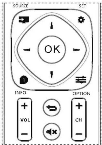
- Press [ ] button on the remote control to display the OSD menu.
- Press [ ] or [ ] button to choose the item you want to adjust.
- Press [OK] or [▶] button to enter the submenu.
- In the submenu, press [ ] or [ ] button to toggle among items, press [ ] or [ ] button to adjust settings. If there is a submenu, press [OK] or [ ] button to enter the submenu.
- Press [ ] button to return to the previous menu, or press [ ] button to exit the OSD menu.
5.2. OSD Menu Overview
5.2.1. IMAGE SETTING

PICTURE MODE
Select picture mode.
CONTRAST
Adjust the image contrast ratio for the input signal.
BRIGHTNESS
Adjust the image brightness for the input signal.
SATURATION
Adjust the saturation of the screen.
Press [▶] button the flesh tone color becomes greenish.
Press [ ] button the flesh tone color becomes purplish.
TINT
Adjust the tint of the screen.
Press [▶] button the tint increase.
Press [ ] button the tint reduce.
NOTE: Video mode only.
SHARPNESS
This function is digitally capable to keep crisp image at any timings.
It is adjustable to get a distinct image or a soft one as you prefer and set independently for each picture mode.
COLOUR TEMP.
It is used to adjust the color temperature.
ASPECT RATIO
Adjust the Wide and high ratio of the screen.
OVERSCAN
Change the display area of the image.
PC SETTING
Adjust VGA screen Settings.
NOTE: Video mode only.
NOISE REDUCTION
Adjust the noise reduction level.
GAMMA
Select a display gamma, It's refer to the brightness performance curve of signal input.
BACKLIGHT
Adjust the image brightness for the background.
5.2.2. TILING

ENABLE
Choose to enable/disable frame function.
H Monitors
Control Horizontal Image position within the display area of the LCD.
V Monitors
Control Vertical Image position within the display area of the LCD.
Position
Select the position of this display in the screen matrix.
Frame Comp.
Choose to turn the frame compensation function on or off.
If selected {Yes}, the display will adjust the image to compensate for the width of the display bezels in order to accurately display the image.
Switch On Delay
Set the power-on delaying function.
5.2.3. SYSTEM
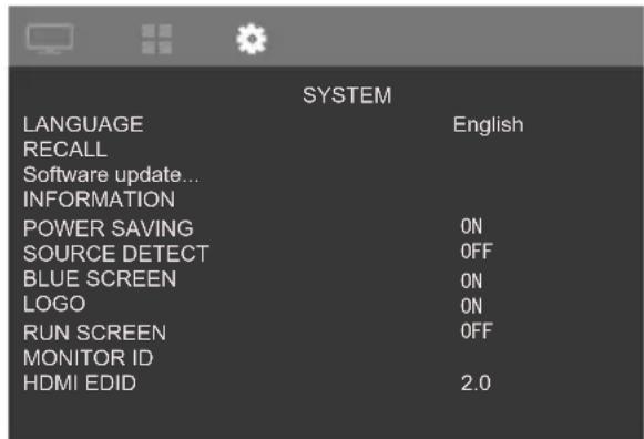
LANGUAGE
Select the language used in the OSD menu.
The options are: English/简体中文
RECALL
Reset all settings to the factory preset values.
Software Update...
Update scalar FW by USB.
INFORMATION
Shows information about your display,
POWER SAVING
Turn on or off the power save modes.
SOURCE DETECT
Choose to let the display detect and display available signal sources automatically.
BLUE SCREEN
Turn on or off blue screen mode.
LOGO
Choose to enable or disable the picture of Logo when turn on your display.
RUN SCREEN
Turn on or off run screen function.
MONITOR ID
Set the ID number for controlling the display via the RS232C connection. Each display must have a unique ID number when multiple sets of this display are connected. Monitor ID number range is between 1 to 255.
HDMI EDID
Choose supported HDMI EDID.
Help
Selection online help.
6. Input Mode
PC Resolution:
| Standard Resolution | Active Resolution | Refresh Rate Pixe | Rate | |
| H Pixels V Lines | ||||
| VGA 640 480 | 60 Hz 25.175 MHz | |||
| 72 Hz 31.5 MHz | ||||
| 75 Hz 31.5 MHz | ||||
| WVGA 720 400 | 70 Hz 28.322 MHz | |||
| SVGA 800 | 600 | 60 Hz 40 MHz | ||
| 75 Hz 49.5 MHz | ||||
| XGA 1024 768 | 60 Hz 65 MHz | |||
| 75 Hz | 78.75 MHz | |||
| WXGA 1280 768 | 60 Hz | 79.5 MHz | ||
| SXGA | 1280 | 1024 | 60 Hz 108 MHz | |
| WXGA 1360 768 | 60 Hz | 85.5 MHz | ||
| UXGA | 1600 | 1200 | 60 Hz 162 MHz | |
| HD1080 | 1920 | 1080 | 60 Hz 148.5 MHz | |
SD Resolution:
| Standard Resolution | Active Resolution | Refresh Rate Pixe | Rate | |
| H Pixels V Lines | ||||
| 480i | 720 480 59.94 Hz | 27 MHz | ||
| 480p | ||||
| 576i | 720 576 50 Hz | 27 MHz | ||
| 576p | ||||
HD Resolution:
| Standard Resolution | Active Resolution | Refresh Rate Pixe | Rate | |
| H Pixels V Lines | ||||
| 720p 1280 720 | 50 Hz | 74.25 MHz | ||
| 60 Hz | ||||
| 1080i | 1920 | 1080 | 50 Hz 74.25 MHz | |
| 60 Hz | 74.176 MHz | |||
| 1080p | 1920 | 1080 | 50 Hz 148.5 MHz | |
| 60 Hz 148.325 MHz | ||||
| 2160i | 3840 | 2160 | 30 Hz 297 MHz | |
| 2160p(only support HDMI) | 3840 | 2160 | 60 Hz 594 MHz | |
- The PC text quality is optimum in HD 1080 mode (1920 x 1080, 60Hz).
- Your PC display screen might appear different depending on the manufacturer (and your particular version of Windows).
- Check your PC instruction book for information about connecting your PC to a display.
- If a vertical and horizontal frequency-select mode exists, select 60Hz (vertical) and 31.5KHz (horizontal). In some cases, abnormal signals (such as stripes) might appear on the screen when the PC power is turned off (or if the PC is disconnected). If so, press the [INPUT] button to enter the video mode. Also, make sure that the PC is connected.
- When horizontal synchronous signals seem irregular in RGB mode, check PC power saving mode or cable connections.
- The display settings table complies to the IBM/VESA standards, and based on the analog input.
- The DVI support mode is regarded as same to the PC support mode.
- The best timing for the vertical frequency to each mode is 60Hz.
7. Cleaning and Troubleshooting
7.1. Cleaning
Caution When Using the Display
- Do not bring your hands, face or objects close to the ventilation holes of the display. The top of the display is usually very hot due to the high temperature of exhaust air being released through the ventilation holes. Burns or personal injuries may occur if any body parts are brought too close. Placing any object near the top of the display could also result in heat related damage to the object as well as the display itself.
- Be sure to disconnect all cables before moving the display. Moving the display with its cables attached may damage the cables and thus cause fire or electric shock.
- Disconnect the power plug from the wall outlet as a safety precaution before carrying out any type of cleaning or maintenance procedure.
Front Panel Cleaning Instructions
- The front of the display has been specially treated. Wipe the surface gently using only a cleaning cloth or a soft, lint-free cloth.
- If the surface becomes dirty, soak a soft, lint-free cloth in a mild detergent solution. Wring the cloth to remove excess liquid. Wipe the surface of the display to remove dirt. Then use a dry cloth of the same type to dry.
- Do not scratch or hit the surface of the panel with fingers or hard objects of any kind.
- Do not use volatile substances such as insert sprays, solvents and thinners.
Back Panel Cleaning Instructions
- If the cabinet becomes dirty, wipe the cabinet with a soft, dry cloth.
- If the cabinet is extremely dirty, soak a lint-free cloth in a mild detergent solution. Wring the cloth to remove as much moisture as possible. Wipe the cabinet. Use another dry cloth to wipe over until the surface is dry.
- Do not allow any water or detergent to come into contact with the surface of the display. If water or moisture gets inside the unit, operating problems, electrical and shock hazards may result.
- Do not scratch or hit the cabinet with fingers or hard objects of any kind.
- Do not use corrosive substances such as insert sprays, solvents and thinners on the cabinet.
- Do not place anything made from rubber or PVC near the cabinet for extended periods of time.
7.2. Troubleshooting
| Symptom Possible Cause Remedy | ||
| No picture is displayed 1. The power cord is disconnected.2. The main power switch on the back of the display is not switched on.3. The selected input has no connection.4. The display is in standby mode. | 1. Plug in the power cord.2. Make sure the power switch is switched on.3. Connect a signal connection to the display. | |
| Color is abnormal The signal cable is not connected properly. | Make sure that the signal cable is attached firmly to the back of the display. | |
| Picture is distorted with abnormal patterns | 1. The signal cable is not connected properly.2. The input signal is beyond the capabilities of the display. | 1. Make sure that the signal cable is attached firmly.2. Check the video signal source to see if it is beyond the range of the display. Please verify its specifications with this display's specification section. |
| Display image doesn't fill up the full size of the screen | 1. The zoom mode is not set correctly.2. Scan Mode may be set incorrectly to underscan.3. If the image exceeds the screen size, Scan Mode may need to be set to Underscan. | Use the Zoom mode or Custom zoom function in the Screen menu to fine tune display geometry and time frequency parameter. |
| Some picture elements do not light up | Some pixels of the display may not turn on. | This display is manufactured using an extremely high level of precision technology: however, sometimes some pixels of the display may not display. This is not a malfunction. |
| After-Images can still be seen on the display after the display is powered off. (Examples of still pictures include logos, video games, computer images, and images displayed in 4:3 normal mode) | A still picture is displayed for an over extended period of time | Do not allow a still image to be displayed for an extended period of time as this can cause a permanent after-image to remain on the display. |
- Technical Specifications
| Model 46D9115 | ||
| Diagonal screen size 116.84 cm | ||
| Max resolution 1920 (H) x 1080 (V) @ 60 Hz | ||
| Optimum resolution 1920 x 1080 @60 Hz | ||
| Viewing area 1018.08mm (H) x 572.67mm (V) | ||
| Mains power 100-240V~, 50-60 Hz 3A | ||
| Power Consumption 170 W(Max) | 155 W(Typical) | |
| Power Consumption (Standby) < 0.5 W | ||
| Dimensions (Without Stand) [W x H x D] | 1022.0 x 576.6 x 110.45 mm | |
| Temperature Operational | 0 | °C - 40°C |
| Storage -20 | °C - 60°C | |
| Humidity | Operational 20% - 80% | |
| Storage | 10% - 90% | |
| Altitude | Operational | 0 - 3,000 m |
| Storage 0 - 9,000 m | ||
| Model 55D9115 | ||
| Diagonal screen size 139.7 cm | ||
| Max resolution 1920 (H) × 1080 (V) @ 60 Hz | ||
| Optimum resolution 1920 × 1080 @60 Hz | ||
| Viewing area 1209.6mm (H) × 680.4mm (V) | ||
| Mains power 100-240V~, 50-60 Hz 3A | ||
| Power Consumption 260 W(Max) | 245 W(Typical) | |
| Power Consumption (Standby) < 0.5 W | ||
| Dimensions (Without Stand) [W × H × D] | 1213.7 × 684.5 × 111.15 mm | |
| Temperature Operational | 0 | °C - 40°C |
| Storage -20 | °C - 60°C | |
| Humidity | Operational 20% - 80% | |
| Storage | 10% - 90% | |
| Altitude | Operational | 0 - 3,000 m |
| Storage 0 - 9,000 m | ||
- Safety Instructions
- Safety precautions and maintenance
- Read and follow these instructions when connecting and using your display:
- Operation:
- Maintenance:
- Service:
- Federal Communications Commission (FCC) Notice (U.S. Only)
- End-of-Life Disposal
- (For customers in Canada and U.S.A.)
- Waste Electrical and Electronic Equipment-WEEE
- Attention users in United States:
- End of Life Directives-Recycling
- Table Of Contents
- Unpacking and Installation
- Unpacking
- Package Contents
- NOTES:
- Installation Notes
- Operating Instructions of wall mount brackets
- Operating Instructions of wall mount brackets
- Mounting in Portrait Position
- Parts and Functions
- Input/Output
- Remote Control
- [ ] BACK button
- [1] MUTE button
- [SPLICE] button
- [DIVIDE] button
- [Number] button
- [RETURN] button
- [HELP] Button
- Connecting
- System connection diagram
- Splice control signal connection
- Instruction:
- Splice signal connection
- Introduction of tiling tool
- Example of steps
- Steps:
- OSD Menu
- Navigating the OSD menu using the remote control
- OSD Menu Overview
- IMAGE SETTING
- PICTURE MODE
- CONTRAST
- BRIGHTNESS
- SATURATION
- TINT
- SHARPNESS
- COLOUR TEMP.
- ASPECT RATIO
- OVERSCAN
- PC SETTING
- NOISE REDUCTION
- GAMMA
- BACKLIGHT
- TILING
- ENABLE
- H Monitors
- V Monitors
- Position
- Frame Comp.
- Switch On Delay
- SYSTEM
- LANGUAGE
- RECALL
- Software Update...
- INFORMATION
- POWER SAVING
- SOURCE DETECT
- BLUE SCREEN
- LOGO
- RUN SCREEN
- MONITOR ID
- HDMI EDID
- Help
- Input Mode
- Cleaning and Troubleshooting
- Cleaning
- Caution When Using the Display
- Front Panel Cleaning Instructions
- Back Panel Cleaning Instructions
Brand : AOC
Model : 46D9115
Category : Screen