
HTD-2526PF - Hedge Trimmer Tanaka - Free user manual and instructions
Find the device manual for free HTD-2526PF Tanaka in PDF.


| Product Type | Hedge Trimmer |
| Brand | Tanaka |
| Model | HTD-2526PF |
| Engine Displacement | 24 ml (1.48 cu in) |
| Fuel Tank Capacity | 0.33 L (11.1 fl oz) |
| Dry Weight | 4.8 kg (10.8 lbs) |
| Overall Cutter Length | 650 mm (25.59 in) |
| Sound Pressure Level (Lp) | 98.3 dB(A) |
| Sound Power Level (Lw) | 104 dB(A) |
| Vibration Level (Front Handle) | 3.9 m/s² |
| Vibration Level (Rear Handle) | 4.8 m/s² |
| Spark Plug | NGK BPM-6A or Champion CJ-8Y |
| Fuel Mix Ratio | 50:1 (gasoline to 2-cycle oil) |
| Starting System | Recoil starter with primer bulb |
| Carburetor Adjustment | Idle speed screw (T) |
| Air Filter Type | Foam element, oiled |
| Spark Plug Gap | 0.6 mm (0.024 in) |
| Gear Case Lubrication Interval | Every 50 hours of use |
| Blade Type | Double-sided cutting blade |
| Safety Features | Safety trigger, hand guard, blade cover |
| Power Source | Gasoline two-stroke engine |
| Country of Origin | Japan |
Frequently Asked Questions - HTD-2526PF Tanaka
User questions about HTD-2526PF Tanaka
0 question about this device. Answer the ones you know or ask your own.
Ask a new question about this device
Download the instructions for your Hedge Trimmer in PDF format for free! Find your manual HTD-2526PF - Tanaka and take your electronic device back in hand. On this page are published all the documents necessary for the use of your device. HTD-2526PF by Tanaka.
USER MANUAL HTD-2526PF Tanaka
natural_image
Orange and black manual hedge shaver with metal blades (no text or symbols visible)THT-2120

natural_image
Orange and black chainsaw with a long-handled chain, shown against a white background (no text or symbols visible)HTD-2530PF
Before using this unit:
- Read the operator's manual carefully.
- Check that the cutting equipment is correctly assembled and adjusted.
- Start the unit and check the carburetor adjustment. See "Maintenance".

WARNING
The engine exhaust from this product contains chemicals known to the State of California to cause cancer, birth defects and other reproductive harm.

natural_image
Simple black-and-white icon of a smiling face wearing sunglasses inside a circle (no text or symbols)Always wear eye, head and ear protectors when using this unit.

Read, understand and follow all warnings and instructions in this manual and on the unit.

natural_image
Two black-and-white icons: one showing a person reading a book, the other showing an open book (no text or symbols)It is important that you read, fully understand and observe the following safety precautions and warnings. Careless or improper use of the unit may cause serious or fatal injury.
- Recoil Starter
- Fuel Tank
- Safety Trigger
- Throttle Trigger
- Front Handle
- Rear Handle
- Spark Plug
- Hand Guard
- Cutting Blade
- Air Cleaner
- Ignition Switch
- Blunt Guard (optional)
- Gear Case
- Choke Lever
- Lock Button
- Blade Cover
- Lock Button
- Priming Pump


2. Warnings and safety instructions.
Operator Safety
• Always wear a safety face shield or goggles.
- Always wear heavy, long pants, boots and gloves. Do not wear loose clothing, jewelry, short pants, sandals or go barefoot. Secure hair so it is above shoulder length.
- Do not operate tool when you are tired, ill or under the influence of alcohol, drugs or medication.
- Never let a child or inexperienced person operate the machine.
- Wear hearing protection.
- Never start or run the engine inside a closed room or building. Breathing exhaust fumes can kill.
- Keep handles free of oil and fuel.
- Keep hands away from cutting equipment.
- Do not grab or hold the unit by the cutting equipment.
- When the unit is turned off, make sure the engine has stopped before the unit is set down.
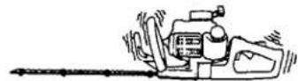
- When operation is prolonged, take a break from time to time so that you may avoid possible white finger disease, which is caused by vibration.
Tool Safety
- Inspect the entire tool before each use. Replace damaged parts. Check for fuel leaks and make sure all fasteners are in place and securely fastened.
- Replace parts that are cracked, chipped or damaged in any way before using the tool.
- Make sure the safety guard is properly attached.
- Keep others away when making carburetor adjustments.
- Use only accessories as recommended for this tools by the manufacturer.
WARNING!
Never modify the tool in any way. Do not use the tool for any job except that for which it is intended.
Fuel Safety
- Mix and pour fuel outdoors and where there are no sparks or flames.
- Use a container approved for fuel.
- Do not smoke or allow smoking near fuel or the tool or while using the tool.
- Wipe up all fuel spills before starting engine.
- Move at least 3 m (10 ft) away from fueling site before starting engine.
- Stop engine before removing fuel cap.
- Empty the fuel tank before storing the tool. It is recommended that the fuel be emptied after each use. If fuel is left in the tank, store so fuel will not leak.
- Store tool and fuel in area where fuel vapors cannot reach sparks or open flames from water heaters, electric motors or switches, furnaces, etc.
WARNING!
Anti-vibration systems do not guarantee that you will not sustain white finger disease or carpal tunnel syndrome. Therefore, continual and regular users should monitor closely the condition of their hands and fingers. If any of the above symptoms appear, seek medical advice immediately.
Cutting Safety
- Do not cut any material other than plant hedge.
- Inspect the area to be cut before each use. Remove objects which can be thrown or become entangled.
- Keep others including children, animals, bystanders and helpers outside the 15 m (50ft) hazard zone. Stop the engine immediately if you are approached.
- Hold the tool firmly with both hands.
- Keep firm footing and balance. Do not over-reach.
- Keep all parts of your body away from the muffler and cutting attachment when the engine is running.
- Keep the cutting tool below shoulder level. NEVER operate unit from a ladder, while in a tree or from any unstable support.
Maintenance Safety
- Maintain the tool according to recommended procedures.
- Disconnect the spark plug before performing maintenance except for carburetor adjustments.
- Keep others away when making carburetor adjustments.
- Use only genuine replacement parts as recommended by the manufacturer.
Transport and storage
- Carry the tool by hand with the engine stopped and the muffler away from your body.
- Allow the engine to cool, empty the fuel tank, and secure the tool before storing or transporting in a vehicle.
- Empty the fuel tank before storing the tool. It is recommended that the fuel be emptied after each use. If fuel is left in the tank, store so fuel will not leak.
- Store tool out of the reach of children.
- Clean the unit carefully and store it in a dry place.
• Make sure engine switch is off when transporting or storing. - When transporting in a vehicle, cover blade with blade cover.
If situations occur which are not covered in this manual, take care and use good judgment. Contact your dealer if you need assistance.
Pay special attention to statements preceded by the following words:
WARNING!
Indicates a strong possibility of severe personal injury or loss of life, if instructions are not followed.
CAUTION!
Indicates a possibility of personal injury or equipment damage, if instructions are not followed.
NOTE!
Helpful information for correct function and use.

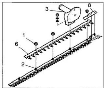

Fig. 1-1
Fig.1-2
Fig. 1-3
3. Assembly procedures
Handle B (3) and Gathering Plate (4) (Fig, 1-1)
- Remove the four washers and nuts (1) from cutting blade end.
NOTE! In case of Handle B installation only, remove only the nut on the longest bolt.
-
Set the gathering plate on the guide bar, then finger tighten the three washers and nuts. *Use one each (5) of the two washers, which have been provided, under the gathering plate or on the two blade-fixing bolts from the cutting-blade end to install the gathering plate on THT-2540. (If so equipped)
-
Set the handle B on the longest bolt and finger tighten with the washer and nut.
-
Before securing the finger-tighten nuts, screw the blade fixing bolts (2) to be seated, then loosen the bolts approx. 1/2 turn.
-
With the bolts set at that position tighten the blade fixing nuts.
Handle B (3) and Blunt guard (6) for USA/ CANADA (Fig. 1-2,3)
- Remove the four nuts (1) (in case of double sided blade, three nuts (1)) from power head side.
NOTE! (For THT-2520, HTD-2530PF)
To set the blunt guard on the unit, loosen the blade fixing bolts so that the blunt guard can be slid into place. Do not use the washer originally used under support plate (8) together with blunt guard.
- Set the blunt guard on the guide bar, then finger tighten the three nuts.
- Set the handle B (3) on the longest bolt (Single sided blade) and finger tighten with the washer and nut.
- Before securing the finger-tighten nuts, screw the blade fixing bolts (2) to be seated, then loosen the bolts approx. 1/2 turn.
- With the bolts set at that position tighten the blade fixing nuts.

Fig.2-1

natural_image
Line drawing of a car air conditioner unit with a dial indicator (no text or symbols)Fig. 2-1B
4. Operating procedures
Fuel (Fig. 2-1)
WARNING!
The hedge trimmer is equipped with a two-stroke engine. Always run the engine on fuel, which is mixed with oil.
Provide good ventilation, when fueling or handling fuel.
Fuel
• Always use branded 89 octane unleaded gasoline.
- Use Tanaka two-cycle oil or a quality two-cycle oil at mixing ratio of 50:1 (Gasoline (A) : Oil (B)).
- Never use multi-grade oil (10 W/30) or waste oil.
• Always mix fuel and oil in a separate clean container.
Always start by filling half the amount of fuel, which is to be used. Then add the whole amount of oil. Mix (shake) the fuel mixture.
Add the remaining amount of fuel.
Mix (shake) the fuel-mix thoroughly before filling the fuel tank.
Fueling

WARNING!
• Always shut off the engine before refueling.
- Slowly open the fuel tank (1), when filling up with fuel, so that possible over-pressure disappears.
- Tighten the fuel cap carefully, after fueling.
• Always move the trimmer at least 3 m (10 ft.) from the fueling area before starting.
Before fueling, clean the tank cap area carefully, to ensure that no dirt falls into the tank.
Make sure that the fuel is well mixed by shaking the container, before fueling.

Fig.2-2

Fig. 2-2B
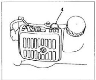
Fig.2-2C
Starting (Fig. 2-2, 2B)
CAUTION!
Before starting, make sure the cutting attachment does not touch anything.
- Set ignition switch (1) to the ON position. (Fig. 2-2)
* Push priming bulb (4) several times so that fuel flows through the bulb or return pipe. (if so equipped)(Fig. 2-2C)
-
With the safety lever (2) pressed (if so equipped), pull throttle trigger and push lock button (3) (if so equipped), then slowly release the throttle trigger first, then the safety lever. This will lock the throttle in the starting position.
-
Set choke lever to CLOSED position (4). (Fig. 2-3)

Fig. 2-3

Fig. 2-3B

natural_image
Line drawing of a person using a power shaver to adjust or install a mechanical component (no text or symbols present)Fig. 2-4

natural_image
Illustration of hands using a tool to adjust or install a mechanical component (no text or symbols visible)Fig. 2-4B
- Pull recoil starter briskly, taking care to keep the handle in your grasp and not allowing it to snap back. (Fig.2-4,4B)
- When you hear the engine want to start, return choke lever to RUN position (open). Then pull recoil starter briskly again.
NOTE!
If engine does not start, repeat procedures from 2 to 5.
6. After starting engine, pull throttle trigger to release throttle lock. Then allow the engine about 2-3 minutes to warm up before subjecting it to any load.

Fig.2-5

Fig.2-5B

natural_image
Mechanical component diagram showing a lever mechanism with no visible text or symbolsFig.2-6
Cutting
When cutting, operate engine at full throttle as this maintains proper cutter speed.
When trimming top of hedge, hold trimmer so blades are between 15 and 30 degrees from a horizontal position and swing trimmer in an arc toward edge of hedge to sweep cuttings off.
When trimming sides of hedge, hold blade vertically and swing unit in an arc.
NOTE! (THT-210/2120/2520, HTD-2526PF/2530PF) (Fig. 2-5)
In case your trimmer is twist handle type (1), please note that the cutting angle can be adjusted by loosening handle locking nut (2). After adjustment has been made, be sure to retighten the nut.
NOTE! (THT-210S) (Fig. 2-5B)
The rear handle can be set in five different positions by pushing the lock button (3) and turning the rear handle. It is extremely important that the handle is locked in the selected position. The lock button can not push while the throttle trigger is pulling.
NOTE: The throttle trigger will not work if the rear handle is unlocked.

natural_image
Line drawing of a mechanical device with no visible text or symbols
natural_image
Technical line drawing of a car interior showing a handle and seat assembly (no text or symbols)Fig.2-6B
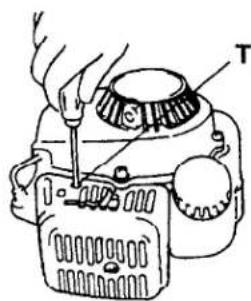
Fig.3-1
Stopping (FIG. 2-6,6B)
Decrease engine speed, and push ignition switch to stop position.
5. Maintenance
MAINTENANCE, REPLACEMENT, OR REPAIR OF THE EMISSION CONTROL DEVICES AND SYSTEMS MAY BE PERFORMED BY ANY NONROAD ENGINE REPAIR ESTABLISHMENT OR INDIVIDUAL.
Carburetor adjustment (Fig. 3-1, 1B)
⚠ WARNING!
The blades may be moving during carburetor adjustments.
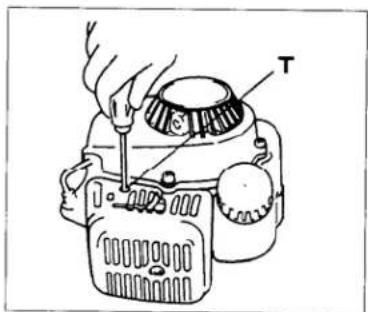
Fig.3-1

Fig.3-1B
WARNING!
Never start the engine without the complete clutch cover! Otherwise the clutch can come loose and cause personal injuries. In the carburetor, fuel is mixed with air. When the engine is test run at the factory, the carburetor is basically adjusted. A further adjustment may be required, according to climate and altitude. The carburetor has one adjustment possibility: T = Idle speed adjustment screw.
Idle speed adjustment (T)
Check that the air filter is clean. When the idle speed is correct, the cutting attachment will not rotate. If adjustment is required, close (clockwise) the T-screw, with the engine running, until the cutting attachment starts to rotate.
Open (counter-clockwise) the screw until the cutting attachment stops. You have reached the correct idle speed when the engine runs smoothly in all positions well below the rpm when the cutting attachment starts to rotate.
If the cutting attachment still rotates after idle speed adjustment, contact your service workshop.
natural_image
Exploded view diagram of a mechanical device showing internal components and assembly (no text or labels)Fig. 3-2

natural_image
Diagram showing three mechanical components with arrows indicating motion, labeled THT-262 (no text or symbols on the diagram itself)Fig. 3-2B
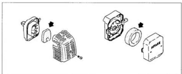
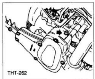
Air filter (Fig. 3-2, 2B)
The air filter must be cleaned from dust and dirt in order to avoid:
• Carburetor malfunctions.
- Starting problems.
• Engine power reduction.
- Unnecessary wear on the engine parts.
• Abnormal fuel consumption.
Clean the air filter daily or more often if working in exceptionally dusty areas.
Cleaning the air filter
Remove the air filter cover and the filter (1).
Rinse it in warm soap suds. Check that the filter is dry before reassembly. An air filter that has been used for some time cannot be cleaned completely. Therefore, it must regularly be replaced with a new one. A damaged filter must always be replaced.
NOTE!
Saturate the element in 2-cycle oil or the equivalent. Squeeze the element to distribute the oil completely and to remove any excess oil.
Spark plug (Fig. 3-3)
The spark plug condition is influenced by:
- An incorrect carburetor setting.
- Wrong fuel mixture (too much oil in the gasoline)
- A dirty air filter.
- Hard running conditions (such as cold weather).
These factors cause deposits on the spark plug electrodes, which may result in malfunction and starting difficulties. If the engine is low on power, difficult to start or runs poorly at idling speed, always check the spark plug first. If the spark plug is dirty, clean it and check the electrode gap. Readjust if necessary. The correct gap is 0.6 mm (.024'). The spark plug should be replaced after about 100 operation hours or earlier if the electrodes are badly eroded.

Fig. 3-3
NOTE!
In some areas, local law requires using a resistor spark plug to suppress ignition signals. If this machine was originally equipped with resistor spark plug, use same type of spark plug for replacement.
Cutter blade (Fig. 3-4, 4B)
The blades are installed to the cutter guide with the four or five bolts. Those bolts are tightened with a clearance so that the cutters can move smoothly.
When clearance is too small:
The cutters do not move properly and the sliding surfaces may seize.
When clearance is too large:
The cutters are poor in sharpness.

natural_image
Illustration of hands using a tool to adjust or install a mechanical component (no text or symbols visible)Fig.3-4

natural_image
Illustration of two hands using a tool to draw a spring, with a small object nearby (no text or symbols)Fig. 3-4B
To adjust the cutter clearance:
- Loosen the cutter fixing nuts.
- Fully tighten the cutter fixing bolts and then loosen them approx. 1/2 turn.
- With the bolts set at that position, tighten the cutter fixing nuts.
Be sure to replace cutter guide fixing bolts when they are loosened, worn or damaged. Also be sure to replace damaged cutter blade.
NOTE!
Properly lubricate the cutter sliding surfaces with machine oil.

natural_image
Line drawing of a manual tool on a vehicle, showing hands operating the blade (no text or symbols)Fig.3-5
natural_image
Technical line drawing of a mechanical assembly with no visible text or symbolsFig. 3-5B

natural_image
Line drawing of a mechanical device emitting smoke or vapor (no text or symbols)Fig. 3-6
Gear case (Fig. 3-5, 5B)
Apply a good quality lithium based grease through the grease fitting until a small amount comes out between the cutter blades and the gear case.
NOTE!
Lubrication should be applied at 50 hour intervals and more frequent at heavy use.
Fuel filter (Fig. 3-6)
Remove the fuel filter from the fuel tank and thoroughly wash it in solvent. After that, push the filter into the tank completely.
NOTE!
If the filter is hard due to dust and dirt, replace it.

Fig.3-7
Cleaning the cylinder fins (Fig. 3-7)
When wood chips are caught between cylinder fins (1), the engine may overheat, resulting in lower output. To avoid this, always keep cylinder fins and fan case clean.
Every 100 Operating hours, or once a year (more often if conditions require), clean fins and external surfaces of engine of dust, dirt and oil deposits which can contribute to improper cooling.
Cleaning the muffler (Fig. 3-8)
Remove the muffler and spark arrestor (if so equipped), and clean out any excess carbon from the exhaust port or muffler inlet every 100 hours of operation.

Fig.3-8
For long-term storage
Drain all fuel from the fuel tank. Start and let engine run until it stops. Repair any damage which has resulted from use. Clean the unit with a clean rag, or the use of high pressure air hose. Put a few drops of two-cycle engine oil into the cylinder through the spark plug hole, and spin the engine over several times to distribute oil. Cover the unit and store it in a dry area.
Maintenance schedule
Below you will find some general maintenance instructions.
For further information please contact your service dealer.
Daily maintenance
- Clean the exterior of the unit.
- Check the blade guard for damage or cracks. Change the guard in case of impacts or cracks.
- Check that the blade is sharp, and without cracks.
- Check that the blade nut is sufficiently tightened.
• Make sure the blade transport guard is undamaged and that it can be securely fitted. - Check that nuts and screws are sufficiently tightened.
Weekly maintenance
- Check the starter, especially cord and return spring.
- Clean the exterior of the spark plug.
- Remove it and check the electrode gap. Adjust it to 0.6 mm, or change the spark plug.
- Clean the cooling fins on the cylinder and make sure the air intake at the starter is not clogged.
- Check that the angle gear is filled with grease.
- Clean the air filter.
Monthly maintenance
- Rinse the fuel tank with gasoline.
- Clean the exterior of the carburetor and the space around it.
-
Clean the fan and the space around it.
-
Specifications
| En | MODEL | THT-210B/S/1800/2120THT-2100/S/2000/L | THT-2520B/S | THT-240B | THT-2510/STHT-2530/2540 |
| Engine Size (ml) | 22 (1.34 cu. in.) | 24 (1.46 cu.in) | 22 (1.34 cu. in.) | 24 (1.46 cu.in) | |
 | |||||
| Spark Plug | NGK BPM-6A or BPMR-6AChampion CJ-8Y or RCJ-8Y | ← | ← | ← | |
 | |||||
| Fuel Tank Capacity (l) | 0.35 (11.8 fl.oz) | 0.35 (11.8 fl.oz) | ← | ← | |
 | |||||
| Dry Weight (kg) | THT-1800 4.1 (9.0 lbs)THT-210B/2120 4.4 (9.7 lbs)THT-2100/S 4.2 (9.2 lbs)THT-210S 4.5 (9.9 lbs)THT-2000 4.0 (8.8 lbs)THT-2000L 4.3 (9.5 lbs) | THT-2520B 4.9 (10.8 lbs)THT-2520S 5.0 (11.0 lbs) | 4.9 (10.8 lbs) | THT-2510/S 5.0 (11.0 lbs)THT-2530 5.2 (11.4 lbs)THT-2540 5.8 (12.3 lbs) | |
 | |||||
| Overall cutter length (mm) | THT-1800 500 (19.69 in)THT-210B/S/2120 650 (25.59 in)THT-2100/S 550 (21.65 in)THT-2000 500 (19.69 in)THT-2000L 620 (24.41 in) | 780 (29.92 in) | 760 (29.92 in) | THT-2510/S 760 (29.92 in)THT-2530 760 (29.92in)THT-2540 1000 (39.37 in) | |
 | |||||
| Blade type | △ | △ | ○ | ○ | |
 | |||||
| Sound pressure level (dB(A)) | LpmeasuredTHT-1800 100.0THT-210B/S/2120 92.1/←/THT-2100/S 93.6THT-2000/L 97.0 | 91.1 | 91.4 | THT-2510/S 93.9/←THT-2530/2540 96.7 / 96.7 | |
 | |||||
| Sound power level (dB(A)) | LwguaranteedTHT-210B/S 104THT-1800 104THT-2120 104THT-2100/S 104THT-2000/L 104 | 104 | 104 | THT-2510/S 104THT-2530/2540 104 | |
 | |||||
| Vibration level (m/s2) | |||||
| Front handle | THT-210B/S/2120 4.2 /4.5/THT-1800 5.1THT-2100/S 4.4/←THT-2000/L 6.8/← | THT-2520B 4.4THT-2520S 7.6 | 3.5 | THT-2510/S 4.7/←THT-2530/2540 7.0/6.8 | |
| Rear handle | THT-210B/S/2120 3.7 /5.2/THT-1800 9.1THT 2100/S 14.2/←THT-2000/L 8.6 | THT-2520B 8.3THT-2520S 6.2 | 5.3 | THT-2510/S 6.4/←THT-2530/2540 7.8/5.8 | |

- Specifications cont.
| En MODEL | HTD-2520PF/2522PFHTD-2526PF/2530PF | HTS-2530PFHTS-2540PF | |
| Engine Size (ml) | 24 (1.48 cu. in.) | ← | |
 | |||
| Spark Plug | NGK BPM-6A or BPMR-6AChampion CJ-8Y or RCJ-8Y | ← | |
 | |||
| Fuel Tank Capacity (l) | 0.33 (11.1 flo7) | ← | |
 | |||
| Dry Weight (kg) | HTD-2520PF 4.4 (9.7 lbs)HTD-2522PF 4.6 (10.1 lbs)HTD-2526PF 4.8 (10.8 lbs)HTD-2530PF 5.3 (11.7 lbs) | HTS-2530PF 5.6 (12.3 lbs)HTS-2540PF 6. ? lbs) | |
 | |||
| Overall cutter length (mm) | HTD-2520PF 550 (21.85 in)HTD-2522PF 550 (21.65 in)HTD-2526PF 650 (25.59 in)HTD-2530PF 760 (27.92 in) | HTS-2530PF 780 (29.92in)HTS-2540PF 1000 (39.37in) | |
 | |||
| Blade type | △ | ○ | |
| :○ | |||
| :△ | |||
| Sound pressure level (dB(A)) ... Lpmeasured | HTD-2520PF 98.3HTD-2526PF 98.3HTD-2526PF 98.3HTD-2530PF 98.3 | HTS-2530PF 98.3HTS-2540PF 98.3 | |
 | |||
| Sound power level (dB(A)) ... Lwguaranteed | HTD-2520PF 104HTD-2522PF 104HTD-2526PF 104HTD-2530PF 104 | HTS-2530PF 104HTS-2540PF 104 | |
 | |||
| Vibration level (m/s2) | |||
| Front handle | HTD-2520PF 4.9HTD-2522PF 4.9HTD-2526PF 3.9HTD-2530PF 4.0HTD-2520PF 7.5HTD-2522PF 7.5HTD-2526PF 4.8HTD-2530PF 6.1 | HTS-2530PF 6.1HTS-2540PF | |
| Rear handle | HTS-2530PF 10.1HTS-2540PF | ||
 | |||
En Declaration of conformity
Fr Déclaration de conformité
® Dichiarazione di conformità
© Konformitätserklärung
Sp Declaración de conformidad
Sw Konformitetsdeklaration
We, Tanaka Kogyo Co., Ltd., 3-4-29 Tsudanuma, Narashino, Chiba. Japan
Nous, soussignés,
Noi,
Der unterzeichnete,
Nosotros,
Vi,
THT-210B/S/240B/1800/2000/L
THT-2100/S/2120/2510/S/2520B/S
THT-2530/2540
HTD-2520PF/2522PF
HTD-2526PF/2530PF
HTS-2530PF/2540PF
Declare under our sole responsibility that the product, hedge Trimmer model
Déclarons sous notre seule responsabilité que le produit en question, tailleuse de haies modèle
Dichiariamo sotto la nostra unica responsabilità che il prodotto, il tosasiepi modello
Erklärt unter, eigener Verantwortung, daß das Produkt, heckenschere modell
Declaramos dajo nuestra única responsabilidad que el producto, cortaseto modelo
Förklarar härmed på eget ansvar att denna produkt, motordriven hacksax modell
to which this declaration relates is in conformity with the essential safety requirements of directives.
89/392/EEC, 91/368/EEC, 93/44/EEC, 93/68/EEC, EMC89/336/EEC, 2000/14/EC
The following standards have been taken into consideration
ISO 3767/3864/10517 (EN 774:1996)
- Before using this unit:
- WARNING
- Warnings and safety instructions.
- Operator Safety
- Tool Safety
- WARNING!
- Fuel Safety
- Cutting Safety
- Maintenance Safety
- Transport and storage
- CAUTION!
- NOTE!
- Assembly procedures
- Handle B (3) and Gathering Plate (4) (Fig, 1-1)
- Handle B (3) and Blunt guard (6) for USA/ CANADA (Fig. 1-2,3)
- NOTE! (For THT-2520, HTD-2530PF)
- Operating procedures
- Fuel (Fig. 2-1)
- Fuel
- Fueling
- Starting (Fig. 2-2, 2B)
- Cutting
- NOTE! (THT-210/2120/2520, HTD-2526PF/2530PF) (Fig. 2-5)
- NOTE! (THT-210S) (Fig. 2-5B)
- Stopping (FIG. 2-6,6B)
- Maintenance
- ⚠ WARNING!
- Idle speed adjustment (T)
- Air filter (Fig. 3-2, 2B)
- Cleaning the air filter
- Spark plug (Fig. 3-3)
- Cutter blade (Fig. 3-4, 4B)
- When clearance is too small:
- When clearance is too large:
- To adjust the cutter clearance:
- Gear case (Fig. 3-5, 5B)
- Fuel filter (Fig. 3-6)
- Cleaning the cylinder fins (Fig. 3-7)
- Cleaning the muffler (Fig. 3-8)
- For long-term storage
- Maintenance schedule
- Daily maintenance
- Weekly maintenance
- Monthly maintenance
Brand : Tanaka
Model : HTD-2526PF
Category : Hedge Trimmer