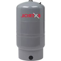
Extrol SX-40V - Water heaters and boilers Amtrol - Free user manual and instructions
Find the device manual for free Extrol SX-40V Amtrol in PDF.


| Product Type | Expansion Tank for Water Heater / Boiler |
| Brand | Amtrol |
| Model | Extrol SX-40V |
| Capacity | 4.0 gallons (15.1 liters) |
| Pre-charge Pressure | 40 psi (2.76 bar) |
| Maximum Working Pressure | 150 psi (10.3 bar) |
| Maximum Temperature | 240°F (115°C) |
| Connection Size | 3/4" NPT female |
| Material | Steel shell with polypropylene liner |
| Diaphragm Material | Butyl rubber |
| Height | 12.5 inches (31.75 cm) |
| Diameter | 12 inches (30.5 cm) |
| Weight | 12 lbs (5.4 kg) |
| Installation | Vertical or horizontal (with bracket) |
| Application | Potable water and hydronic heating systems |
| Maintenance | Check pre-charge pressure annually; drain if waterlogged |
| Warranty | 5 years limited |
| Certifications | ASME, NSF 61-9 |
| Repairability | Replaceable diaphragm; core valve replaceable |
Frequently Asked Questions - Extrol SX-40V Amtrol
User questions about Extrol SX-40V Amtrol
0 question about this device. Answer the ones you know or ask your own.
Ask a new question about this device
Download the instructions for your Water heaters and boilers in PDF format for free! Find your manual Extrol SX-40V - Amtrol and take your electronic device back in hand. On this page are published all the documents necessary for the use of your device. Extrol SX-40V by Amtrol.
USER MANUAL Extrol SX-40V Amtrol
Models EX-15 through EX-90
Models SX-30V through SX-160V
natural_image
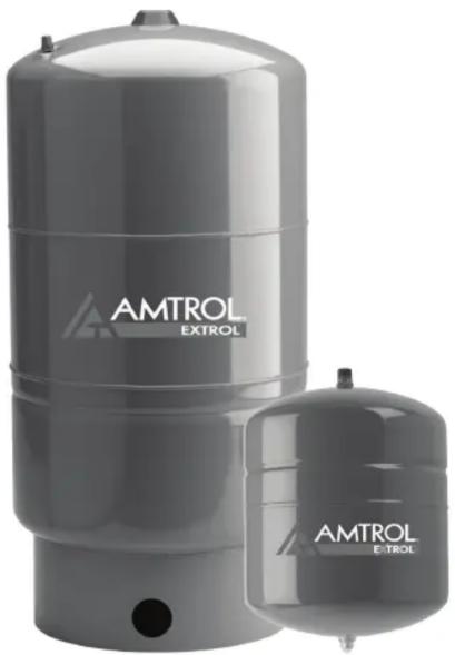
Exterior view of two AMTROL EXTROL water pressure vessels (no signage or text beyond branding)NOTE: Inspect for shipping damage. Notify freight carrier or store where purchased immediately if damage is present. To avoid risk of personal injury and property damage, if the product appears to be malfunctioning or shows signs of corrosion, call a qualified professional immediately. Current copies of the product manual can be viewed at www.amtrol.com. Use proper safety equipment when installing.

THIS IS THE SAFETY ALERT SYMBOL. IT IS USED TO ALERT YOU TO POTENTIAL PERSONAL INJURY AND OTHER HAZARDS. OBEY ALL SAFETY MESSAGES THAT FOLLOW THIS SYMBOL TO REDUCE THE RISK OF PERSONAL INJURY AS WELL AS PROPERTY DAMAGE.
WARNING
USE ONLY IN RESIDENTIAL CLOSED HYDRONIC SYSTEMS. Do not install on domestic
water systems, or in open heating systems. Corrosion and tank failure may result. Use a Therm-X-Trol ^® or Therm-X-Span ^® for domestic water systems. Use a Radiant EXTROL ^® for radiant heating systems where air elimination equipment or barrier tubing is not used.
WARNING
READ CAREFULLY THE PRODUCT
INSTALLATION. OPERATING AND
MAINTENANCE MANUAL. FAILURE TO FOLLOW THE INSTRUCTIONS AND WARNINGS IN THE MANUAL MAY RESULT IN SERIOUS OR FATAL INJURY AND/OR PROPERTY DAMAGE, AND WILL VOID THE PRODUCT WARRANTY. THIS PRODUCT MUST BE INSTALLED BY A LICENSED PROFESSIONAL. FOLLOW ALL APPLICABLE LOCAL AND STATE CODES AND REGULATIONS, IN THE ABSENCE OF SUCH CODES, FOLLOW THE CURRENT EDITIONS OF THE NATIONAL PLUMBING CODE AND NATIONAL ELECTRIC CODE, AS APPLICABLE.
WARNING
This Product, like most Products under pressure, may over time corrode, weaken and burst or
explode, causing serious or fatal injury, leaking or flooding and/or property damage. To minimize risk, a licensed professional must install and periodically inspect and service the Product. A drip pan connected to an adequate drain must be installed if leaking or flooding could cause property damage. Do not locate in an area where leaking could cause property damage to the area adjacent to the appliance or to lower floors of the structure.
WARNING
RUPTURE OR EXPLOSION HAZARD. Do not expose product to freezing temperatures or
temperatures in excess of 240^ F. Do not adjust the pre-charge or re-charge this Product except during installation or regular inspection. Replace the Product and do not adjust the pre-charge if corroded, damaged or with diminished integrity. Adjustments to pre-charge must be done at ambient temperature only. Failure to properly size the Product or follow these instructions may result in excessive strain on the system and may lead to Product failure, serious or fatal personal injury, leakage, and/or property damage.
WARNING
A relief valve must be installed to prevent pressure in excess of local code requirement or maximum
working pressure designated in the Product Manual, whichever is less. At least once every 3 years or if discharge is present, a licensed professional should inspect the pressure relief valve and replace if corrosion is evident or the valve does not function. FAILURE TO INSPECT THIS VALVE AS DIRECTED COULD RESULT IN UNSAFE PRESSURE BUILD-UP WHICH CAN RESULT IN PRODUCT FAILURE, SERIOUS INJURY OR DEATH AND/OR SEVERE PROPERTY DAMAGE AND VOID THE PRODUCT WARRANTY.
WARNING
Chlorine & Aggressive Water: The water quality can significantly influence the life of this Product.
You should test for corrosive elements, acidity, total solids and other relevant contaminants, including chlorine and treat your water appropriately to insure satisfactory performance and prevent premature failure.
WARNING
This product can expose you to chemicals including lead, which is known to the State of California to
cause cancer and birth defects or other reproductive harm. For more information go to www.P65Warnings.ca.gov.
PLEASE READ THE FOLLOWING INSTRUCTIONS CAREFULLY FOR IMPORTANT GENERAL SAFETY INFORMATION AND ADDITIONAL SPECIFIC SAFETY ALERTS. VISIT www.amtrol.com TO VIEW HELPFUL VIDEOS.
Pre-Installation
- Visually inspect for any damage. Ensure expansion tank is sized properly for the application (Figure 1).
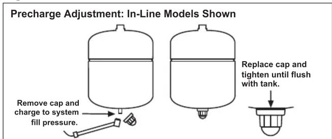
- With tank empty of water, remove plastic cap from air stem (Figure 2).
- Check precharge pressure and adjust if necessary, charging with air to match boiler fill valve setting.
- Replace cap and tighten snugly, ensuring the cap is flush against the tank surface.
Figure 1.
| Boiler Net Output in 1000'S of BTU/Hr. | Type of Radiation | |||
| Finned Tube Baseboard or Radiant Panel | Convectors or Unit Heaters | Radiators Cast Iron | Baseboard Cast Iron | |
| 25 EX-15 | EX-15 EX-15 EX-15 | |||
| 50 EX-15 | EX-15 EX-30 EX-30 | |||
| 75 EX-30 | EX-30 EX-30 EX-60 | |||
| 100 EX-30 | EX-30 EX-60 EX-60 | |||
| 125 EX-30 | EX-60 EX-60 EX-90 | |||
| 150 EX-30 | EX-60 EX-90 EX-90 | |||
| 175 EX-60 | EX-60 SX-30V SX-30V | |||
| 200 EX-60 | EX-90 SX-30V SX-30V | |||
| 250 EX-90 | EX-90 SX-30V SX-40V | |||
| 300 EX-90 | SX-30V SX-40V SX-40V | |||
| 350 SX-30V | SX-30V SX-40V SX-60V | |||
| 400 SX-30V | SX-40V SX-60V SX-60V | |||
| 450 SX-40V | SX-40V SX-60V SX-90V | |||
| 500 SX-40V | SX-40V SX-60V SX-90V | |||
| 550 SX-40V | SX-60V SX-60V SX-90V | |||
| 600 SX-40V | SX-60V SX-90V SX-90V | |||
| 650 SX-60V | SX-60V SX-90V SX-90V | |||
| 700 SX-60V | SX-60V SX-90V SX-90V | |||
| 750 SX-60V | SX-60V SX-90V SX-110V | |||
| 800 SX-60V | SX-90V SX-90V SX-110V | |||
| 850 SX-60V | SX-90V SX-90V SX-110V | |||
| 900 SX-60V | SX-90V SX-110V | SX-110V | ||
| 950 SX-90V | SX-90V SX-110V | SX-110V | ||
| 1,000 | SX-90V SX-90V SX-110V | SX-110V | ||
| 1,100 | SX-90V SX-90V SX-110V | SX-130V | ||
| 1,200 | SX-90V SX-90V SX-110V | SX-130V | ||
| 1,300 | SX-90V SX-110V | SX-130V | SX-160V | |
| 1,400 | SX-110V | SX-130V | SX-160V | SX-160V |
| 1,500 | SX-110V | SX-130V | SX-160V | (2)SX-110V |
Sizing based on: 12 psig Fill; 30 psig Relief Valve; 180°F Average Temperature.
Figure 2.
FAILURE TO PROPERLY SEAL CAP WILL RESULT IN LOSS OF PRECHARGE CAUSING

Mount tank vertically in downward position only. Ensure the piping can support the entire weight of
Models SX-30V through SX-160V are floor standing and may not be hung from the piping.
Do not install the EXTROL on a dead-end pipe or wherever air can collect. This can cause corrosion
and possible leakage.
Installation
- Drain the boiler system or isolate the area where the EXTROL will be installed.
- Install the EXTROL on the supply side of the boiler, on the suction-side of the heating circulator(s) (Figure 3).
- Pressurize the system and check for leaks. Repair as necessary.
- Restart the boiler system and check for relief valve discharge. If the relief valve drips, the tank may be improperly charged or undersized.
Figure 3.

flowchart
graph LR
    A["System Supply"] --> B["Flow-Check Valve"]
    B --> C["Circulator"]
    C --> D["Air Vent"]
    D --> E["Air Purger"]
    E --> F["Fill Valve Assembly"]
    F --> G["Extrrol"]
    G --> H["Inspection Cap"]
    H --> I["Boiler"]
    I --> J["Relief Valve"]
    J --> K["Drain Valve"]
    K --> L["System Return"]
Stand Models: SX-30V through SX-160V

flowchart
graph LR
    A["System Supply"] --> B["Flow-Check Valve"]
    B --> C["Circulator"]
    C --> D["Air Vent"]
    D --> E["Air Separator"]
    E --> F["Boiler"]
    F --> G["Relief Valve"]
    G --> H["Drain Valve"]
    H --> I["System Return"]
    J["Fill Valve Assembly"] --> K["EXTROL"]
    K --> F
Maintenance
A professional plumber should check the complete system, including the expansion tank, yearly and more frequently as the system ages. Checking the precharge allows a small quantity of air to escape and can result in an insufficient air charge. Always check the precharge while the tank is isolated and empty of water, and be sure to maintain the proper precharge whenever the tank is inspected. Monitor the tip of the inspection cap for discoloration (Figure 4) in addition to regular product inspection. Contact the installer or a plumbing professional if inspection cap is discolored; tank replacement required. Do not rely on cap as sole indication of tank condition.
Figure 4.

Warranty
EX Models: Seven (7) Year Limited Warranty
SX Models: One (1) Year Limited Warranty
Visit www.amtrol.com for complete warranty details.

WORTHINGTON
INDUSTRIES
1400 Division Road, West Warwick, RI USA 02893
T: 800.426.8765 www.amtrol.com
© 2021 Worthington Industries Inc.
One or more features of this product are covered by U.S. patents, visit www.amtrol.com/patents for more information.


Part #: 9015-941 (05/21)
Brand : Amtrol
Model : Extrol SX-40V
Category : Water heaters and boilers