
OF16SL - Floor polisher Onfloor Technologies - Free user manual and instructions
Find the device manual for free OF16SL Onfloor Technologies in PDF.

| Product Type | Floor Polisher |
| Brand | Onfloor Technologies |
| Model | OF16SL |
| Power Source | Electric, corded |
| Voltage | 120 V |
| Motor Power | 1.5 HP |
| Operating Width | 16 inches |
| Pad Size | 16 inches diameter |
| Variable Speed | Yes, 0-2000 RPM |
| Weight | Approx. 120 lbs (54 kg) |
| Dimensions (L x W x H) | 26 x 18 x 40 inches |
| Handle | Adjustable ergonomic handle |
| Drive System | Direct drive |
| Safety Features | Safety switch, emergency stop |
| Maintenance | Regular pad cleaning, brush inspection |
| Parts & Repairability | Replaceable pads and brushes |
| Warranty | 1 year limited |
| Certifications | UL listed, CSA certified |
Frequently Asked Questions - OF16SL Onfloor Technologies
User questions about OF16SL Onfloor Technologies
0 question about this device. Answer the ones you know or ask your own.
Ask a new question about this device
Download the instructions for your Floor polisher in PDF format for free! Find your manual OF16SL - Onfloor Technologies and take your electronic device back in hand. On this page are published all the documents necessary for the use of your device. OF16SL by Onfloor Technologies.
USER MANUAL OF16SL Onfloor Technologies
Safety, Operation Manual & Parts List
OF16SH & OF16SL Multi-Purpose Floor Machine
natural_image
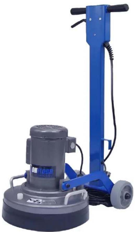
Blue and gray industrial cleaning machine with wheels and a clearer, no visible text or symbolsSAVE THESE INSTRUCTIONS
Address: 777 South Street, Newburgh, New York 12550-0606
TEL: 877.356.6703 / 845.565.6623
Internet Address: www.onfloor.com / info@onfloor.com
Table of Contents
General Instructions .... 3
Silica Vacuum Warning 4
Important Safety Instructions .... 5
Grounding Instructions & Methods....6
Operating Instructions....7
Installation & Changing of Accessory Tools 8
Changing and Installation of Attachments 8
Belt Changing Instructions 9
Inner Bowl Removal Instructions .... 10
Inner Bowl Bearing Replacement 11
Pulley Bearing Replacement 14
General Safety Precautions....17
Machine Maintenance 17
16" Handle & Base Assembly Drawing & Parts List .... 18
16" Outer Bowl Drawing & Parts List 19
16" Inner Bowl Drawing & Parts List .... 20
Troubleshooting Guide 21
Warranty Information....22
General Instructions
READ & FOLLOW ALL INSTRUCTIONS BEFORE USING THIS FLOOR MACHINE
This floor machine will afford you many years of trouble free operating satisfaction if it is given proper care. All parts have passed rigid quality control standards before being assembled to produce the finished product. Prior to packaging, units are again inspected for assurance of flawless operation.
This floor machine was protectively packed to prevent damage in shipment. We recommend that upon delivery, remove the unit from its carton and carefully inspect it for any possible damage in transit. A warranty card is affixed to the handle. It is your responsibility to fill it out and send it to our office to register your purchase and start your warranty. Failure to send us this card in one week upon receipt of the machine may void the warranty.
If damage is discovered, immediately notify the transportation company that delivered your floor machine. As a shipper, we are unable to act upon any claim for concealed damage. You must originate any claim within 5 days of delivery.
These instructions are for your protection and information. PLEASE READ CAREFULLY! Failure to follow these precautions could result in injury or discomfort.
Treat this floor machine as you would any other high-grade precision-made product. Throwing, dropping, unreasonable bumping across thresholds and other misuse may result in a damaged unit and invalidate the warranty.
[This section intentionally left blank]
Silica Vacuum Warning

- Grinding/sanding of masonry, concrete, metal and other materials with silica in composition may give off dust or mists containing crystalline silica.
Silica is a basic component of sand, quartz, brick clay, granite and numerous other minerals and rocks. Repeated and/or substantial inhalation of airborne crystalline silica can cause serious or fatal respiratory diseases, including silicosis. In addition, California and some other authorities have listed respirable crystalline silica as a substance known to cause cancer. When grinding such materials, always follow respiratory precautions. Use appropriate NIOSH-approved respiratory protection and OSHA approved vacuum where dust hazard may occur.
CALIFORNIA PROPOSITION 65 MESSAGE Some dust created by power sanding, sawing, grinding, drilling, and other construction activities contain chemicals known (to the State of California) to cause cancer, birth defects or other reproductive harm. Some examples of these chemicals are: • Lead, from lead-based paints • Crystalline silica from bricks, cement and other masonry products • Arsenic and chromium, from chemically treated lumber. For further information, consult the following sources:
http://www.osha.gov/dsg/topics/silicacrystalline/index.html
http://www.cdc.gov/niosh/docs/96-112/
http://oehha.ca.gov/prop65/law/P65law72003.html
http://www.dir.ca.gov/Title8/sub4.html
Your risk from these exposures varies depending on how often you do this type of work. To reduce your exposure to these chemicals, work in a well-ventilated area, and work with approved safety equipment, such as dust masks that are specially designed to filter out microscopic particles. The use of a dust extraction device should always be used when grinding/sanding dry with Onfloor equipment. To achieve a high level of dust collection, use an industrial HEPA vacuum cleaner.
Important Safety Instructions

To reduce the risk of fire, electric shock or injury: Read all instructions before using this floor machine.
1) DO NOT leave the floor machine plugged in when not in use. Unplug from the outlet when not in use and/or before servicing.
2) Electric shock could occur if exposed to rain. Store indoors.
3) This is NOT a toy. Close attention is necessary when used around or near children.
4) Use only as described in this manual. Use only manufacturer's recommended attachments.
5) DO NOT use with damaged cord plug. If the floor machine is not working as it should because it has been dropped, damaged, left outdoors, or dropped into water, contact the manufacturer or authorized service center.
6) DO NOT handle the plug or operate with wet hands.
7) DO NOT pull or carry by cord, use power cord as a handle, close a door on cord, or pull cord around sharp edges or corners. DO NOT run floor machine over the cord. Keep cord away from heated surfaces.
8) DO NOT unplug by pulling on cord. To un- plug, grasp plug, not the power cord.
9) DO NOT put any object into motor openings.
10) Keep hair, loose clothing, fingers and all parts of body away from moving parts.
11) DO NOT use a vacuum without the proper manufacturer's filters in place.
12) DO NOT operate where anesthetics and oxygen are used.
13) DO NOT use around flammable or combustible liquids such as gasoline or use in areas where they may be present.
14) Replace damaged or worn parts immediately with genuine Onfloor equipment parts to maintain safety and protect your limited warranty.
15) Floor sanding can result in an explosive mixture of fine dust and air. Use a floor sanding machine only in a well-ventilated area.
16) This floor machine must be connected to a properly grounded outlet only. (See grounding method on page 6)
Grounding Instructions & Methods

Improper use of the grounding plug can result in a risk of electric shock!
This floor machine must be grounded. Grounding provides a path of least resistance for electrical current to reduce the risk of electric shock.
This machine is equipped with an equipment-grounded plug. The plug must be inserted into an appropriate outlet that is properly installed and grounded in accordance with all local codes and ordinances.
If repair or replacement of the cord or plug is necessary, DO NOT connect the grounding wire to either flat blade terminal. The insulated wire with an outer surface that is green with or with-out yellow stripes is the grounding wire.
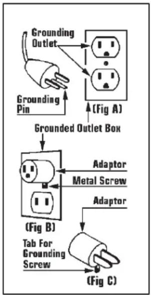
The floor machine is for use on a nominal 120 volt circuit and has a grounding plug that looks like the plug illustrated in (Fig A). A temporary adaptor that looks like the adaptor illustrated in (Fig B & C) may be used to connect the plug to a 2-pole receptacle as shown in (Fig A) if a properly grounded outlet is not available.
The temporary adaptor should be used only until a properly grounded outlet (Fig A) can be installed by a qualified electrician. The green color rigid ear, lug, or like extending from the adaptor must be connected to a permanent ground such as a properly grounded outlet box cover. Whenever the adaptor is used, it must be held in place by the metal screw (Fig C).

WARNING: Improper connection of the equipment-grounding conductor can result in a risk of electrical shock. Check with a qualified electrician or service person if you are in doubt as to whether the outlet is properly grounded. DO NOT modify the plug provided with the machine. If it will not fit the outlet, have a proper outlet installed by a qualified electrician.
NOTE: In Canada, use of a temporary adaptor is not permitted by the Canadian Electrical Code.
flowchart
graph TD
    A["Grounding Pin"] --> B["Grounding Outlet"]
    B --> C["(Fig A)"]
    C --> D["Grounded Outlet Box"]
    D --> E["(Fig B)"]
    E --> F["Adaptor Metal Screw"]
    E --> G["Adaptor"]
    G --> H["(Fig C)"]
    H --> I["Tab For Grounding Screw"]
Operating Instructions
1) Clear the floor of any materials or objects.
2) Select and install the accessory tools required for the job. (See p 8 for installation instructions.)
3) Move the handle from the upright "storage" position to the angled "operating" position and lock in place with the quick release pin.
4) Place your hands on the handle grips and apply slight pressure to lighten the load on the tools. DO NOT lift the tools off of the ground!
5) Push the start switch toggle forward to "ON" position. Motor will start.
6) When the machine is running, remove handle pressure and lower completely onto the working surface.
7) To stop the machine push, start switch toggle backward to "OFF" position.
Note: If machine unexpectedly shuts down due to a circuit overload, check to see if the on-board circuit breaker has opened. This is located on the handle beneath the handle grips. If the button is extended out, wait 1 minute before pushing in to reset. If the breaker will not reset, wait several minutes before attempting to reset again. If on-board breaker has not opened, check breaker box feeding the outlet that the machine is plugged into. TURN MACHINE TOGGLE TO "OFF" POSITION BEFORE RESETTING CIRCUIT BREAKER.

DO NOT attempt to operate this unit if the machine is not fully assembled. When servicing or replacing accessories turn OFF the machine and disconnect from the power source.
[This section intentionally left blank]
Installation & Changing of Accessory Tools

When installing or changing tools, turn OFF the Machine and disconnect the power cord from the electrical outlet
Before Installation or Changing Attachments:
- Unplug the machine from the wall outlet.
- Ensure handle is in the storage position (straight up) and locked in place with the quick release pin.
- Tilt machine back by bracing it with your foot until the handle is lying on the floor and the three heads are fully exposed. Note: It is recommended that a towel or pad is placed under the machine to protect the floor.
Changing and Installation of Attachments
Always wear protective gloves when installing or removing attachments,
- Position the first attachment head at 12 o'clock.
- Using one hand as leverage and the other to reach beneath the bottom side of the attachment and pull up towards yourself to free it from the mounting pins. Turn the attachment 180 degrees and pull up again and the attachment will be freed.
- Select the attachment required for the job, line up the holes on the attachment with the four metal pins protruding from each of the three heads.
- Push attachments on by hand and if necessary, carefully tap it into place with a rubber mallet.
- Repeat steps 1 thru 4 with the remaining 2 attachments.
- Carefully raise the handle, supporting the axle with your foot to control the head of the machine as it is placed on the floor.
- Since the attachments are different heights, you may need to adjust the dust skirt to make sure it is level with the attachments. This will ensure clean and virtually dust-free operation.
- To adjust skirt, align the skirt with the center of the machine and wrap it around allowing bottom edge of skirt to contact floor.
- Move the handle back to the operating position and lock in place with the quick release pin.
Belt Changing Instructions
1) Unplug the machine from power source.
2) Place handle in the straight up position and lock in place using the quick release pin.
3) Using handle, tilt the machine back until handle is resting on the floor.
4) Remove tools from machine.
5) Remove (9) 1/4 -20 hex bolts and lock washers from the perimeter of cover plate. Remove plate from machine.
6) Vacuum dust and debris from inner bowl.
7) If only the lower belt needs replacing, follow steps below. However, if center or top belt needs replacing, it will be necessary to remove any belts beneath it in order to remove the failed belt.
8) On some older machines, retaining plates were not used on the face of driven pulleys. If your machine is configured this way go to step 11.
9) On machines with old style retaining plates, each driven pulley has (3) Allen socket screws holding the retainer plates in place. Remove these (9) screws and (3) retaining plates then go to step 11.
10) On machines with newer retaining plate design, only remove the single 1/4-20 hex bolt from each of the driven pulleys. Then rotate the retaining plate slightly until keyhole openings in plate allow removal. If plate will not rotate, loosen button head screws slightly and rotate plate. There is no need to remove the button head screws.
11) With the retaining plates removed, and using gloves, pull the belt away from large pulley using a flat screwdriver while slowly rotating pulley. Be careful not to pinch fingers between belt and pulley. Repeat until belt is off driven pulley.
12) To install new belt(s) start with the belt closest to the motor. Wrap belt around center driving pulley first. Then start the belt around the large driven pulley as far as possible. Then using gloves and grabbing the center of the pulley hub, force the pulley to rotate. Belt should seat itself onto teeth of pulley. Repeat steps on other pulleys as required.
13) Reinstall retainer plates if equipped.
14) Replace cover plate and hardware.
15) Replace tools and using handle tilt machine back to upright position.
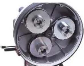
natural_image
Close-up of a mechanical component with three metallic gears and a central hub (no visible text or symbols)Inner Bowl Removal Instructions
This procedure requires a set of retaining ring plyers and safety glasses to complete. If you do not have retaining ring plyers they can be purchased at Lowes, Home Depot, Harbor Freight and other tool stores for about \$20.
1) Unplug machine from power source.
2) Place handle in straight up position and lock in place using the quick release pin.
3) Using the handle, tilt machine sideways until handle is resting on the floor to one side.
4) Remove tools from machine.
5) Remove the (9) ¼-20 hex bolts and lock washers from the perimeter of the cover plate. Remove plate from machine.
6) Vacuum dust and debris from inner bowl.
7) Locate bolt in center of center driving pulley. While holding one of the large driven pulleys to prevent rotation, remove this center bolt and its flat washer. On some machines this removal requires a hex (Allen) wrench while later machines require a 7/16 wrench or socket.
8) On some older machines, retaining plates were not used on the face of the driven pulleys. If your machine is configured this way go to step 11.
9) On machines with old style plates, each driven pulley has (3) Allen socket screws holding the retainer plates in place. Remove these (9) screws and (3) retaining plates then go to step 11.
10) On machines with newer retaining plate design, only remove the single 14 -20 hex bolt from each of the driven pulleys. Then rotate the retaining plate slightly until keyhole openings in plate allow removal. If plate will not rotate, loosen button head screws slightly and rotate plate. There is no need to remove button head screws.
11) With retaining plates removed and using gloves, pull the belt away from large pulley using a flat screwdriver while slowly rotating the pulley. Be careful not to pinch fingers between belt and pulley. Repeat until belt is off pulley. Repeat this process until all three belts have been removed.
12) Remove center driving pulley from motor shaft. This may require prying behind pulley(s) with a large flat screwdriver or a small pry bar. In some extreme cases it may even require the use of a pulley puller tool. Also remove square key.
13) With center pulley removed, locate retaining ring at center of bowl (just behind where center pulley was before removal). Wear safety glasses. Using a pair of retaining ring plyers, remove this retaining ring.
14) Using a clean cloth, wipe away any dust or dirt from the groove where retaining ring was located.
15) Using two of the large pulleys as handles, pull away from machine. This should allow entire inner bowl with large pulleys intact to slide out of machine. If bowl will not slide out try lifting up on pulleys at the same time while pulling away from machine. In rare instances it may require renting a Harmonic Balancer Removal tool from an auto parts store to extract the bowl. If this type of difficulty is experienced contact factory for further guidance.
Inner Bowl Bearing Replacement
With the bowl removed, upper bowl bearings can be serviced.
This job requires a set of retaining ring plyers, safety glasses and the proper replacement bearings. The bearings used here are 6009 bearings with double seals. These are available from Onfloor, part number 245666. It is very important to wear the safety glasses especially when removing and installing the retaining rings. If you do not have retaining ring plyers they can be purchased at Lowes, Home Depot, Harbor Freight, and other tool stores for about \$20.
The steps to remove the inner bowl are covered on page 10 so we will address what to do after removal is accomplished.
When replacing the bearings in the top of the Inner Bowl there are some things that should be pointed out to insure longer life and better performance. The first has to do with the method used to remove and install the new bearing. Remove the retaining ring and proceed to the steps below.
Installation Using a Press
The best method to remove and install new bearings is to take the inner bowl assembly to a hydraulic press and press the bearings in and out. When using this method, it is important to properly support the cast aluminum bowl so as to prevent cracking the casting. This is accomplished by supporting the casting as close as possible to the center while allowing room for the bearings to exit. See illustration A. When pressing the old bearings out it is acceptable to use almost any device as a pushing tool as long as it will fit through the center opening without touching the casting. This means a piece of metal tubing or rod or even a piece of wood that will fit through a 2-11/16" diameter hole. We do not need to be cautious about damaging the old bearings to remove.
When installing the new bearings, first clean the surface of the opening where the bearings are to enter. Support the casting properly (See illustration A on page 12). Use a pusher device that will contact the OUTER RACE. It is important that you do NOT press on the inner race to install the bearings. This will damage the bearings and shorten their life. The best choice for a pushing tool is a round rod/pipe or piece of wood that is just under 3" diameter that will pass through the 2.95" opening in the casting. Many people find a large socket that makes contact with the outer race but fits through the opening. The first bearing must be pressed all the way down to the bottom of the cavity, followed by the spacer ring (you don't want to forget this) then, finally the last bearing. When properly installed the last bearing will be below the retaining ring groove and the retaining ring should go in easily.
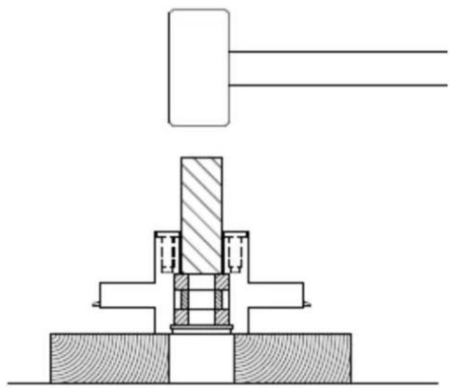
Installation without a Press
When using this method, use a short piece of wood and a mallet/hammer to drive the old bearings from the cast inner bowl. I suggest wood to prevent causing damage to the casting during this step. Support the casting on 2 blocks of 2 x 4 or 4 x 4 lumber (see illustration on page 12). We don't have to be cautious about damaging the old bearings. When installing the new bearings, first clean the surface of the opening where the bearings are to enter. Turn the bowl over and rest its center on a short block of 4 x 4 lumber. (See illustration A on page 12). Place the first bearing in the center opening and place a flat piece of wood or steel across the top of the bearing. It is important that you drive the bearing in straight AND that you do this by applying force to the outer race. It is OK that the flat steel or wood is contacting the inner race as long as the outer race is also in contact. Tap the wood/steel plate with the hammer and slowly drive the bearing until it is flush with the top of the casting. Now there are 2 ways to
proceed. One is to find a round object (large socket, steel tube, steel rod, etc.) that will contact the outer race and also fit through the opening in the casting and use this object to further tap the bearing to the bottom of the cavity. The other way is to use a short wooden dowel 12 or 34 " in diameter and to tap the outer race with small taps as you work the dowel around the perimeter of the outer race as you gradually drive the bearing down to the bottom. When the first bearing is installed, follow with the spacer ring (you don't want to forget this) then; repeat the same process with the top bearing. Then install the retaining ring.
An Important Detail
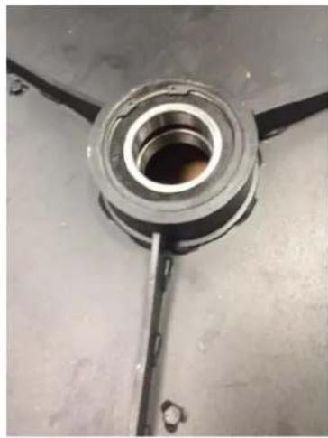
After the bearings and retaining ring has been installed but before the bowl is installed, it is very important that you cover the top of the upper bearing with grease. It makes no difference what the quality of the grease is because it is not being used for lubrication it is serving as a barrier to prevent air born concrete dust from reaching the top bearing. We suggest using grade 3 wheel bearing grease with a putty knife and fill the entire cavity (about 3/16" deep) that exists above the top bearing. This will prevent dust infiltration which is the main cause of this bearing's failure. The attached Photo shows the top bearing before and after grease has been applied.
natural_image
Close-up of a mechanical component with a central bore and three arms, mounted on a plain surface (no visible text or symbols)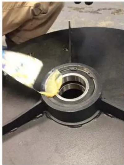
natural_image
Close-up of a mechanical component with a yellow tool applying material to a circular opening (no visible text or symbols)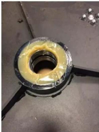
natural_image
Close-up of a damaged mechanical component with yellow coating and central hole, mounted on a metal frame (no visible text or symbols)
REMOVING OLD BEARINGS
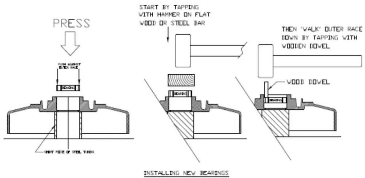
ILLUSTRATION A
Pulley Bearing Replacement
This job requires a set of retaining ring plyers, safety glasses and the proper replacement bearings as well as some general hand tools. The bearings used here are 6203 bearings with double seals. These are available from Onfloor, part number 245321. It is very important to wear the safety glasses especially when removing and installing the retaining rings. If you do not have retaining ring plyers they can be purchased at Lowes, Home Depot, Harbor Freight, and other tool stores for about \$20.
Once the bearings are determined to be in need of replacement, follow the steps below to remove the pulley(s) that need replacement bearings:
- With the handle in the straight up position, tilt the machine to its side so the machine is resting on the side of the outer bowl and one of the handle grips. This makes the machine stable and less likely to tip over.
- Remove the tools.
- Remove the 9 fasteners around the perimeter of the dust cover. On some machines these were Philips head screws. On later machines these are 14 -20 hex head bolts requiring a 7/16 socket and ratchet or a 7/16 wrench. Remove dust cover.
- Remove belt keeper plates on the face of each pulley. To do this you will need to remove the 3 small screws on older machines. On later model machines it is only necessary to remove the single hex head bolt on each pulley. Then rotate the keeper plate a few degrees until the keyhole openings in the plate align with the remaining screw heads and lift the plate off. An upgrade kit is available to change to this new keeper plate system. For all 16" machines built since 2007 and for 20" machines built prior to the heavy-duty belt system the part number for the upgrade kit is 603775. For 20" machines with heavy duty belt systems the kit number is 603783. There are some much older machines built before 2007 that have pulleys without holes that the kits will not work on.
- Wear gloves to work the belt off the pulley teeth while slowly rotating pulley. Belt will come off the large pulley. Be careful not to pinch your fingers.
- To remove pulley, use a deep well 15/16 socket wrench to remove the locking hex nut located down inside the pulley center opening. The flat washer located behind the nut is a 16mm flat washer and not a standard SAE type so be careful not to lose them as they may be challenging to purchase locally. Pull the pulley straight out and away from the machine. There is also a small spacer located behind the pulley. Be careful not to lose this as well.
With the pulley removed we can proceed with bearing replacement. Look at the pulley from the back and you will see the retaining ring that secures the bearings in place. Wearing your safety glasses and using the retaining ring plyers remove the retaining ring.
Installation Using a Press
The best method to remove and install new bearings is to take the pulley to a hydraulic press and press the bearings in and out. When using this method, it is important to properly support the pulley to allow space for the old bearings to exit. This is accomplished by supporting the pulley as close to the center as practical using 2 pieces of 2 x 4 lumber or 2 pieces of equal thickness steel. When pressing the old bearings out it is acceptable to use almost any device as a pushing tool as long as it will fit through the center opening without touching the pulley. This means a piece of metal tubing or rod or even a piece of
wood that will fit through a 1.29" diameter hole. The same 15/16 socket used to remove the nuts works well for this. We do not need to be cautious about damaging the old bearings to remove. (see illustration page 16)
When installing the new bearings, first clean the surface of the opening where the bearings are to enter. If your pulley has the 4 drive pins installed, I suggest removing them for this process. You will need a 7/16 deep well socket for this. Stand the pulley in the press resting on its front face. Use a pusher device that will contact the OUTER RACE. It is important that you do NOT press on the inner race to install the bearings. This will damage the bearings and shorten their life. The best choice for a pushing tool is a round rod/pipe or piece of wood that is 1-1/2" diameter that will pass through the 1.57" opening in the pulley. (see illustration on page 16) Many people use a large socket that makes contact with the outer race but fits through the opening. The first bearing must be pressed all the way down to the bottom of the cavity, followed by the spacer ring (you don't want to forget this) then, finally the last bearing. Be careful not to over press especially if you left the drive pins in the pulley. When properly installed the last bearing will be below the retaining ring groove and the retaining ring should go in easily.
Installation without a Press
When using this method, use a short piece of wood (or 15/16 socket) and a mallet/hammer to drive the old bearings from the cast inner bowl. Support the pulley on a piece of wood to prevent damaging it. We don't have to be cautious about damaging the old bearings. When installing the new bearings, first clean the surface of the opening where the bearings are to enter. Turn the pulley over and rest its front face (or drive pins if present) on the piece of wood. Place the first bearing in the center opening and place a flat piece of wood or steel across the top of the bearing. It is important that you drive the bearing in straight AND that you do this by applying force to the outer race. It is OK that the flat steel or wood is contacting the inner race as long as the outer race is also in contact. Tap the wood/steel plate with the hammer and slowly drive the bearing until it is flush with the top of the pulley. Now there are 2 ways to proceed. One is to find a round object (large socket, steel tube, steel rod, etc.) that will contact the outer race and also fit through the opening in the pulley and use this object to further tap the bearing to the bottom of the cavity. The other way is to use a short wooden dowel 12 or 34 " in diameter and to tap the outer race with small taps as you work the dowel around the perimeter of the outer race as you gradually drive the bearing down to the bottom. When the first bearing is installed, follow with the spacer ring (you don't want to forget this) then; repeat the same process with the top bearing. Then install the retaining ring.
Reinstall drive pins, pulley, belts, keeper plates, dust cover in reverse order of removal.
natural_image
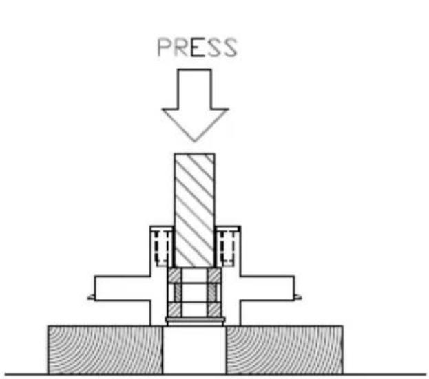
Technical diagram of a mechanical assembly with no visible text or symbolsREMOVING OLD BEARINGS

INSTALLING NEW BEARINGS
General Safety Precautions

This machine is designed for surfacing concrete and sanding wood floors. All operators and maintenance personnel should read and understand the safety procedures with this floor machine.
1) All personnel in the immediate work area must wear safety glasses with side shields whenever the machine is in operation. Protective clothing is also recommended. Long sleeve shirts and safety shoes should be worn. Avoid wearing loose clothing.
2) DO NOT attempt to service or replace attachments while the machine is running or connected to a power source.
3) DO NOT operate this floor machine in the rain or in areas where liquids could enter the electrical components of the machine.
4) Keep the power cord away from the revolving heads to avoid damage.
5) Check main power supply to assure that you are connecting the equipment to a proper dedicated service.
Machine Maintenance
1) Unplug the machine.
2) After each use, wipe off machine with a clean cloth.
3) Empty the vacuum you are using in accordance with specific manufacturer's safety & operation instructions.
4) Remove the dust cover from the bottom of the machine and vacuum out the inner bowl.
5) Check for loose parts and fasteners.
6) Check the power cord for any breaks in the wire. Breaks will most likely occur near the plug or switch. Repair or replace any breaks immediately.
16" Handle & Base Assembly Drawing & Parts List

| ITEM | DESCRIPTION | QTY | PART NO. |
| 1 | HANDLE ASSY | 1 | 296791 |
| 2 | QUICK RELEASE PIN W/ CABLE | 1 | 610542 |
| 3 | CIRCUIT BREAKER, 25 AMP | 1 | 607495 |
| 4 | STRAIN RELIEF | 1 | 285420 |
| 5 | 30 FT POWER CORD W/ PLUG | 1 | 491160 |
| 6 | MOTOR CORD W/ FEMALE PLUG | 1 | 490210 |
| 7 | WIRE NUT | 1 | 350648 |
| 8 | TERMINAL, FLAG | 2 | 379166 |
| 9 | WIRE, JUMPER | 1 | 435120 |
| 10 | TERMINAL, RING #16-14 | 1 | 217751 |
| 11 | SWITCH, TOGGLE | 1 | 490148 |
| 12 | RUBBER HANDLE GRIP | 2 | 490180 |
| 13 | DRIVE RIVET | 2 | 490202 |
| 14 | GUARD, SWITCH | 1 | 491233 |
| ITEM | DESCRIPTION | QTY | PART NO. |
| 15 | SCREW, #10-24 x 1 | 1 | 335169 |
| 16 | SWITCH BOX PLATE | 1 | 281903 |
| 17 | SCREW, 38-32 X 1/2 | 4 | 385387 |
| 18 | BRONZE BUSHING | 2 | 491055 |
| 19 | .37-16 X 1/2 SHOULDER BOLT | 2 | 491063 |
| 20 | WHEEL BASE ASSY | 1 | 296570 |
| 21 | 6 X 2 WHEEL | 2 | 490903 |
| 22 | PALNUT | 2 | 490881 |
| 23 | NUT, STAR WASHER #10 | 1 | 331201 |
| 24 | WIRE RETAINER ASSY | 1 | 479152 |
| 25 | SCREW, ALLEN HD 1/4-20 X 5/8 | 1 | 457310 |
| 26 | LOCK WASHER 1/4 | 1 | 380709 |
| 27 | TERMINAL, RING #12 | 1 | 217778 |
| 28 | GROMMET | 1 | 490199 |
| 29 | WASHER, TOOTH LOCK, #8 | 4 | 380709 |
16" Outer Bowl Drawing & Parts List
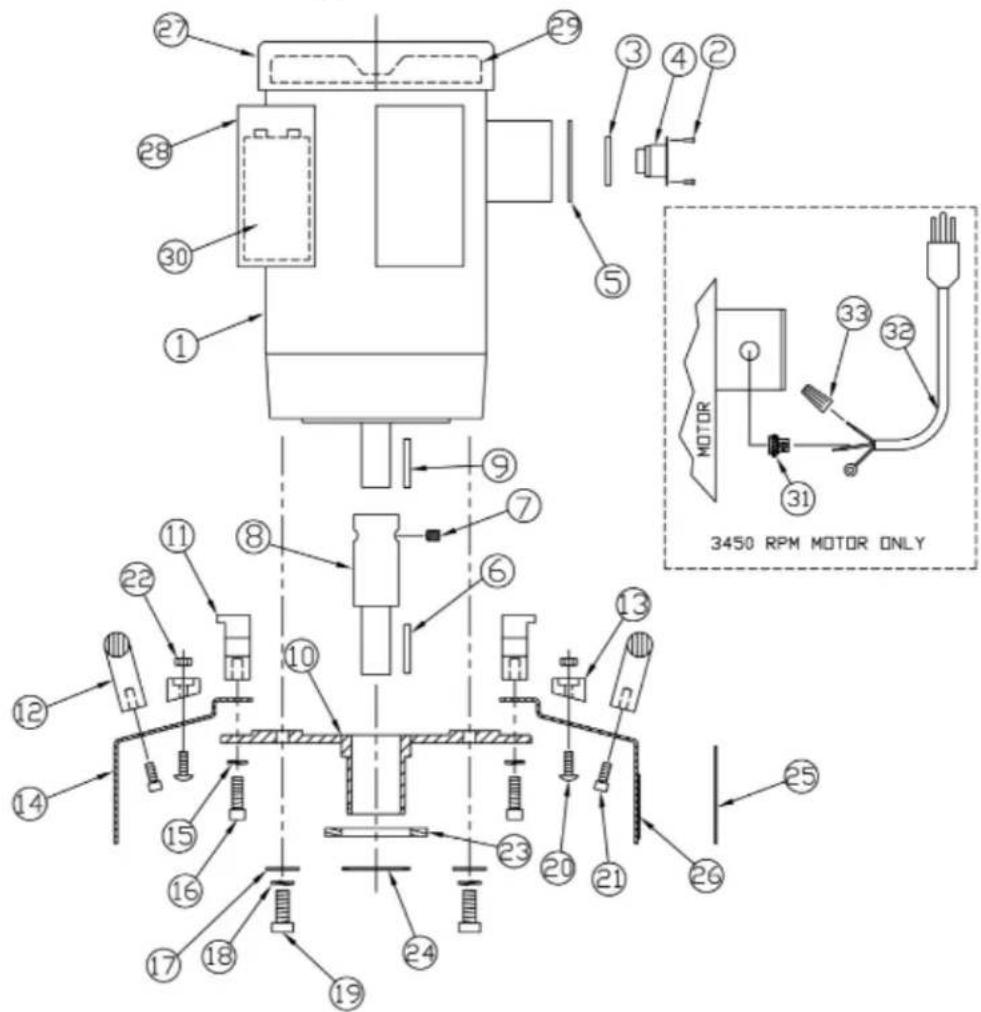
| ITEM | DESCRIPTION | QTY | PART NO. |
| 1 | 1.5 HP MOTOR ASSY, 115V (3450 RPM) | 1 | 299758 |
| 1.5 HP MOTOR ASSY, 115V (1760 RPM) | 1 | 497592 | |
| 2 | POP RIVET (1760 RPM only) | 2 | 318906 |
| 3 | SPACER (1760 RPM only) | 1 | 490873 |
| 4 | RECESS PLUG (1760 RPM only) | 1 | 490865 |
| 5 | COVER PLATE (1760 RPM only) | 1 | 290009 |
| 6 | KEY, .19 SQUARE X 2.05 | 1 | 491306 |
| 7 | SET SCREW, SHAFT EXTENSION | 2 | 490849 |
| 8 | MOTOR SHAFT EXTENSION | 1 | 490857 |
| 9 | KEY, SQUARE, .19 X 1.5 | 1 | 606243 |
| 10 | MOTOR MOUNT PLATE ASSY | 1 | 490326 |
| 11 | MOUNTING BRACKET | 2 | 606227 |
| 12 | BOWL HANDLE | 2 | 490385 |
| 13 | WEIGHT KNOB | 3 | 491632 |
| 14 | 16" OUTER BOWL ASSY | 1 | 296554 |
| 15 | WASHER, 5/16 LOCK | 4 | 316113 |
| 16 | SOCKET CAP SCREW, 5/16-18 X 1 | 4 | 490350 |
| 17 | WASHER, FLAT, .37 ID X .87 OD | 4 | 327433 |
| 18 | LOCK WASHER 3/8 | 4 | 368849 |
| ITEM | DESCRIPTION | QTY | PART NO. |
| 19 | 3/8-16 X 1" HEX BOLT | 4 | 368830 |
| 20 | ROUND HEAD SCREW, 1/4-20 X 3/4 | 3 | 342831 |
| 21 | SOCKET CAP SCREW, 1/4-20 X 5/8 | 4 | 457310 |
| 22 | NUT, NYLOCK 1/4-20 | 3 | 380784 |
| 23 | FELT GASKET | 1 | 493066 |
| 24 | 1.75 EXTERNAL SNAP RING | 1 | 491292 |
| 25 | RUBBER DUST SKIRT | 1 | 491640 |
| 26 | MALE HOOK & LOOP STRIP | 1 | 491659 |
| 27 | BALDOR FAN COVER FOR 115V | 1 | 499420 |
| 28 | CAPACITOR COVER BALDOR MOTOR | 2 | 295671 |
| 29 | COOLING FAN | 1 | 250783 |
| 30 | CAPACITOR, START,LEESON 3450 RPM | 1 | 600296 |
| CAPACITOR, RUN,LEESON 3450 RPM | 1 | 600288 | |
| CAPACITOR START,BALDOR 1760 RPM | 1 | 606235 | |
| CAPACITOR, RUN, BALDOR 1760 RPM | 1 | 242500 | |
| 31 | STRAIN RELIEF 3450 RPM ONLY | 1 | 497657 |
| 32 | PIGTAIL W/MALE PLUG 3450 RPM | 1 | 495786 |
| 33 | NUT, WIRE 3450 RPM ONLY | 2 | 350648 |
| 20# WEIGHT (OPTL) NOT SHOWN | 1 | 491691 |
16" Inner Bowl Drawing & Parts List

| ITEM | DESCRIPTION | QTY | PART NO. |
| 1 | 16" INNER BOWL W/BEARINGS SHAFT | 1 | 490539 |
| 2 | BOWL BEARING | 2 | 245666 |
| 3 | LARGE BEARING SPACER | 1 | 490571 |
| 4 | 2.87" INTERNAL SNAP RING | 1 | 490598 |
| 5 | OUTER PULLEY SHAFT | 3 | 490547 |
| 6 | DUST COVER ASSY 16" | 1 | 299987 |
| 7 | SEAL, BRUSH | 3 | 297747 |
| 8 | CENTER COG PULLEY 16 | 1 | 272507C |
| 9 | WASHER, FLAT, .344 ID X 1.25 OD | 1 | 295167 |
| 10 | WASHER, LOCK EXTERNAL TOOTH 3/8 | 1 | 605905 |
| 11 | BOLT, HEX 3/8-16 X 1.25 | 1 | 606278 |
| 12 | SHAFT SPACER | 3 | 490555 |
| ITEM | DESCRIPTION | QTY | PART NO. |
| 13 | 1.5" INTERNAL SNAP RING | 3 | 490466 |
| 14 | BALL BEARING W/ SEALS | 6 | 245321 |
| 15 | SMALL BEARING SPACER | 3 | 490474 |
| 16 | FLAT WASHER 16 MM OD | 3 | 490636 |
| 17 | NUT, NYLOK 5/8-11 | 3 | 490628 |
| 18 | BELT RETAINER PLATE ASSY (SET OF 3) INCLUDES 19, 20 & 21 | 1 | 603775 |
| 22 | ACCESSORY PINS (SET OF 12) | 1 | 602302 |
| 23 | HI PULLEY W/BEARINGS (CLOSEST TO FLOOR) | 1 | 491357 |
| 24 | MID PULLEY W/BEARINGS | 1 | 491330 |
| 25 | LO PULLEY W/BEARNIGS (CLOSEST TO MOTOR) | 1 | 491349 |
| 26 | WASHER, LOCK | 9 | 342858 |
| 27 | BOLT, HEX, 1/4-20 X 1/2 | 9 | 299618 |
| 28 | BELTS 210-L050 (SET OF 3) NOT SHOWN | 1 | 494097 |
Troubleshooting Guide
Problem: Motor will not run
1) Possible Cause: Power cord is not plugged in properly or damaged.
Possible Solution: Plug in power cord properly or replace power cord if damaged.
2) Possible Cause: Blown fuse or tripped circuit breaker at the wall panel.
Possible Solution: Replace fuse or reset circuit breaker. If this does not correct the problem have the machine checked by a qualified technician or an authorized dealer.
3) Possible cause: Onboard Circuit breaker tripped
Possible solution: Reset Circuit breaker in handle.
4) Possible Cause: Defective power cord or wiring.
Possible Solution: Check and replace if defective.
5) Possible Cause: Defective Switch
Possible Solution: Check Switch, replace if defective.
6) Possible Cause: Defective motor.
Possible Solution: Have motor checked by an authorized service center.
Problem: Machine bogs down and runs slow
1) Possible Cause: Defective capacitor or switch
Possible Solution: Have machine checked out by an authorized dealer.
2) Possible Cause: Circuit may be overloaded with more than one appliance.
Possible Solution: Plug floor machine into a dedicated power outlet. If the problem still exists there could be a short. Have machine checked out by an authorized dealer.
3) Possible Cause: Low line voltage in building.
Possible Solution: If wiring is old in the building have voltage checked by the power company.
Problem: Motor runs, driver will not rotate.
1) Possible Cause: Belt is broken.
Possible Solution: Replace Belt
Problem: Noisy machine or vibration
1) Possible Cause: Attachment is not level or securely attached.
Possible Solution: Level attachment and make sure all fasteners are secure.
2) Possible Cause: Defective motor.
Possible Solution: Contact the manufacturer or authorized service center.
Warranty Information
We guarantee to the original purchaser this floor machine against defects in material and workmanship for a period of 1 year from the date of delivery. Please note the following conditions pertaining to this warranty.
1) This warranty does not apply to any repair arising by reason of misuse, neglect, or abuse, or to proprietary parts.
2) Applies only to the original owner and is not transferable.
3) Machine will not have been dismantled or tampered with in any way.
4) Covered components proven defective will be repaired or replaced at no charge. Covered components include motors, bearings, belts and switches.
5) This Warranty is in lieu of and excludes every condition or warranty not herein expressly set out and all liability for any form of consequential loss or damage is hereby expressly excluded.
6) This Warranty is limited to repair or replacement of covered components and reasonable labor expenses.

- Safety, Operation Manual & Parts List
- OF16SH & OF16SL Multi-Purpose Floor Machine
- SAVE THESE INSTRUCTIONS
- Table of Contents
- General Instructions
- READ & FOLLOW ALL INSTRUCTIONS BEFORE USING THIS FLOOR MACHINE
- Silica Vacuum Warning
- Important Safety Instructions
- Grounding Instructions & Methods
- Improper use of the grounding plug can result in a risk of electric shock!
- Operating Instructions
- Installation & Changing of Accessory Tools
- Before Installation or Changing Attachments:
- Changing and Installation of Attachments
- Belt Changing Instructions
- Inner Bowl Removal Instructions
- Inner Bowl Bearing Replacement
- Installation Using a Press
- Installation without a Press
- An Important Detail
- Pulley Bearing Replacement
- General Safety Precautions
- Machine Maintenance
- Troubleshooting Guide
- Problem: Motor will not run
- Problem: Machine bogs down and runs slow
- Problem: Motor runs, driver will not rotate.
- Problem: Noisy machine or vibration
- Warranty Information
Brand : Onfloor Technologies
Model : OF16SL
Category : Floor polisher