
TAC-12CHB/NZW - Air purifier TCL - Free user manual and instructions
Find the device manual for free TAC-12CHB/NZW TCL in PDF.

| Product Type | Air Purifier |
| Brand | TCL |
| Model | TAC-12CHB/NZW |
| Dimensions (W x H x D) | 400 x 600 x 200 mm |
| Weight | 5.5 kg |
| Power Supply | 220-240 V, 50 Hz |
| Power Consumption | 55 W |
| Filtration System | Pre-filter, HEPA H13, Activated Carbon |
| CADR (Clean Air Delivery Rate) | 300 m³/h |
| Coverage Area | Up to 35 m² |
| Fan Speeds | 3 speeds (Low, Medium, High) |
| Timer Function | 1, 2, 4, 8 hours |
| Air Quality Indicator | Yes (PM2.5 sensor) |
| Noise Level | 30 - 55 dB(A) |
| Filter Replacement Indicator | Yes |
| Maintenance | Clean pre-filter every 2 weeks; replace HEPA filter every 6-12 months |
| Safety Features | Child lock, overheat protection, tip-over shut-off |
| Spare Parts Available | Replacement HEPA filters, pre-filters, remote control |
| Warranty | 2 years |
| Certifications | CE, RoHS |
Frequently Asked Questions - TAC-12CHB/NZW TCL
User questions about TAC-12CHB/NZW TCL
0 question about this device. Answer the ones you know or ask your own.
Ask a new question about this device
Download the instructions for your Air purifier in PDF format for free! Find your manual TAC-12CHB/NZW - TCL and take your electronic device back in hand. On this page are published all the documents necessary for the use of your device. TAC-12CHB/NZW by TCL.
USER MANUAL TAC-12CHB/NZW TCL
natural_image
Line drawing of a portable air purifier with wheels and top cover (no text or symbols)Zahvaljujemo se na odabiru našeg kvalitetnog uređaja.
Molimo pažljivo pročitati ove upute prije upotrebe. Za sva pitanja, obratite se stručnoj službi pomoći.
Prema IEC standardu:
- Ovaj uređaj nije namijenjen za uporabu od strane osoba (uključujući i djecu) sa ograničenim fizičkim, senzornim ili mentalnim sposobnostima ili nedostatkom iskustva i znanja, osim ako nisu pod nadzorom ili im se ne daju upute za uporabu uređaja od strane osobe odgovorne za njihovu sigurnost.
- Djecu treba nadzirati kako se ne bi igrala sa uređajem.
- Ako je kabel za napajanje oštećen, mora ga zamijeniti proizvođač, servisni agent ili slična kvalificirana osoba kako bi se izbjegle opasnosti.
- Uređaj će biti instaliran u skladu sa nacionalnim regulativama o električnim vodovima.
Posebne informacije u vezi s aparatima s rashladnim plinom R290
- Temeljito pročitajte sva upozorenja.
- Pri odmrzavanju i čišćenju uređaja, ne koristiti ne koristiti nikakve alate osim onih koji preporučuje proizvođačka tvrtka.
- Uređaj se mora postaviti na mjestu gde nema bilo kojih kontinuiranih izvora topline (npr otvoreni plamen, plin ili elektronski aparati u radu)
• Nemojte probijati i palitii.
• Rashladni plinovi mogu biti bez mirisa. - Uređaj se mora instalirati, koristiti i skladištiti na prostoru većem od 13 m ^2 .
natural_image
Symbol of a trash bin crossed with a diagonal line, no text or numbers presentNa vijeka trajanja proizvod se ne smije odlagati s radnim otpadom. Mora se odnijeti u centar lokalnih vlasti za sakupljanje diferenciranog otpada ili prodavaču koji pruža ovu uslugu. Odvojeno odlaganje kućanskog uređaja izbjegava moguće negativne posljedice po okolinu i zdravlje koje nastaju od neodgovarajućeg odlaganja i omogućava da se sastavni materijali oporave da bi se postigle značajne uštede u energiji i resursima. Kao podsjetnik na potrebu odvojenog odlaganja kućnih uređaja, proizvod ima oznaku kante na kotačima koja je prekrižena.

- Kontrolna ploča
- Ručka (obje strane)
- Kotačići
- Deflektor
- Prijamnik daljinskog upravljača
- Usisna rešetka
- Rešetka za izlaz zraka
- Usisna rešetka
- Napojni kabel
- Pričvršćivač utikača
- Srednje ispuštanje
- Ispust kondenzatora

PRIBOR
| DIJELOVI | NAZIV DIJELA | KOLIČINA |
   | Ispušno crijevoIzlaz cijeviUlaz cijevi | 1 komplekt |
 | Komplet klizača prozora | 1 komplekt |
 | Baterije za daljinski upravljač(2 * AAA 1,5V) | 1 komplekt |
 | Crijevo za odvod | 1 komplekt |
BILJEŠKA: Sve ilustracije u ovom priručniku postoje samo u svrhe objašnjavanja. Vaš uređaj se može malo razlikovati. Pazite da je sav pribor uklonjen s pakiranja prije uporabe.
ISPUST VRUĆEG ZRAKA
U Hladnom načinu uređaj se mora staviti blizu prozora ili otvora tako da se vrući ispušni zrak može odvesti vani.
Najprije postavite uređaj na ravan pod i pazite da postoji minimum od 18" (45 cm) zazora oko uređaja i u blizini jednog izvora napajanja utičnice kruga.
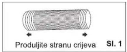
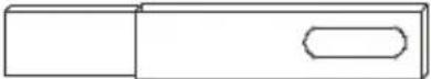
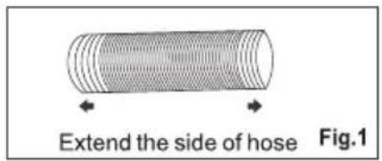
- Produljite bilo koju stranu crijeva (sl. 1) i zavrnite ulaz crijeva (sl. 2).
- Produljite drugu stranu crijeva i zavrnite ju na izlaz crijeva (sl. 3).
- Postavite ulaz crijeva u uređaj (sl. 4)
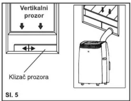
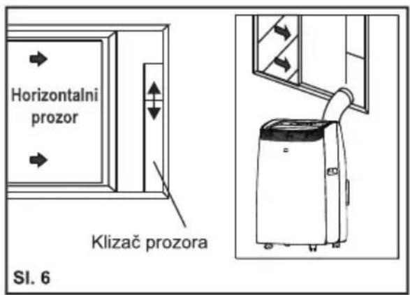
- Pričvrstite izlaz crijeva u komplet klizača prozora i zatvorite. (Sl. 5 &6).

natural_image
Diagram showing a cylindrical component with a curved arrow indicating rotation, labeled SI. 2 (no text or symbols on the diagram itself)
natural_image
Diagram of a cylindrical object with a curved arrow indicating rotation, labeled 'SI. 3' (no text or symbols on the object itself)

Vaš komplet klizača prozora je dizajniran da odgovara većini standardnih i horizontalnih primjena prozora: ipak, možda će biti potrebno za vas da izmijenite neke aspekte postupaka postavljanja za određene vrste prozora. Komplet klizača prozora može se pričvrstiti vijcima.
BILJEŠKA: Ako je otvor prozora manji od minimalne duljine kompleta klizača prozora, odsijecite kraj bez držača u njemu dovoljno kratko da odgovara u otvoru prozora. Nikada nemojte odsjeći rupu u kompletu klizača prozora.
POSTAVLJANJE KOMPLETA KLIZAČA PROZORA
1: Dijelovi:
A) Ploča
B) Ploča sa jednom rupom
C) Vijkom pričvrstite prozor na mjesto
2: Sastavljanje:
Kliznite Ploču B u Ploču A i podudarite na širinu prozora. Veličine prozora variraju. Prilikom određivanja širine prozora, pri mjerenju vodite računa da na sklopu kompleta prozora nema praznina i/ ili zračnih džepova.
- Učvrstite vijak u rupe koje odgovaraju
natural_image
Diagram showing a device connected to a pipe with a diagonal line crossing through it (no text or symbols present)natural_image
Simple diagram with two horizontal black lines inside a rectangle (no text or symbols)Način COOL (HLAĐENJA)
natural_image
Three abstract geometric shapes with black fill patterns, no text or symbols presentNačin DRY (SUHI)
Idealno za smanjenje vlažnosti u sobi (proljeće i jesen, vlažne prostorije u kišnim periodima itd.).
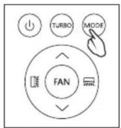
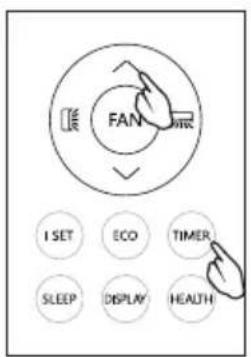
Način SMART (PAMETAN)
Uređaj automatski odabire hoće li raditi u hladnom, ventilatoru ili grijanju (samo na određenim modelima).
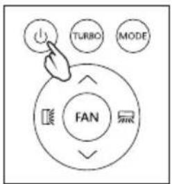
Za ispravno postavljanje ovog uređaja:
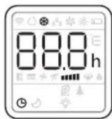
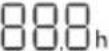
- Pritisnite gumb 🚙️ više puta dok zaslon ne prikaže kao ispod:
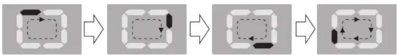
flowchart
graph LR
    A["3D Cube"] --> B["3D Cube with Dashed Arrow"]
    B --> C["3D Cube with Left Arrow and Right Arrow"]
    C --> D["3D Cube with Left Arrow and Right Arrow"]
- Odaberite traženu brzinu ventilatora pritiskom na gumb 🚙️.
Raspoložive su četiri brzine: Visoka / Srednja / Niska / Automatska.
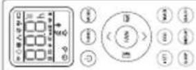
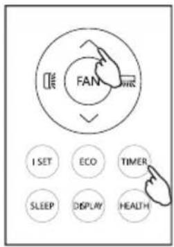
Tipki daljinskog uređaja
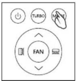
| Isključite / uključite klima uređaj. | |
| MODE(NAČIN) | Odaberite model rada: SMART (PAMETAN), COOL (HLADENJA), DRY (SUHI), FAN (VENTILATORA), HEAT (GRIJANJA). |
| (TEMP UP (TEMPERATURA VIŠE)) | Da biste povećali temperaturu podešavanja, produžite vrijeme u postavci TIMER (TAJMER). |
| (TEMP DN (TEMPERATURA NIŽE)) | Da biste smanjili temperaturu podešavanja, smanjite vrijeme u postavci TIMER (TAJMER). |
| Za vertikalno podešavanje smjera strujanja zraka (za ovaj model nije dostupno). | |
| Za vodoravno podešavanje smjera strujanja zraka. | |
| FAN(VENTILATORA) | Za podešavanje brzine ventilatora: auto, niska, srednja, visoka. |
| TURBO (TURBNO) | Za uključivanje/isključivanje TURBO (TURBNO) načina. |
| I SET (PRIMENITI) | Za aktiviranje funkcije I SET (PRIMENITI) (nije dostupno za ovaj model) |
| ECO | Za uključivanje/isključivanje ECO načina (nije dostupno za ovaj model) |
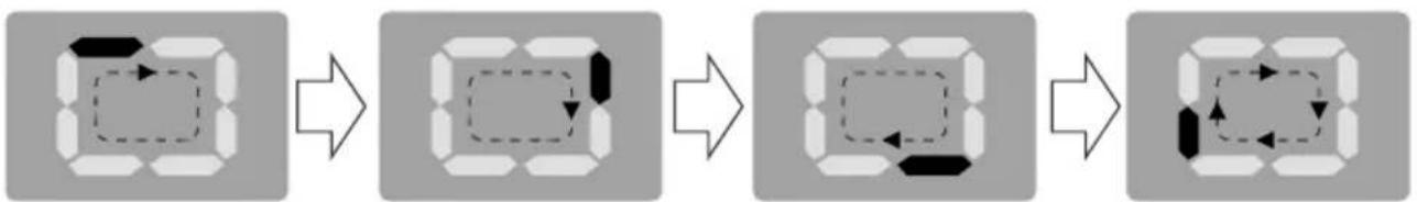
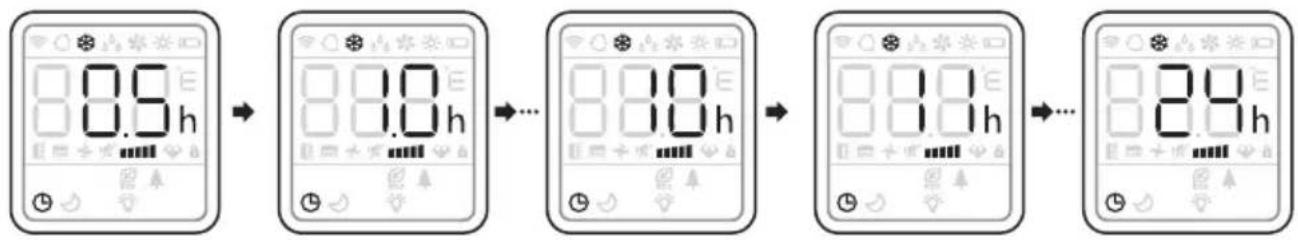
| TIMER(TAJMER) | Za uključivanje/isključivanje TIMER (TAJMER) funkcije. |
| SLEEP (MIROVANJA) | Za uključivanje/isključivanje SLEEP (MIROVANJA) načina. |
| DISPLAY (ZASLONA) | Za uključivanje/isključivanje LED svjetiljke (nije dostupno za ovaj model) |
| HEALTH (ZDRAVA) | Za uključivanje/isključivanje fukcije HEALTH (ZDRAVA) (nije dostupno za ovaj model) |
| Da biste aktivirali funkciju zaštite od djece, pritisnite tipke i zajedno više od 3 sekunde. |
⚠️Zaslon i neke funkcije daljinskog upravljača mogu se razlikovati ovisno o modelu.
Oblik i položaj tipki i pokazivača mogu se razlikovati ovisno o modelu, ali njihova je funkcija ista.
⚠️ Uređaj zvučnim signalom potvrđuje točan prijem svake tipke.
⚠️ Možda neke funkcije ne odgovaraju vašem klima uređaju, čut ćete zvučni signal kada pritisnete ove tipke, ali klima uređaj ne reagira, izvinjavamo se.

natural_image
Diagram of a handheld electronic device with a USB port and cable, showing internal components and a close-up of the cable (no text or symbols present)⚠️ Koristite dve velike 03 AAA(1,5V) baterije. Nemojte koristiti akumulatorske baterije.
PREBACITE JEDINICU TEMPERATURE
Pritisnite TURBO (TURBNO) gumb i držite je, a zatim podesite temperaturu.

NAČIN COOLING (HLAĐENJA)
Način hlađenja dozvoljava klima uređaju da ohladi prostoriju i istovremeno smanjuje vlažnost zraka.
- Za aktiviranje funkcije hlađenja (COOL(HLAĐENJA)), pritisnite (MODE(NAČIN)) gumb sve dok se znak ✿ ne pojavi na zaslonu.
- Sa Gumbma √ ili ∧ podesite temperaturu 18°C-32°C (64°F-90°F) niže od temperature u prostoriji.

NAČIN HEATING (GRIJANJA)
BILJEŠKA: Tijekom HEATING (GRIJANJA), uređaj može automatski aktivirati ciklus odmrzavanja, što je neophodno za čišćenje mraza na kondenzatoru kako bi se oporavila njegova funkcija izmjene topline. Ovaj postupak traje 2-10 minuta.
Tijekom odmrzavanja, ventilator prestaje sa radom. Posle odmrzavanja, automatski se nastavlja način HEATING (GRIJANJA).
- U ovom načinu rada morate pričekati nekoliko minuta da se aparat počne zagrijavati.
- U ovom načinu rada, ventilator može raditi u kratkim periodima, čak i ako se postigla određena temperatura.
• Voda se uklanja iz zraka i sakuplja u spremniku. - Kad se spremnik napuni, aparat se isključi i na zaslonu se pojavljuje „F L“ (pun spremnik). Poklopac spremnika mora se izvaditi i isprazniti. Iscurite svu vodu koja je ostala u lavoru. Kad se sva voda isprazni, vratite poklopac na mjesto.
- Kad se spremnik isprazni, aparat se ponovno pokreće.
NAČIN DRY (SUHI)
NAČIN SMART (PAMETAN)
- Za aktivaciju način rada SMART (PAMETAN), pritisnite MODE(NAČIN) dok se znak ☐ ne pojavi na zaslonu.
U SMART (PAMETAN) načinu, način rada klima uređaja se postavlja automatski.

flowchart
graph LR
    A["Square with arrow"] --> B["Hexagon with dashed line"]
    B --> C["Circle with dashed line and arrow"]
    C --> D["Hexagon with dashed line and arrow"]
    D --> E["Circle with dashed line and arrow"]
Svjetlost:
| Niska | Srednja | Visoka | Auto |
| (FLASH) |
PROTOK ZRAKA
• za postavljanje ove funkcije:
Odaberite način rada (cool (hlađenja), dry (suhi), fan (ventilatora), heat (grijanja)) kao sto je opisano više.
U načinu FAN(VENTILATORA) ili DRY(SUHI), funkcija SLEEP (MIROVANJA) ne može se postaviti.
BILJEŠKA: Kako bi ste poništili, pritisnite gumb TIMER (TAJMER) ponovo.
BILJEŠKA: U slučaju isključivanja, potrebno je ponovno postaviti TIMER OFF (ISKLJUČENO TAJMER).

flowchart
graph LR
    A["8.5h"] --> B["8.0h"]
    B --> C["..."]
    C --> D["8.0h"]
    D --> E["8.0h"]
    E --> F["..."]
    F --> G["8.0h"]
NAČIN TIMER (TAJMER) – PRIMENITI ZA TIMER ON (UKLJUČITE TAJMER)
Kako bi ste podesili automatsko uključivanje klima uređaja, pritisnite gumb TIMER (TAJMER) i posle toga gumb √ i ∧ kako bi ste postavili vreme. Pritisnite timer (tajmer) gumb ponovo kako bi ste započeli odbrojavanje.
BILJEŠKA: Kako bi ste poništili, pritisnite gumb TIMER (TAJMER) ponovo.
BILJEŠKA: U slučaju isključivanja, potrebno je ponovno postaviti TIMER ON (UKLJUČITE TAJMER).

flowchart
graph LR
    A["8.9h"] --> B["8.0h"]
    B --> C["..."]
    C --> D["8.0h"]
    D --> E["..."]
    E --> F["8.0h"]
Turbo funkcija (po izboru)
Za aktivaciju tubro funkcije, pritisnite TURBO (TURBNO) gumb, i znak ⚙️ će se pojaviti na zaslonu.
U načinu COOL (HLAĐENJA), kada izaberete TURBO (TURBNO) Uređaj će raditi brzo hlađenje sa najvećom brzinom ventilatora.
BILJEŠKA:
natural_image
Simple line drawing of a vertical air conditioner unit next to a checkmark and curved surface (no text or symbols)
natural_image
Illustration of a front air conditioner unit next to a cross symbol and wavy line, no text or labels presentSrednja odvodnja
Kada uređaj radi u Dry (Suhi) načinu, dolje možete odabrati način odvodnje.
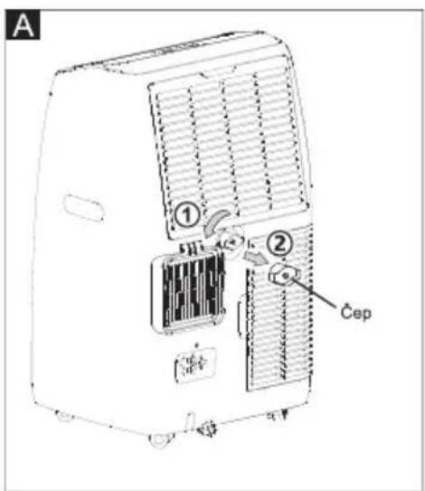
- Isključite uređaj iz izvor napajanja.
- Uklonite odvodni čep.(sl.A) Tijekom ove operacije može se izliti nešto preostale vode, pa imajte posudu za sakupljanje vode.
- Spojite odvodno crijevo (1/2 "ili 12,7 mm, možda nije u kompletu). (sl.B)
- Voda se može ispuštati kroz crijevo u posudu ili kantu.
- Uključite uređaj.
natural_image
Line drawing of an air conditioner unit with cooling fins and a cable inserted (no text or symbols)
BILJEŠKA:
Molimo pripazite da visina i presjek odvodnog crijeva ne smiju biti veći od izlaza za odvod, jer se spremnik za vodu neće ispustiti. (sl.C i sl.D)
natural_image
Simple line drawing of a vertical air conditioner unit with a curved ramp and a checkmark (no text or symbols)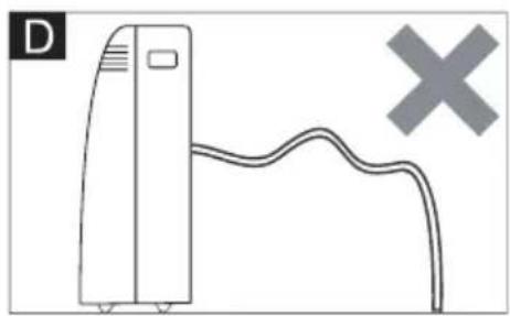
natural_image
Simple line drawing of a vertical device connected to a curved cable with a cross symbol (no text or labels)natural_image
Technical line drawing of an air conditioning unit with cooling fan and heat exchanger (no text or symbols)Upotrijebite usisavač za uklanjanje nakupina prašine s filtra. Ako je jako prljav, uronite u toplu vodu i isperite
nekoliko puta. Voda nikada ne smije biti vruća više od 40 °C (104 °F). Nakon pranja, ostavite filter da se osuši, a zatim na uređaj pričvrstite usisnu rešetku.
POČETAK SEZONSKIH PROVJERA
natural_image
Diagram of a refrigerant unit with heat exchanger and cooling elements (no text or labels)STROGO RADNO OKRUŽENJE:
Način Cooling (Hlađenjem): 18°C-35°C (64°F-95°F), 30%RH\~90%RH
Način Heating (Grijanjem): 10°C-25°C (50°F-77°F), 30%RH\~90%RH
natural_image
Line drawing of a portable air purifier with wheels and lid (no text or symbols)Thank you for selecting our quality appliance.
Please be sure to read this user manual carefully before using.
Any question, please contact the professional service for help.
| >100% of the total. |
IMPORTANT SAFEGUARDS
- Disconnect the appliance from its power source during service and when replacing parts and cleaning.
- The appliance shall not be installed in the laundry.
- Please note: Check the nameplate for the type of refrigerant gas used in your appliance.
- Specific information regarding appliances with refrigerant gas.
The appliance is recommended not to pierce the cooling circuit of the machine. At the end of its useful life, deliver the appliance to a special waste collection center for disposal.
GWP (Global Warming Potential): R410A: 2088, R134a: 1430, R290: 3, R32: 675.
- This hermetically sealed system contains fluoridated greenhouse gases.
- ENVIRONMENTAL INFORMATION: This unit contains fluoridated greenhouse gases covered by the Kyoto Protocol.
- Do not use this unit for functions other than those described in this instruction manual.
- Make sure the plug is plugged firmly and completely into the outlet. It can result in the risk of electric shock or fire.
- Do not plug other appliances into the same outlet, it can result in the risk of electric shock.
- Do not disassemble or modify the appliance or the power cord, it can result in the risk of electric shock or fire. All other services should be referred to a qualified technician.
- Do not place the power cord or appliance near a heater, radiator, or other heat source. It can result in the risk of electric shock or fire.
- This unit is equipped with a cord that has a earthed wire connected to an earthed pin or grounding tab. The plug must be plugged into a socket that is properly installed and earthed. Do not under any circumstances cut or remove the earthed pin or grounding tab from this plug.
- The unit should be used or store in such a way that it is protected from moisture e.g. condensation, splashed water, etc. Unplug unit immediately if this occurs.
- Always transport your appliance in a vertical position and place on a stable, level surface during use. If the unit is transported laying on its side it should be stood up and left unplugged for 6 hours.
- Always use the switch on the control panel or remote control to turn the unit off, and do not start or stop operation by plugging in or unplugging the power cord. It can result in the risk of electric shock.
- Do not touch the buttons on the control panel with your wet and damp fingers.
- Do not use hazardous chemicals to clean or come into contact with the unit. To prevent damage to the surface finish, use only a soft cloth to clean the appliance. Do not use wax, thinner, or a strong detergent. Do not use the unit in the presence of inflammable substance or vapor such as alcohol, insecticides, gasoline, etc.
- If the appliance is making unusual sounds or is emitting smoke or an unusual odor, unplug it immediately.
- Do not clean the unit with water. Water can enter the unit and damage the insulation, creating a shock hazard. If water enters the unit, unplug it immediately and contact Customer Service.
IMPORTANT SAFEGUARDS
- Utilize two or more people to lift and install the unit.
- Always grasp the plug when plugging in or unplugging the appliance. Never unplug by pulling on the cord. It can result in the risk of electrical shock and damage.
- Install the appliance on a sturdy, level floor capable of supporting up to 110lbs(50kg). Installation on a weak or unlevel floor can result in the risk of property damage and personal injury.
- If the appliance has the Wi-Fi function, the transmission power: less than 20dBm, and the radio frequency range is: 2412MHz-2472MHz.
- The appliance is compliant with the RE Directive (2014/53/EU).
According the EN standard:
- This appliance can be used by children aged from 8 years and above and persons with reduced physical, sensory or mental capabilities or lack of experience and knowledge if they have been given supervision or instruction concerning use of the appliance in a safe way and understand the hazards involved.
• Children shall not play with the appliance. - Cleaning and user maintenance shall not be made by children without supervision.
- If the supply cord is damaged, it must be replaced by the manufacturer, its service agent or a similarly qualified person in order to avoid a hazard.
- The appliance shall be installed in accordance with national wiring regulations.
- When the fuse is blown/circuit breaker is tripped, check the house fuse/circuit breaker box and replace fuse or reset breaker
• Details of type and rating of fuses: T; 3.15A; 250VAC.
According the IEC standard:
- This appliance is not intended for use by persons (including children) with reduced physical, sensory or mental capabilities, or lack of experience and knowledge, unless they have been given supervision or instruction concerning use of the appliance by a person responsible for their safety.
- Children should be supervised to ensure that they do not play with the appliance.
- If the supply cord is damaged, it must be replaced by the manufacturer, its service agent or similarly qualified persons in order to avoid a hazard.
- The appliance shall be installed in accordance with national wiring regulations.
Specific information regarding appliances with R290 refrigerant gas
• Thoroughly read all of the warnings.
- When defrosting and cleaning the appliance, do not use any tools other than those recommended by the manufacturing company.
- The appliance must be placed in an area without any continuous sources of ignition (for example: open flames, gas or electrical appliances in operation).
- Do not puncture and do not burn.
• Refrigerant gases can be odorless.
- The appliance must be installed, used and stored in an area that is greater than 13 m2.
• R290 is a refrigerant gas that complies with the European directives on the
IMPORTANT SAFEGUARDS
environment. Do not puncture any part of the refrigerant circuit.
- If the appliance is installed, operated or stored in a non-ventilated area, the room must be designed to prevent the accumulation of refrigerant leaks resulting in a risk of fire or explosion due to ignition of the refrigerant caused by electric heaters, stoves, or other sources of ignition.
- The appliance must be stored in such a way as to prevent mechanical failure.
- Individuals who operate or work on the refrigerant circuit must have the appropriate certification issued by an accredited organization that ensures competence in handling refrigerants according to a specific evaluation recognized by associations in the industry.
- Repairs must be performed based on the recommendations from the manufacturing company.
- Maintenance and repairs that require the assistance of other qualified personnel must be performed under the supervision of an individual specified in the use of flammable refrigerants.
- Do not use means to accelerate the defrosting process or to clean, other than those recommended by the manufacturer.
- The appliance shall be stored in a room without continuously operating open flames (for example an operating gas appliance) or other potential ignition sources (for example an operating electric heater, hot surfaces).
- All the work men who are engaging in the refrigeration system should bear the valid certification awarded by the authoritative organization and the qualification for dealing with the refrigeration system recognized by this industry. If it needs other technician to maintain and repair the appliance, they should be supervised by the person who bears the qualification for using the flammable refrigerant.
- It can only be repaired by the method suggested by the equipment's manufacturer.
- Do not pierce or burn.
- Be aware that the refrigerants may not contain an odor.
• Compliance with national gas regulations shall be observed.
- Keep ventilation openings clear of obstruction.
- The appliance shall be stored so as to prevent mechanical damage from occurring.
- A warning that the appliance shall be stored in a well-ventilated area where the room size corresponds to the room area as specified for operation.
- Any person who is involved with working on or breaking into a refrigerant circuit should hold a current valid certificate from an industry-accredited assessment authority, which authorizes their competence to handle refrigerants safely in accordance with an industry recognized assessment specification.
• Servicing shall only be performed as recommended by the equipment manufacturer.
- Maintenance and repair requiring the assistance of other skilled personnel shall be carried out under the supervision of the person competent in the use of flammable refrigerants.
- Appliance should be installed, operated and stored in a room with a floor area larger than the one indicated in the chart.
IMPORTANT SAFEGUARDS
| Quantity of R290 gas in charge(see rating label on the appliance)(g) | Minimum size of the site for useand storage( m^2 ) |
| m<152 | 4 |
| 152≤m≤185 | 9 |
| 186≤m≤225 | 11 |
| 226≤m≤270 | 13 |
| 271≤m≤290 | 14 |

natural_image
Three icon set: open book, open book with 'i' symbol, and open notebook with wrench (no text or symbols)caution, risk of fire
WARNING: System contains refrigerant under very high pressure. The system must be serviced by qualified persons only.
-
Transport of equipment containing flammable refrigerants (Annex CC.1) Compliance with the transport regulations.
-
Marking of equipment using signs (Annex CC.2) Compliance with local regulations.
-
Disposal of equipment using flammable refrigerants (Annex CC.3) Compliance with national regulations.
-
Storage of equipment/appliances (Annex CC.4) The storage of equipment should be in accordance with the manufacturer's instructions.
-
Storage of packed (unsold) equipment (Annex CC.5) Storage package protection should be constructed such that mechanical damage to the equipment inside the package will not cause a leak of the refrigerant charge. The maximum number of pieces of equipment permitted to be stored together will be determined by local regulations.
IMPORTANT SAFEGUARDS
- Information on servicing (Annex DD.3)
1) Checks to the area
Prior to beginning work on systems containing flammable refrigerants, safety checks are necessary to ensure that the risk of ignition is minimized. For repair to the refrigerating system, the following precautions shall be complied with prior to conducting work on the system.
2) Work procedure
Work shall be undertaken under a controlled procedure so as to minimize the risk of a flammable gas or vapor being present while the work is being performed.
3) General work area
All maintenance staff and others working in the local area shall be instructed on the nature of work being carried out. Work in confined spaces shall be avoided. The area around the workspace shall be sectioned off. Ensure that the conditions within the area have been made safe by control of flammable material.
4) Checking for presence of refrigerant
The area shall be checked with an appropriate refrigerant detector prior to and during work, to ensure the technician is aware of potentially flammable atmospheres. Ensure that the leak detection equipment being used is suitable for use with flammable refrigerants, i.e. non-sparking, adequately sealed or intrinsically safe.
5) Presence of fire extinguisher
If any hot work is to be conducted on the refrigeration equipment or any associated parts, appropriate fire extinguishing equipment shall be available to hand. Have a dry powder or CO2 fire extinguisher adjacent to the charging area.
6) No ignition sources
No person carrying out work in relation to a refrigeration system which involves exposing any pipe work that contains or has contained flammable refrigerant shall use any sources of ignition in such a manner that it may lead to the risk of fire or explosion. All possible ignition sources, including cigarette smoking, should be kept sufficiently far away from the site of installation, repairing, removing and disposal, during which flammable refrigerant can possibly be released to the surrounding space. Prior to work taking place, the area
around the equipment is to be surveyed to make sure that there are no flammable hazards or ignition risks. "No Smoking" signs shall be displayed.
7) Ventilated area
Ensure that the area is in the open or that it is adequately ventilated before breaking into the system or conducting any hot work. A degree of ventilation shall continue during the period that the work is carried out. The ventilation should safely disperse any released refrigerant and preferably expel it externally into the atmosphere.
IMPORTANT SAFEGUARDS
8) Checks to the refrigeration equipment
Where electrical components are being changed, they shall be fit for the purpose and to the correct specification. At all times the manufacturer's maintenance and service guidelines shall be followed. If in doubt consult the manufacturer's technical department for assistance.
The following checks shall be applied to installations using flammable refrigerants:
- The charge size is in accordance with the room size within which the refrigerant containing parts are installed;
– The ventilation machinery and outlets are operating adequately and are not obstructed;
- If an indirect refrigerating circuit is being used, the secondary circuit shall be checked for the presence of refrigerant;
- Marking to the equipment continues to be visible and legible. Markings and signs that are illegible shall be corrected;
- Refrigeration pipe or components are installed in a position where they are unlikely to be exposed to any substance which may corrode refrigerant containing components, unless the components are constructed of materials which are inherently resistant to being corroded or are suitably protected against being so corroded.
9) Checks to electrical devices
Repair and maintenance to electrical components shall include initial safety checks and component inspection procedures. If a fault exists that could compromise safety, then no electrical supply shall be connected to the circuit until it is satisfactorily dealt with. If the fault cannot be corrected immediately but it is necessary to continue operation, an adequate temporary solution shall be used. This shall be reported to the owner of the equipment so all parties are advised.
Initial safety checks shall include:
- That capacitors are discharged: this shall be done in a safe manner to avoid possibility of sparking;
- That there no live electrical components and wiring are exposed while charging, recovering or purging the system;
• That there is continuity of earth bonding.
- Repairs to sealed components (Annex DD.4)
1) During repairs to sealed components, all electrical supplies shall be disconnected from the equipment being worked upon prior to any removal of sealed covers, etc. If it is absolutely necessary to have an electrical supply to equipment during servicing, then a permanently operating form of leak detection shall be located at the most critical point to warn of a potentially hazardous situation.
IMPORTANT SAFEGUARDS
2) Particular attention shall be paid to the following to ensure that by working on electrical components, the casing is not altered in such a way that the level of protection is affected.
This shall include damage to cables, excessive number of connections, terminals not made to original specification, damage to seals, incorrect fitting of glands, etc.
Ensure that apparatus is mounted securely.
Ensure that seals or sealing materials have not degraded such that they no longer serve the purpose of preventing the ingress of flammable atmospheres. Replacement parts shall be in accordance with the manufacturer's specifications.
NOTE: The use of silicon sealant may inhibit the effectiveness of some types of leak detection equipment. Intrinsically safe components do not have to be isolated prior to working on them.
- Repair to intrinsically safe components (Annex DD.5)
Do not apply any permanent inductive or capacitance loads to the circuit without ensuring that this will not exceed the permissible voltage and current permitted for the equipment in use.
Intrinsically safe components are the only types that can be worked on while live in the presence of a flammable atmosphere. The test apparatus shall be at the correct rating.
Replace components only with parts specified by the manufacturer. Other parts may result in the ignition of refrigerant in the atmosphere from a leak.
- Cabling (Annex DD.6)
Check that cabling will not be subject to wear, corrosion, excessive pressure, vibration, sharp edges or any other adverse environmental effects. The check shall also take into account the effects of aging or continual vibration from sources such as compressors or fans.
- Detection of flammable refrigerants (Annex DD.7)
Under no circumstances shall potentially sources of ignition be used in the searching for or detection of refrigerant leaks. A halide torch (or any other detector using a naked flame) shall not be used.
- Leak detection methods (Annex DD.8)
The following leak detection methods are deemed acceptable for systems containing flammable refrigerants.
Electronic leak detectors shall be used to detect flammable refrigerants, but the
IMPORTANT SAFEGUARDS
sensitivity may not be adequate, or may need re-calibration. (Detection equipment shall be calibrated in a refrigerant-free area.) Ensure that the detector is not a potential source of ignition and is suitable for the refrigerant used. Leak detection equipment shall be set at a percentage of the LFL of the refrigerant and shall be calibrated to the refrigerant employed and the appropriate percentage of gas (25 % maximum) is confirmed.
Leak detection fluids are suitable for use with most refrigerants but the use of detergents containing chlorine shall be avoided as the chlorine may react with the refrigerant and corrode the copper pipe-work.
If a leak is suspected, all naked flames shall be removed/ extinguished.
If a leakage of refrigerant is found which requires brazing, all of the refrigerant shall be recovered from the system, or isolated (by means of shut off valves) in a part of the system remote from the leak. Oxygen free nitrogen (OFN) shall then be purged through the system both before and during the brazing process.
12. Removal and evacuation (Annex DD.9)
When breaking into the refrigerant circuit to make repairs – or for any other purpose – conventional procedures shall be used. However, it is important that best practice is followed since flammability is a consideration. The following procedure shall be adhered to:
- Remove refrigerant;
• Purge the circuit with inert gas; - Evacuate;
• Purge again with inert gas; - Open the circuit by cutting or brazing.
The refrigerant charge shall be recovered into the correct recovery cylinders. The system shall be "flushed" with OFN to render the unit safe. This process may need to be repeated several times. Compressed air or oxygen shall not be used for this task. Flushing shall be achieved by breaking the vacuum in the system with OFN and continuing to fill until the working pressure is achieved, then venting to atmosphere, and finally pulling down to a vacuum. This process shall be repeated until no refrigerant is within the system. When the final OFN charge is used, the system shall be vented down to atmospheric pressure to enable work to take place. This operation is absolutely vital if brazing operations on the pipe-work are to take place.
Ensure that the outlet for the vacuum pump is not close to any ignition sources and there is ventilation available.
13. Charging procedures (Annex DD.10)
In addition to conventional charging procedures, the following requirements shall be followed.
IMPORTANT SAFEGUARDS
- Ensure that contamination of different refrigerants does not occur when using charging equipment. Hoses or lines shall be as short as possible to minimize the amount of refrigerant contained in them.
– Cylinders shall be kept upright. - Ensure that the refrigeration system is earthed prior to charging the system with refrigerant.
- Label the system when charging is complete (if not already).
– Extreme care shall be taken not to overfill the refrigeration system.
Prior to recharging the system, it shall be pressure tested with OFN. The system shall be leak tested on completion of charging but prior to commissioning. A follow up leak test shall be carried out prior to leaving the site.
14. Decommissioning (Annex DD.11)
Before carrying out this procedure, it is essential that the technician is completely familiar with the equipment and all its detail. It is recommended good practice that all refrigerants are recovered safely. Prior to the task being carried out, an oil and refrigerant sample shall be taken in case analysis is required prior to re-use of reclaimed refrigerant. It is essential that electrical power is available before the task is commenced.
a) Become familiar with the equipment and its operation.
b) Isolate system electrically.
c) Before attempting the procedure ensure that:
- Mechanical handling equipment is available, if required, for handling refrigerant cylinders;
- All personal protective equipment is available and being used correctly;
• The recovery process is supervised at all times by a competent person; - Recovery equipment and cylinders conform to the appropriate standards.
d) Pump down refrigerant system, if possible.
e) If a vacuum is not possible, make a manifold so that refrigerant can be removed from various parts of the system.
f) Make sure that cylinder is situated on the scales before recovery takes place.
g) Start the recovery machine and operate in accordance with manufacturer's instructions.
h) Do not overfill cylinders. (No more than 80 % volume liquid charge).
i) Do not exceed the maximum working pressure of the cylinder, even temporarily.
j) When the cylinders have been filled correctly and the process completed, make sure that the cylinders and the equipment are removed from site promptly and all isolation valves on the equipment are closed off.
IMPORTANT SAFEGUARDS
k) Recovered refrigerant shall not be charged into another refrigeration system unless it has been cleaned and checked.
- Labelling (Annex DD.12)
Equipment shall be labelled stating that it has been de-commissioned and emptied of refrigerant. The label shall be dated and signed. Ensure that there are labels on the equipment stating the equipment contains flammable refrigerant.
- Recovery (Annex DD.13)
When removing refrigerant from a system, either for servicing or decommissioning, it is recommended good practice that all refrigerants are removed safely. When transferring refrigerant into cylinders, ensure that only appropriate refrigerant recovery cylinders are employed. Ensure that the correct number of cylinders for holding the total system charge is available. All cylinders to be used are designated for the recovered refrigerant and labelled for that refrigerant (i.e. special cylinders for the recovery of refrigerant).
Cylinders shall be complete with pressure relief valve and associated shut-off valves in good working order. Empty recovery cylinders are evacuated and, if possible, cooled before recovery occurs.
The recovery equipment shall be in good working order with a set of instructions concerning the equipment that is at hand and shall be suitable for the recovery of flammable refrigerants. In addition, a set of calibrated weighing scales shall be available and in good working order. Hoses shall be complete with leak-free disconnect couplings and in good condition. Before using the recovery machine, check that it is in satisfactory working order, has been properly maintained and that any associated electrical components are sealed to prevent ignition in the event of a refrigerant release. Consult manufacturer if in doubt.
The recovered refrigerant shall be returned to the refrigerant supplier in the correct recovery cylinder, and the relevant Waste Transfer Note arranged. Do not mix refrigerants in recovery units and especially not in cylinders.
If compressors or compressor oils are to be removed, ensure that they have been evacuated to an acceptable level to make certain that flammable refrigerant does not remain within the lubricant. The evacuation process shall be carried out prior to returning the compressor to the suppliers. Only electric heating to the compressor body shall be employed to accelerate this process. When oil is drained from a system, it shall be carried out safely.
Competence of service personnel General
IMPORTANT SAFEGUARDS
Special training additional to usual refrigerating equipment repair procedures is required when equipment with flammable refrigerants is affected.
In many countries, this training is carried out by national training organizations that are accredited to teach the relevant national competency standards that may be set in legislation.
The achieved competence should be documented by a certificate.
Training
The training should include the substance of the following:
Information about the explosion potential of flammable refrigerants to show that flammables may be dangerous when handled without care.
Information about potential ignition sources, especially those that are not obvious, such as lighters, light switches, vacuum cleaners, electric heaters.
Information about the different safety concepts:
Unventilated – (see Clause GG.2) Safety of the appliance does not depend on ventilation of the housing. Switching off the appliance or opening of the housing has no significant effect on the safety. Nevertheless, it is possible that leaking refrigerant may accumulate inside the enclosure and flammable atmosphere will be released when the enclosure is opened.
Ventilated enclosure – (see Clause GG.4) Safety of the appliance depends on ventilation of the housing. Switching off the appliance or opening of the enclosure has a significant effect on the safety. Care should be taken to ensure a sufficient ventilation before.
Ventilated room – (see Clause GG.5) Safety of the appliance depends on the ventilation of the room. Switching off the appliance or opening of the housing has no significant effect on the safety. The ventilation of the room shall not be switched off during repair procedures.
Information about the concept of sealed components and sealed enclosures according to IEC 60079-15:2010.
Information about the correct working procedures:
a) Commissioning
- Ensure that the floor area is sufficient for the refrigerant charge or that the ventilation duct is assembled in a correct manner.
- Connect the pipes and carry out a leak test before charging with refrigerant.
- Check safety equipment before putting into service.
b) Maintenance
- Portable equipment shall be repaired outside or in a workshop specially equipped for servicing units with flammable refrigerants.
- Ensure sufficient ventilation at the repair place.
- Be aware that malfunction of the equipment may be caused by refrigerant loss and a refrigerant leak is possible.
- Discharge capacitors in a way that won't cause any spark. The standard procedure to short circuit the capacitor terminals usually creates sparks.
- Reassemble sealed enclosures accurately. If seals are worn, replace them.
- Check safety equipment before putting into service.
c) Repair
- Portable equipment shall be repaired outside or in a workshop specially equipped for
IMPORTANT SAFEGUARDS
servicing units with flammable refrigerants.
- Ensure sufficient ventilation at the repair place.
- Be aware that malfunction of the equipment may be caused by refrigerant loss and a refrigerant leak is possible.
- Discharge capacitors in a way that won't cause any spark.
- When brazing is required, the following procedures shall be carried out in the right order:
- Remove the refrigerant. If the recovery is not required by national regulations, drain the refrigerant to the outside. Take care that the drained refrigerant will not cause any danger. In doubt, one person should guard the outlet. Take special care that drained refrigerant will not float back into the building.
• Evacuate the refrigerant circuit.
- Purge the refrigerant circuit with nitrogen for 5 min.
- Evacuate again.
- Remove parts to be replaced by cutting, not by flame.
- Purge the braze point with nitrogen during the brazing procedure.
- Carry out a leak test before charging with refrigerant.
- Reassemble sealed enclosures accurately. If seals are worn, replace them.
- Check safety equipment before putting into service.
d) Decommissioning
- If the safety is affected when the equipment is put out of service, the refrigerant charge shall be removed before decommissioning.
- Ensure sufficient ventilation at the equipment location.
- Be aware that malfunction of the equipment may be caused by refrigerant loss and a refrigerant leak is possible.
- Discharge capacitors in a way that won't cause any spark.
- Remove the refrigerant. If the recovery is not required by national regulations, drain the refrigerant to the outside. Take care that the drained refrigerant will not cause any danger. In doubt, one person should guard the outlet. Take special care that drained refrigerant will not float back into the building.
• Evacuate the refrigerant circuit.
- Purge the refrigerant circuit with nitrogen for 5 min.
- Evacuate again.
- Fill with nitrogen up to atmospheric pressure.
- Put a label on the equipment that the refrigerant is removed.
e) Disposal
- Ensure sufficient ventilation at the working place.
- Remove the refrigerant. If the recovery is not required by national regulations, drain the refrigerant to the outside. Take care that the drained refrigerant will not cause any danger. In doubt, one person should guard the outlet. Take special care that drained refrigerant will not float back into the building.
• Evacuate the refrigerant circuit.
- Purge the refrigerant circuit with nitrogen for 5 min.
- Evacuate again.
- Cut out the compressor and drain the oil.
SOME NOTIONS ON HUMIDITY
This product is factory equipped with a power supply cord that has a three-pronged grounded plug. It must be plugged into a mating grounding type receptacle in accordance with the National Electrical Code and applicable local codes and ordinances. If the circuit does not have a grounding type receptacle, it is the responsibility and obligation of the customer to exchange the existing receptacle in accordance with the National Electrical Code and applicable local codes and ordinances. The third ground prong should not, under any circumstances, be cut or removed. Never use the cord, the plug or the appliance when they show any sign of damage. Do not use your appliance with an extension cord unless it has been checked and tested by a qualified electrical supplier. Improper connection of the grounding plug can result in risk of fire, electric shock and/or injury to persons associated with the appliance. Check with a qualified service representative if in doubt that the appliance is properly grounded.
ELECTRICAL CONNECTIONS
Before plugging the appliance into the mains socket, check that:
- The mains power supply corresponds to the value indicated on the rating plate on the back of the appliance.
- The power socket and electrical circuit are adequate for the appliance.
- The mains socket matches the plug. If this is not the case, have the plug replaced.
- The mains socket is adequately earthed. Failure to follow these important safety instructions absolves the manufacturer of all liability.
Important information for correct disposal of the product in accordance with EC Directive 2012/19/EU.

natural_image
Symbol of a trash bin crossed with no text or numbers, representing environmental protection (no text present)At the end of its working life, the product must not be disposed of as urban waste. It must be taken to a special local authority differentiated waste collection center or to a dealer providing this service. Disposing of a household appliance separately avoids possible negative consequences for the environment and health deriving from inappropriate disposal and enables the constituent materials to be recovered to obtain significant savings in energy and resources. As a reminder of the need to dispose of household appliances separately, the product is marked with a crossed-out wheeled dustbin.

- Control panel
- Handle (both sides)
- Castors
- Deflector
- Remote control receiver
- Intake grille
- Air outlet grille
- Intake grille
- Power cable
- Plug fixer
- Middle drainage
- Condenser drain

ACCESSORIES
| PARTS | PARTS NAME | QUANTITY |
   | Exhaust hoseHose outletHose inlet | 1 set |
 | Window slider kit | 1 set |
 | Remote ControlBatteries(2 * AAA 1.5V) | 1 set |
 | Drain Hose | 1 set |
Note: All the illustrations in this manual are for explanatory purposes only. Your appliance may be slightly different. Be sure all accessories are removed from the packing before use.
EXHAUSTING HOT AIR
In the Cool Mode the appliance must be placed close to a window or opening so that the warm exhaust air can be ducted outside.
First position unit on a flat floor and make sure there's a minimum of 18" (45cm) clearance around the unit, and is within the vicinity of a single circuit outlet power source.
- Extend either side of the hose (Fig.1) and screw the hose inlet (Fig.2).
- Extend the other side of the hose and screw it to the hose outlet (Fig.3).
- Install the hose inlet into the unit (Fig.4).
- Affix the hose outlet into the window slider kit and seal. (Fig.5 &6).


natural_image
Diagram showing a cylindrical object with a curved arrow indicating rotation, labeled Fig.2 (no text or symbols on the diagram itself)
natural_image
Diagram of a cylindrical object with a curved opening, labeled Fig.3 (no text or symbols on the object itself)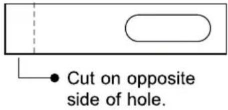
Your window slider kit has been designed to fit most standard vertical and horizontal window applications; however, it may be necessary for you to modify some aspects of the installation procedures for certain types of windows. The window slider kit can be fastened with screws.
NOTE: If the window opening is less than the minimum length of the window slider kit, cut the end without the hold in it short enough to fit in the window opening. Never cut out the hole in window slider kit.


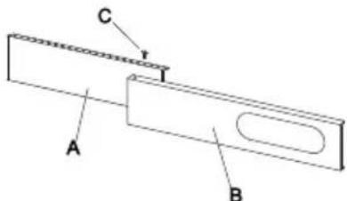
WINDOW SLIDER KIT INSTALLATION
1: Parts:
A) Panel
B) Panel with one hole
C) Screw to lock window kit in place
2: Assembly:
Slide Panel B into Panel A and size to widow width. Windows sizes vary. When sizing the window width, be sure that the window kit assembly is free from gaps from gaps and/or air pockets when taking measurements.
3. Lock the screw into the holes that correspond With the width that your window requires to ensure that there are no gaps or air pockets in the window kit assembly after installation.

LOCATION
- The unit should be placed on a firm foundation to minimize noise and vibration. For safe and secure positioning, place the unit on a smooth, level floor strong enough to support the unit.
- The unit has casters to aid placement, but it should only be rolled on smooth, flat surfaces. Use caution when rolling on carpeted surfaces. Use caution and Protect floors when rolling over wood floors. Do not attempt to roll the unit over objects.
- The unit must be placed within reach of a properly rated grounded socket.
- Never place any obstacles around the air inlet or outlet of the unit.
- Allow at least 18" (45cm) of around and above space away from the wall for efficient working.
- The hose can be extended, but it is the best to keep the length to minimum required. Also make sure that the hose does not have any sharp bends or sags.

natural_image
Diagram showing a device connected to a curved pipe with diagonal lines, no text or symbols presentDESCRIPTION OF THE DISPLAY SCREEN
The control panel is on the top of the appliance, enables you to manage part functions without remote controller, but to fully exploit its potential, you must use the remote controller.

- Timer button
2.Fan speed button
3.Decrease button - Display screen
5.Increase button
6.MODE button
7.ON/OFF button
A Mode symbol
B Fan speed symbol
C Sleep symbol
D Timer symbol
E WiFi symbol **
“*” means the heat symbol only the heat pump model have this function.
“**” means only WIFI model have this function.
Note: When the unit is connected with phone, the WIFI symbol is light on, and how to connected with phone, please see the wifi manual.
TURNING THE APPLIANCE ON
Plug into the mains socket, then the appliance is standby. Press the ⏻ button to make the appliance turn on. The last function active when it was turned off will appear.
natural_image
Simple diagram with two horizontal black lines inside a rectangle (no text or symbols)COOL mode
Ideal for hot muggy weather when you need to cooling and dehumidify the room.
To set this mode correctly:
- Press the ⚙️ button a number of times until the "Cool" symbol appears.
- Select the target temperature 18^ C-32^ C (64°F-90°F) by pressing the △ or ▽ button until the corresponding value is displayed.
- Select the required fan speed by pressing the ✧ button.
Four speeds are available: High / Medium / Low / Auto.
DESCRIPTION OF THE DISPLAY SCREEN
The most suitable temperature for the room during the summer varies from 24^ C to 27^ C ( 75^ F to 81^ F). You are recommended, however, not to set a temperature much below the outdoor temperature. The fan speed difference is more noticeable when the appliance is under Fan mode but may not be noticeable under Cool mode.
HEAT mode \*
“*” means only the heat pump model have this function.
To set this mode correctly:
- Press the ⚙️ button a number of times until the Heat symbol appears.
- Select the target temperature 13^ C-27^ C(55^ F-81^ F) by pressing the △ or ▽ button until the corresponding value is displayed.
- Select the required fan speed by pressing the ✿ button. Four speeds are available: High / Medium / Low / Auto.
• Water is removed from the air and collected in the tank.
- When the tank is full, the appliance shuts down and “ F_L ” (full tank) appears on the display. The tank cap must be extracted and emptied. Run off all water left into a basin. When all the water has been drained, put the cap back in place.
- When the tank has been emptied, the appliance starts up again.
NOTE:
- When operating in very cold rooms, the appliance defrosts automatically, momentarily interrupting normal operation. During this operation, it is normal for the noise made by the appliance to change.
- In this mode, you may have to wait for a few minutes before the appliance starts giving out hot air.
- In this mode, the fan may operate for short periods, even though the set temperature has already been reached.
DESCRIPTION OF THE DISPLAY SCREEN
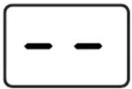
FAN mode
When using the appliance in this mode, the air hose does not need to be attached.
- Press the ⚙️ button a number of times until the "Fan" symbol appears.
- Select the required fan speed by pressing the ✧ button. Three speeds are available: High / Medium / Low.
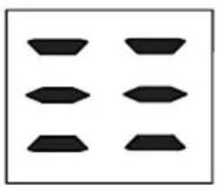
The screen display “==” as high speed, “==” as medium speed, “-” as low speed.
natural_image
Pure geometric pattern of six black shapes arranged in a 2x2 grid (no text or symbols)
natural_image
Four black geometric shapes arranged in a 2x2 grid on white background (no text or symbols)
natural_image
Two black geometric shapes on a white background, no text or symbols presentDRY mode
Ideal to reduce room humidity (spring and autumn, damp rooms rainy periods, etc.).
In dry mode, the appliance should be prepared in the same way as for cool mode, with the air exhaust hose attached to enable the moisture to be discharged outside.

To set this mode correctly:
- Press the ⚙️ button a number of times until the Dry symbol appears. The screen display "dh".
- In this mode, fan speed is selected automatically by the appliance and cannot be set manually.
SMART mode
The appliance chooses automatically whether to operate in cool, fan or heat (certain models only) mode.
To set this mode correctly:
- Press the ⚙ MODE button a number of times until the screen show like below:
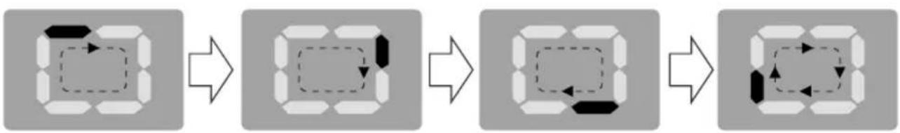
flowchart
graph LR
    A["Step 1: Dashed box with arrow"] --> B["Step 2: Solid box with arrow"]
    B --> C["Step 3: Dashed box with arrow"]
    C --> D["Step 4: Solid box with arrow"]
    D --> E["Step 5: Solid box with arrow"]
DESCRIPTION OF THE DISPLAY SCREEN
- Select the required fan speed by pressing the ✿ button. Four speeds are available: High / Medium / Low / Auto.
If the appliance is cooling only model, the unit operates in Fan mode, when the room temperature is below 23^ C ( 73^ F), and Cool mode when the room temperature is above 23^ C ( 73^ F).
If the appliance is cooling and heating model, the unit operates in Heat mode when the room temperature is below 20^(68^) , and Fan mode when the room temperature is from 20^(68^) to 23^(73^) , and Cool mode when the room temperature is above 23^(73^) .
SETTING THE TIMER
-This timer can be used to delay the appliance start-up or shutdown, this avoids wasting electricity by optimizing operating periods.
Programming start up
- Turn on the appliance, choose the mode you want, for example cool, 24°C, high fan speed. Turn off the appliance.
- Press the Timer button, the 📋 symbol and number of hours flash.
- Press the 📊 button to set the number of hours delay before the appliance comes on. The timer can set in intervals of 1 hours up to 24 hours.
- A few second after set, the setting is memorized, the timer indicator is light and the display shows that the appliance is in standby.
- Press again the Timer button 📊 or the ⏻ button, the timer will be canceled, and the "Timer" symbol will disappear from screen.
Programming shut down
- When the appliance is running, press the ⏻ button, the Timer indicator and the hours flash.
- Press the 📊 button to set the number of hours delay before the appliance comes on. The timer can set in intervals of 1 hours up to 24 hours.
- A few second after set, the setting is memorized, the timer indicator is light and the display shows the current mode. At the end of the set time the unit automatically turns to standby mode.
- Press again the Timer button 📋 or the ⏻ button, the timer will be canceled, and the "Timer" symbol will disappear from screen.
DESCRIPTION OF THE DISPLAY SCREEN
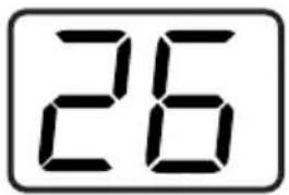
Switch the unit of temperature
When the appliance is running, hold on "▽" and "△" button together 3 seconds by the same time, then you can change the unit of temperature.
For example:
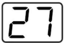
Before change, in cool mode, the screen display like fig1.
After change, in cool mode, the screen display like fig2.

Fig.1

Fig.2
The following functions below are optional. Please refer to the real object, just because these functions only belong to some model.
Wi-fi function
- In the stand-by, press “✿” button six times in four seconds to reset the Wi-Fi signal, so that the appliance will “beep” twice.
Then please refer to Wi-Fi connection specification to connect the appliance. If it is successful, the Wi-Fi indicator light on operational panel will be lightened.
DESCRIPTION OF THE DISPLAY SCREEN
SELF-DIAGNOSIS
The appliance has a self-diagnosis system to identify a number of malfunctions.
Error messages are displayed on the appliance display.
| IF IS DISPLAYED | WHAT SHOULD I DO? |
 PROBE FAILURE (sensor damaged) PROBE FAILURE (sensor damaged) | If this is displayed, contact your local authorize service center. |
 FULL TANK (safety tank full) FULL TANK (safety tank full) | Empty the internal safety tank,following the instructions in the “End of season operations”paragraph. |

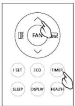
Remote controller buttons
| To turn on/off the air conditioner. | |
| MODE | To select the operation mode: SMART, COOL, DRY, FAN, HEAT. |
| (TEMP UP) | To increase the setting temperature, lengthen the time in TIMER setting. |
| (TEMP DN) | To decrease the setting temperature, reduce the time in TIMER setting. |
| To adjust the air flow direction vertically (No available for this model). | |
| To adjust the air flow direction horizontally. | |
| FAN | To adjust the fan speed: auto, low, mid, high. |
| TURBO | To switch on/off the TURBO mode. |
| I SET | To activate the function of I SET (No available for this model). |
| ECO | To switch on/off the ECO mode (No available for this model). |
| TIMER | To switch on/off the TIMER function. |
| SLEEP | To switch on/off the SLEEP mode. |
| DISPLAY | To switch on/off the LED display light (No available for this model). |
| HEALTH | To switch on/off the HEALTH function (No available for this model). |
| To activate the function of Child Lock, press ∧ and ∨ buttons together for more than 3 seconds. |
The display and some functions of the remote control may vary according to the model.
The shape and position of buttons and indicators may vary according to the model, but their function is the same.
The unit confirms the correct reception of each button with a beep.
There might some functions not fit for your air conditioner, you will hear a beep when you press these buttons, but air conditioner does not response, we express our apologies.
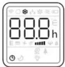
Remote controller DISPLAY, meaning of symbols on the liquid crystal display

| [7C05] | SMART MODE indicator |
| [KOZA] | COOLING MODE indicator |
| [X630] | DRY MODE indicator |
| [Y222] | FAN MODE indicator |
 | HEATING MODE indicator |
 | BATTERY indicator |
 | FLAP SWING (Air flow) indicator |
 | TEMPERATURE/ CLOCK indicator |
 | FAN SPEED indicator |
 | AUTO FAN indicator |
 | TIMER indicator |
| [2244] | SLEEP MODE indicator |
| [9CDY] | TURBO indicator |
| [S4CY] | MUTE indicator (No available for this model). |
 | ECO indicator (No available for this model). |
 | HEALTHY indicator (No available for this model). |
| [XCKX] | DISPLAY LIGHT indicator (No available for this model). |
REMOTE CONTROL MANUAL
√ Point the remote control at the receiver on the appliance.
√ The remote control must be no more than 7 meters away from the appliance (without obstacles between the remote control and the receiver).
√ The remote control must be handled with extreme care.

Do not drop it or expose it to direct sunlight or sources of heat.
If the remote control does not work, please try to take out the battery, and put it back.
Replacement of Batteries
Remove the battery cover plate from the rear of the remote controller, by sliding it in the direction of the arrow.
Install the batteries according the direction (+and -) shown on the Remote
Controller. Reinstall the battery cover by sliding it into place.

natural_image
Diagram of a handheld electronic device with two ports and directional arrows indicating movement (no text or symbols)⚠ Use 2 LR 03 AAA(1.5V) batteries. Do not use rechargeable batteries.
Replace the old batteries with new ones of the same type when the display is no longer legible.
Do not dispose batteries as unsorted municipal waste. Collection of such waste separately for special treatment is necessary.
NOTE:
√ If the remote-control unit is replaced or disposed of, the batteries must be removed and discarded in accordance with current legislation as they are harmful to the environment.
√ Do not mix old and new batteries. Do not mix alkaline, standard (carbon-zinc) or rechargeable (nickel-cadmium) batteries.
√ Do not dispose of batteries in fire. Batteries may explode or leak.
√ If the remote control is not be used for a certain length of time, remove the batteries.
TURN ON / TURN OFF THE AIR CONDITIONER
Press the button ⏻ to turn on or turn off the air conditioner.
SWITCH THE UNIT OF TEMPERATURE
Press the TURBO button hold it, then you can change the unit of temperature.

COOLING MODE
The cooling function allows the air conditioner to cool the room and at the same time reduces Air humidity.
- To activate the cooling function (COOL), press the MODE button until the symbol 🌐 appears on the display.
- With the button √ or ∧ set a temperature 18°C-32°C (64°F-90°F) lower than that of the room.

HEATING MODE
The heating function allows the air conditioner to heat the room.
- To activate the heating function (HEAT), press the MODE button until the symbol 🔍 appears on the display.
- With the button √ or ∧ set a temperature 13°C-27°C (55°F-81°F) higher that of the room.
REMOTE CONTROL MANUAL
NOTE: In HEATING operation, the appliance can automatically activate a defrost cycle, which is essential to clean the frost on the condenser so as to recover its heat exchange function. This procedure usually lasts for 2-10 minutes.
During defrosting, the unit fan stop operation. After defrosting, it resumes to HEATING mode automatically.
- In this mode, you may have to wait for a few minutes before the appliance starts giving out hot air.
- In this mode, the fan may operate for short periods, even though the set temperature has already been reached.
- Water is removed from the air and collected in the tank.
- When the tank is full, the appliance shuts down and "FL" (full tank) appears on the display. The tank cap must be extracted and emptied. Run off all water left into a basin. When all the water has been drained, put the cap back in place.
- When the tank has been emptied, the appliance starts up again.
DRY MODE
This function reduces the humidity of the air to make the room more comfortable.
- To set the DRY mode, Press MODE until ^6 appears in the display.
An automatic function of pre-setting is activated.
- In this mode, fan speed is selected automatically by the appliance and cannot be set manually.

In dry mode, the appliance should be prepared in the same way as for cool mode, with the air exhaust hose attached to enable the moisture to be discharged outside.
FAN MODE(Not FAN button)
Fan mode, air ventilation only.
- To set the FAN mode, press MODE until ✿ appears on the display.
When using the appliance in this mode, the air hose does not need to be attached.

REMOTE CONTROL MANUAL
SMART MODE
- To set the SMART mode, press MODE until 🔒 appears on the display.
In SMART mode the run mode will be set automatically according to the room temperature.
If the appliance is cooling only model, the unit operates in
Fan mode when the room temperature is below 23^ C ( 73^ F), and Cool mode when the room temperature is above 23^ C ( 73^ F).
If the unit is cooling and heating model, the unit operates in Heatmode when the room temperature is below 20^(68^) , and Fan mode when the room temperature is from 20^(68^) to 23^(73^) , and Cool mode when the room temperature is above 23^(73^) .
Display on the control panel:
flowchart
graph LR
    A["Step 1: Square with dashed arrow"] --> B["Step 2: Square with solid arrow"]
    B --> C["Step 3: Square with dashed arrow"]
    C --> D["Step 4: Square with solid arrow"]
    D --> E["Step 5: Square with dashed arrow"]
It is SMART mode when the display will be running circulating.
- Press FAN button to set the running fan speed, it can be set to : LOW/MID/HIGH/AUTO speed.

Flashing:
| Low | Medium | High | Auto |
| (FLASH) |
AIR FLOW CONTROL
• To set this function correctly:
Select the operating mode (cool, dry, fan, heat) as described above.
Press the [icon] button, the deflector will start or stop swing.
The ☒ button function is optional.

NOTE: Never poke fingers, sticks or other objects in the air inlet or outlet vents.
Such accidental contact with live parts might cause unforeseeable damage or injury.
SLEEP MODE
Pre-setting automatic operating program.
This function is useful for the night as it gradually reduces operation of the appliance.
• To set this function correctly:
Select the cool or heat mode as described above.
Press SLEEP button to activate the sleep mode, and 🤨 appears on the display.
The SLEEP function can be canceled at any time during operation by pressing the "SLEEP", "MODE" or "FAN" button.

In FAN or DRY mode, SLEEP function cannot be set.
When you choose the sleep function, the screen will reduce the brightness, and the fan speed is low.
The SLEEP function maintains the room at optimum temperature without Excessive fluctuations in either temperature or humidity with silent operation.
Fan speed is always at Low, while room temperature and humidity vary gradually to ensure the most comfortable.
When in COOL mode, the selected temperature will increase by 1^(1^) per hour in a 2-hour period. This new temperature will be maintained for the next 6 hours.
Then the appliance turns it off.
When in HEAT mode, the selected temperature will decrease by 1^ C( 1^ F) per hour in a 3 hour period. This new temperature will be maintained for the next 5 hours. Then the appliance turn it off.
REMOTE CONTROL MANUAL
TIMER MODE----SET TIMER OFF
To set the switching-off auto magically. air conditioner With the AC on, press the TIMER button and then use the √ and ∧ buttons to set the length of time before the AC will turn off.
Press the timer button again to start the countdown.

Note: To cancel the setted function, press the TIMER button again.
Note: In case of power off, it is necessary to set TIMER OFF again.
TIMER MODE----SET TIMER ON
To set the switching-on automatically air conditioner With the AC off, press the TIMER button and use the √ and ∧ buttons to set the desired amount of time before the AC turns on.
Press the timer button again to start the countdown.
Note: To cancel the set function, press the TIMER button again. Note: In case of power off, it is necessary to set TIMER ON again.

flowchart
graph LR
    A["8.5h"] --> B["8.0h"]
    B --> C["8.0h"]
    C --> D["8.1h"]
    D --> E["24h"]
REMOTE CONTROL MANUAL
Turbo function (Optional)
To activate turbo function, press the TURBO button, and 🎨 will appear on the display.
In COOL mode, when you select TURBO feature, the appliance will operate the fast cooling with the highest fan speed.

ECO MODE (Optional) (No available for this model)
In this mode the appliance automatically sets the operation to save energy.
Press the ECO button, the Eco appears on the display, and the appliance will run in ECO mode. Press again to cancel it.

NOTE: The ECO function is available in both COOLING and HEATING modes.
LED display light ON/OFF (Optional)
(No available for this model)
Press DISPLAY button and hold for 2s to turn on/off the unit LED display light.

HEALTH function (Optional)
(No available for this model)
Press HEALTH button to active / exit the health functions such as ion generator/ plasma etc

Note:
Health function is not available when the air conditioner is off.
TIPS FOR CORRECT USE
To get the best from your appliance, follow these recommendations:
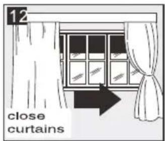
- Close the windows and doors in the room to be air conditioned (Fig. 11). When installing the appliance semi-permanently, you should leave a door slightly open (as little as 1cm ) to guarantee correct ventilation;
- Protect the room from direct exposure to the sun by partially closing curtains and/or blinds to make the appliance much more economical to run (Fig. 12);
- Never rest objects of any kind on the appliance; (Fig. 13)
- Do not block the air inlet or outlet of the appliance.
Reduced air flow will result in poor performance and could damage the unit.
- Make sure there are no heat sources in the room;
- Never use the appliance in very damp rooms (laundries for example).
- Never use the appliance outdoors.
- Make sure the appliance is standing on a level surface. if necessary, place the castor locks under the front wheels.


WATER DRAINAGE METHOD
When there is excess water condensation inside the unit, the appliance stops running and shows “ F_E ”(FULL TANK as mentioned in SELF-DIAGNOSIE). This indicates that the water condensation needs to be drained using the following procedures:
Manual Draining (fig.14)
Water may need to be drained in high humidity areas
- Unplug the unit from power source.
- Place a drain pan under the lower drain plug. See diagram.
- Remove the lower drain plug.
- Water will drain out and collect in the drain pan (maybe not supplied).
- After the water is drained, replace the lower drain plug firmly.
- Turn on the unit.
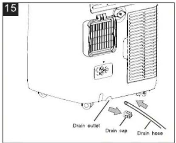
Continuous Draining (fig.15)
While using the unit in dehumidifier mode, continuous drainage is recommended.
- Unplug the unit from the power source.
- Remove the drain plug. While doing this operation some residual water may spill so please have a pan to collect the water.
- Connect the drain hose (1/2" or 12.7mm, maybe not supplied). See diagram.
- The water can be continuously drained through the hose into a floor drain or bucket.
- Turn on the unit.

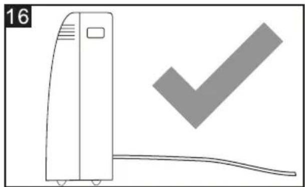
NOTE:
Please be sure that the height of and section of the drain hose should not be higher than that of the drain outlet, or the water tank may not be drained. (fig.16 and fig.17)
natural_image
Illustration of a portable air conditioner unit with a checkmark symbol (no text or labels)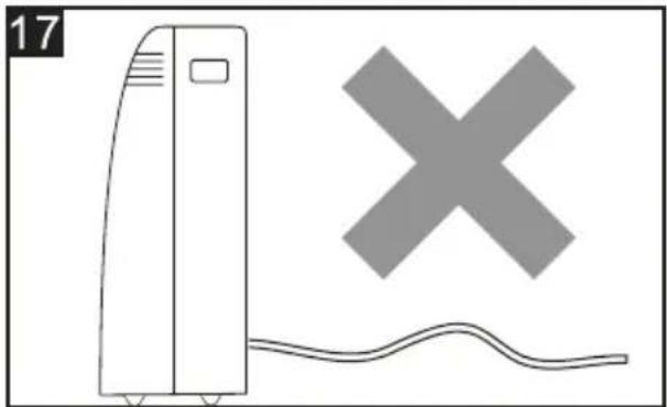
natural_image
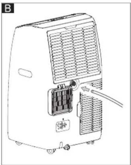
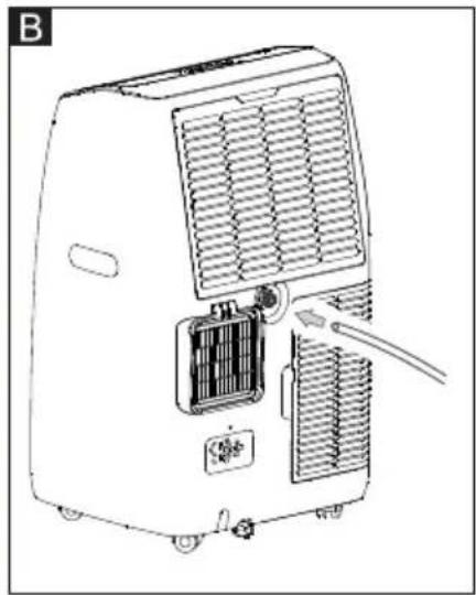
Simple line drawing of a front air conditioner unit with a cross symbol above it, no text or labels present.Middle drainage
When unit running in Dry mode, you can choose the way below to drainage.
- Unplug the unit from the power source.
- Remove the drain plug (fig A). While doing this operation some residual water may spill so please have a pan to collect the water.
- Connect the drain hose (1/2" or 12.7mm, maybe not supplied). (fig B)
- The water can be continuously drained through the hose into a floor drain or bucket.
- Turn on the unit.

natural_image
Line drawing of an air conditioner unit with cooling fins and a cable inserted (no text or symbols)
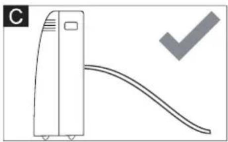
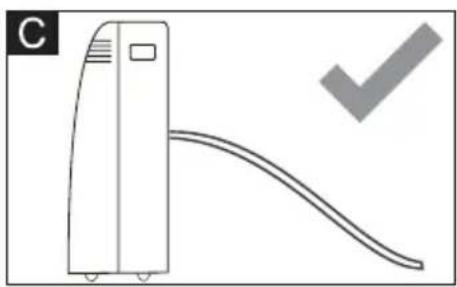
NOTE:
Please be sure that the height of and section of the drain hose should not be higher than that of the drain outlet, or the water tank may not be drained. (fig. C and fig. D)
natural_image
Simple line drawing of a vertical air conditioner unit with a curved ramp and a checkmark (no text or symbols)
natural_image
Simple line drawing of a vertical device connected to a curved cable with a cross symbol (no text or labels)CLEANING
Before cleaning or maintenance, turn the appliance off by pressing the ⏻ button on the control panel or remote control, wait for a few minutes then unplug from the mains socket.
CLEANING THE CABINET
You should clean the appliance with a slightly damp cloth then dry with a dry cloth.
- Never wash the appliance with water. It could be dangerous.
- Never use petrol, alcohol or solvents to clean the appliance.
- Never spray insecticide liquids or similar.
CLEANING THE AIR FILTERS
To keep your appliance working efficiently, you should clean the filter every week of operation.
The filter can take out like fig below.
TTo avoid possible cuts, avoid contacting the metal parts of the appliance when removing or re-installing the filter. It can result in the risk of personal injury.

natural_image
Technical line drawing of a portable air conditioner unit with cooling fins and ventilation grilles (no text or symbols)Use a vacuum cleaner to remove dust accumulations from the filter. If it is very dirty, immerse in warm water and rinse a
number of times. The water should never be hotter than 40^ C ( 104^ F). After washing, leave the filter to dry then attach the intake grille to the appliance.
START-END OF SEASON OPERATIONS
START OF SEASON CHECKS
Make sure the power cable and plug are undamaged and the earth system is efficient.
Follow the installation instructions precisely.
END OF SEASON OPERATIONS
To empty the internal circuit completely of water, remove the cap.
Run off all water left into a basin. When all the water has been drained, put the cap back in place.
Clean the filter and dry thoroughly before putting back.

natural_image
Line drawing of a portable air conditioner unit with cooling fan and ventilation grilles (no text or symbols)STRICTEST OPERATION ENVIRONMENT:
Cooling mode: 18°C-35°C (64°F-95°F), 30%RH\~90%RH
Heating mode: 10°C-25°C (50°F-77°F), 30%RH\~90%RH
| PROBLEM | CAUSE | SOLUTION |
| The appliance does not come on | There is no currentIt is not plugged into the mainsThe internal safety device has tripped | WaitPlug into the mainsWait 30 minutes, if the problem persists, contact your service center |
| The appliance works for a short time only | Here are bends in the air exhaust hoseSomething is preventing the air from being discharged | Position the air exhaust hose correctly, keeping it as short and free of curves as possible to avoid bottlenecksCheck and remove any obstacle obstructing air discharge |
| The appliance works, but does not cool the room | Windows, doors and/or curtains open | Close doors, windows and curtains, bearing in mind the "tips for correct use" given above |
| There are heat sources in the room (oven, hairdryer, etc.) | Eliminate the heat sources | |
| The air exhaust hose is detached from the appliance | Fit the air exhaust hose in the housing at the back of the appliance | |
| The technical specification of the appliance is not adequate for the room in which it is located | ||
| During operation, there is an unpleasant smell in the room | Air filter clogged | Clean the filter as described above |
| The appliance does not operate for about three minutes after restarting it | The internal compressor safety device prevents the appliance from being restarted until three minutes have elapsed since it was last turned off | Wait. This delay is part of normal operation |
| The following message appears on the display:PF / FE | The appliance has a self-diagnosis system to identify a number of malfunctions | See the SELF-DIAGNOSIS Chapter |
PŘÍRUČKA UŽIVATELE
PŘENOSNÁ KLIMATIZACE

natural_image
Line drawing of a portable air purifier with wheels and control panel (no text or symbols)natural_image
Symbol of a trash bin crossed with a diagonal line, no text or numbers presentnatural_image
Diagram of a cylindrical object with a curved opening and labeled 'Obr.3' (no text or symbols on the object itself)

natural_image
Diagram showing a device connected to a pipe with a diagonal line crossing through it (no text or symbols present)natural_image
Simple diagram with two horizontal black lines inside a rectangle (no text or symbols)natural_image
Three abstract geometric shapes with black fill patterns, no text or symbols presentDRY mód
flowchart
graph LR
    A["3D Object"] --> B["3D Dashed Arrow"]
    B --> C["3D Box with Arrow"]
    C --> D["3D Box with Arrow"]
    D --> E["3D Box with Arrow"]
Výměna baterií
natural_image
Diagram of a handheld electronic device with a USB port and cable, showing internal components and a close-up of the cable (no text or symbols present)PŘEPNUTÍ JEDNOTKY TEPLOTY
REŽIM SMART (chytrý)
flowchart
graph LR
    A["Rectangular Frame"] --> B["Dashed Rectangle with Arrow"]
    B --> C["Rectangular Frame with Arrow"]
    C --> D["Dashed Rectangle with Arrow"]
    D --> E["Rectangular Frame with Arrow"]
    E --> F["Rectangular Frame with Arrow"]
Blikání:
REŽIM SLEEP (spánek)
REŽIM ČASOVAČE ---- VYPNOUT ČASOVAČ
Poznámka:
natural_image
Illustration of a vertical air conditioner unit next to a checkmark symbol (no text or labels)
natural_image
Simple line drawing of a front air conditioner unit with a cross symbol above it, and a wavy line below (no text or labels)Střední odvodnění
natural_image
Line drawing of an air conditioner unit with cooling fins and a cable inserted (no text or symbols)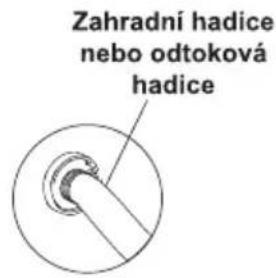
natural_image
Diagram of a vertical air conditioner unit with a curved duct and a checkmark (no text or symbols)
natural_image
Simple line drawing of a vertical device with a curved line and a cross symbol, no text or labels present.natural_image
Technical line drawing of a portable air conditioner unit with cooling fins and ventilation grilles (no text or symbols)natural_image
Diagram of a refrigerant unit with heat exchanger and cooling unit (no text or symbols)NEJPŘÍSNĚJŠÍ PROVOZNÍ PROSTŘEDÍ:
Chladicí režim: 18 °C - 35 °C (64 °F - 95 °F), 30 % RH \~ 90 % RH
Režim topení: 10°C-25°C (50°F-77°F), 30%RH\~90%RH
natural_image
Line drawing of a portable air purifier with wheels and control panel (no text or symbols)natural_image
Symbol of a trash bin crossed with a diagonal line, no text or numbers presentnatural_image
Diagram showing a cylindrical object with a curved arrow pointing to it, labeled 'Afb.3' (no text or symbols on the diagram itself)
natural_image
Diagram showing a device connected to a curved pipe with a diagonal line crossing through it (no text or symbols present)HET APPARAAT INSCHAKELEN
natural_image
Simple diagram with two horizontal black lines inside a rectangle (no text or symbols)COOL (KOEL)modus
natural_image
Three abstract geometric shapes with varying fill patterns: three squares, one square, and one rectangle (no text or symbols)DRY (DROOG) modus
natural_image
Diagram of a handheld device with an arrow indicating rotation or movement, no text or symbols presentflowchart
graph LR
    A["Square with arrow"] --> B["Square with dashed arrow"]
    B --> C["Square with dashed arrow and arrow"]
    C --> D["Circular shape with arrow and dashed arrow"]
Knipperen:
| Laag | Medium | Hoog | Auto |
 (FLITS) (FLITS) |
(FLITS)
LUCHTSTROOMREGELING
Opmerking:
MRTHODE VAN WATERAFVOER
Handmatig aftappen (afb.14)
natural_image
Illustration of a vertical air conditioner unit next to a checkmark symbol (no text or labels)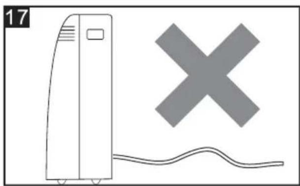
natural_image
Illustration of a portable air conditioner next to a cross symbol and wavy line, with no visible text or symbols.Middelste waterafvoer
natural_image
Line drawing of an air conditioner unit with cooling fan and attached plug (no text or symbols)
OPMERKING:
natural_image
Line drawing of a vertical air conditioner unit with a curved ramp and a checkmark (no text or symbols)
natural_image
Simple line drawing of a server unit connected to a cable with a cross symbol (no text or labels)natural_image
Technical line drawing of a portable air conditioner unit with cooling fins and ventilation grilles (no text or symbols)natural_image
Diagram of a mechanical or electrical component with no visible text, numbers, or symbolsSTRIKTSTE WERKOMGEVING:
Koelmodus: 18 °C-35 °C (64 °F-95 °F), 30% RH \~ 90% RH
Verwarmingsmodus: 10°C-25°C (50°F-77°F), 30%RH\~90%RH
natural_image
Line drawing of a portable air purifier with wheels and control panel (no text or symbols)natural_image
Symbol of a trash bin crossed with a diagonal line, no text or numbers presentnatural_image
Diagram showing a cylindrical object with a curved arrow indicating rotation, labeled Fig. 2 (no text or symbols on the diagram itself)
natural_image
Diagram of a cylindrical object with a curved top and arrow indicating rotation, labeled Fig. 3 (no text or symbols on the diagram itself)
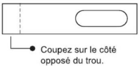
natural_image
Diagram showing a device connected to a pipe with a diagonal line crossing through it (no text or symbols present)natural_image
Simple diagram with two horizontal double-headed arrows inside a rectangle (no text or symbols)Mode HEAT (Chauffage)
natural_image
Three abstract geometric shapes with varying fill patterns: three squares, one square, and one rectangle (no text or symbols)flowchart
graph LR
    A["Step 1: Solid rectangle with dashed arrow"] --> B["Step 2: Dashed rectangle with solid arrow"]
    B --> C["Step 3: Dashed rectangle with solid arrow"]
    C --> D["Step 4: Solid rectangle with dashed arrow"]
natural_image
Diagram of a handheld device with a scroll and cable, showing internal components and a close-up of the cable (no text or symbols)MODE SMART (Intelligent)
flowchart
graph LR
    A["Square with arrow"] --> B["Dashed rectangle with arrow"]
    B --> C["Square with arrow and arrow"]
    C --> D["Dashed rectangle with arrow and arrow"]
    D --> E["Square with arrow and arrow"]
Clignotant :
Nota :
natural_image
Simple line drawing of a vertical air conditioner unit with a checkmark symbol (no text or labels)
natural_image
Illustration of a front-loading air conditioner unit with a large 'X' symbol and wavy base (no text or labels)Drainage moyen
natural_image
Line drawing of an air conditioner unit with cooling fan and attached plug (no text or symbols)
natural_image
Diagram of a vertical air conditioner unit with a curved ramp and a checkmark (no text or symbols)
natural_image
Simple line drawing of a server unit connected to a curved cable with a cross symbol (no text or labels)natural_image
Diagram of a vehicle's front panel showing the grille, air vent, and exhaust pipe (no text or symbols)ENVIRONNEMENT DE FONCTIONNEMENT LE PLUS STRICT :
Mode Cooling (Refroidissement) : 18 °C-35 °C (64 °F-95 °F), 30 % RH \~ 90 % RH
Mode Heating (Chauffage): 10 °C-25 °C (50 °F-77 °F), 30 % RH \~ 90 % RH
natural_image
Line drawing of a portable air purifier with wheels and control panel (no text or symbols)natural_image
Symbol of a trash bin crossed with a diagonal line, no text or numbers presentZUBEHÖR
natural_image
Diagram showing a cylindrical object with a circular opening and a curved arrow indicating rotation (no text or symbols)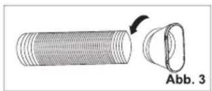
natural_image
Diagram of a cylindrical object with a curved arrow indicating rotation, labeled 'Abb. 3' (no text or symbols on the object itself)
natural_image
Diagram showing a device connected to a pipe with a crossed line indicating no crossing or disconnection (no text or symbols present)natural_image
Simple diagram with two horizontal black lines inside a rectangle (no text or symbols)KÜHL-Modus
natural_image
Pure geometric pattern of six black shapes arranged in a 2x2 grid (no text or symbols)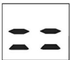
natural_image
Four black geometric shapes arranged in a 2x2 grid on white background (no text or symbols)
natural_image
Two black geometric shapes on a white background, no text or symbols presentTROCKEN-Modus
flowchart
graph LR
    A["3D Grid with directional arrows"] --> B["3D State with dashed arrow"]
    B --> C["3D State with solid arrow"]
    C --> D["3D State with dashed arrow"]
    D --> E["3D State with solid arrow"]
natural_image
Diagram of a handheld electronic device with a scroll and control buttons, showing internal components and directional arrows (no text or symbols)UMSCHALTEN DER TEMPERATUREINHEIT
HEIZEN-MODUS
flowchart
graph LR
    A["Square with arrow"] --> B["Dashed rectangle with arrow"]
    B --> C["Square with arrow"]
    C --> D["Dashed rectangle with arrow"]
    D --> E["Square with arrow"]
Blinkt:
LED-Displaybeleuchtung EIN/AUS (optional)
Hinweis:
natural_image
Simple line drawing of a vertical air conditioner unit with a checkmark symbol (no text or labels)
natural_image
Illustration of a front air conditioner unit and a cross symbol with wavy base (no text or labels)
natural_image
Line drawing of an air conditioner unit with cooling fan and ventilation slots (no text or symbols)natural_image
Simple line drawing of a vertical air conditioner unit with a curved ramp and a checkmark (no text or symbols)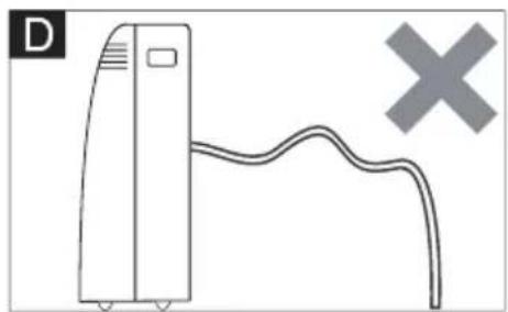
natural_image
Simple line drawing of a vertical air conditioner unit connected to a curved cable with a cross symbol (no text or labels)natural_image
Technical line drawing of a portable air conditioner unit with cooling fins and ventilation grilles (no text or symbols)natural_image
Diagram of a vehicle's front panel showing the grille, air vent, and exhaust pipe (no text or symbols)natural_image
Line drawing of a portable air purifier with wheels and top cover (no text or symbols)natural_image
Symbol of a trash bin crossed with a diagonal line, no text or numbers presentnatural_image
Diagram showing a cylindrical object with a curved arrow indicating rotation, labeled Fig.2 (no text or symbols on the object itself)
natural_image
Diagram of a cylindrical object with a separate curved component, labeled Fig.3 (no text or symbols on the object itself)

natural_image
Diagram showing a device connected to a curved pipe with a diagonal line crossing through it (no text or symbols present)natural_image
Simple diagram with two horizontal black lines inside a rectangle (no text or symbols)natural_image
Three abstract geometric shapes with black fill patterns, no text or symbols presentflowchart
graph LR
    A["3D Grid with directional arrows"] --> B["3D State with dashed arrow"]
    B --> C["3D State with dashed arrow and left-pointing arrow"]
    C --> D["3D State with dashed arrow and right-pointing arrow"]
DISPLAY del telecomando, significa i simboli sul display a cristalli liquidi
natural_image
Diagram of a handheld device with a USB port and cable, showing internal components and a close-up view (no text or symbols)CAMBIARE L'UNITÀ DI TEMPERATURA
MODALITÀ SMART (INTELLIGENTE)
flowchart
graph LR
    A["Square with arrow"] --> B["Square with dashed arrow"]
    B --> C["Square with dashed arrow"]
    C --> D["Square with arrow"]
    D --> E["Square with dashed arrow"]
MODALITÀ SLEEP (DORMIRE)
Nota:
natural_image
Illustration of a vertical air conditioner unit next to a checkmark symbol (no text or labels)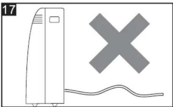
natural_image
Illustration of a refrigerant unit with a cross symbol and wavy line below (no text or labels)Drenaggio centrale
natural_image
Line drawing of an air conditioner unit with ventilation grilles and a cable inserted (no text or symbols)
natural_image
Simple line drawing of a vertical air conditioner unit with a curved ramp and a checkmark (no text or symbols)
natural_image
Simple line drawing of a server unit with a curved cable and a cross symbol (no text or labels)natural_image
Technical line drawing of an air conditioning unit with cooling fins and a side panel (no text or symbols)natural_image
Diagram of a mechanical or electrical component with no visible text, numbers, or symbolsnatural_image
Line drawing of a portable air purifier with wheels and top cover (no text or symbols)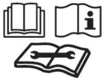
natural_image
Three black-and-white icons: open book, open book with 'i' symbol, and open notebook with wrench (no text or symbols)natural_image
Symbol of a trash bin crossed with a diagonal line, no text or numbers presentnatural_image
Diagram showing a cylindrical object with a circular opening and a curved arrow indicating rotation (no text or symbols)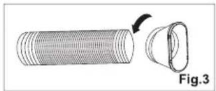
natural_image
Diagram of a cylindrical object with a curved top and arrow indicating rotation, labeled Fig.3 (no text or symbols on the object itself)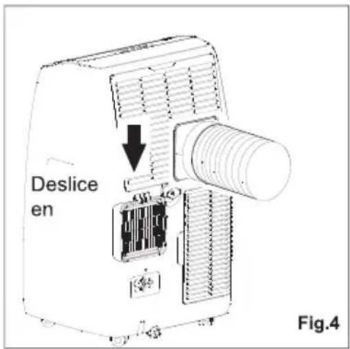

natural_image
Diagram showing a device connected to a pipe with a crossed line indicating no crossing or disconnection (no text or symbols present)natural_image
Simple diagram with two horizontal black lines inside a rectangle (no text or symbols)natural_image
Three abstract geometric shapes with varying fill patterns: three squares, one centered with four diamond shapes, the other two arranged in a grid (no text or symbols)Modo DRY (SECADO)
Botones del control remoto
natural_image
Diagram of a handheld device with a scroll wheel and cable, showing internal components and a control panel (no text or symbols)Flashing:
| Baja | Media | Alta | Automática |
 (FLASH) (FLASH) |
(FLASH)
CONTROL DE FLUJO DE AIRE
Nota:
natural_image
Illustration of a vertical air conditioner unit with a checkmark symbol (no text or labels)
natural_image
Illustration of a portable air conditioner next to a cross symbol and wavy line, with no visible text or symbols.Drenaje medio
natural_image
Line drawing of an air conditioner unit with cooling fan and attached plug (no text or symbols)
natural_image
Simple line drawing of a vertical air conditioner unit with a curved ramp and a checkmark (no text or symbols)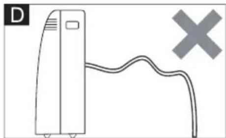
natural_image
Simple line drawing of a vertical device with a curved cable and a cross symbol (no text or labels)natural_image
Technical line drawing of a portable air conditioner unit with cooling fins and ventilation grilles (no text or symbols)natural_image
Diagram of a refrigerant unit with heat exchanger and cooling unit (no text or symbols)

- Prema IEC standardu:
- Posebne informacije u vezi s aparatima s rashladnim plinom R290
- ISPUST VRUĆEG ZRAKA
- POSTAVLJANJE KOMPLETA KLIZAČA PROZORA
- Način COOL (HLAĐENJA)
- Način DRY (SUHI)
- Način SMART (PAMETAN)
- PREBACITE JEDINICU TEMPERATURE
- NAČIN COOLING (HLAĐENJA)
- NAČIN HEATING (GRIJANJA)
- PROTOK ZRAKA
- NAČIN TIMER (TAJMER) – PRIMENITI ZA TIMER ON (UKLJUČITE TAJMER)
- Turbo funkcija (po izboru)
- BILJEŠKA:
- Srednja odvodnja
- POČETAK SEZONSKIH PROVJERA
- STROGO RADNO OKRUŽENJE:
- IMPORTANT SAFEGUARDS
- According the EN standard:
- According the IEC standard:
- Specific information regarding appliances with R290 refrigerant gas
- Removal and evacuation (Annex DD.9)
- Charging procedures (Annex DD.10)
- Decommissioning (Annex DD.11)
- Competence of service personnel General
- SOME NOTIONS ON HUMIDITY
- ELECTRICAL CONNECTIONS
- EXHAUSTING HOT AIR
- WINDOW SLIDER KIT INSTALLATION
- LOCATION
- DESCRIPTION OF THE DISPLAY SCREEN
- TURNING THE APPLIANCE ON
- COOL mode
- HEAT mode \*
- NOTE:
- FAN mode
- DRY mode
- SMART mode
- SETTING THE TIMER
- Programming start up
- Programming shut down
- Switch the unit of temperature
- Wi-fi function
- SELF-DIAGNOSIS
- Remote controller DISPLAY, meaning of symbols on the liquid crystal display
- REMOTE CONTROL MANUAL
- Replacement of Batteries
- TURN ON / TURN OFF THE AIR CONDITIONER
- COOLING MODE
- HEATING MODE
- FAN MODE(Not FAN button)
- AIR FLOW CONTROL
- SLEEP MODE
- TIMER MODE----SET TIMER OFF
- TIMER MODE----SET TIMER ON
- Turbo function (Optional)
- ECO MODE (Optional) (No available for this model)
- LED display light ON/OFF (Optional)
- (No available for this model)
- HEALTH function (Optional)
- TIPS FOR CORRECT USE
- WATER DRAINAGE METHOD
- Manual Draining (fig.14)
- Continuous Draining (fig.15)
- Middle drainage
- CLEANING
- CLEANING THE CABINET
- CLEANING THE AIR FILTERS
- START-END OF SEASON OPERATIONS
- START OF SEASON CHECKS
- END OF SEASON OPERATIONS
- STRICTEST OPERATION ENVIRONMENT:
- PŘÍRUČKA UŽIVATELE
- PŘENOSNÁ KLIMATIZACE
- DRY mód
- Výměna baterií
- PŘEPNUTÍ JEDNOTKY TEPLOTY
- REŽIM SMART (chytrý)
- REŽIM SLEEP (spánek)
- REŽIM ČASOVAČE ---- VYPNOUT ČASOVAČ
- Poznámka:
- Střední odvodnění
- NEJPŘÍSNĚJŠÍ PROVOZNÍ PROSTŘEDÍ:
- HET APPARAAT INSCHAKELEN
- COOL (KOEL)modus
- DRY (DROOG) modus
- LUCHTSTROOMREGELING
- Opmerking:
- MRTHODE VAN WATERAFVOER
- Handmatig aftappen (afb.14)
- Middelste waterafvoer
- STRIKTSTE WERKOMGEVING:
- Mode HEAT (Chauffage)
- MODE SMART (Intelligent)
- Nota :
- Drainage moyen
- ENVIRONNEMENT DE FONCTIONNEMENT LE PLUS STRICT :
- KÜHL-Modus
- TROCKEN-Modus
- UMSCHALTEN DER TEMPERATUREINHEIT
- HEIZEN-MODUS
- LED-Displaybeleuchtung EIN/AUS (optional)
- Hinweis:
- CAMBIARE L'UNITÀ DI TEMPERATURA
- MODALITÀ SMART (INTELLIGENTE)
- MODALITÀ SLEEP (DORMIRE)
- Nota:
- Drenaggio centrale
- Modo DRY (SECADO)
- CONTROL DE FLUJO DE AIRE
- Drenaje medio
Brand : TCL
Model : TAC-12CHB/NZW
Category : Air purifier