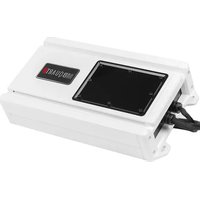
NA3-750.1 - Receiver MB QUART - Free user manual and instructions
Find the device manual for free NA3-750.1 MB QUART in PDF.


| Product Type | Car Audio Mono Amplifier |
| Model | NA3-750.1 |
| Brand | MB Quart |
| Power Output (RMS) | 750W x 1 @ 1 Ohm; 450W x 1 @ 2 Ohm; 250W x 1 @ 4 Ohm |
| Peak Power | 1500W |
| Frequency Response | 10 Hz - 250 Hz |
| Signal-to-Noise Ratio | > 90 dB |
| Input Sensitivity | 0.2V - 6V |
| Low Pass Filter | Variable 40 Hz - 250 Hz |
| Subsonic Filter | Fixed 15 Hz |
| Bass Boost | 0 - 12 dB @ 45 Hz |
| Inputs | RCA Line Input |
| Speaker Outputs | Positive and Negative Binding Posts |
| Power Supply | 2 x 50A External Fuse (Recommended) |
| Dimensions (L x W x H) | 15.0 x 7.5 x 2.0 inches (381 x 191 x 51 mm) |
| Weight | 5.5 lbs (2.5 kg) |
| Protection Features | Thermal, Overload, Short Circuit |
| Mounting | Standard Chassis Mounting |
| Color | Black with Chrome MB Quart Badge |
| Maintenance | Clean with dry cloth; ensure proper ventilation |
| Spare Parts Availability | Contact MB Quart customer service |
| Manual Language | English (PDF download) |
Frequently Asked Questions - NA3-750.1 MB QUART
User questions about NA3-750.1 MB QUART
0 question about this device. Answer the ones you know or ask your own.
Ask a new question about this device
Download the instructions for your Receiver in PDF format for free! Find your manual NA3-750.1 - MB QUART and take your electronic device back in hand. On this page are published all the documents necessary for the use of your device. NA3-750.1 by MB QUART.
USER MANUAL NA3-750.1 MB QUART
natural_image
Red triangular warning sign with exclamation mark on yellow background (no text or symbols beyond the icon itself)PLEASE NOTE:
If switch is set to DC sense on, the amplifier will not turn on via the amplifiers remote turn on wire. So if the amplifier will not turn on please view this switch on the control panel and adjust accordingly.
For more information visit our website.

PLEASE NOTE:
The MB Quart logo panel can be mounted in either direction depending on your installation configuration. After the amplifier is mounted in its final position, remove the adhesivebacking and affix to the amplifier in the desired position pressing down for 10 seconds.
For more information visit our website.
MBQUART® MUSIC. DEFINED.
Quick Start Installation Guide
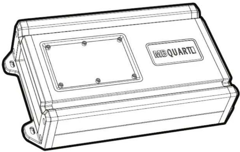
natural_image
Technical line drawing of a rectangular electronic enclosure with mounting holes and a square recess (no text or symbols)NA3-560.4
NA3-1000.5
NA3-600.6
NA3-750.1
Before you start

CAUTION

Many new and factory radios require a reset code when disconnected from battery power. This is an anti-theft feature. Before unplugging power, you must determine if your radio/source unit requires a reset code. Check the operation manual for your vehicle or contact the dealer.
Congratulations on your choice of a MBQuart amplifier. This "Quick Start Installation" guide is meant to help you "hook up" and play music. For more detailed information, on system setting, speaker and subwoofer configuration and full specifications by model please visit our website at www.MBQuart.com
Power cable size
It is critical to use the proper power and ground cable. Select the size listed here for your amplifier model. Always use high quality copper cable. Visit our website for multi amp system cable recommendations.
Model
Cable Size
NA3-560.4
NA3-1000.5
NA3-600.6
NA3-750.1
10ga
Installation
1 Disconnect Negative Battery Terminal
Place terminal in a secure position so that it won't accidentally contact the negative battery post

natural_image
Line drawing of a battery with two plates and a terminal connector (no text or symbols)2 Run Cables
Properly route power, speaker and RCA cables through the vehicle.
3 Mount Amplifier
Choose a mounting location that will provide adequate air ventilation. Mount the amplifier to a secure surface. Do not mount the amplifier upside down.


Ground

The ground connection is critical to the performance of the amplifier. Choose a location that is close to the amplifier. Completely scrape away the paint and use a nut and bolt if possible. DO NOT USE AN EXISTING FACTORY BOLT!


Power Connection
Attach the chassis ground, +12V and amp turn on wire. It is important to make sure these connections are very secure.
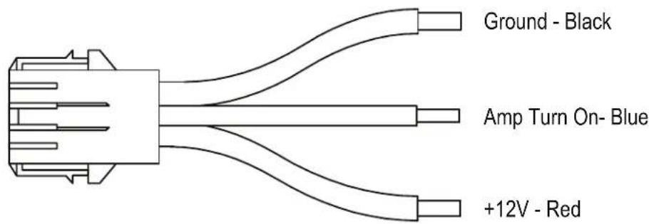
REM TURN ON / DC SENSE ON SWITCH
There are two methods of switching the amplifier on and off. Select the appropriate position suited for your application.
REM TURN ON This will turn on the amplifier when a +12v switched power typically from a source unit, is connected to the Amp Turn On - BLUE wire on the main power connection harness. DC SENSE The DC SENSE is for use with source units that do not offer RCA outputs.

PLEASE NOTE: If switch is set to DC sense on, the amplifier will not turn on via the amplifiers remote turn on wire. So if amplifier will not turn on please view this switch on the top control panel and adjust accordingly. For more information on DC Sense and wiring visit MBQUART.com

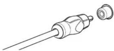
Signal Input Connection
Connect the RCA cables to the INPUT connectors. PLEASE NOTE: If using RCA connectors, the colors coinside with speaker wire color.
natural_image
Line drawing of a medical or laboratory device with a bulb and connector (no text or symbols)
Gain Control

Turn the GAIN control completely counter-clockwise to minimum.

8
Speaker Connections
Connect the speaker cables to the speaker output connectors. Follow the diagram below that best fits your speaker configuration.

natural_image
Pure electrical connector diagram without any text, numbers, or symbolsCH1 Positive - White
CH1 Negative - White / Black
CH2 Positive - Gray
CH2 Negative - Gray / Black
CH3 Positive - Green
CH3 Negative - Green / Black
CH4 Positive - Purple
CH4 Negative - Purple / Black
NA3-560.4
natural_image
Pure electrical connector diagram without any text, numbers, or symbolsCH1 Positive - White
CH1 Negative - White / Black
CH2 Positive - Gray
CH2 Negative - Gray / Black
CH3 Positive - Green
CH3 Negative - Green / Black
CHA Positive - Purple
CH4 Negative - Purple / Black
CH5 Positive - Brown
CH5 Negative - Brown/ Black
NA3-1000.5

natural_image
Pure electrical circuit lines without any symbolsCH1 Positive - White
CH1 Negative - White / Black
CH2 Positive - Gray
CH2 Negative - Gray / Black
CH3 Positive - Green
CH3 Negative - Green / Black
CH4 Positive - Purple
CH4 Negative - Purple / Black
CH5 Positive - Brown
CH5 Negative - Brown / Black
CH6 Positive - Pink
CH6 Negative - Pink/ Black
NA3-600.6

Positive - Brown
Positive - Brown
Negative - Brown / Black
Negative - Brown / Black
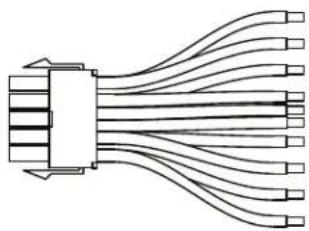
NA3-750.1
PLEASE NOTE: If using one subwoofer, please connect all wires. If using two subwoofers, please still connect all wires.
9
Positive Battery Connection
Connect the power cable to the positive battery terminal. The power cable must be fused within 18 inches of the battery terminal.

natural_image
Line drawing of a battery with two leads and a terminal block (no text or symbols)
Be prepared to disarm your vehicle's alarm and to enter your radio / source unit code.

10
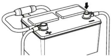
Re-connect Negative Battery Terminal
Re-connect the negative battery terminal making sure it is securely tightened.
natural_image
Line drawing of a battery with two plates and connected tubing (no text or symbols)Setup

Open Control Panel
To gain access to the NA3 amplifier series top mount setting control panel carefully remove the six screws and lift the face plate up.
When you're finished with the control panel mindfully put the face plate back together with the six screws. Make sure not to over tighten.

natural_image
Line drawing of a rectangular electronic device with a lid and indicator lights above it (no text or symbols)
Settings
The illustrations below describe the various controls. Refer to the illustration that matches your amplifier.
① LEVEL Adjustment
The level control purpose is to match the output of your source signal to the amplifier. Refer to the section C for detailed instructions.
② X-OVER Switch
This switch will set the amplifier to have a full frequency output or to filter out high or low frequencies.
③ Frequencies Adjustment
The Low Pass Filter will cut off the frequencies above the setting. The High Pass Filter will cut off the frequencies below the setting.
④ SUBSONIC Switch
The Subsonic Switch will cut off the frequencies below the setting.
⑤ BASS BOOST

The Bass EQ control will increase the power output at 45Hz for more pronounced bass. Exercise caution when using this control. Increase the level in small amounts until distortion is noticed, then back off a little.
NA3-560.4

NA3-1000.5

NA3-750.1
NA3-600.6


Level Setting

This is a critical step to insure your amplifier is properly adjusted to match the signal output level of your source unit.
THIS IS NOT A VOLUME CONTROL!

MINMAX
- If possible, with the source unit off, confirm that the primary volume control is turned down (counter clockwise).
- Turn on the source unit (CD, or MP3 player). Re-confirm that the volume is turned down. Make sure the source unit controls; balance, fader, bass and treble are all set to center or "0" adjustment. Make sure that the green LED on the end of the amplifier is illuminated.
- Play a clean musical selection of which you are very familiar. CD is preferred. Do not use radio signals for level setting. Hit play and start turning the volume of the source unit up.
- Stop increasing the source unit volume when you reach 3/4 (about 75%) or until you hear speakers begin to slightly start producing distortion.
- Increase the amplifier gain (clockwise) until distortion is heard, then back the level down (counter clockwise) until the distortion is eliminated. Small adjustments may need to be made to balance the levels of multiple amplifiers.

Remote Level Control
Some models include a bass remote. Avoid adjusting the bass remote while operating vehicle.

natural_image
Diagram of a remote network connection showing a switch and connector (no text or symbols)


MBQuart.com
#MUSIC DEFINED
WARRANTY
Maxxsonics USA Inc. warrants this product, to the original consumer purchaser, to be free from defects in material and workmanship for a period of one (1) year from the date of purchase. Maxxsonics USA Inc. will, at its discretion, repair or replace defective products during the warranty period. Components that prove to be defective in materials and workmanship under proper installation and use must be returned to the original authorized Maxxsonics USA Inc. retailer from where it was purchased. A photocopy of the original receipt must accompany the product being returned. The costs associated with removal, re-installation and freight are not the responsibility of Maxxsonics USA Inc. This warranty is limited to defective parts and specifically excludes consequential damages connected therewith. To view the full warranty, please visit the website.
any incidental or
MBQuart products are designed and engineered in the USA by
MAXXSONICS®
- PLEASE NOTE:
- MBQUART® MUSIC. DEFINED.
- Quick Start Installation Guide
- Before you start
- CAUTION
- Power cable size
- Installation
- Disconnect Negative Battery Terminal
- Run Cables
- Mount Amplifier
- Ground
- Power Connection
- REM TURN ON / DC SENSE ON SWITCH
- Signal Input Connection
- Gain Control
- 8
- Speaker Connections
- 9
- Positive Battery Connection
- 10
- Re-connect Negative Battery Terminal
- Setup
- Open Control Panel
- Settings
- Level Setting
- THIS IS NOT A VOLUME CONTROL!
- Remote Level Control
- MBQuart.com
- #MUSIC DEFINED
- WARRANTY
Brand : MB QUART
Model : NA3-750.1
Category : Receiver