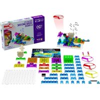
Circuit 120 - Models E-Blox - Free user manual and instructions
Find the device manual for free Circuit 120 E-Blox in PDF.


| Product Type | Electronic Building Kit |
| Model | Circuit 120 |
| Brand | E-Blox |
| Category | Building Sets (Maquettes) |
| Number of Pieces | 120 |
| Recommended Age | 8+ years |
| Power Source | 3 x AA batteries (not included) |
| Dimensions (Box) | 13.0 x 9.0 x 2.5 inches |
| Weight | 2.0 lbs |
| Main Functions | Build various circuits, learn electronics, create magnetic and sound effects |
| Includes | Building blocks, LED modules, sound module, motor, wires, connectors |
| Safety Warnings | Not for children under 3 years; small parts hazard; adult supervision recommended |
| Cleaning | Wipe with dry cloth; keep away from water |
| Spare Parts | Available via manufacturer website or authorized dealers |
| Repairability | Modular design; individual components can be replaced |
| Warranty | 1 year limited warranty against defects |
| Certifications | CE, RoHS, ASTM |
Frequently Asked Questions - Circuit 120 E-Blox
User questions about Circuit 120 E-Blox
0 question about this device. Answer the ones you know or ask your own.
Ask a new question about this device
Download the instructions for your Models in PDF format for free! Find your manual Circuit 120 - E-Blox and take your electronic device back in hand. On this page are published all the documents necessary for the use of your device. Circuit 120 by E-Blox.
USER MANUAL Circuit 120 E-Blox
natural_image
Colorful LEGO building blocks with green and yellow plastic components, no visible text or symbols
TM


WARNING: SHOCK HAZARD
Never connect E-Blox® Circuit Blox™ to the electrical outlets in your home in any way!

WARNING:
Only use the battery holder with the cover securely in place.

WARNING: CHOKING HAZARD
Small parts. Not for children under 3 years.

WARNING: MOVING PARTS
Do not touch the fan while it is spinning.
CIRCUIT BLOX™ 120
WARNING: Always check your wiring before turning on a circuit. Never leave a circuit unattended while the batteries are installed. Never connect additional batteries or any other power sources to your circuits. Discard any cracked or broken parts.
Adult Supervision:
Because children's abilities vary so much, even with age groups, adults should exercise discretion as to which experiments are suitable and safe (the instructions should enable supervising adults to establish the experiment's suitability for the child). Make sure your child reads and follows all of the relevant instructions and safety procedures, and keeps them at hand for reference.
This product is intended for use by adults and children who have attained sufficient maturity to read and follow directions and warnings.
Never modify your parts, as doing so may disable important safety features in them, and could put your child at risk of injury.
FCC Notice: Please note that changes or modifications not expressly approved by the party responsible for compliance could void the user's authority to operate the equipment.
NOTE: This equipment has been tested and found to comply with the limits for a Class B digital device, pursuant to Part 15 of the FCC Rules. These limits are designed to provide reasonable protection against harmful interference in a residential installation. This equipment generates, uses and can radiate radio frequency energy and, if not installed and used in accordance with the instructions, may cause harmful interference to radio communications. However, there is no guarantee that interference will not occur in a particular installation. If this equipment does cause harmful interference to radio or television reception, which can be determined by turning the equipment off and on, the user is encouraged to try to correct the interference by one or more of the following measures: • Reorient or relocate the receiving antenna. • Increase the separation between the equipment and receiver. • Connect the equipment into an outlet on a circuit different from that to which the receiver is connected. • Consult the dealer or an experienced radio/TV technician for help.

Batteries:
- Use only 1.5V "AA" type, alkaline batteries (not included).
- Insert batteries with correct polarity.
● Non-rechargeable batteries should not be recharged. - Rechargeable batteries should only be charged under adult supervision, and should not be recharged while in the product.
-
Do not mix old and new batteries.
-
Do not mix alkaline, standard (carbon-zinc), or rechargeable (nickel-cadmium) batteries.
- Remove batteries when they are used up.
- Do not short circuit the battery terminals.
- Never throw batteries in a fire or attempt to open its outer casing.
● Batteries are harmful if swallowed, so keep away from small children.
Basic Troubleshooting
- Most circuit problems are due to incorrect assembly, always double-check that your circuit exactly matches the drawing for it.
- Be sure that parts with positive/negative markings are positioned as per the drawing.
- Be sure that all connections are securely made.
- Try replacing the batteries. Note: Rechargeable batteries do not work as well as alkaline batteries.
E-Blox ^® is not responsible for parts damaged due to incorrect wiring.
Note: If you suspect you have damaged parts, you can follow the Advanced Troubleshooting procedure on page 15 to help determine which ones need replacing.
About Electricity (Science)
1. What is Science?

Q: What do we mean when we say "Science"?

A: Science is defined as the intellectual and practical activity encompassing the systematic study of the structure and behavior of the physical and natural world through observation and experiment.
Early scientists were curious people that wondered what made lightning. They decided to experiment to see if they could understand lightning and even make their own somehow.

natural_image
Circular blue-toned image showing a white river network with branching water channels, resembling a river or sea current (no text or symbols)3. What Other Ways Does Science Help Us?

Q: What are some areas of Science?

A: A few major Sciences are Biology, Chemistry, Astronomy, and Physics.
Biology is the study of living things like plants & animals.
Chemistry is the study of substances & how th react when you combine them. Things like the plastic in your remote and the batteries that make it work.
Astronomy is the study of the universe.
Physics is the study of matter, energy, and forces that are on structures like a tall tower.
The science of Electronics is considered a branch of Physics.

2. Who Discovered Electricity?

Q: Who was the first scientist to study electricity?

A: In ancient Greece, it was found that rubbing fur on amber produced an attraction between the two. This discovery is cited to the philosopher Thales of Miletus. One day, when was polishing his amber at home, he found that a piece fur was attracted by the amber after he put it on the desk.
Then he split them, but it happened again. So he made a record about the phenomenon. It took many centuries before anyone was able to connect this phenomenon with electricity and a century before electrical current was put to practical use.

4. Can Science Help Predict the Weather?

Q: What Sciences were used to help weather prediction?

A: Putting a satellite into orbit that could monitor the weather required the use of almost all the Sciences.
Astronomy and Physics were needed to forces of gravity and how objects stay in orbit.
Chemistry was needed to make materials that could withstand the heat and cold and to make fuels to get the satellite into orbit. Electronics was used to study the weather and transmit it back to earth. Biology was needed to study how repair people could work in orbit.

About Electricity (Technology)
5. What is Technology?

Q: What is technology and who used technology in the past?

A: Technology is the application of scientific knowledge for practical purposes. Dating back to the 18th century, Benjamin Franklin (a famous American) proved that lightning was caused by electricity by performing an experiment in which an electrical conductor would be used to extract power from a thundercloud. In the experiment, he flew a kite with a metal key attached to it into a suitable cloud. The precise historical details are unclear, but he may have then retrieved the key and discharged electricity from it. He later, in 1799, invented the lightning rod, a device that served a practical purpose.

7. Technology in Everyday Life

Q: Where do we see Technology?

A: Since Technology is the application of scientific knowledge, we see it every day when we watch television, cook in an electric pot, ride on a train that is powered by electricity, and more. Repairmen that fix our furnaces or our air-conditioning units are technicians because knowledge of how the science was used to make things hot and cold helps us repair a broken device.

natural_image
Illustration of a modern tram with a monitor and a cooking pot nearby (no text or symbols)6. Technical Terms

Q: What terms do electrical technicians need to know?

A: When technicians work on circuits and appliances there are some terms they need to know. Current is the ment of electrons and is measured in Amperes (Amps), is named in honor of André-Marie Ampère. Resistance the opposition of the flow of electric current and is
measured in Ohms, which is named after George Ohm. Electro-Motive Force EMF that pushes the electrons through the resistance is measured in Volts, named after Alessandro Volta. Electrical Power is the rate, per unit time, at which electrical energy is transferred by an electric circuit and is measured in Watts, named after the famous technical inventor James Watt.

8. Is There an Age Requirement to be a Technician?

Q: How old do you have to be to become a Technician?
A: Let me tell you a story about a girl named Becky. She was only 10 years old when she was attempting to do her homework in her mom's car. As it got darker outside, she had
the idea that there should be a way to make her paper easier to see in the dark. She began playing around with phosphorescent materials, which exhibited light without heat. She then used phosphorescent paint to cover an acrylic board and The Glo-Sheet was created. At the ripe old age of 12, Becky became the youngest woman to be approved for a U.S. patent for her Glo-Sheet invention.

About Electricity (Engineering)
9. What is Engineering?

Q: What is Engineering? What do engineers do?
A: Engineering is the application of Science, Technology, and Mathematics to make products that are useful to people. Engineers are skillful in using their knowledge to make products. For example, surge protectors transfer current from
the electrical wall outlet to the electrical appliances plugged into it while protecting the appliances from large spikes of electricity which could damage them. Some surge protectors have many sockets to plug computers and TVs into them, while others only have two. The design is an engineer's job.

11. Engineering and Electricity Generation

Q: Do engineers help make electricity for daily use?

A: Yes! So far they have designed systems that use the seven fundamental methods of directly transforming other forms of energy into electrical energy: Fossil-fuel,
biomass, hydro/tidal, wind, nuclear, mechanical power generation, and solar thermal energy. Certainly there will be more methods for electricity generation to be found, since the engineers, like artists, are always creating.

natural_image
Six colorful circular icons depicting natural scenes including industrial, wind, and water (no text or symbols)10. Is Engineering only about Electronics?

Q: Besides Electronics what else do Engineers do?
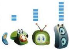
A: Engineers must design the products to be the most appealing at the best price. Product appearance helps marketing sell the product. Product performance is also important and engineers are given specifications by marketing to meet their requirements. Safety is always very important. An
audio device should only be loud enough to serve the specifications. Production Engineers use electronic and magnetic sensors to automate production. Civil engineers design roads and bridges that are safe for everyone to use.
natural_image
Illustration of cartoon characters and media icons (no text or symbols)12. Environmental Engineering - Battery Recycling

Q: How do Engineers help protect our environment?

A: Batteries contain a number of toxic chemicals and their improper disposal may cause soil contamination and water pollution. Engineers know that most typical kinds of batteries can be recycled, especially lead-acid automotive batteries which are nearly 90% recycled today. Nickel-
cadmium (Ni-Cd), nickel metal hydride (Ni-MH), lithium-ion (Li-ion) and nickel zinc (Ni-Zn) can also be recycled. Engineers are always looking for ways to make products safe like integrating fuses into their designs to prevent overheating and fires.

About Electricity (Mathematics)
13. Ohm's Law
Ohms Law states that Voltage equals Current multiplied by Resistance. If V = Voltage, I = Current, and R = Resistance, then mathematically Ohms Law is V = I x R where "x" stands for "multiplied by". Since the law starts with Voltage, we need a voltage source or a Power Supply. There are both DC (direct current) and AC (alternating current) power supplies. Batteries are also a source of DC voltage. Using Algebra, any one unknown can be calculated if the other two variables are known. For example, if V=9 Volts and R=1000 Ohms, then I=0.009 Amp or 9 milliamps.
15. Using Mathematics to Calculate Fuses
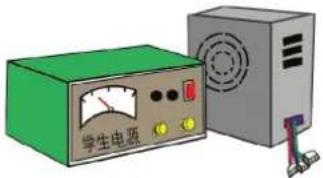
Many different appliances can be connected to draw current from the outlets in your homes. If these outlets are all connected to one fuse, then the fuse must be able to handle the sum of all the currents being drawn. Fuses are used in the battery holder that comes with this product. Each current drawn from any outlet in your home will add up as the appliances are turned ON because they are all connected in parallel.



14. Switches and Power
A switch is a device that may control other components in the circuit. It is used for power connection and disconnection. A switch is a device that is either ON or OFF and used often in digital electronics. Power is the product of the current in a device multiplied by the voltage across it. Electronic Power is expressed in Watts. Mathematically this is expressed as W = V x I. If you have a 60 Watt light that is on a voltage of 120 Volts, then the current can be calculated to be 60 Watts divided by 120 Volts, which equals 1/2 Amp. Some switches are controlled by magnets and others by temperature.


16. Calculating Resistance
Conductive paths are used to connect circuits and transfer electricity. If the voltage on one end of the conductor is lower than on the other end when current is flowing, then the conductor has resistance. The voltage drop on the conductor divided by the current in the conductor is the Resistance of the conductor
or wire. In Mathematical terms and from Ohms law, this would be stated as R = V ÷ l . If the voltage drop is 2 Volts when 4 Amps is flowing, then the resistance of the conductor is 1/2 Ohm.

natural_image
Illustration of various cable and wire components including a yellow cable, red tape, green rope, and black cord (no text or symbols)About Electricity (STEM)
17. Circuit Blox™
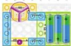
For Circuit Blox™, the definition of an electrical circuit is: The complete path for an electric current flow, usually including the source of electric energy. The path shown in the circuit below is from the battery, through the blue 2-wire, through the motor under the fan, through the blue 4-wire, through the switch, through the blue 2-wire, and then back to the battery. If the switch in this circuit is closed, then current will flow from the
battery through all the components and back to the battery. If enough current flows, the motor will spin and launch the fan. If the switch is open, nothing will happen since it is an open circuit with no current.
19. Sound and Light
There are many modules in Circuit Blox ^™ that will produce different sounds and different light effects.
The Three-in-One module, for example, has two control inputs (T1, T2), a speaker connection (SP1, SP2), and music & space sound selects (I/O1, I/O2).
By proper connection of parts with the Three-in-one module many special effects can be generated and triggered in different ways. This module will be used to simulate many of the different interesting problems in the fields of Sound Technicians, Medical Engineering, Communication Engineers, Home Security, and much more.

flowchart
graph TD
    A["Top Left"] --> B["Top Right"]
    B --> C["Top Left"]
    C --> D["Top Right"]
    D --> E["Top Left"]
    E --> F["Top Right"]
    F --> G["Top Left"]
    G --> H["Top Right"]
    H --> I["Top Left"]
    I --> J["Top Right"]
    J --> K["Top Left"]
    K --> L["Top Right"]
    L --> M["Top Left"]
    M --> N["Top Right"]
    N --> O["Top Left"]
    O --> P["Top Right"]
    P --> Q["Top Left"]
    Q --> R["Top Right"]
    R --> S["Top Left"]
    S --> T["Top Right"]
    T --> U["Top Left"]
    U --> V["Top Right"]
    V --> W["Top Left"]
    W --> X["Top Right"]
    X --> Y["Top Left"]
18. Short Circuits in Circuit Blox™
The battery holder that comes with your Circuit Blox™ Kit is fully protected. A short circuit indicator LED lights and a beeper sounds if any of the outputs are shorted or under a high current draw. It is important that you always use this battery holder in the circuits you build to protect the batteries and prevent damage to parts. Even shorts from one voltage output to another is protected by a
patented circuit and will indicate an excessive current. This circuit uses resettable Positive Temperature Fuses (PTCs). Circuit Blox™ kits are always approved by independent safety laboratories to insure all users will be able to experiment without worry of harm to parts or themselves.

20. Semiconductors
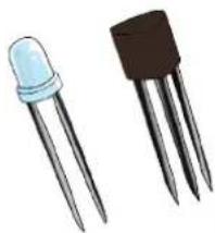
Semiconductors have properties that can control current flowing through a conductor similar to a faucet controlling the flow of water in a pipe. A diode acts like a check valve in a water pipe by only letting current flow in one direction. A Light Emitting Diode (LED) produces light when very little current flows. Different
colored LEDs are made and some LEDs can even produce Laser light similar to handheld pointers or gun scopes. Transistors have three leads and one is used to control the current between the other two.
natural_image
Illustration of two types of LED diodes: a light blue tip and a black three-pin transistor (no text or symbols)Parts List (colors and styles may vary) Symbols and Numbers
Important: If any parts are missing or damaged, DO NOT RETURN TO RETAILER. Call toll-free (855) MY EBLOX (693-2569) or e-mail us at: support@myeblox.com. Customer Service: 880 Asbury Dr., Buffalo Grove, IL 60089 U.S.A.
| Qty. Name Symbol Part # | |||
| 3 | 1-wireBlock |  | 6EB2X01 |
| 8 | 2-wireBlock |  | 6EB2X02 |
| 3 | 3-wireBlock | 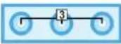 | 6EB2X03 |
| 3 | 4-wireBlock | 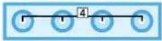 | 6EB2X04 |
| 1 | 5-wireBlock | 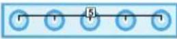 | 6EB2X05 |
| 1 | 6-wireBlock |  | 6EB2X06 |
| 2 | PressSwitch |  | 6EB2X61 |
| 1 Switch | [HXY] | 6EB2X62 | |
| 1 Lamp | 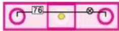 | 6EB2X76 | |
| Qty. Name Symbol Part # | |||
| 1 LED |  | 6EB2X70 | |
| 1 | Reed Switch |  | 6EB2X83 |
| 1 | Spring Wire |  | 6EB2X09 |
| 1 | Base Grid |  | 6EB2X39 |
| 3 | Motor Shaft Cap |  | 6EB2X60A |
| 3 | Motor Top |  | 6EB2X64 |
| 1 | Touch Plate | 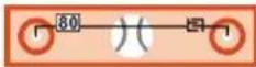 | 6EB2X80 |
| 1 Speaker |  | 6EB2X93 | |
| 1 Magnet |  | 6EB2X07 | |
| 3 | Fan Blade |  | 6EB2X60 |
| 1 Motor |  | 6EB2X95 | |
| 1 Volume | 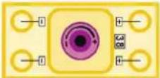 | 6EB2X38 | |
| 2 | Level Block |  | 6EB2X100 |
| 2 | Level Block |  | 6EB2X200 |
| Qty. Name Symbol Part # | |||
| 1 | Three-in-One |  | 6EB2X11 |
| 1 | Power Amplifier | 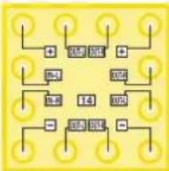 | 6EB2X14 |
| 1 | FM Radio | 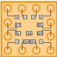 | 6EB2X24 |
| 1 | Battery Holder | 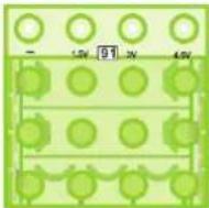 | 6EB2X91 |
| 1 | Battery Cover | 6EB2X91C | |
How to Use Your E-Blox® Circuit Blox™ Set
E-Blox® Circuit Blox™ parts contain a PC board with connectors so you can build the different electrical and electronic circuits in the projects. Each block has a function: there are switch blocks, a light block, battery block, wire blocks, etc. These blocks are different colors and have numbers on them so that you can easily identify them.
For Example:
This is the press switch, it is green and has the marking 61 on it. The part symbols in this booklet may not exactly match the appearance of the actual parts, but will clearly identify them.

This is a wire block which comes in 5 different lengths. The part has the number 1, 2, 3, 4, or 5 on it depending on the length of the wire connection required.
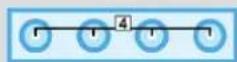
There are also 1-post and 2-post blocks that are used as a spacer or for interconnection between different layers.


You need a power source to build each circuit. The part is marked 91 and requires three (3) 1.5V "AA" batteries (not included). The four connections are marked -, 1.5V, 3V, and 4.5V.
A short circuit indicator LED lights and beeper sounds if any of the outputs are shorted or under a high current draw.

Only use the battery holder when the cover is securely in place.
A large clear plastic base grid is included with this kit to help keep the circuit blocks properly spaced. You will see evenly spaced posts that the different blocks plug into.
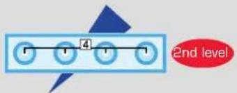
Next to the assemble drawing may be a part with an arrow and red circle as shown below. This indicates that the part is installed below other parts and which level it is on.
About Your E-Blox® Circuit Blox™ Parts
(Part designs are subject to change without notice).
The base grid functions like the printed circuit boards found in most electronic products. It is a platform for mounting parts and wire blocks (though the wires are usually “printed” on the board).
The blue wire blocks are just wires used to connect other components, they are used to transport electricity and do not affect circuit performance. They come in different lengths to allow orderly arrangement of connections on the base grid.
The spring wire (9) is two single blocks connected by a wire used to make unusual connections.
The batteries (91) produce an electrical voltage using a chemical reaction. This “voltage” can be thought of as electrical pressure, pushing electrical “current” through a circuit. This voltage is much lower and much safer than that used in your house wiring. Using more batteries increases the “pressure” and so more electricity flows.
The switch (62) connects (ON) or disconnects (OFF) the wires in a circuit.
The press switch (61) connects (pressed) or disconnects (not pressed) the wires in a circuit, just like the switch does.
A reed switch (83) is an electrical switch operated by an applied magnetic field. When exposed to a magnetic field, the switch closes (ON). When the magnetic field is removed the switch opens (OFF).
The blue level blocks (100 & 200) are non-conductive and just used as building blocks.
The touch plate (80) is a type of switch when both electrodes are touched together using your finger, shorts the two electrodes and a small amount of current flows, activating the circuit.
The LED (70) is a light emitting diode inside the star, and may be thought of as a special one-way light bulb. In the "forward" direction (indicated by the "arrow" in the symbol) electricity flows if the voltage exceeds a turn-on threshold (between 1.8V to 3.3V typically); brightness then increases. A high current will burn out the LED, so the current must be limited by other components in the circuit. LEDs block electricity in the "reverse" direction.
The 4.5V lamp (76) contains a special wire (filament) that glows bright when a large electric current passes through it. Voltages above the bulb's rating can burn out the wire.
The motor (95) converts electricity into mechanical motion. Electricity is closely related to magnetism, and an electric current flowing in a wire has a magnetic field similar to that of a very, very tiny magnet. Inside the motor are three coils of wire with many loops. If a large electric current flows through the loops, the magnetic effects become concentrated enough to move the coils. The motor has a magnet inside, so as the electricity moves the coils to align them with the permanent magnet, the shaft spins.
About Your E-Blox® Circuit Blox™ Parts
The speaker (93) converts electricity into sound. It does this by using the energy of a changing electrical signal to create mechanical vibrations (using a coil and magnet similar to that in the motor). These vibrations create variations in air pressure which travel across the room. You "hear" sound when your ears feel these air pressure variations.
The volume (38) block contains two 50kΩ resistors, adjustable from 200Ω to 50kΩ. In series with the center tap is a 200Ω resistor to limit the current.
Some types of electronic components can be superminiaturized, allowing many thousands of parts to fit into an area smaller that your fingernail. These "integrated circuits" (ICs) are used in everything from simple electronic toys to the most advanced computers.
The FM radio (24) contains an integrated FM radio circuit. Refer to the figure below for the pin-out description:

See project #116 for an example of proper connections.
FM Radio:
[+] - power from batteries
[-] - power return to batteries
RF - antenna input
VOL - volume adjust connection
CH+ - tune up
CH-- tune down
OUT-L - left channel output connection
OUT-R - right channel output
The power amplifier IC (14) block is a module containing an integrated circuit amplifier and supporting components that are always needed with it. A description of it is given here for those interested:

flowchart
graph TD
    A["+"] --> B["二极管"]
    B --> C["正极管"]
    C --> D["+"]
    E["负极管"] --> F["正极管"]
    F --> G["负极管"]
    G --> H["+"]
    I["正极管"] --> J["负极管"]
    J --> K["正极管"]
    K --> L["-"]
Power Amplifier IC:
(+) - power from batteries
(-) - power return to batteries
OUT-L - left channel output connection
OUT-R - right channel output
IN-L - left channel input
IN-R - right channel input
The three-in-one (11) modules contain specialized sound-generation ICs and other supporting components (resistors, capacitors, and transistors) that are always needed with them. This was done to simplify the connections you need to make to use them. The pin descriptions are given here for those interested, see the projects for connection examples:

flowchart
graph TD
    A["↑"] --> B["+"]
    B --> C["+"]
    C --> D["+"]
    D --> E["↓"]
    E --> F["→"]
    F --> G["11"]
    G --> H["→"]
    H --> I["↓"]
    I --> J["→"]
    J --> K["10"]
    K --> L["→"]
    L --> M["↓"]
    M --> N["→"]
    N --> O["10"]
    O --> P["→"]
    P --> Q["10"]
    Q --> R["→"]
    R --> S["10"]
    S --> T["→"]
    T --> U["10"]
    U --> V["→"]
    V --> W["10"]
    W --> X["→"]
    X --> Y["10"]
    Y --> Z["→"]
Three-in-One:
T1, T2 - control inputs
SP1-speaker-connection
SP2-speaker+connection
I/01 - music select
1/02 - space sound select
(+) - power to batteries
(-) - power return to batteries
DOs and DON'Ts of Building Circuits
After building the circuits given in this booklet, you may wish to experiment on your own. Use the projects in this booklet as a guide, as many important design concepts are introduced throughout them. Every circuit will include a power source (the batteries), a resistance (which might be an LED, lamp, motor, integrated circuit, etc.), and wiring paths between them and back. You must be careful not to create “short circuits” (very low-resistance paths across the batteries, see examples below) as this will damage components and/or quickly drain your batteries. Only connect the parts using configurations given in the projects, incorrectly doing so may damage them. E-Blox ^® is not responsible for parts damaged due to incorrect wiring.
Here are some important guidelines:
DO USE EYE PROTECTION WHEN EXPERIMENTING ON YOUR OWN.
DO include at least one component that will limit the current through a circuit, such as the speaker, lamp, LED, integrated circuit (IC, which must be connected properly), or motor.
DO disconnect your batteries immediately and check your wiring if something appears to be getting hot.
DO check your wiring before turning on a circuit.
DO connect the IC using configurations given in the projects or as per the connection descriptions for the part.
DON'T connect to an electrical outlet in your home in any way.
DON'T leave a circuit unattended when it is turned on.
DON'T touch the motor when it is spinning at high speed.
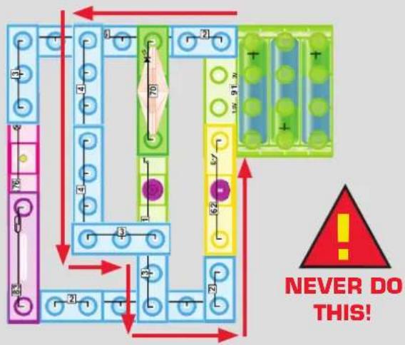
Examples of SHORT CIRCUITS - NEVER DO THIS!
Placing a wire block directly across the battery holder is a SHORT CIRCUIT, indicated by a flashing LED in the battery holder.


When the switch (S1) is turned on, this large circuit has a SHORT CIRCUIT path (as shown by the arrows). The short circuit prevents any other portions of the circuit from ever working.
flowchart
graph TD
    A["Start"] --> B["Step 1"]
    B --> C["Step 2"]
    C --> D["Step 3"]
    D --> E["Step 4"]
    E --> F["Step 5"]
    F --> G["End"]
    style A fill:#f9f,stroke:#333
    style G fill:#bbf,stroke:#333
    note right of G: "NEVER DO THIS!"
    classDef red arrow fill:#fff,stroke:#000;
    classDef green arrow fill:#fff,stroke:#000;
    class A,B,C,D,E,F,G,H,I,J,K,L,M,N,O,P,Q,R,S,T,U,V,W,X,Y,Z,Z,N,O,P,Q,R,S,T,U,V,X,Y,Z,Z,N,N,N,N,N,N,N,N,N,N,N,N,N,N,N,N,N,N,N,N,N,N,N,N,N,N,N,N,N,N,N,N,N,N,N,N,N,N,N,N,N,N,N,N,N,N,N,N,N,N,N,N,N,N,N,N,N,N,N,N,N,N,N,N,N,N,N,N,N,N,N,N,N,N,N,N,N,N,N,N,N,N,N,N,N,N,N,N,N,N,N,N,N,N,N,N,N,N,N,N,n,Q,R,S,T,U,V,X,Y,Z,Z,Z,K,L,M,N,O,P,Q,R,S,T,U,V,X,Y,Z,Z,K,L,M,N,O,P,Q,R,S,T,U,V,X,Y,Z,Z,K,L,M,N,O,P,Q,R,S,T,U,V,X,Y,Z,Z,K,L,M,N,O,P,Q,R,S,T,U,V,X,Y,Z,Z,K,L,M,N,O,P,Q,R,S,T,U,V,X,Y,Z,Z,K,L,M,N,O,P,Q,R,S,T,U,V,X,Y,Z,Z,K,L,M,N,O,P,Q,R,S,T,U,V,X,Y,Z,Z,K,l,m,n,O,p,q,r,s,t,u,v,w,v,x,y,z,k,l,m,m,n,O,p,q,r,s,t,u,v,w,v,x,y,z,k,l,m,m,n,O,p,q,r,s,t,u,v,x,y,z,k,l,m,m,n,O,p,q,r,s,t,u,v,x,y,z,k,l,m,m,n,O,p,q,r,s,t,u,v,x,y,z,k,l,m,m,n,O,p,q,r,s,t,u,v,x,y,z,k,l,m,m,n,O,p,q,r,s,t,u,v,x,y,z,k,l,m,m,n,O,p,q,r,s,t,u,v,x,y,z,k,l,m,m,n,O,p,q,r,s,t,u,v,x,y+z,k,l,m,m,n,O,p,q,r,s,t,u,v,x,y,z,k,l,m,m,n,O,p,q,r,s,t,u,v,x,y,z,k,l,m,m,n,O,p,q,r,s,t,u,v,x,y,z,k,l,m,m,n,O,p,q,r,s,t,u,v,x,y,z,k,l,m,m,n,O,p,q,r,s,t,u,v,x,y,z,k,l,m,m,n,O,p,q,r,s,t,u,v,x,y,z,k,l,mm,n,O,p,q,r,s,t,u,v,x,y,z,k,l,m,m,n,O,p,q,r,s,t,u,v,x,y,z,k,l,m,m,n,O,p,q,r,s,t,u,v,x,y,z,k,l,m,m,n,O,p,q,r,s,t,u,v,x,y,z,k,l,m,m,n,O,p,q,r,s,t,u,v,x,y,z,k,l,m,m,n,O,p,q,r,s,t,u,v,x,y,z,k,l,m,m,n,O,p q,r,s,t,u,v,x,y,z,k,l,m,m,n,O,p,q,r,s,t,u,v,x,y,z,k,l,m,m,n,O,p,q,r,s,t,u,v,x,y,z,k,l,m,m,n,O,p,q,r,s,t,u,v,x,y,z,k,l,m,m,n,O,p,q,r,s,t,u,v,x,y,z,k,l,m,m,n,O,p,q,r,s,t,u,v,x,y,z,k,l,m,m,n,O,p,q,r,s,t,a,b,c,d,e,f,g,h,i,j,k,l,m,m,n,O,p,q,r,s,t,u,v,x,y,z,k,l,m,m,n,O,p,q,r,s,t,u,v,x,y,z,k,l,m,m,n,O,p,q,r,s,t,u,v,x,y,z,k,l,m,m,n,O,p,q,r,s,t,u,v,x,y,z,k,l,m,m,n,O,p,q,r,s,t,u,v,x,y,z,k,l,m,m,n,O,p,q,r,s,t,u,v,x,y,z,k,l,m m,n,O,p,q,r,s,t,u,v,x,y,z,k,l,m,m,n,O,p,q,r,s,t,u,v,x,y,z,k,l,m,m,n,O,p,q,r,s,t,u,v,x,y,z,k,l,m,m,n,O,p,q,r,s,t,u,v,x,y,z,k,l,m,m,n,O,p,q,r,s,t,u,v,x,y,z,k,l,m,m,n,O,p,q,r,s,t,u,v,x,y,z,k,l,m,m,n,O,p.q,r,s,t,u,v,x,y,z,k,l,m,m,n,O,p,q,r,s,t,u,v,x,y,z,k,l,m,m,n,O,p,q,r,s,t,u,v,x,y,z,k,l,m,m,n,O,p,q,r,s,t,u,v,x,y,z,k,l,m,m,n,O,p,q,r,s,t,u,v,x,y,z,k,l,m,m,n,O,p,q,r,s,t,u,v,x,y,z,k,l,m,m,n,O,p,q,r,s,t,t,u,v,x,y,z,k,l,m,m,n,O,p,q,r,s,t,u,v,x,y,z,k,l,m,m,n,O,p,q,r,s,t,u,v,x,y,z,k,l,m,m,n,O,p,q,r,s,t,u,v,x,y,z,k,l,m,m,n,O,p,q,r,s,t,u,v,x,y,z,k,l,m,m,n,O,p,q,r,s,t,u,v,x,y,z,k,l,m,m,n,O,p,q,r,s,t,u,v x,y,z,k,l,m,m,m,n,O,p,q,r,s,t,u,v,x,y,z,k,l,m,m,n,O,p,q,r,s,t,u,v,x,y,z,k,l,m,m,n,O,p,q,r,s,t,u,v,x,y,z,k,l,m,m,n,O,p,q,r,s,t,u,v,x,y,z,k,l,m,m,n,O,p,q,r,s,t,u,v,x,y,z,k,l,m,m,n,O,p,q,r,s,t,u,v,x,y,z,k,l,m,m,n O,p,q,r,s,t,u,v,x,y,z,k,l,m,m,n,O,p,q,r,s,t,u,v,x,y,z,k,l,m,m,n,O,p,q,r,s,t,u,v,x,y,z,k,l,m,m,n,O,p,q,r,s,t,u,v,x,y,z,k,l,m,m,n,O,p,q,r,s,t,u,v,x,y,z,k,l,m,m,n,O,p,q,r,s,t,u,v,x,y,z,k,l,m,m,n,O,p,q,r,\( ^{1} \) ]

WARNING: SHOCK HAZARD! Never connect E-Blox® Circuit Blox™ to the electrical outlets in your home in any way!
Advanced Troubleshooting (adult supervision recommended)
E-Blox® is not responsible for parts damaged due to incorrect wiring.
If you suspect you have damaged parts, you can follow this procedure to systematically determine which ones need replacing:
- Lamp (76), LED (70), Battery Holder (91): Place part directly across the battery holder as shown, it should
light. If none work, then replace your batteries and repeat, if still bad then the battery holder is damaged. Make sure the LED is installed in the correct direction.

- Wire Blocks (1-5), Spring Wire (9), and Speaker (95): Use this mini-circuit to test each of the Wire Blocks and Speaker (95), one at a time. The lamp (76) should light if the part is functioning properly. Follow the steps below:
Spring Wire test - Build the circuit shown below. The lamp (76) should light.
Wire Block tests - Insert the Wire Blocks between the spring wire to lamp connection shown in the figure. The lamp should light.

Speaker test - Insert the speaker (95) between the spring wire to lamp connection shown in the figure. The speaker will not sound, but the lamp will light.
- Motor (95): Place the motor across the battery holder (95 at top) as shown; it should spin clockwise.
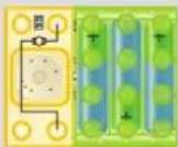
- Switch (62), Press switch (61), Reed Switch (83), Touch Plate (80): Use this circuit to test each switch and the touch plate (80). The lamp (76) should light. If the lamp doesn't light, then the switch is bad.
Switch - Up position the lamp off, Down position lamp on.
Press - Light when switch is pressed.
Reed - When you place the magnet on the switch the lamp should light.
Touch Plate - Wet your finger; when you touch the contacts, the

- Three-In-One (11): Siren & Machine Gun - Build project #49, you should hear a siren sound from the speaker.
Space Battle - Build project #52, you should hear a space battle sound from the speaker.
Music - Build project #47, you should hear a music from the speaker.
E-Blox®
880 Asbury Dr., Buffalo Grove, IL 60089 U.S.A.
Phone/Fax:(855)MY EBLOX(693-2569)
e-mail: help@myeblox.com ● Website: www.myeblox.com
You may order additional / replacement parts at: www.pickabrick.com
Project Listings
| # Description | Page | # Description | Page |
| 1. Closed Circuit 18 | 31. Ship-to-Ship Morse Code | 30 | |
| 2. LED, the Check Valve Light 18 | 32. Reversing a DC Motor | 30 | |
| 3. Magnetic Switch 18 | 33. Electronic 'AND' Gate | 31 | |
| 4. Alarm Switches 18 | 34. Electronic 'OR' Gate | 31 | |
| 5. The 'Momentary' Switch 19 | 35. Triple Input 'AND' Gates | 32 | |
| 6. Electrical to Mechanical Energy 19 | 36. Triple Input 'OR' Gate | 32 | |
| 7. Proximity Sensor 20 | 37. Series-Parallel Circuit Paths 33 | ||
| 8. Newton's First Law of Motion 20 | 38. Series-Parallel Circuit Paths 2 | 34 | |
| 9. Newton's Second Law of Motion 21 | 39. Individually Switch-controlled Electrical Appliances | 35 | |
| 10. Launching versus Latching Forces 21 | 40. Main Switch with Motor Press Switch-controlled Electrical Appliances | 36 | |
| 11. Magnet-controlled Flying Saucer 21 | 41. OR Gate Controlling Parallel Electrical Appliances | 37 | |
| 12. Parts Connected in Series 22 | 42. AND Gate Controlling Parallel Electrical Devices | 38 | |
| 13. Inertia 22 | 43. Three-Person Rocket Launch | 39 | |
| 14. Parts Connected in Parallel 22 | 44. Siren | 40 | |
| 15. Electrical Current Indicators | 23 | 45. Machine Gun Sounds | 41 |
| 16. Power 'ON' Indicator | 23 | 46. Space Battle Sounds | 42 |
| 17. Electronic Efficiency | 24 | 47. Music (I) | 43 |
| 18. House Wiring | 24 | 48. Emergency Fire Siren | 44 |
| 19. Ohm's Law | 25 | 49. Touch-controlled Sound Effects 45 | |
| 20. Kirchhoff's First Law | 25 | 50. Siren Sound Effects | 45 |
| 21. Kirchhoff's Second Law | 26 | 51. Magnet-controlled Alarm Siren 45 | |
| 22. The Resettable Fuse | 26 | 52. Space Battle Sounds | 46 |
| 23. Motor Speed | 27 | 53. Touch-controlled Sound of Space Battle | 46 |
| 24. Simulation of a PTC-fused Lamp | 28 | 54. Magnet-controlled Sounds of Space Battle | 46 |
| 25. Fused Motors | 28 | 55. Music (II) | 47 |
| 26. Ohm's Law Revisited | 28 | 56. Reset Switch | 47 |
| 27. Magnet Does Two Jobs | 28 | 57. Touch Reset | 47 |
| 28. Magnet 2-speed Fan | 29 | 58. Proximity Music Or Warning | 47 |
| 29. Speed-controlled Fan | 29 | 59. Siren & White light Warning | 48 |
| 30. Testing Conductors | 29 | 60. Gun with Flash on Shot | 48 |
Project Listings
| # Description | Page | # Description | Page |
| 61. Fire Siren & White light Warning 48.... | 91. Parallel LED Resistance 56.... | ||
| 62. Magnet-controlled Fire Siren with White light Warning 48 | 48 | 92. Mr. Magnet's Birthday.... | 56 |
| 63. Five Space Battle Sound Effects 49.... | 93. Birthday Party Disc Jockey.... | 56 | |
| 64. Cycling Through Space Battle Sounds 49.... | 94. Flickering Candle.... | 57 | |
| 65. Proximity Warning of an Alien Craft 49.... | 95. Silent Morse Code.... | 57 | |
| 66. Music with a Light Beat 50.... | 96. Automated Code.... | 57 | |
| 67. Repeat Button 50.... | 97. Magnet Lights the Candle.... | 57 | |
| 68. One Finger Disc Jockey 50.... | 98. Two-channel Monitor.... | 58 | |
| 69. Proximity Music Interrupt 50.... | 99. Silent Search for Signals.... | 58 | |
| 70. Distant Siren with Indicator 51.... | 100. Geiger Counter.... | 58 | |
| 71. Battle Far, Far Away 51.... | 101. Four Beats per Second 59.... | ||
| 72. Many Sirens in the Distance 51.... | 102. Taking a Rest.... | 59 | |
| 73. No Touch Special Effects 51.... | 103. Touch-controlled Slow Flashing Lamp.... | 59 | |
| 74. In a Galaxy Far, Far Away.... | 52 | 104. Magnet-controlled Slow Flashing Lamp.... | 59 |
| 75. Control Drone in Battle.... | 52 | 105. Erratic Heartbeat.... | 60 |
| 76. Mixing and Repeating Sound Effects.... | 52 | 106. Heart Failure and Shock.... | 60 |
| 77. Automated Sound Effect.... | 52 | 107. Simulating CPR.... | 60 |
| 78. Soft Playing Heartbeat Music.... | 53 | 108. The Pacemaker.... | 61 |
| 79. Quiet Musical Chairs Game 53.... | 109. Different Heartbeats.... | 61 | |
| 80. Stop the Music Game.... | 53 | 110. Attention Please.... | 61 |
| 81. One Finger Restart.... | 53 | 111. Proximity-controlled Sign.... | 61 |
| 82. Nearby Siren.... | 54 | 112. Normal Heartbeat.... | 62 |
| 83. Bank Robbery Starts.... | 54 | 113. Morse Code Heartbeat 62.... | |
| 84. More Sound Engineering Tricks.... | 54 | 114. Flashing Quick Sale Sign.... | 62 |
| 85. Magnet Helps Sound Effect Engineer.... | 54 | 115. Flashing Alarm Light.... | 62 |
| 86. Engineering a Space Battle.... | 55 | 116. FM Radio.... | 63 |
| 87. Sound Technicians.... | 55 | 117. FM Radio in a Medium Volume.... | 64 |
| 88. Perfect Timing Counts.... | 55 | 118. FM Radio with Level Meter.... | 65 |
| 89. Changing Power ON Effect.... | 55 | 119. Adjustable Radio Volume.... | 66 |
| 90. Music Loudness Reduction.... | 56 | 120. Adjustable Radio Volume with Level Meter.... | 67 |

1. Closed Circuit
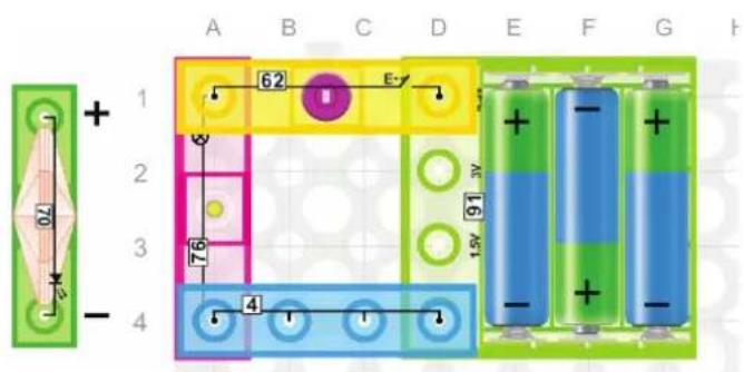
E-Blox® Circuit Blox™ uses electronic blocks that plug into a clear plastic grid to build different circuits. These blocks have different colors and numbers on them so that you can easily identify them.
Build the circuit shown on the left by placing all the parts that plug into the first layer base. Then, assemble the parts that connect to the secondary layer. Install three (3) "AA" batteries (not included) into the battery holder (91). Secure the battery cover before using it.
Pressing the switch (62) creates a closed circuit; the lamp (76) will turn on. Press it again to open the circuit and the lamp (76) will turn off.
2. LED, the Check Valve Light
Replace the lamp (76) with the LED (70), making sure it's in the correct direction. Press the switch (62) to turn it ON and OFF. Reverse the LED (70) and repeat. Notice that the LED does not light when in the circuit in the reverse direction, demonstrating how LEDs only allow current to flow in one direction.
3. Magnetic Switch
Build the circuit on the left. Put the magnet (7) near the reed switch (83) and the lamp (76) will turn on. Move the magnet (7) away and the lamp (76) will turn off. This is a "no touch" switch!
4. Alarm Switches
Replace the lamp (76) with the LED (70), making sure it's in the correct direction. Put the magnet (7) near the reed switch (83) and the LED (70) will turn on. Move the magnet (7) away and the LED (70) will turn off. House alarms sometimes use reed switches to detect when a door or window is open.

5. The 'Momentary' Switch
Build the circuit to the left. Press and hold the press switch [61] and the lamp [76] will turn on. Release the press switch [61] and the lamp [76] will turn off. Replace the lamp [76] with the LED [70] making sure the LED is in the correct direction, and repeat above directions. This type of switch is called a 'momentary' switch since it is only on when pressed.
6. Electrical to Mechanical Energy
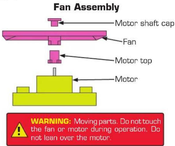
Assemble the fan by following the assembly diagram below. Build the circuit to the left. Press the switch (62) and the fan will spin as long as the switch is pressed. Electrical energy from the batteries (91) has been changed to mechanical energy by the motor (95).

7. Proximity Sensor
Build the circuit on the left, then move the magnet (7) near the reed switch (83) and the motor (95) will turn on. Move the magnet (7) away and the motor (95) will turn off. Proximity sensing like this is often used to control things like blow drying your car in a car wash.

WARNING: Moving parts. Do not touch the fan or motor during operation. Do not lean over the motor.
8. Newton's First Law of Motion
Build the circuit on the left, press and hold the press switch (61) and the fan (60) will start spinning. Release the press switch (61), the fan will slow down and finally stop due to friction in the motor (95). This demonstrates Newton's First Law of Motion: An object either remains at rest or continues to move at a constant velocity, unless acted upon by a force.

WARNING: Moving parts. Do not touch the fan or motor during operation. Do not lean over the motor.
9. Newton's Second Law of Motion
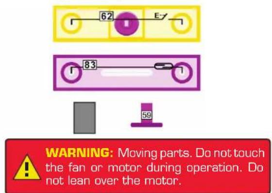
Remove the cap (59) that is on the fan blade (60). Hold the press switch (61) for ten seconds. Release the press switch (61) and the flying saucer should take off (Caution! Never let it fly near your face!). If the fan does not fly, make sure the batteries are fresh, the motor (95) is in the correct direction, and give the fan a tap from underneath with the top of your fingernail. This circuit demonstrates Newton's Second Law of Motion: acceleration is produced when a force acts on a mass. In this case, air pressure under the fan blade forces it to rise.

Reminder: Remove the shaft cap (59) before launching the flying saucer.
10. Launching versus Latching Forces
Replace the press switch (61) with the switch (62) and turn the motor (95) on. Wait for the motor (95) to reach top speed. If the fan does not launch, then the force in the motor latch is greater than the air pressure. Press the switch (62) again and the fan should launch. If the fan does not fly, make sure the batteries are fresh, the motor is in the correct direction, and give the fan a tap from underneath with the top of your fingernail.
11. Magnet-controlled Flying Saucer
Replace the press switch (61) with the reed switch (83) and move the magnet (7) towards the reed switch (83). Wait for a few seconds, then move the magnet (7) away to launch the saucer. A reed switch is typically made from two or more ferrous reeds (thin strips) encased within a small glass tube-like envelope, which become magnetized and move together or separate when a magnetic field is moved towards the switch.

12. Parts Connected in Series
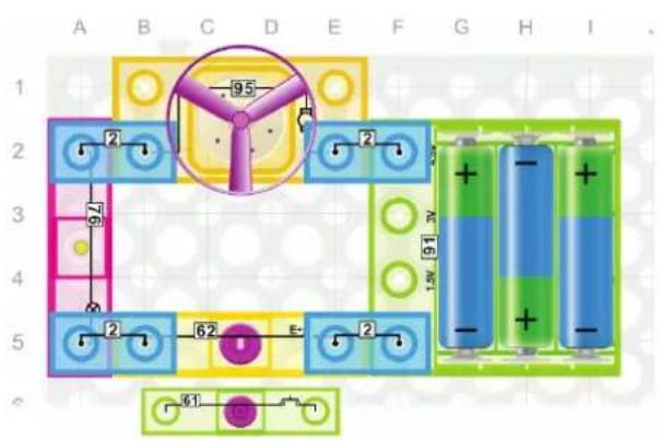
Build the circuit to the left. When the switch (62) is ON, the same current will flow through the motor (95) then through the lamp (76) and both will be active. When the switch (62) is OFF, the circuit is open and current will be zero, so everything will stop. Notice that the fan spins slower in this circuit than in project #6. This is because the lamp (76) has resistance so when put in series with the motor (95), it limits the current flowing in the circuit.
13. Inertia
Replace the switch (62) with the momentary switch (61). Press the press switch (61) to make the fan spin and the lamp (76) light. Release the press switch (61) and the fan will keep spinning, but the lamp (76) will turn off immediately. This circuit demonstrates the concept of Inertia: a property of matter by which it continues in its existing state of rest or uniform motion in a straight line, unless that state is changed by an external force. The fan has inertia but the lamp does not.
14. Parts Connected in Parallel
Build the circuit on the left and turn ON with the switch (62). The fan will start spinning & the lamp (76) will be on as well. Notice that the fan spins faster in this circuit than in project #12. This is because the lamp (76) and motor (95) in this circuit are in parallel, allowing each to have separate paths for current flow. Thus the resistance in the lamp (76) does not limit the current flow through the motor (95).


15. Electrical Current Indicators
Build the circuit to the left and turn ON with switch (62). Both the lamp (76) and the LED (70) will light up. This demonstrates that electrical current is flowing through both parts. Turn OFF the power and turn both the lamp (76) and LED (70) around. Turn ON the switch (62) and the LED (70) will be OFF but the lamp (76) will be ON. This demonstrates that current is only flowing through the lamp. The lamp (76) and the LED (70) are very simple devices that can be used to detect current flow. A more advanced device, called an ammeter, is used to measure the amount of electrical current flowing in a circuit.
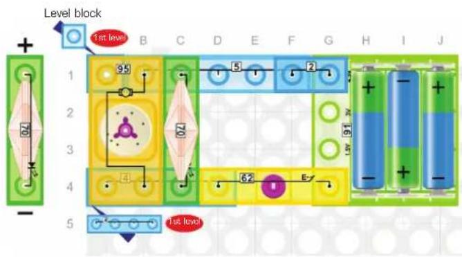
16. Power 'ON' Indicator
Build the circuit to the left. Press the switch (62), the LED (70) will light up and the motor (95) will start spinning. Without the fan blade it is difficult to see if the motor is 'ON' when far from the circuit. With the LED in parallel with the motor, a visual indicator that the motor is 'ON' can be seen from a distance. LEDs are often used on electrical devices to show they are 'ON'. Wasted "Watts" cost money and is bad for the environment.

17. Electronic Efficiency
Electronic Efficiency is defined as the Useful Power Output divided by the Total Power Input.
Build the circuit to the left and press the switch [62]. The LED (70) will light, but the lamp (76) will not light. There is resistance built into the LED (70) to protect it (too much current could damage an LED), and this resistance is limiting the current in the circuit. Yet this circuit shows that the LED (70) is more efficient than the lamp (76) because it still produces light (useful output power) even at the lower current.

18. House Wiring
Build the circuit to the left. Turn ON the switch (62) and the LED (70), the lamp (76), and the motor (95) will all be on at the same time. In this circuit the LED (70), the lamp (76), and the motor (95) are in parallel. Pretend the LED is a television, the motor is a ceiling fan, and the lamp is a house lamp on an end table. Just like in your home, you can turn any one of these OFF by removing them from the circuit and the rest will stay ON. This demonstrates why your house wiring uses parallel circuits and not series circuits.
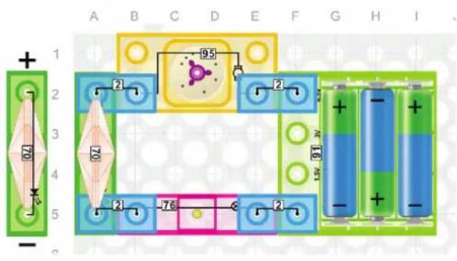
19. Ohm's Law
Using Ohm's Law the resistance of each part could be calculated.
Build the circuit to the left. In this circuit the motor (95), the LED (70), and the lamp (76) are in series so they all see the same current. If you had a voltmeter and measured the voltage drop across each component, you would see that the voltage drop across the LED (70) is much greater than the voltage drop across the lamp (76) or motor (95).
According to Ohm's Law, R = V ÷ l which means the internal resistance of the LED (70) is much greater than the internal resistance of the lamp (76) or motor (95). The high internal resistance of the LED (70) is limiting the current in this circuit, which is why the motor (95) spins very slowly and the lamp (76) does not light. Each part is designed using Ohm's Law to perform best when they have full battery voltage.

flowchart
graph TD
    A["Level 1"] --> B["Level 2"]
    B --> C["Level 3"]
    C --> D["Level 4"]
    D --> E["Level 5"]
    style A fill:#f9f,stroke:#333
    style B fill:#ccf,stroke:#333
    style C fill:#cfc,stroke:#333
    style D fill:#fcc,stroke:#333
    style E fill:#cff,stroke:#333
    subgraph Level 1
        F["07"] --> G["62"]
        H["76"] --> I["4"]
        J["95"] --> K["7"]
        L["2"]
        M["4"]
        N["4"]
        O["2"]
        P["2"]
        Q["2"]
        R["2"]
    end
    subgraph Level 2
        S["07"] --> T["62"]
        U["76"] --> V["4"]
        W["95"] --> X["7"]
        Y["2"]
        Z["4"]
        AA["4"]
        AB["2"]
        AC["2"]
        AD["2"]
    end
    subgraph Level 3
        AE["07"] --> AF["62"]
        AG["76"] --> AH["4"]
        AI["95"] --> AJ["7"]
        AK["2"]
        AL["4"]
        AM["2"]
        AN["2"]
        AO["2"]
    end
    subgraph Level 4
        AP["07"] --> AQ["62"]
        AR["76"] --> AS["4"]
        AT["95"] --> AU["7"]
        AV["2"]
        AW["4"]
        AX["2"]
        AY["2"]
    end
    subgraph Level 5
        AZ["07"] --> BA["62"]
        BB["76"] --> BC["4"]
        BD["95"] --> BE["7"]
        BF["2"]
        BG["4"]
        BH["2"]
        BI["2"]
        BJ["2"]
    end
20. Kirchhoff's First Law
Kirchhoff's first law states: At any node (junction) in an electrical circuit, the sum of currents flowing into that node is equal to the sum of currents flowing out of that node.
Build the circuit on the left. The top block shown in red as "2nd level" represents a node. If a positive current is coming into a node and a negative current is leaving a node, then:
$$ I _ {\text { switch }} + I _ {\text { motor }} + I _ {\text { lamp } \& \text { LED }} = 0 \quad \text { or } \quad I _ {\text { switch }} = - I _ {\text { motor }} - I _ {\text { lamp } \& \text { LED }} $$
This shows that the current flowing into node E1 from the switch is equal to the current flowing out of node E1 to the motor and lamp&LED.
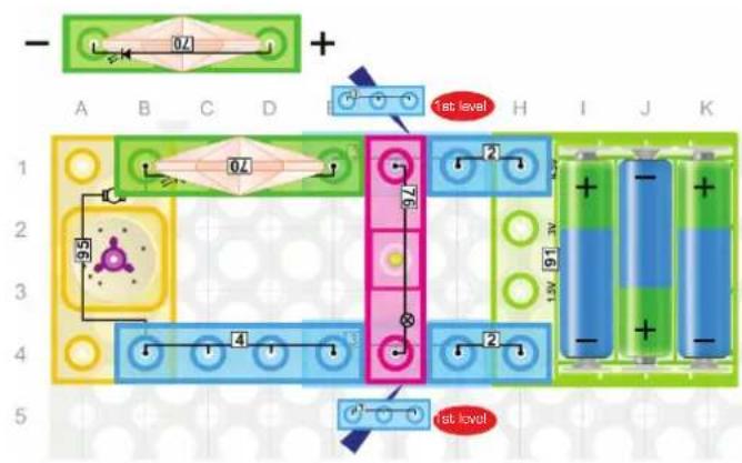

21. Kirchhoff's Second Law
Kirchhoff's second law states: The sum of the voltages around a closed network is zero.
Build the circuit to the left. If a drop in voltage is considered as a negative voltage and a rise in voltage a positive voltage, then the following equation is a mathematical representation of Kirchhoff's second law:
$$ \mathrm{V} _ {\mathrm{H4} \rightarrow \mathrm{H1}} + \mathrm{V} _ {\mathrm{H1} \rightarrow \mathrm{A1}} + \mathrm{V} _ {\mathrm{A1} \rightarrow \mathrm{A4}} + \mathrm{V} _ {\mathrm{A4} \rightarrow \mathrm{H4}} = 0 $$
This shows that the voltage drop across the battery module (91) of 4.5V must equal the voltage drop across the LED (70) plus the voltage drop across the motor (95). From project #19 we saw that the voltage drop across the LED (70) was high, and thus the voltage drop across the motor (95) was small, which is why the motor spun slowly. But a similar Kirchhoff equation shows that the voltage drop across the lamp (76) is the full 4.5V, which is why the lamp (76) is bright.
22. The Resettable Fuse
Positive-Temperature-Coefficient, or PTC, thermistors – also known as resettable fuses are devices that have very low resistance until a current is reached, then they get warm and the resistance changes limit the current.
Build the circuit to the left. Notice that the lamp (76) is not lit and the motor (95) does not spin. In this circuit the white glowing LED (70) is acting like a warm activated PTC fuse by limiting the current to the motor (95) and lamp (76). Replace the LED (70) with a 4-wire (4) and the lamp (76) and motor (95) will now get the current they need to operate properly.

23. Motor Speed
Build the circuit to the left and press and hold the press switch (61). The LED (70) will light indicating the motor has voltage, the lamp (76) will light dimly showing that current is coming from the motor (95) and the motor (95) will spin slowly. The motor (95) spins slower in this circuit than in project #8. Remove the LED (70) from the circuit and place the fan blade on the motor (95) to make the reduction in speed even more obvious. Because the lamp (76) has resistance, current flowing through the lamp (76) produces a voltage drop and the motor (95) gets less voltage due to Kirchhoff's second law. Less voltage on the motor (95) explains why the fan spins more slowly.
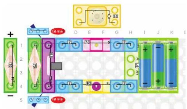

24. Simulation of a PTC-fused Lamp
Build the circuit to the left and turn ON the switch [62]. The LED (70) will glow white simulating the PTC fuse is warm. Pretend the magnet (7) is a piece of ice and place it near the reed switch (83). The PTC fuse cools down, allowing current to flow and the lamp (76) to light.
25. Fused Motors
Replace the lamp (76) with the motor (95). Some motors have fuses that pop-out when they are triggered. Move the magnet (7) away from the reed switch (83) to simulate a fuse that has popped, making the motor (95) spin more slowly. Simulate resetting the fuse by moving the magnet back next to the reed switch (83). Motors are designed with fuses to limit the current that can be seen by the motor to prevent fires.
26. Ohm's Law Revisited
Build the circuit to the left. Press the switch [62], the lamp [76] will turn on very dimly and the motor [95] will turn on at the same time. Remove the motor resistance by pressing the press switch [61] and the lamp [76] will become brighter. Per Ohm's Law, given the same voltage [4.5V], a lower resistance in the circuit leads to a larger current in the circuit which is why the lamp [76] gets bright when you press the press switch [61].
27. Magnet Does Two Jobs
Replace the press switch (61) with the reed switch (83), by using the magnet (7) you can control the brightness of the lamp (76) and turn the motor (95) OFF at the same time. You may have noticed that the magnet (7) can be attracted to the motor (95). This is because motors have magnets inside to create a magnetic field that spins the motor when current flows through the motor.

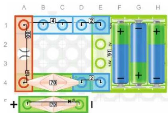

28. Magnet 2-speed Fan
Build the circuit to the left. Press the switch (62), the lamp (76) will turn on dimly and the fan will spin slowly. Did you notice that the lamp (76) started out being bright and then got dim? This is because motors have very high startup currents, but once they gain speed the current through the motor drops. You can increase the speed of the motor (95) and fan in this circuit by moving the magnet towards the reed switch (83).
29. Speed-controlled Fan
Replace the reed switch [83] with the press switch [61]. By pressing the press switch [61] you can control the speed of the fan. This demonstrates how the fan speed in the ceiling fan in your house is changed when you pull the chain on the ceiling fan.
30. Testing Conductors
Build the circuit to the left. This tester can check whether a material is conductive or not. You just need to connect the material across the touch plate's (80) shiny area. If the LED (70) turns on it means the material is a conductor. If the LED (70) does not turn on, it means the material is an insulator. The brightness of the LED (70) also tells how good a conductor the material is, where better conductors make the LED (70) brighter and poorer conductors make the LED (70) dimmer. You may be able to see the brightness level of the LED (70) better in a dark room.


31. Ship-to-Ship Morse Code
Press the press switch (61), the LED (70) will blink. This can be used as a Morse code typing simulator. Morse code uses various sequences of long and short on-off tones, lights or clicks to represent letters, numbers, and text. Since World War II, the process for sending messages using signal lamps has barely changed. It requires someone trained in Morse code to operate the lamp's shutter by hand, receiving, decoding, and replying to messages.
32. Reversing a DC Motor
Build the circuit to the left. Press and hold the press switch (61) and the fan blade (60) will spin clockwise. Release the press switch (61), the motor (95) will stop. Now put the motor (95) in backwards using 3-wires (3) instead of 2-wires (2). Press and hold the press switch (61) and the fan blade (60) now spins counterclockwise. Notice that the direction the motor (95) spins is related to the direction the current flows through the motor (95). This is because the force created on the motor shaft is related to the direction that the current flows through the magnetic field in the motor (95). You can look up Fleming's left hand rule for more details on how the relationship between the current flow, magnetic field and force that creates motion.

WARNING: Moving parts. Do not touch the fan or motor during operation. Do not lean over the motor.

33. Electronic 'AND' Gate
Build the circuit to the left. Note that the lamp [76] only turns on when both the switch [62] and press switch [61] are ON. In digital electronics there are seven logic gates: AND, OR, XOR, NOT, NAND, NOR, and XNOR. This circuit represents an AND gate. If ON = True and OFF = False then an AND gate is best defined as: The output is TRUE only when both inputs are True. Therefore, the two inputs represented by the press switch [61] and the switch [62] must both be ON (TRUE) in order for the output represented by the lamp [76] to be ON (TRUE).
34. Electronic 'OR' Gate
Build the circuit to the left. This circuit represents an OR gate. If ON = True and OFF = False, then an OR gate is best defined as: The output is TRUE when any input is True and False only when all the inputs are False. In this circuit the output represented by the lamp (76) is ON (True) if either input represented by the press switch (61) or the switch (62) or both is ON (TRUE). The lamp (76) is OFF (False) only when both switches are OFF (False).
![A B C D E F G H I J K L 4 2 76 2 61 2 62 E- 1.5V [9] mV + - + - + -](/content/2026/05/1060702/images/67bf63551462464f4d56787760fed9c72583028ec18853314937440b644975a1.jpg)
35. Triple Input 'AND' Gate
Build the circuit on the left, turn the switch (62) ON, press and hold the press switch (61) to turn it ON, and move the magnet (7) towards the reed switch (83). Only when all three switches (INPUTS) are ON (True) will the lamp (OUTPUT) be ON (True). Electronic AND Gates can have two or more inputs but the function is still the same. All inputs must be True (ON) for the output to be True (ON).

36. Triple Input 'OR' Gate
Build the circuit on the left, making sure all switches are OFF. The lamp [76] should be OFF. Turn ON any one of the switches and the lamp will be ON. To turn off the lamp, all of the switches must be OFF. Electronic OR Gates can have two or more inputs but the function is still the same. All inputs must be False (OFF) for output to be False (OFF).

37. Series-Parallel Circuit Paths
Build the circuit above. In this circuit, the lamp (76) that indicates current flow cannot turn on by just turning the switch (62) ON. If you turn the switch (62) ON and press and hold the press switch (61), then current will flow. Or if you turn the switch (62) ON and move the magnet (7) towards the reed switch (83), then current will flow. Since switch (62) is in series with the other two switches that are in parallel, this makes a series-parallel circuit path for the lamp (76). This kind of circuit could be used in a hotel room where your key card must be inserted in a card holder near the door to enable a closed circuit, but you still need to turn on switches in the room to have certain lights or devices close the circuit and turn on.

38. Series-Parallel Circuit Paths 2
Build the circuit above. There are two ways to light the lamp (76) in this circuit. You can either press the switch (62), or place the magnet (7) next to the reed switch (83) and press the press switch (61). Using the hotel analogy from the last project, the reed switch (83) could represent the key card holder and the press switch (61) could be a light in the room. But this room now has a master key card holder that only the employees (e.g. maids) at the hotel have keys for that turns on all the lights in the room regardless of which switches are turned on or off in the room.
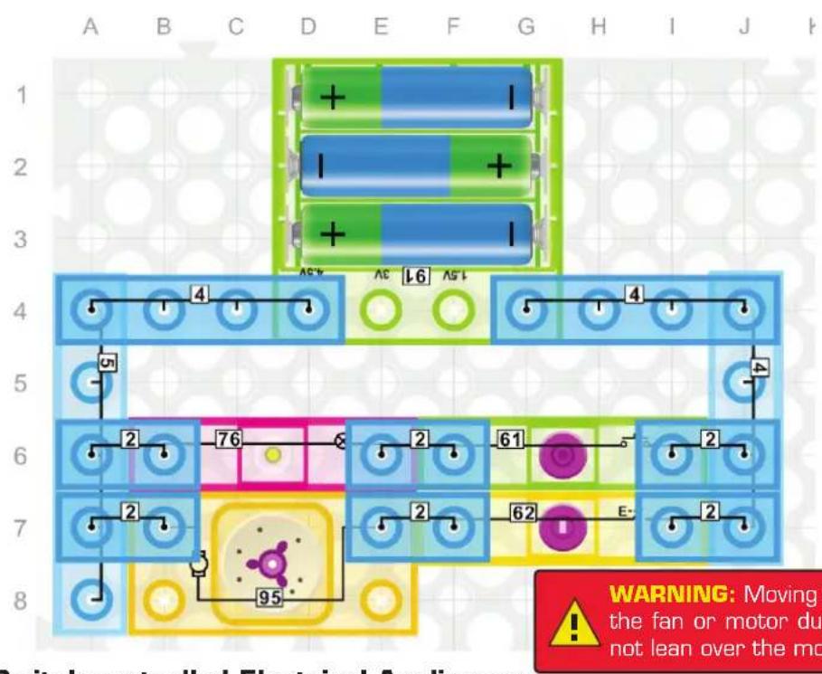
39. Individually Switch-controlled Electrical Appliances
Build the circuit above. Press the switch (62) and the motor (95) will start spinning. Press the switch (62) again and the motor (95) will stop. Press and hold the press switch (61) and the lamp (76) will turn on. Release the press switch (61) and the lamp (76) will turn off.
In rooms with ceiling fans there are typically two switches on the wall with a circuit like this where one switch turns on and off the fan and one switch turns on and off the light in the room.


WARNING: Moving parts. Do not touch the fan or motor during operation. Do not lean over the motor.
40. Main Switch with Motor Press Switch-controlled Electrical Appliances
Build the circuit above. Press the switch (62), the lamp (76) will light up. Press and hold the press switch (61), the motor (95) will turn on. Now press the switch (62) again, both the lamp (76) and the motor (95) will turn off. Switch (62) is the Main Switch. You could think of the switch (62) in this circuit like the circuit breaker in your house (if you turn off the circuit breaker in your house then no devices or switches will work in your house).
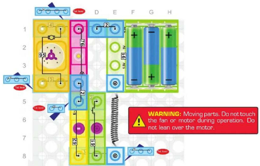
41. OR Gate Controlling Parallel Electrical Appliances
Build the circuit above. Press either the press switch (61) OR the switch (62) to turn on the lamp (76) and the motor (95). If you want to turn off the lamp (76) or turn off the motor (95), both the press switch (61) and the switch (62) must be OFF. You might think this type of circuit could be used to have multiple switches in a room control the same device(s). However, this type of circuit is not ideal because the switches do not toggle with each other. In your house, if you pushed the switch (62) ON to turn on your lights, then if you pressed the press switch (61) you would want your lights to go OFF. Your house uses three-way switches to do this, not the circuit above.

flowchart
graph TD
    A["1st level"] --> B["2"]
    B --> C["3"]
    C --> D["4"]
    D --> E["5"]
    E --> F["6"]
    F --> G["7"]
    G --> H["8"]
    H --> I["9"]
    I --> J["10"]
    J --> K["11"]
    K --> L["12"]
    L --> M["13"]
    M --> N["14"]
    N --> O["15"]
    O --> P["16"]
    P --> Q["17"]
    Q --> R["18"]
    R --> S["19"]
    S --> T["20"]
    T --> U["21"]
    U --> V["22"]
    V --> W["23"]
    W --> X["24"]
    X --> Y["25"]
    Y --> Z["26"]
    Z --> AA["27"]
    AA --> AB["28"]
    AB --> AC["29"]
    AC --> AD["30"]
    AD --> AE["31"]
    AE --> AF["32"]
    AF --> AG["33"]
    AG --> AH["34"]
    AH --> AI["35"]
    AI --> AJ["36"]
    AJ --> AK["37"]
    AK --> AL["38"]
    AL --> AM["39"]
    AM --> AN["40"]
    AN --> AO["41"]
    AO --> AP["42"]
    AP --> AQ["43"]
    AQ --> AR["44"]
    AR --> AS["45"]
    AS --> AT["46"]
    AT --> AU["47"]
    AU --> AV["48"]
    AV --> AW["49"]
    AW --> AX["50"]
42. AND Gate Controlling Parallel Electrical Devices
Build the circuit above. In the paralleled connection, to start the motor (95) and light the lamp (76), turn the switch (62) ON, AND turn ON switch (61) at the same time. The motor (95) and the lamp (76) will turn on. Sometimes, for safety reasons, it is required that two switches be ON before machinery will run.
flowchart
graph TD
    A["1st level"] --> B["Blue Battery"]
    B --> C["Green Battery"]
    C --> D["Blue Battery"]
    D --> E["Blue Battery"]
    E --> F["Blue Battery"]
    F --> G["Blue Battery"]
    G --> H["Blue Battery"]
    H --> I["Blue Battery"]
    I --> J["Blue Battery"]
    J --> K["Blue Battery"]
    K --> L["Blue Battery"]
    L --> M["Blue Battery"]
    M --> N["Blue Battery"]
    N --> O["Blue Battery"]
    O --> P["Blue Battery"]
    P --> Q["Blue Battery"]
    Q --> R["Blue Battery"]
    R --> S["Blue Battery"]
    S --> T["Blue Battery"]
    T --> U["Blue Battery"]
    U --> V["Blue Battery"]
    V --> W["Blue Battery"]
    W --> X["Blue Battery"]
    X --> Y["Blue Battery"]
    Y --> Z["Blue Battery"]
    Z --> AA["Blue Battery"]
    AA --> AB["Blue Battery"]
    AB --> AC["Blue Battery"]
    AC --> AD["Blue Battery"]
    AD --> AE["Blue Battery"]
    AE --> AF["Blue Battery"]
    AF --> AG["Blue Battery"]
    AG --> AH["Blue Battery"]
    AH --> AI["Blue Battery"]
    AI --> AJ["Blue Battery"]
    AJ --> AK["Blue Battery"]
43. Three-Person Rocket Launch
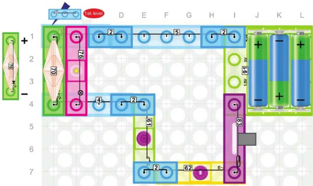
Build the circuit above. In this circuit, pretend the lamp (76) and the LED (70) are a rocket. To launch the rocket the switch (62) must be ON, AND the press switch (61) must be ON, AND the reed switch (83) must be turned ON with the magnet (7). Systems like this are used to prevent accidental rocket launching by having the switches placed far enough apart that it requires three people to turn them on simultaneously.
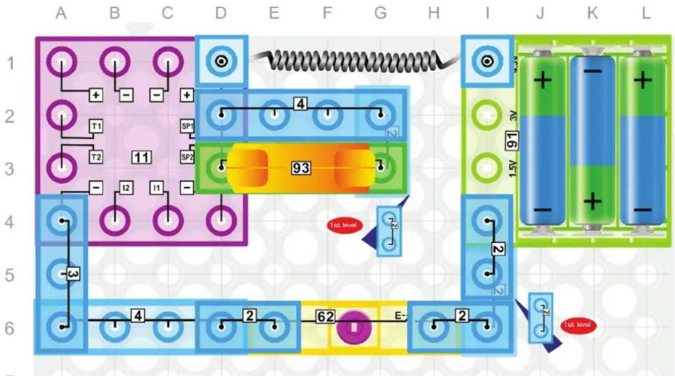
44. Siren
Build the circuit above. Press the switch (62) and you will hear the siren from the speaker (93). The Three-in-One (11) contains an Integrated Circuit (IC) that produces the siren sound. An IC is a set of electronic circuits on one small flat piece (or "chip") of semiconductor material, normally silicon. ICs enable much more complicated circuits to be designed in orders of magnitude smaller, cheaper, and faster manners than those constructed using discrete electronic components.

45. Machine Gun Sounds
Build the circuit above. Press the switch (62), you will hear some siren sounds from the speaker (93). When you touch and release the touch plate (80) you will hear a gun sound. Continually press the touch plate (80) and now you will hear machine gun sounds. Sound technicians use electronics like this on the job.

46. Space Battle Sounds
Press the switch [62], you will hear space battle sounds from the speaker [93]. Press the press switch [61] multiple times and the space battle sounds will change. Note that the 4-wire [4] on the Three-in-One [11] in this circuit is activating the space war sounds by grounding the I/O2 pin. In electronics this type of input is called "active low".

47. Music (I)
Build the circuit above. Press the switch [62] and the speaker [93] will play music. This music is electronically generated and stored in this module during production and usually checked by a quality control technician to insure good audio quality.
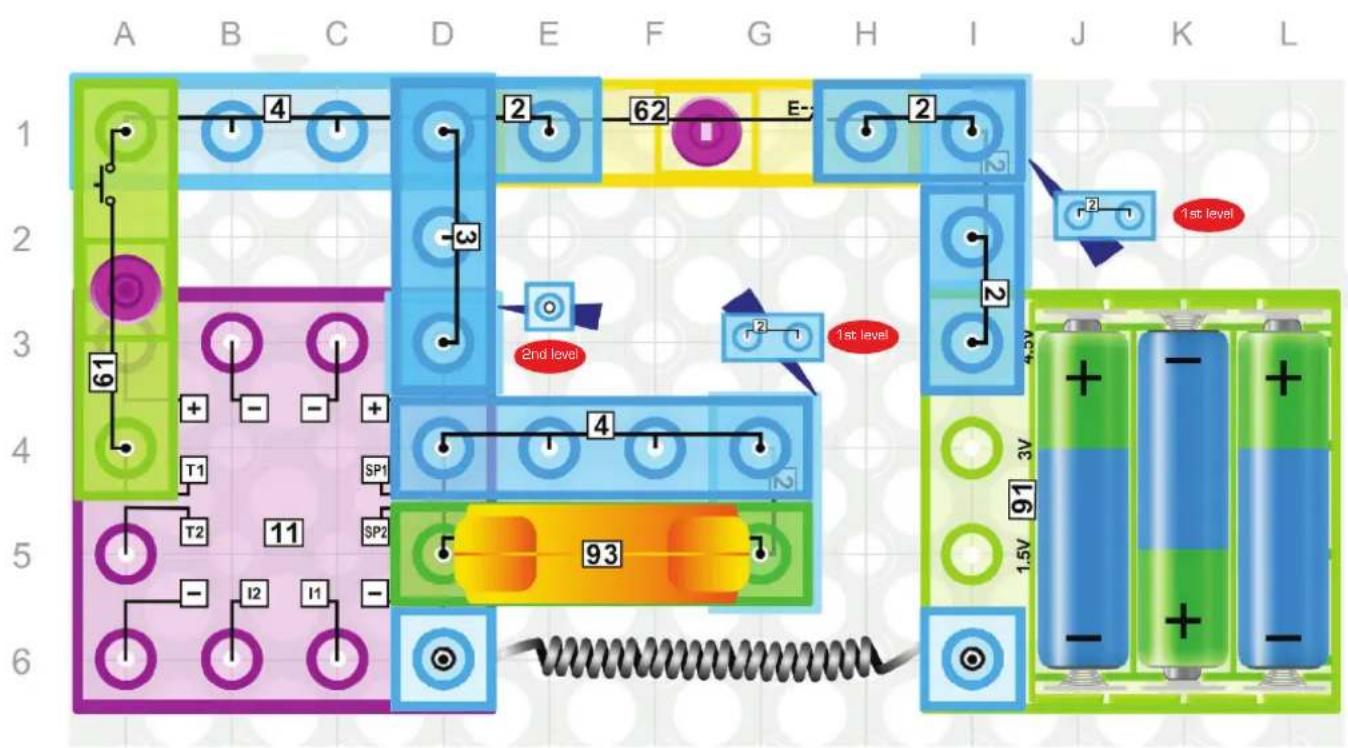
flowchart
graph TD
    A["Component A"] -->|4| B["Component B"]
    B --> C["Component C"]
    C --> D["Component D"]
    D --> E["Component E"]
    E --> F["Component F"]
    F --> G["Component G"]
    G --> H["Component H"]
    H --> I["Component I"]
    I --> J["Component J"]
    J --> K["Component K"]
    K --> L["Component L"]

    subgraph Level Indicator
        direction LR
        A -->|61| B
        B -->|-3| C
        C -->|+| D
        D -->|-2| E
        E -->|2| F
        F -->|2| G
        G -->|2| H
        H -->|2| I
        I -->|2| J
        J -->|1st level| K
        K -->|93| L

    subgraph Power Supply
        direction LR
        A -->|T1| B -->|SP1| C -->|SP2| D -->|SP1| E -->|SP2| F -->|SP2| G -->|SP2|
        B -->|-11| C -->|-12| D -->|-11| E -->|-12|
        C -->|-11| F -->|-12|
        D -->|-12| G -->|-12|
        E -->|-12| H -->|-12|
        F -->|-12| I -->|-12|
        G -->|-12| J -->|-12|
        H -->|-12| K -->|-12|
        I -->|-12| L -->|-12|
    end

    style Level Indicator fill:#f9f,stroke:#333,stroke-width:2px
    style Power Supply fill:#ccf,stroke:#333,stroke-width:2px
48. Emergency Fire Siren
Build the circuit above. Press the switch (62) and a siren sound should come from the speaker (93). When you hold the press switch (61) you will hear a fire engine siren. A siren like this is designed by an engineer to cover a large spectrum of sound so all people can hear it, even if they have hearing problems.
49. Touch-controlled Sound Effects
Build the circuit shown. Press the switch (62) and you will hear the siren from the speaker (93). Now touch the touch plate (80) several times and you will hear gun sounds. Hold the touch plate (80) and you will hear machine gun sounds.
Note that in this circuit your finger is a good enough conductor to activate the gun sounds with the touch plate (80) even though your finger was not a good enough conductor to activate the LED (70) in project #30. This is because the input T2 is a low impedance input, which means that it has a very low opposition to current flow. So for input T2, even your finger is a good enough conductor to allow enough current to flow from T2.

50. Siren Sound Effects
Turn the switch (62) ON and you will hear the siren from the speaker (93). Press switch (61) and now you will hear the Fire Engine Siren. Turn OFF the switch (62) and replace the press switch (61) with the touch plate (80).
Turn ON the switch [62] and you will hear the siren, but now when you touch the touch plate [80] it does not activate the Fire Engine Siren. This is because T1 has a higher input impedance so your finger is not a good enough conductor to allow current to flow to T1.
51. Magnet-controlled Alarm Siren
Replace the press switch (61) in the circuit above with the reed switch (83). Move the magnet (7) towards the reed switch (83) and you will hear the Fire Engine Siren. This circuit simulates motion detection alarms that are in your house.
52. Space Battle Sounds
Build the circuit shown here. Turn the switch (62) ON to hear the sounds of space battle from the speaker (93). Sounds will change to different space effects each time you press the press switch (61). Many movie sound effects are made electronically like this.

53. Touch-controlled Sound of Space Battle
Press the switch (62), you will hear the sounds of space battle from the speaker (93). Tap the touch plate (80) several times to change sounds. A touch control helps an Audio Technician quickly change sounds.
54. Magnet-controlled Sounds of Space Battle
Replace the press switch (61) with the reed switch (83). Press the switch (62) and you will hear the sounds of space battle from the speaker (93). Move the magnet near the reed switch (83) several times and the sounds will change. The IC in the Three-in-One (11) is programmed so that both T1 and T2 inputs can change the space war sound.
55. Music (II)
Build the circuit shown. Turn ON the switch (62) and a song should play from the speaker (93). The IC in the Three-in-One (11) is programmed to play music when the I/O1 input is grounded (connected to OV).
56. Reset Switch
Press the switch (62), you will hear some music from the speaker (93). Hold the press switch (61) and the music will restart. Note that the music stops when you release the press switch (61).

57. Touch Reset
Turn the switch (62) ON. Use your finger to touch the touch plate (80) and the music will restart. Finger touching can be faster than a switch to reset music. The circuits in projects #56 and #57 are often used in infant toys where some sounds are made by just touching a button while other sounds require the infant to hold the button.
58. Proximity Music Or Warning
Replace the press switch [61] with the reed switch [83], then press the switch [62]. Moving the magnet [7] towards the reed switch [83] will restart the music. Moving the magnet [7] away will stop the music. The magnet [7] on the reed switch [83] could be like sensors on your car that activate a warning sound when it gets too close to an object.
59. Siren & White light Warning
Build the circuit shown. Press the switch (62) and the siren will be heard from the speaker (93). At the same time you can see the white light flashing in the LED (70). The voltage changes at the speaker input SP2 are changing the voltage across the LED (70), causing it to flicker.
60. Gun with Flash on Shot
Press the switch (62), then use a finger and tap the touch plate (80). The sound of a single gun shot should come from the speaker (93), and the white light LED (70) should flash like the flash of a gun. Hold your finger on the touch plate (80), and a machine gun sound should come from the speaker (93) with the white LED flashing at each shot. This type of a circuit can be used to synchronize lights and sounds to create special effects.
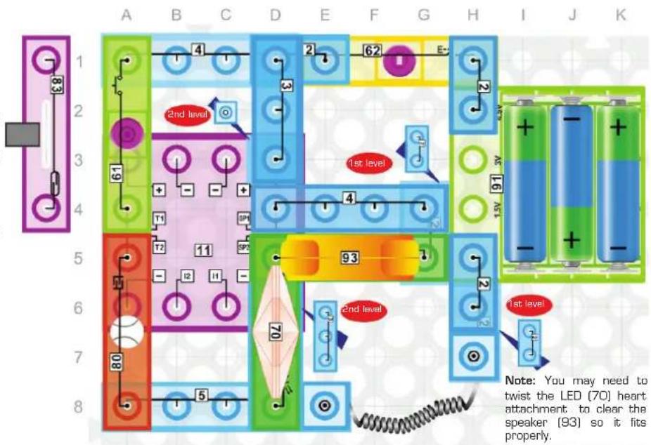
61. Fire Siren & White light Warning
Press the switch (62) and hold down the press switch (61). The sounds of a fire siren will be heard from the speaker (93), with the white light warning on the LED (70). The IC in the Three-in-One (11) uses AND and NAND (Not AND) gate logic to make the fire engine siren sound when T1 is active AND I/01 and I/02 are NOT active.
62. Magnet-controlled Fire Siren with White light Warning
Replace the press switch (61) with the reed switch (83) and press the switch (62). Now you can hear the siren from the speaker (93) with the white light warning on the LED (70). Move the magnet (7) towards the reed switch (83) and now the fire siren is on.
63. Five Space Battle Sound Effects
Build the circuit shown, and turn ON the switch (62). The sounds of space battle may turn on with the white light (LED 70) flashing with each sound. Press the switch (61) to step through the five different battle sounds.
The IC in the Three-in-One [11] has these different sounds stored in memory and accesses them sequentially as you press the press switch [61].

64. Cycling Through Space Battle Sounds
Turn ON the switch (62). Press the press switch (61) and the sounds of a space battle come from the speaker (93). Then use one finger and touch the touch plate (80) a number of times. Notice that the press switch (61) cycles to the next sound while the touch plate (80) cycles to the previous sound. All the logic that determines what sound goes to the speaker (93) when certain inputs are set is pre-programmed into the IC in the Three-in-One (11).
65. Proximity Warning of an Alien Craft
Replace the press switch [61] with the reed switch [83] and turn ON the switch [62]. Move the magnet [7] towards the reed switch [83], the sounds will change as a warning emulating the proximity of an alien craft. Note that because the LED [70] is not in series with the speaker [93], it does not affect the volume of the sound.
66. Music with a Light Beat
Build the circuit and turn ON the switch (62). Notice how the LED (70) beats with the music. This demonstrates how some devices can synchronize light patterns to music.
67. Repeat Button
Turn ON the switch [62] and press the press switch [61] to make the music skip back to the beginning. This demonstrates how the repeat or previous song button operates on a music device works.
68. One Finger Disc Jockey
Turn ON the switch (62). Touch the touch plate (80) to restart the music. You may find the touch plate (80) is faster than the push button switch (61). By letting the song play only a few notes the music is repeated over and over as if you were a Disc Jockey at a party.
69. Proximity Music Interrupt
Replace the press switch (61) with the reed switch (83) then turn ON the switch (62). You will hear music from the speaker (93) with the LED (70) beating. Move the magnet (7) towards the reed switch (83) and the music will be interrupted and restart. Move the magnet (7) away, the music will turn off. In this case, the disc jockey could hold a magnet and just wave their hand over the reed switch to restart a song.
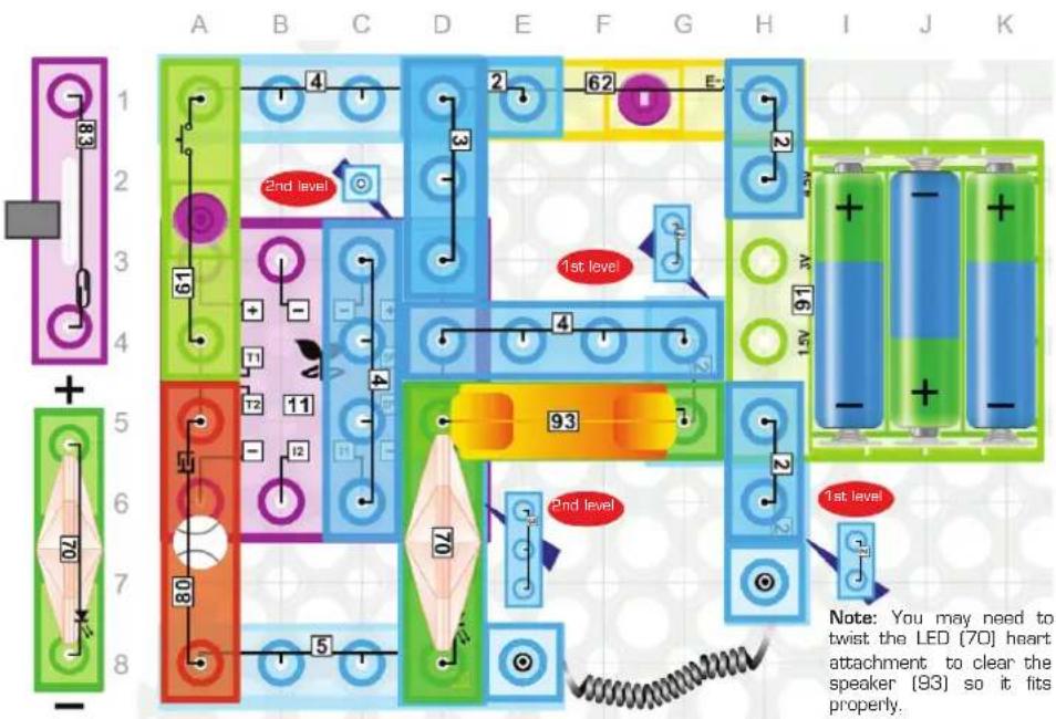
70. Distant Siren with Indicator
Build the circuit and turn ON the switch (62). A distant police siren will come from the speaker (93) with the white light indicator flashing (LED 70). In this circuit the LED (70) is in series with the speaker (93), the voltage drop across the LED (70) reduces the voltage across the speaker (93) reducing the volume of the sound.
71. Battle Far, Far Away
Turn ON the switch (62). A far away siren sound effect will come from the speaker. Touch the touch plate (80) to change the sounds of a far away gun shot. The white light indicator will help indicate sounds from the speaker if the room is noisy and sounds are hard to hear. These are special effects for a space battle in a galaxy far away.
72. Many Sirens in the Distance
Turn on the switch (62). A far away siren should come from the speaker (93). Press the press switch (61) to change to a fire siren in low volume with the flashing white light indicator (LED 70). Try turning the LED (70) around in the circuit. Notice that the LED (70) still flashes and sound is heard from the speaker (93). This is because the speaker (93) does not have polarity, meaning current can flow through it in either direction for it to make sound.
73. No Touch Special Effects
Replace the press switch (61) with the reed switch (83), then press the switch (62). You will hear the far away siren from the speaker (93) while the white light turns on from the LED (70). Move the magnet (7) towards the reed switch (83) to change sound effect without touching the circuit.

- In a Galaxy Far, Far Away Build the circuit, turn ON with the switch (62), and the speaker (93) will produce the sounds of space battle in a far away galaxy. The flashing white light from the LED (70) is indicator that there is sound in case the room is noisy.
75. Control Drone in Battle
Pretend you are controlling a drone in the far away battle by pressing the press switch [61] several times and changing the battle sounds. Sound effect technicians in movie studios (also known as foleys, named after the sound-effects artist Jack Foley), sometimes use this technique.
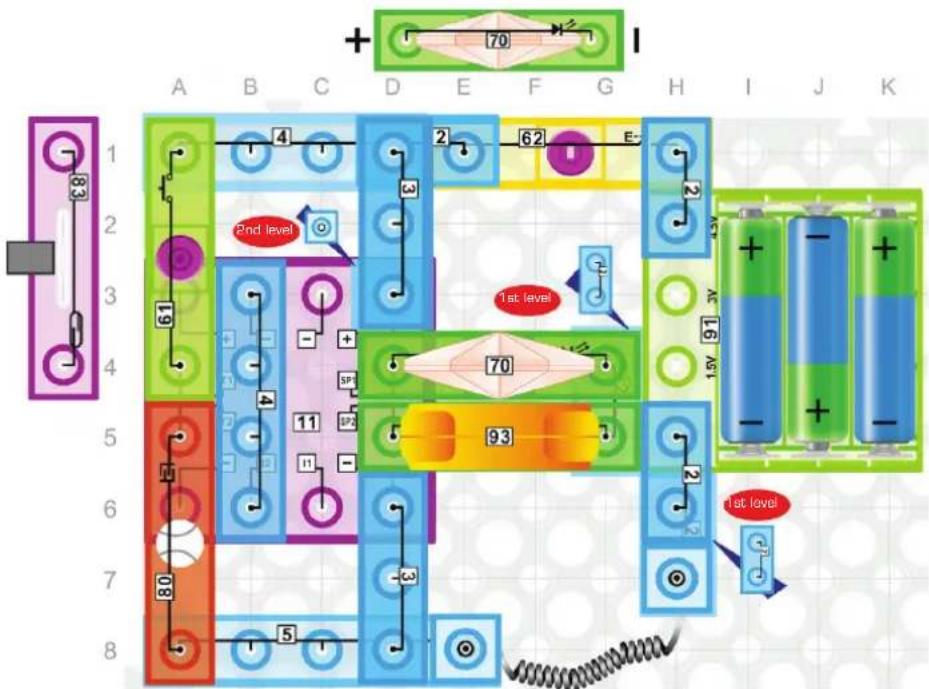
76. Mixing and Repeating Sound Effects
Use the switch (62) to turn ON the circuit. Touch the touch plate (80) to hear gun shots in the distance. The internal resistance in the LED (70) limits the current through the speaker (93) thus reducing the volume of the sound.
77. Automated Sound Effect
Replace the press switch (61) with the reed switch (83), and turn ON the switch (62). After the sound stops, pretend a magnet is in the pocket of a magician on a stage. The magician could perform a trick where he waves his hand to make a speaker make sounds when in reality he is just leaning the magnet closer to the reed switch (83) to turn it on.
-
Soft Playing Heartbeat Music Build the circuit shown, press the switch (62) and you will hear some music in low volume from the speaker (93), with the LED (70) beating to the music. This is a crude example of how an audio spectrum display works on an amplifier/music system.
-
Quiet Musical Chairs Game Tell players they must be very quiet if they want to hear the music. Place chairs in a circle with backs on the inside, one fewer than the number of players. All players stand in circle around the chairs. Press and hold switch (62). Soft music will play with the white light (LED 70) flashing. Let the music play for several seconds then release switch (62) and the music will stop. Each player must sit in a chair, but one will be left out. Remove that player and one chair and repeat until only one player remains.
80. Stop The Music Game
Replace the press switch (61) with the reed switch (83). Blindfold a player and place the circuit nearby in the room. Turn ON the switch (62) and place the magnet on the reed switch (83) to keep the music playing. Record the time required for the player to find and remove the magnet and stop the music. The one with the lowest time is the winner.
81. One Finger Restart
Press the switch [62], you will hear the music play in a low volume from the speaker [93]. Then touch the touch plate [80]. The music will be restarted even if it is still playing.
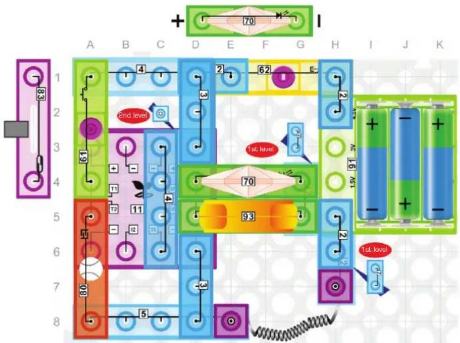
82. Nearby Siren
Build the circuit and turn ON the switch (62). You will hear sounds of a nearby siren and see flashing lights.
83. Bank Robbery Starts
Use this circuit to simulate a bank robbery starting just like a sound technician in a movie production. Use one finger on the touch plate (80). You will hear the sounds of a gun nearby. Then hold the touch plate (80) and you will hear the sounds of a machine gun. The lamp (76) and LED (70) will also turn on to simulate flashes from the gun fight. Try and create your own battle!
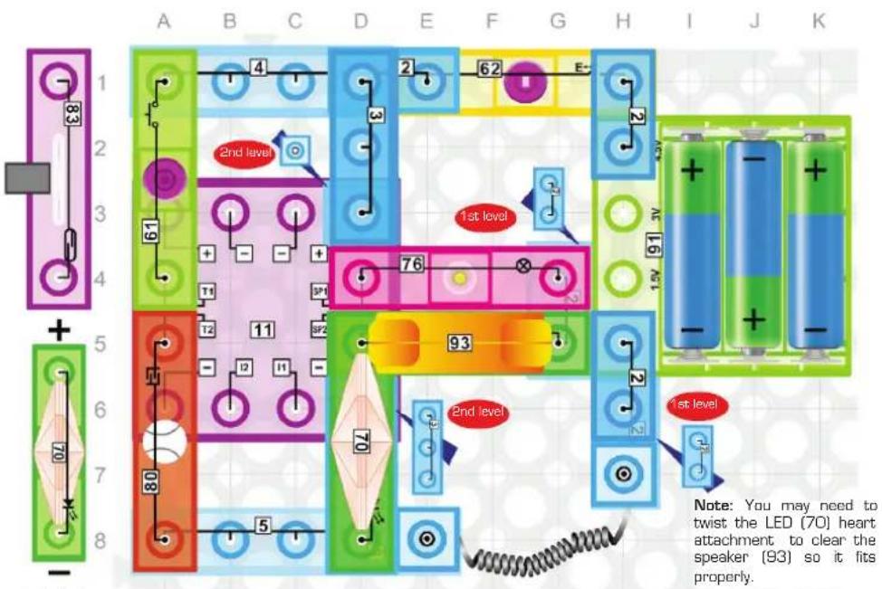
84. More Sound Engineering Tricks
Press the switch [62], you will hear the siren from the speaker [93]. Then press and hold the press switch [61] and you will hear the fire siren or ambulance coming to the scene. A change like this is used by movie set sound engineers to indicate the gun battle may be over.
85. Magnet Helps Sound Effect Engineer
Replace the press switch [61] with the reed switch [83] and turn ON the switch [62]. Change the siren sound by placing the magnet [7] on the reed switch [83]. Pretend you are watching the movie for the final shot. Tap your finger on the touch switch [80] to make a shot that ends the sound effects.
86. Engineering a Space Battle
Build the circuit shown and press the switch (62) to hear the sounds of a nearby space battle. A sound technician on a movie set might start a scene with this effect.
87. Sound Technicians
On movie sets and in many play theaters there are technicians that monitor the sound and create effects. Turn ON the switch (62) and use the press switch (61) to make different space battle sounds that could be used during a movie or play. You are now acting like a sound technician.
88. Perfect Timing Counts
Turn ON the above circuit with the switch (62). Place one finger close to the touch plate (80). Assume three events are going to take place exactly 3 seconds apart. Count to three and touch the touch plate (80) to time sound to event one. Count to three and touch again for event two. Repeat one last time for third event after another three seconds.
89. Changing Power ON Effect
Replace the press switch (61) with the reed switch (83) and place the magnet in position to trigger the reed switch (80). Turn ON the switch (62). The power up sound should now be different than when the magnet is not on the reed switch.
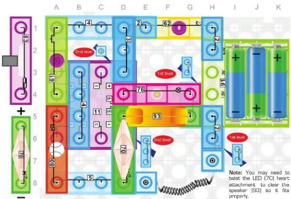
90. Music Loudness Reduction
Build the circuit shown and turn ON the switch (62). Music will play at a reduced volume because the resistance in the lamp (76) is in series with the speaker (93) and reduces the voltage across the speaker.
91. Parallel LED Resistance
Press the switch (62), you will hear some music in medium volume from the speaker (93) with the lamp (76) and LED (70) on. Remove the LED (70) and notice the loudness does not change. This is because the LED (70) is in parallel with the speaker (93) and lamp (76).

92. Mr. Magnet's Birthday
Replace the press switch (61) with the reed switch (83) and turn the power on with switch (62). Put the magnet (7) on the reed switch (83) and do not move it. The birthday song will play as long as the magnet is on the switch. Remove the magnet (Mr. Magnet leaves the party) and the birthday song will stop.
93. Birthday Party Disc Jockey
Turn ON the switch [62]. Use one finger and tap the touch plate [80] to make the music start over and over again. You can make up a birthday rap song while starting over and over.
94. Flickering Candle
Build the circuit and press the switch (62). The lamp (76) will flicker like a candle in a gentle breeze.
95. Silent Morse Code
Turn ON the switch [62], use one finger and tap the touch plate [80] and the lamp [76] will go off. You can now use your finger to tap out a silent Morse code signal in the dark.
96. Automated Code
Press the switch (62), the lamp (76) will flash steadily. Use one finger and tap the touch plate (80) and the lamp (76) will turn off. Hold the touch plate (80) and the lamp (76) will flash quickly as if a very rapid Morse code was being transmitted or received. This is only a simulation and not a real code.
97. Magnet Lights the Candle
Replace the press switch (61) with the reed switch (83) and turn ON the switch (62). Use one finger and tap the touch switch (80) to turn the lamp (76) off. Put the magnet (7) on the reed switch (83) and the lamp (76) will turn on like a lit candle and flash like as if it was in a breeze.
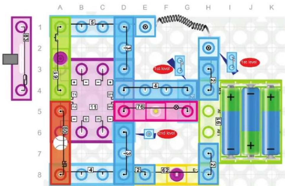
98. Two-channel Monitor
Build the circuit shown and turn ON the switch (62). The lamp (76) will simulate Morse code being silently monitored. Then press the press switch (61) and the simulated Morse code signal will change.
This is similar to what a technician working for the FBI or CIA may see when they change the channel they are monitoring.
Codes are only simulated, not real.
99. Silent Search for Signals
Turn ON the switch (62) and the lamp (76) will flash slowly simulating a transmission being monitored. Use one finger and tap the touch plate (80) several times. The flashing speed of the lamp (76) will change when different transmissions are found. Lamp brightness indicates signal strength.
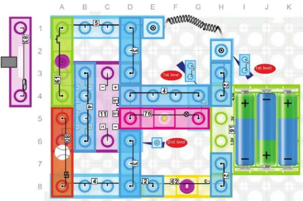
100. Geiger Counter
The Geiger Counter is a device for measuring radioactivity by detecting and counting ionizing particles. Replace the press switch (61) with the reed switch (83) and turn ON the switch (62). The lamp (76) may flash slowly or be off. Move the magnet (7) towards the reed switch (83) and the lamp (76) will turn on or flashing speed of the lamp (76) will increase when a magnetic field is detected. This simulation shows how a Geiger Counter measurement increases when radioactive particles are detected.
101. Four Beats per Second
Build and turn ON the circuit shown. The lamp [76] will flash approximately four times per second.
102. Taking a Rest
Turn ON the switch (62) and if the lamp (76) is flashing press and release the press switch (61) and the lamp (76) will turn off. Now hold the press switch (61) and the lamp (76) will flash the beat again. Release the press switch (61) to take a rest.

103. Touch-controlled Slow Flashing Lamp
Press the switch (62) and the lamp (76) will flash slowly. Press the press switch (61) and the lamp (76) will turn off. Touch the touch plate (80) and the lamp (76) will flash slowly again.
104. Magnet-controlled Slow Flashing Lamp
Replace the press switch (61) with the reed switch (83), press the switch (62) and the lamp (76) will flash slowly. Move the magnet (7) towards the reed switch (83), the lamp (76) will turn off. Now place the magnet (7) on the reed switch (83) and do not move it. The lamp (76) will flash slowly, but when you move the magnet (7) away, the lamp (76) will turn off.
105. Erratic Heartbeat
Build the circuit, press the switch (62) and see an erratic heartbeat.
106. Heart Failure and Shock
Press the switch (62) and the heart LED (70) will flash steadily. Press the press switch (61) and the heartbeat will fail. Touch the touch plate (80) to simulate a shock that makes the heart beat come back on.
107. Simulating CPR
Turn ON the switch (62) and press the press switch (61) to simulate a heart failure. Tap the press switch (61) every three seconds and watch the blood being pushed through the heart. This is the idea behind CPR which stands for cardiopulmonary resuscitation.
108. The Pacemaker
Replace the press switch (61) with the reed switch (83), place the magnet (7) on the reed switch (80) and turn ON the switch (62). Tap the reed switch (80) with the magnet (7) if the heart is not beating. Place the magnet (7) back on the reed switch (80) to simulate a pacemaker is activated. Notice how the heartbeat is now steady. You may have to adjust the magnet to achieve desired effect.


109. Different Heartbeats
Build the circuit and turn ON the switch (62). If the heart (70) is not beating, start by touching the touch plate (80). Change the heartbeat by clicking switch (61). There are many different types of cardiac arrhythmias (pronounced ahr-rith-mee-ahs) ranging from the completely benign to the immediately life threatening. Arrhythmia simply means "abnormal heart rhythm."

110. Attention Please
Press the switch (62) to turn ON power. Tap the touch plate (80), the flashing speed and brightness of the LED (70) will be changed with each tap. Changing LED speed and brightness is often used to attract someone's attention.
111. Proximity-controlled Sign
Replace the press switch [61] with the reed switch [83]. Turn power ON with the switch [62]. Move the magnet [7] towards the reed switch [83] several times to simulate a person walking by a proximity activated sign. The speed and message on the sign could change depending on the time of day.
112. Normal Heartbeat
Build the circuit and turn ON the switch (62). Tap the touch plate (80) if the heart (70) is not beating. A more normal heartbeat should be seen on the LED (70).
113. Morse Code Heartbeat
Build the circuit and turn ON the switch (62). Press the press switch (61) and the LED (70) will turn off. Now press the press switch (61) quickly for a "dot" and twice as long for a "dash". Use the dots and dashes to see Morse Code in the heartbeat.
114. Flashing Quick Sale Sign
Turn ON the power with the switch (62) and tap the touch plate (80) if the LED (70) is not flashing. Press the press switch (61) and the LED (70) will go off. Tap the touch plate (80) and the LED (70) will flash for a several seconds. An indicator like this could be used to show when a quick sale is available in a store.

115. Flashing Alarm Light
Replace the press switch [61] with the reed switch [83], then turn power ON with the switch [62]. The LED [70] may flash for a few seconds too as a system test. Place the magnet [7] on the reed switch [83] and the LED [70] will again flash slowly indicating a door or window in your house is open. This light could be in the alarm pane near your front door indicating that you need to close the door or window before you can set the alarm. Move the magnet [7] away from the reed switch to simulate closing the door or window and now the light will go out indicating that you can set the alarm system.

116. FM Radio
Build the circuit, press the switch (62), you will hear some FM radio stations from the speaker (93). Press the press switch (61), now you can choose the channels using CH+ and CH− press switches. For best FM reception, hold the open end of the spring wire in the air. The Spring Wire (9) is acting like an antenna in this circuit to receive FM radio signals that are typically sent from high power antennas on tall buildings in cities near you. You may find that by putting your finger on the pin on the loose end of the Spring Wire (9), you get even better reception. This is because your body also acts as an antenna.

117. FM Radio in a Medium Volume
Build the circuit, press the switch (62), you will hear some FM radio stations from the speaker (93) in medium volume. The lamp (76) will light up, then press the press switch (61) to choose your channels you want. For best FM reception, hold the open end of the spring wire in the air. The volume from the Speaker (93) is lower than in the previous project because the Lamp (9) introduces resistance which reduces the voltage levels seen across the Speaker (93).

118. FM Radio with Level Meter
Build the circuit, press the switch (62), you will hear some FM radio stations from the speaker (93) in low volume. Press the press switch (61) to choose your channels you want. The brightness of the LED (70) will vary with the volume of the radio. For best FM reception, hold the open end of the spring wire in the air. The volume in this project is even lower than in the previous project because the LED(70) reduces the voltage seen across the Speaker even further due to resistance built into the LED (70) module AND because there is at least a 1.5V drop across the diode in the LED (70) module.

119. Adjustable Radio Volume
Build the circuit, press the switch (62), you will hear some FM radio stations from the speaker (93). Press the press switch (61) to choose your channels you want. You can also adjust the volume (38) by rotating the button. For best FM reception, hold the open end of the spring wire in the air. The volume (38) module contains variable resistor circuitry that increases and decreases the voltage level seen at the inputs to the Amplifier (14) as you turn the knob.

120. Adjustable Radio Volume with Level Meter
Build the circuit, press the switch (62), you will hear some FM radio stations from the speaker (93) in medium volume. The lamp (76) will light up, then press the press switch (61) to choose your channels you want. You can also adjust the volume (38) by rotating the button, the brightness of the lamp (76) will vary with the volume. For best FM reception, hold the open end of the spring wire in the air. FM stands for Frequency Modulation, which means that the instantaneous frequency deviation (defined as the difference between the instantaneous frequency and carrier frequency of the radio signal) is proportional to the voltage level of the audio signal. The FM receiver collects the radio signal over the air through the Spring Wire (9), demodulates it (eliminates the carrier frequency to provide a baseband signal) and then uses a frequency detector to recover the audio signal.
Other E-Blox® Products More sets available! Visit www.myeblox.com
CIRCUIT BLOX™
59 Projects
25 pieces, including a motor, fan, fiber optic tree, LEDs, buzzer, switches, and more!

72 Projects
35 pieces, including a maze, hand crank generator, LEDs, buzzer, switches, and more!
115 Projects
40 pieces, including a motor, fans, LEDs, speaker, sound module, switches, and more!

395 Projects
66 pieces, including resistors, capacitors, transistors, LEDs, motor, fans, and more!
800 Projects
78 pieces, including an inductor coil, magnet spinner, resistors, capacitors, transistors, and more!
Sound activated! Touch activated!
Lights
32 pieces, including 25 transparent spacer blox.
Lights Plus
19 pieces, including 12 LED blox and USB port.
Sound and Touch activated!

Lights Deluxe
147 pieces, including 24 LED blox and USB port.
Other E-Blox® Products
More sets available! Visit www.myeblox.com
POWER BLOX™

Builds Deluxe Builds Plus

Contains over 100 parts, including 8 LEDs.
Compatible with other toy brick sets.
Contains over 70 parts, including 6 LEDs.
Compatible with other toy brick sets.
Starter

Contains 25 patented parts, including 6 LEDs.
Compatible with other toy brick sets.

Flashing Frenzy
Contains over 125 patented parts, including 50 LEDs.
Online instructions available for three models.
Compatible with other toy brick sets.
Other E-Blox® Products
STORY BLOX


Story Blox™ include a storybook with QR codes that create an interactive learning environment using online resources. Eight models are built one at time in several parts of the story using a fully illustrated and easy-to-follow assembly manual, further enhancing the learning experience.

Seymour E. Blox and his robot Robyn investigate a mysterious light in the distant ocean horizon. They meet some interesting characters along the way while traveling in a boat that you build!

Ride along with Seymour E. Blox as he travels in an organic submarine named Mimi that travels faster than the speed of sound under water. Help Seymour repair a very famous bridge that is being destroyed by industrial pollution in a large and ancient city.

An exciting adventure story where Seymour E. Blox climbs a mountain on faith alone and discovers a secret cave that holds the answers to many mysteries about the Earth's history, extinct animals, old memories, a new home, and much more.
EBlox®
880 Asbury Dr.
Buffalo Grove, IL 60089 U.S.A.
Visit us at: www.myeblox.com
U.S. Patents: 6,805,605 and other patents pending.
Copyright © 2018 E-Blox®, Inc. All rights reserved.
Colors and styles may vary.
Made in China
- WARNING: SHOCK HAZARD
- WARNING:
- WARNING: CHOKING HAZARD
- WARNING: MOVING PARTS
- CIRCUIT BLOX™ 120
- Adult Supervision:
- Batteries:
- Basic Troubleshooting
- About Electricity (Science)
- What is Science?
- What Other Ways Does Science Help Us?
- Who Discovered Electricity?
- Can Science Help Predict the Weather?
- About Electricity (Technology)
- What is Technology?
- Technology in Everyday Life
- Technical Terms
- Is There an Age Requirement to be a Technician?
- About Electricity (Engineering)
- What is Engineering?
- Engineering and Electricity Generation
- Is Engineering only about Electronics?
- Environmental Engineering - Battery Recycling
- About Electricity (Mathematics)
- Ohm's Law
- Using Mathematics to Calculate Fuses
- Switches and Power
- Calculating Resistance
- About Electricity (STEM)
- Circuit Blox™
- Sound and Light
- Short Circuits in Circuit Blox™
- Semiconductors
- Parts List (colors and styles may vary) Symbols and Numbers
- How to Use Your E-Blox® Circuit Blox™ Set
- For Example:
- About Your E-Blox® Circuit Blox™ Parts
- FM Radio:
- Power Amplifier IC:
- Three-in-One:
- DOs and DON'Ts of Building Circuits
- Here are some important guidelines:
- DO USE EYE PROTECTION WHEN EXPERIMENTING ON YOUR OWN.
- Examples of SHORT CIRCUITS - NEVER DO THIS!
- Advanced Troubleshooting (adult supervision recommended)
- E-Blox®
- Closed Circuit
- LED, the Check Valve Light
- Magnetic Switch
- Alarm Switches
- The 'Momentary' Switch
- Electrical to Mechanical Energy
- Proximity Sensor
- Newton's First Law of Motion
- Newton's Second Law of Motion
- Launching versus Latching Forces
- Magnet-controlled Flying Saucer
- Parts Connected in Series
- Inertia
- Parts Connected in Parallel
- Electrical Current Indicators
- Power 'ON' Indicator
- Electronic Efficiency
- House Wiring
- Ohm's Law
- Kirchhoff's First Law
- Kirchhoff's Second Law
- The Resettable Fuse
- Motor Speed
- Simulation of a PTC-fused Lamp
- Fused Motors
- Ohm's Law Revisited
- Magnet Does Two Jobs
- Magnet 2-speed Fan
- Speed-controlled Fan
- Testing Conductors
- Ship-to-Ship Morse Code
- Reversing a DC Motor
- Electronic 'AND' Gate
- Electronic 'OR' Gate
- Triple Input 'AND' Gate
- Triple Input 'OR' Gate
- Series-Parallel Circuit Paths
- Series-Parallel Circuit Paths 2
- Individually Switch-controlled Electrical Appliances
- Main Switch with Motor Press Switch-controlled Electrical Appliances
- OR Gate Controlling Parallel Electrical Appliances
- AND Gate Controlling Parallel Electrical Devices
- Three-Person Rocket Launch
- Siren
- Machine Gun Sounds
- Space Battle Sounds
- Music (I)
- Emergency Fire Siren
- Touch-controlled Sound Effects
- Siren Sound Effects
- Magnet-controlled Alarm Siren
- Space Battle Sounds
- Touch-controlled Sound of Space Battle
- Magnet-controlled Sounds of Space Battle
- Music (II)
- Reset Switch
- Touch Reset
- Proximity Music Or Warning
- Siren & White light Warning
- Gun with Flash on Shot
- Fire Siren & White light Warning
- Magnet-controlled Fire Siren with White light Warning
- Five Space Battle Sound Effects
- Cycling Through Space Battle Sounds
- Proximity Warning of an Alien Craft
- Music with a Light Beat
- Repeat Button
- One Finger Disc Jockey
- Proximity Music Interrupt
- Distant Siren with Indicator
- Battle Far, Far Away
- Many Sirens in the Distance
- No Touch Special Effects
- Control Drone in Battle
- Mixing and Repeating Sound Effects
- Automated Sound Effect
- Stop The Music Game
- One Finger Restart
- Nearby Siren
- Bank Robbery Starts
- More Sound Engineering Tricks
- Magnet Helps Sound Effect Engineer
- Engineering a Space Battle
- Sound Technicians
- Perfect Timing Counts
- Changing Power ON Effect
- Music Loudness Reduction
- Parallel LED Resistance
- Mr. Magnet's Birthday
- Birthday Party Disc Jockey
- Flickering Candle
- Silent Morse Code
- Automated Code
- Magnet Lights the Candle
- Two-channel Monitor
- Silent Search for Signals
- Geiger Counter
- Four Beats per Second
- Taking a Rest
- Touch-controlled Slow Flashing Lamp
- Magnet-controlled Slow Flashing Lamp
- Erratic Heartbeat
- Heart Failure and Shock
- Simulating CPR
- The Pacemaker
- Different Heartbeats
- Attention Please
- Proximity-controlled Sign
- Normal Heartbeat
- Morse Code Heartbeat
- Flashing Quick Sale Sign
- Flashing Alarm Light
- FM Radio
- FM Radio in a Medium Volume
- FM Radio with Level Meter
- Adjustable Radio Volume
- Adjustable Radio Volume with Level Meter
- Other E-Blox® Products More sets available! Visit www.myeblox.com
- CIRCUIT BLOX™
- Projects
- Projects
- Projects
- Projects
- Projects
- Sound activated! Touch activated!
- Lights
- Lights Plus
- Sound and Touch activated!
- Lights Deluxe
- Other E-Blox® Products
- More sets available! Visit www.myeblox.com
- POWER BLOX™
- Builds Deluxe Builds Plus
- Starter
- Flashing Frenzy
- STORY BLOX
- EBlox®
Brand : E-Blox
Model : Circuit 120
Category : Models