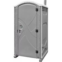
Axxis - Toilets Satellite - Free user manual and instructions
Find the device manual for free Axxis Satellite in PDF.


| Product Type | Toilet |
| Brand | Satellite |
| Model | Axxis |
| Material | Ceramic |
| Dimensions (L x W x H) | 40 x 36 x 46 cm |
| Weight | 35 kg |
| Colour | White |
| Flush Type | Dual flush push button |
| Flush Volume | 6 L / 3 L |
| Seat Included | Yes |
| Seat Shape | Round |
| Installation Type | Floor mounted |
| Water Supply | Direct from pipeline |
| Connection Size | 1/2 inch |
| Country of Origin | France |
| Certifications | NF, CE |
| Cleaning | Use mild detergent and soft cloth; avoid abrasive cleaners |
| Maintenance | Regular cleaning, check seals every 6 months |
| Safety | Ensure stable installation; do not stand on the seat |
| Spare Parts Available | Flush mechanism, seat, cover, fixing kit |
| Recyclability | Ceramic is recyclable |
| Warranty | 2 years |
| Package Contents | Toilet bowl, seat, flush button, fixing kit, manual |
| Energy Consumption | None (non-electric) |
Frequently Asked Questions - Axxis Satellite
User questions about Axxis Satellite
0 question about this device. Answer the ones you know or ask your own.
Ask a new question about this device
Download the instructions for your Toilets in PDF format for free! Find your manual Axxis - Satellite and take your electronic device back in hand. On this page are published all the documents necessary for the use of your device. Axxis by Satellite.
USER MANUAL Axxis Satellite
Assembly Instructions Axxis Portable Restroom
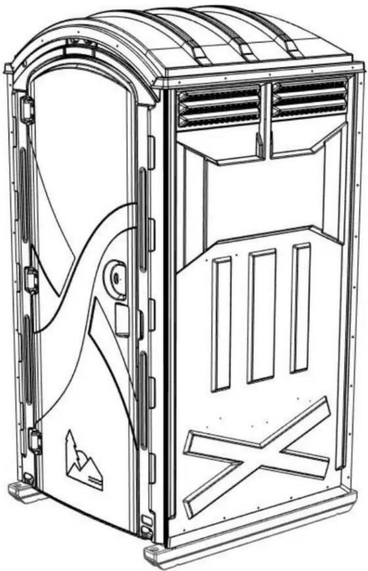
The Most Rugged Portable Restroom and Parts in the Industry!

2530 Xenium Lane North, Minneapolis, MN 55441
Telephone: 763-553-1900 Fax: 763-553-1905
800-328-3332 / www.satelliteindustries.com
INTRODUCTION
Instructions for the Axxis portable restroom
Satellite restrooms must be assembled according to approved assembly procedures. Avoid variations in assembly which could adversely affect product life.
The assembly procedures are written for assembly of single units. If assembling multiple units, considerable efficiency can be gained by working in assembly line fashion.
Tools Needed:
- Drill -#10 Drill Bit -Rivet Gun -Phillips Screw Driver or Driver bit -3/8" Nut Driver bit -1/8" Allen Wrench
HELPFUL HINTS
- Have an apron with at least two large pockets that allow the parts to be remove easily.
- Don't open up all your kit boxes. Open up only enough kit boxes to assemble the number of toilets you are currently working on. KEEP PARTS ORGANIZED.
- Use toilet paper holders for parts bins on multiple unit assembly
- The door latch can be put on at any time. It may be more efficient to have someone do this early on multiple unit assembly.
EXPLODED UNIT ASSEMBLY


**
22847 HDWE- AXXIS 3 ROLL
| 25 | 1713-699 | 1 | WASHER- 1/4 " STAINLESS FLAT |
| 24 11 | 315 58 WASHER- 3/1 | 6 RIVET STNLS | |
| 23 10 | 51-699 1 TOILET PAPER ROD FOR 3 ROLL | ||
| 22 19 | 34-699 1 SHOULDER | SCREW 1/4 " D x 2" | |
| 21 13 | 860 27 SCREW- #14 X | 1-1/2 W/WSH GOLD | |
| 20 18 | 098 1 SCREW- #10 X | 2 PN PH TAP | |
| 19 10 | 81-799 1 ROTARY DO | OR LATCH WITH LABEL | |
| 18 11 | 030 53 RIVET- #66 AAL POP | ||
| 17 22 | 543 4 RIVET- #610 AAL POP | ||
| 16 22 | 199 5 RIVET- 3/16 TRIFIX ALUM LF | ||
| 15 18 | 08-699 6 RIVET- 688 | TRI-BULB ( TRI-CLAMP) | |
| 14 10 | 38-699 1 PADLOCL (55/25) W/KEY (5253) | ||
| 13 20 | 903 1 NUT #10-24 NYLOC STLNS | ||
| 12 | 1093-699 | 2 LOCK BRACKET (AXXIS) | |
| 11 10 | 29-699 1 COAT HOOK | ||
| ITEM PART# QTY DESCRIPTION | |||
| ** 22847 1 HDWE- | AXXIS 3 ROLL |
| 10 22915 1 VENT PIPE- 4X63 AX-VN DGRY | |
| 9 22919 1 URINAL- AX-VN | DGRY |
| 8 22918 1 TANK- AX 60 GAL BLOW DGRY | |
| 7 10570 1 SEAT- TOILET TUF/FRE/LIB BLACK | |
| 6 22920 1 ROOF- AXXIS T-11 DOME NAT | |
| 5 22917 1 HOOD- PGRD AX/VN 3 ROLL DGRY | |
| 4 22849 1 DESIGN- AXXIS | FRONT ASSY |
| 3 23057 3 DESIGN- AXXIS | PANEL |
| 2 22989 4 | |
| 1 10034 1 BASE ASSY- IMPACT | |
| ITEM PART# QTY DESCRIPTION | |
Step 1: Assemble Front to base: *Tip: before assembly may help to place front on table with 44.00" height & 40.00" width or Gaylord box with pallet 44.00" height (may receive with shipment of unit parts).
Set front on table/box, outside of front up. Place base at bottom of front with front of base up & floor of base facing inward. With front facing up & pushed down against the base runners. Center front on base.

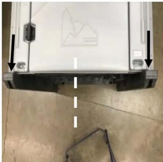
Install (4) Screws #13860 in holes on left & right side of front (door frame) at bottom, using a 3/8" Nut Driver bit (DO NOT over tighten screws, run screws in until rubber washer begins to flatten).
Remove shipping strap at bottom of front. Use Phillips screw driver or driver bit to remove 3 screws in shipping strap into bottom of front. If shipping strap is riveted on, drill out rivets using #10 Drill Bit.


Step 1 (continued): Assemble Front to base:
Open door & install (2) Screws #13860 in holes on left & right side of front (door frame) at bottom, using a 3/8" Nut Driver bit.

Step 2: Assemble Lock brackets, Coat hook, & Latch to Front: (Keep door open for Step 2 assembly).
Install Lock bracket on door with angle in Lock bracket #1093-699 toward inside of door. Use Rivets #1808-699 through holes in bracket into pre-drilled holes door frame).
Install Lock bracket on door frame with angle in Lock bracket #1093-699 toward inside of door. Use Rivets #1808-699 through holes in bracket into pre-drilled holes door frame).


Step 2: Assemble Lock brackets, Coat hook, & Latch to Front (continued):
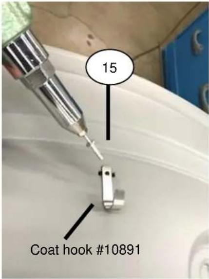
Install Coat hook #1029-699 drill at 2 dimples on inside at top of door. Rivet Coat hook in holes drilled using (2) rivets #1808-699. To install Coat hook #10891 on door inside of door. Drill between dimples at top on inside of door using #10 Drill Bit. Rivet Coat hook in hole drilled using rivet #1808-699.


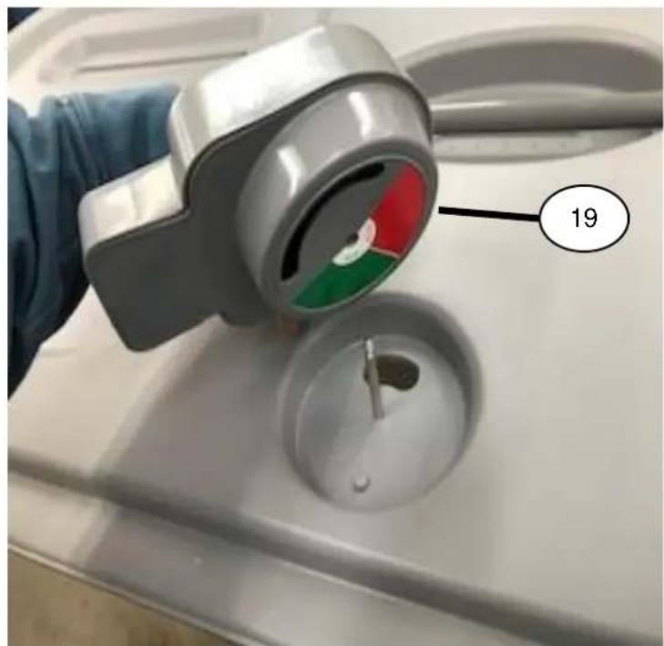
Install Rotary door latch #1081-799 on inside of door. Place Washer #1713-699 on Shoulder screw #1934-699 & insert screw in from outside of door in pre-drilled hole. Locate hole in latch & insert latch in recess area on inside of front. Decal on latch facing down towards the inside of the door.

Step 2: Assemble Lock brackets, Coat hook, & Latch to Front (continued):
With latch In position on inside of door. Place Washer #11315 on Shoulder screw & turn Nut #20903 onto shoulder screw. Tighten nut on screw using a 3/8" Nut Driver bit on nut inside of door & 1/8" Allen Wrench on screw head outside of door (do not over-tighten, latch should turn with some force but not to loose that it may turn from open to close on its own).


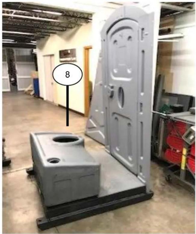
Stand up base with front & set Tank #22918 in base cradle. Install Seat-lid #10570 on tank with plastic screws & nuts (included with the seat-lid).

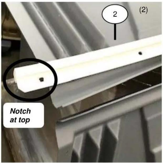
Step 3: Assemble 3 Panels: *Tip: may help to place rear panel on table or Gaylord box before assembly. Assemble side panels to rear panel. Install Corner molding #22989 between the panels (notched end of corner molding at top of panels). Fasten panels, start in middle of panels use (16) Rivets #11030 and (16) Washers #11315 (rivet from side panel). Bottom hole on panels use longer rivet (2) Rivets #22543 & (2) Washers #11315. Repeat sequence to assemble other side panel to rear panel.


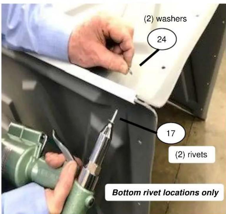
Step 4: Assemble 3 Panels to Front: Pull 3 assembled side panels onto base & front assembly. Install corner molding # #22989 between the panels & front (notched end of corner molding at top of panels). Fasten panels, start in middle of panels use (16) Rivets #11030 and (16) Washers #11315 (rivet from side panel). Bottom hole on panels use longer rivet, (2) Rivets #22543 & (2) Washers #11315. Repeat sequence to assemble other side panel to front panel.


Step 5: Assemble 3 Panels to base: Make sure the spacing between the panel & top of runner at back of side panel is even with the front of the side panel on base. Then align center hole in panel with center bump on top of the base runner. Install Screw #13860 in center hole of panel using of 3/8" Nut Driver bit. (DO NOT over tighten screws, run screws in until rubber washer begins to flatten).

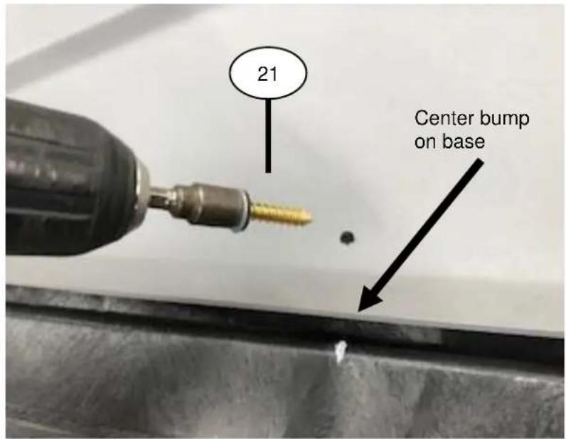
Install Screws #13860 in remaining 4 holes in panel into base using of 3/8" Nut Driver bit. Repeat sequence to assemble other side panel to base. Install (5) Screws #13860 in 5 holes in rear panel into base using of 3/8" Nut Driver bit.

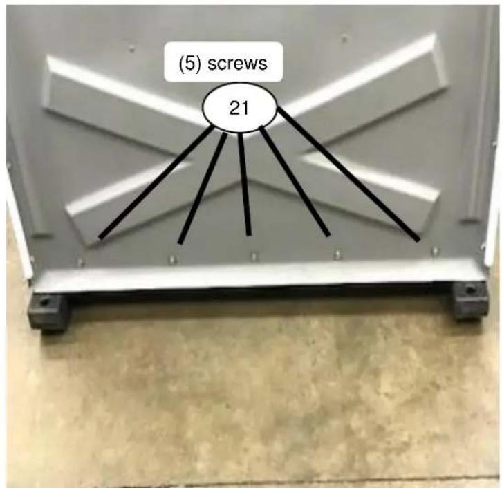
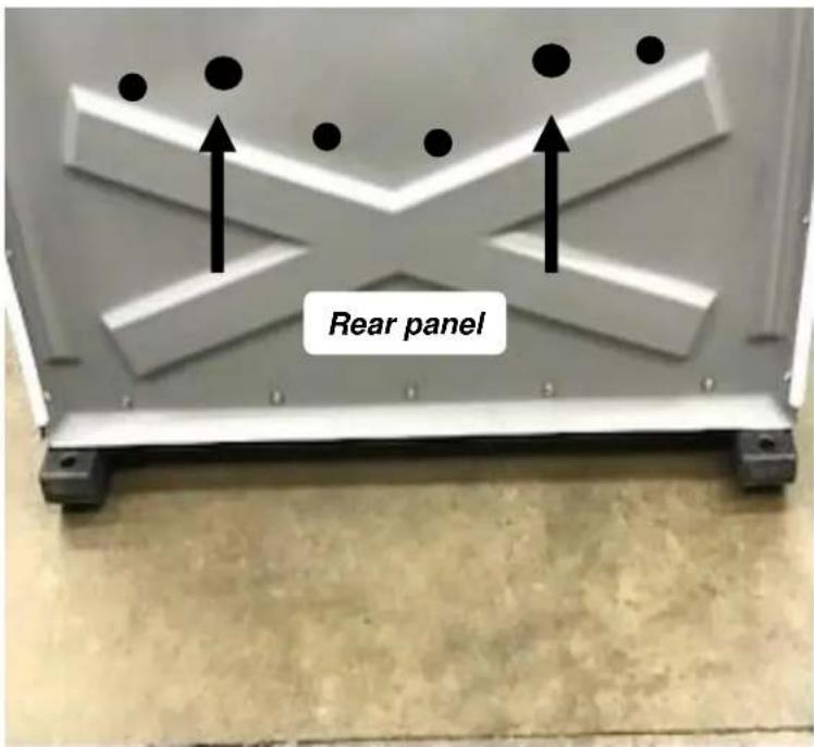
Step 6: Assemble Tank to panels: With tank level in base & down tight to base (have someone sit on tank). Locate 2 dimples in lower rear section of side panel. Install (2) Screws #13860 through dimples into tank using of 3/8" Nut Driver bit (DO NOT over tighten screws, run screws in until rubber washer begins to flatten). Repeat sequence to assemble other side panel to tank.


Locate 2 dimples in lower rear section of rear panel. Install (2) Screws #13860 through dimples into tank using of 3/8" Nut Driver bit.

Step 7: Assemble Urinal to panel: Place Urinal #22919 drain tube in pre-drilled hole in left front corner of tank. If tank does not have a urinal hole in left front corner, use a 1.00" hole saw at drill point in tank. Hold urinal level against the left panel & transfer drill in center of recessed tabs at top of urinal (left & right side) through panel using #10 Drill Bit. Fasten urinal to panel, use (2) Rivets #11030 inside through holes drilled in urinal / panel & (2) Washers #11315 outside on panel.

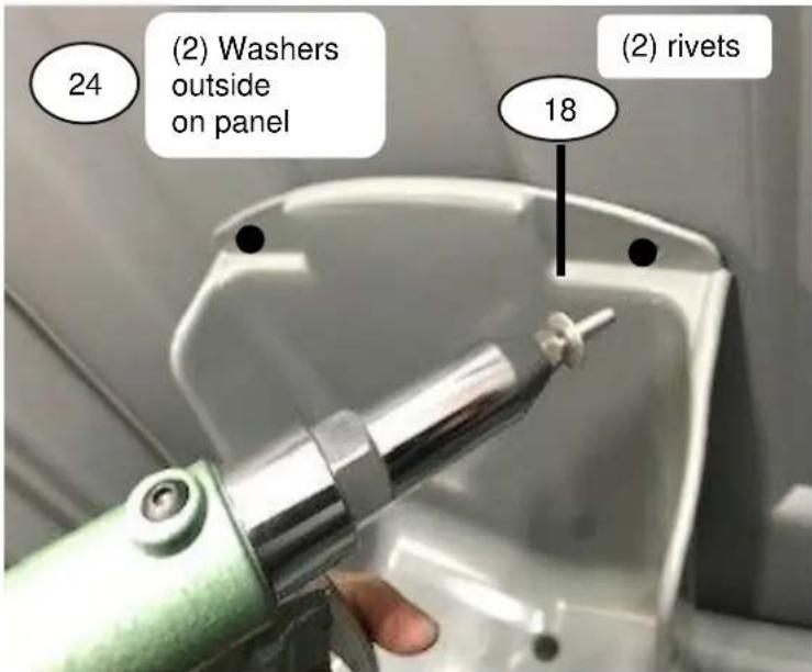
Step 8: Assemble Paperguard hood to panel: Drill out 2 dimples in top recess tabs in PaperGuard hood #22917 using #10 Drill Bit. Drill out 2 dimples in right panel using #10 Drill Bit.

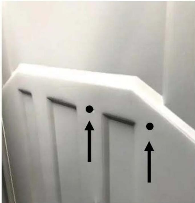
Step 8: Assemble Paperguard hood to panel (continued): Install toilet paper rod #1051-699 in Paper guard hood from left to right end with hole in first. Place Padlock #1038-699 on end hole (out from right side of Paper guard hood). Fasten Paper guard hood to panel, use (2) Rivets #11030 inside through holes drilled in top of Paper guard hood into holes in panel & (2) Washers #11315 outside on panel.


Drill out in center of bottom tabs in PaperGuard hood through panel using #10 Drill Bit. Fasten urinal to panel, use (2) Rivets #11030 inside through holes drilled in urinal / panel & (2) washers #11315 outside on panel.
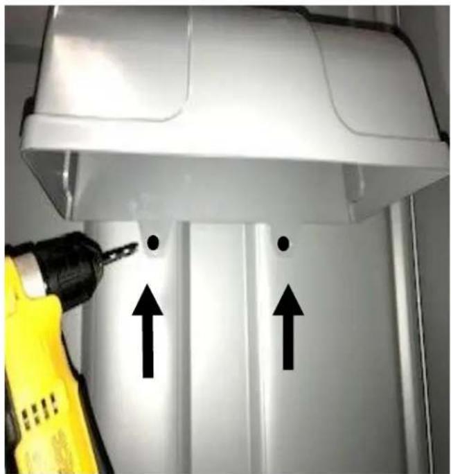

Step 9: Assemble Roof to panels & front: Place roof on panels & front as shown. Push roof towards back of cabana so it is tight against front door frame. Drill through 5 holes in roof (5 dimples if roof has no holes) through front (only through first wall of door frame) using #10 Drill Bit. Fasten roof to front, use (5) Rivets #22199.T-11 roof shown, T-22 roof is installed the same way.

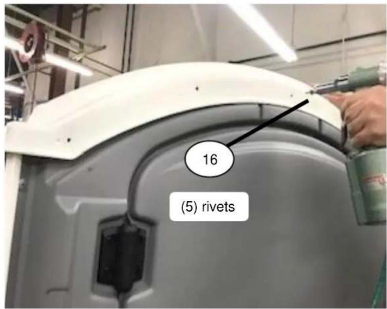
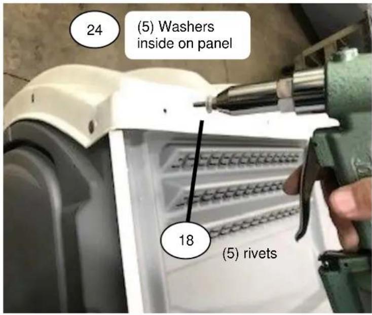
Drill through 5 holes in roof (5 dimples if roof has no holes & panel has no holes) through rear panel using #10 Drill Bit. Fasten roof to rear panel using (5) Rivets #11030 outside on roof & (5) Washers #11315 inside on panel.
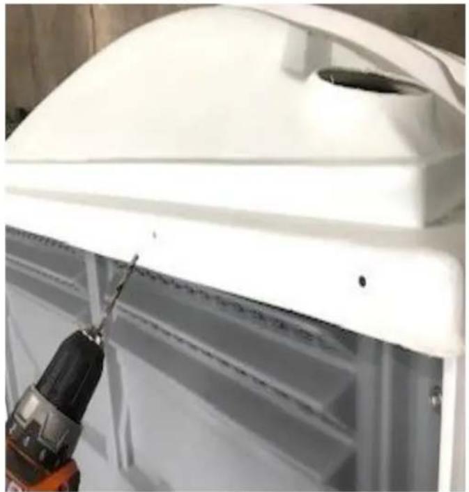

Step 9: Assemble Roof to panels & front (continued): Drill through 5 holes in roof (5 dimples if roof has no holes & panel has no holes) through side panel using #10 Drill Bit. Fasten roof to side panel using (5) Rivets #11030 outside on roof & (5) Washers #11315 inside on panel. Repeat sequence to assemble roof to other side panel.

Step 10: Assemble Vent pipe to roof & tank: Insert Vent pipe #22916 into hole in rear left corner of roof & down into collar on rear left corner of tank. Make sure vent pipe is completely down in tank. Fasten Vent pipe to tank in recess with Screw #18098 using Phillips Screw Driver or Driver bit.


2530 Xenium Lane North, Minneapolis, MN 55441
Telephone: 763-553-1900 Fax: 763-553-1905
800-328-3332 / www.satelliteindustries.com

Brand : Satellite
Model : Axxis
Category : Toilets