
FT121LDP - Smoke detector Dahua Technology - Free user manual and instructions
Find the device manual for free FT121LDP Dahua Technology in PDF.


| Product Type | Flame Detection Network Camera (Smoke Detector) |
| Brand | Dahua Technology |
| Model | FT121LDP |
| Power Supply | 12 VDC or PoE (IEEE 802.3af) |
| Power Consumption | < 5 W (typical) |
| Dimensions | Approximately 100 mm × 100 mm × 50 mm (without bracket) |
| Weight | Approximately 150 g (net) |
| Network Interface | 1× RJ-45 10/100 Base-T |
| Alarm I/O | 1 input / 1 output (NO/NC configurable) |
| Detection Method | Flame detection via image analysis (CMOS sensor) |
| Operating Temperature | -10 °C to +55 °C |
| Operating Humidity | 10% to 90% (non-condensing) |
| Ingress Protection | IP67 (with waterproof connector installed) |
| Mounting | Wall or ceiling mount (bracket included) |
| Configuration | Via web interface or ConfigTool software |
| Firmware Upgrade | Via web interface or ConfigTool |
| Cleaning | Wipe with soft dry cloth; use mild detergent for stubborn stains. Do not use volatile solvents. |
| Safety | Complies with local electrical safety codes. ES1 power supply required. |
| Spare Parts | Contact manufacturer for replacement parts; only use provided accessories. |
| Warranty | Standard manufacturer warranty (check product documentation) |
Frequently Asked Questions - FT121LDP Dahua Technology
User questions about FT121LDP Dahua Technology
0 question about this device. Answer the ones you know or ask your own.
Ask a new question about this device
Download the instructions for your Smoke detector in PDF format for free! Find your manual FT121LDP - Dahua Technology and take your electronic device back in hand. On this page are published all the documents necessary for the use of your device. FT121LDP by Dahua Technology.
USER MANUAL FT121LDP Dahua Technology
Flame Detection Network Camera
Quick Start Guide

natural_image
Abstract geometric composition with gray and red color blocks (no text or symbols)Foreword
General
This manual introduces the functions, configuration, general operation, and system maintenance of flame detection network camera.
Safety Instructions
The following signal words might appear in the manual.
| Signal Words | Meaning |
 WARNING WARNING | Indicates a medium or low potential hazard which, if not avoided, could result in slight or moderate injury. |
 CAUTION CAUTION | Indicates a potential risk which, if not avoided, could result in property damage, data loss, lower performance, or unpredictable result. |
| [K3WS]NOTE | Provides additional information as the emphasis and supplement to the text. |
Revision History
| Version | Revision Content | Release Date |
| V1.0.0 | First release. | October 2022 |
Privacy Protection Notice
As the device user or data controller, you might collect the personal data of others such as their face, fingerprints, and license plate number. You need to be in compliance with your local privacy protection laws and regulations to protect the legitimate rights and interests of other people by implementing measures which include but are not limited: Providing clear and visible identification to inform people of the existence of the surveillance area and provide required contact information.
About the Manual
- The manual is for reference only. Slight differences might be found between the manual and the product.
- We are not liable for losses incurred due to operating the product in ways that are not in compliance with the manual.
- The manual will be updated according to the latest laws and regulations of related jurisdictions. For detailed information, see the paper user's manual, use our CD-ROM, scan the QR code or visit our official website. The manual is for reference only. Slight differences might be found between the electronic version and the paper version.
- All designs and software are subject to change without prior written notice. Product updates might result in some differences appearing between the actual product and the manual. Please contact customer service for the latest program and supplementary documentation.
- There might be errors in the print or deviations in the description of the functions, operations and technical data. If there is any doubt or dispute, we reserve the right of final explanation.
- Upgrade the reader software or try other mainstream reader software if the manual (in PDF format) cannot be opened.
- All trademarks, registered trademarks and company names in the manual are properties of their respective owners.
- Please visit our website, contact the supplier or customer service if any problems occur while using the device.
- If there is any uncertainty or controversy, we reserve the right of final explanation.
Important Safeguards and Warnings
Electrical Safety
- All installation and operation shall conform to your local electrical safety codes.
- The power supply must conform to the requirements of ES1 in IEC 62368-1 standard and no higher than PS2. Note that power supply requirements are subject to the device label.
- Make sure that the power supply is correct before operating the device.
- A readily accessible disconnecting device shall be incorporated in the building installation wiring.
- Prevent the power cable from being trampled or pressed, especially the plug, power socket and the junction extruded from the device.
Environment
- Do not aim the device at strong light to focus, such as lamp light and sun light; otherwise it might cause over brightness or light marks, which are not device malfunctions, and affect the longevity of Complementary Metal-Oxide Semiconductor (CMOS).
- Do not place the device in a damp, dusty extremely hot or cold environment, or the locations with strong electromagnetic radiation or unstable lighting.
- Keep the device away from any liquid to avoid damage to the internal components.
- Keep the indoor device away from rain or damp to avoid fire or lightning.
- Keep sound ventilation to avoid heat accumulation.
- Transport, use and store the device within the range of allowed humidity and temperature.
- Heavy stress, violent vibration or water splash are not allowed during transportation, storage and installation.
- Pack the device with standard factory packaging or the equivalent material when transporting the device.
- Install the device in the location where only the professional staff with relevant knowledge of safety guards and warnings can access. The accidental injury might happen to the non-professionals who enter the installation area when the device is operating normally.
Operation and Daily Maintenance
- Do not touch the heat dissipation component of the device to avoid scald.
- Carefully follow the instructions in the manual when disassembling operation about the device; otherwise, it might cause water leakage or poor image quality due to unprofessional operations. Make sure that the gasket ring is flat and properly installed in the groove before installing the cover. Contact after-sales service for desiccant replacement if there is condensed fog on the lens after unpacking or when the desiccant turns green (Not all models are included with the desiccant).
- We recommend using the device together with lightning arrester to improve lightning protection effect.
• We recommend grounding the device to enhance reliability. - Do not touch the image sensor (CMOS) directly. Dust and dirt could be removed with air blower, or you can wipe the lens gently with soft cloth that is moistened with alcohol.
- You can clean the device body with soft dry cloth, and for stubborn stains, use the cloth with
mild detergent. To avoid possible damage on device body coating which could cause performance decrease, do not use volatile solvent such as alcohol, benzene, diluent to clean the device body, nor can strong, abrasive detergent be used.
- Dome cover is an optical component. Do not touch or wipe the cover with your hands directly during installation or operation. For removing dust, grease or fingerprints, wipe gently with moistened oil-free cotton with diethyl or moistened soft cloth. You can also remove dust with an air blower.

WARNING
- Strengthen the protection of network, device data and personal information by adopting measures which include but not limited to using strong password, changing password regularly, upgrading firmware to the latest version, and isolating computer network. For some devices with old firmware versions, the ONVIF password will not be changed automatically along with changing the system password, and you need to upgrade the firmware or manually change the ONVIF password.
- Use standard components or accessories provided by manufacturer and make sure that the device is installed and maintained by professional engineers.
- Do not expose the surface of the image sensor to laser beam radiation in an environment where a laser beam device is used.
- Do not provide two or more power supply sources for the device unless otherwise specified. A failure to follow this instruction might cause damage to the device.
Table of Contents
Foreword....
Important Safeguards and Warnings....III
1 Introduction....1
1.1 Cable....1
1.2 Connecting Alarm Input/Output 2
2 Network Configuration....4
2.1 Initializing Device....4
2.2 Changing Device IP Address....6
2.3 Logging in to Web Interface....7
3 Installation....8
3.1 Packing List....8
3.2 Dimensions....8
3.3 Installing Camera....9
3.3.1 Installation Method....9
3.3.2 Installation Direction....9
3.3.3 Detaching the Device....9
3.3.4 Attaching Device....9
3.3.5 (Optional) Installing Waterproof Connector....10
3.3.6 Adjusting Lens Angle....11
1 Introduction
1.1 Cable

Waterproof all the cable joints with insulating tape and waterproof tape to avoid short circuit and water damage. For the detailed operation, see FAQ manual.
Figure 1-1 Cables

Table 1-1 Cable information
| No. | Port name | Description |
| 1 | Power input | Inputs 12 VDC power. Be sure to supply power as instructed in the manual. Device damage might occur if power is not supplied correctly. Device damage might occur if power is not supplied correctly. |
| 2 | LAN | Connects to network with network cable.Provides power to the device with PoE. PoE is available on select models. PoE is available on select models. |
| 3 | Alarm I/O | Includes alarm signal input and output ports, and the number of I/O ports might vary on different devices. For detailed information, see Table 1-2. |
Table 1-2 Alarm information
| Port | Port Name | Description |
| Alarm I/O | ALARM_OUT | Outputs alarm signal to alarm device. |
| ALARM_OUT_GND | When connecting to alarm device, only the ALARM_OUT port and ALARM_OUT_GND port with the same number can be used together. | |
| ALARM_IN | Receives the switch signal of external alarmsource. | |
| ALARM_IN_GND | Connect different alarm input devices to the same ALARM_IN_GND port. |
1.2 Connecting Alarm Input/Output
The camera can connect to external alarm input/output device through digital input/output port.

Alarm input/output is available on select models.
Step 1 Connect alarm input device to the alarm input end of the I/O port.
Device collects different states of alarm input port when the input signal is idling and being grounded.
• Device collects logic "1" when input signal is connected to +3 V to +5 V or idling.
• Device collects logic "0" when input signal is grounded.
Figure 1-2 Alarm input

flowchart
graph LR
    A["Ground Wire"] --> B["Alarm Input"]
    B --> C["Flame Detection Network Camera"]
    C --> D["Collecting"]
Step 2 Connect alarm output device to the alarm output end of the I/O port. The alarm output is open-drain output, which works in the following modes.
- Mode A: Level application. Alarm outputs high and low level, and the alarm outlet is OD, which requires external pull-up resistance (10 K Ohm typical) to work. The maximum external pull-up level is 12 V, maximum port current is 300 mA and the default output signal is high-level (external pull-up voltage). The default output signal switches to low-level when there is alarm output (As long as the operating current is below 300 mA, the output low-level voltage is lower than 0.8 V).
- Mode B: Switch application. Alarm output is used to drive external circuit, the maximum voltage is 12 V and the maximum current is 300 mA. If the voltage is higher than 12 V, please use an additional electric relay.
Figure 1-3 Alarm output

flowchart
graph TD
    A["External Device"] --> B["Power"]
    B --> C["Resistance"]
    C --> D["Input"]
    D --> E["Ground Wire"]
    E --> F["Alarm Output"]
    F --> G["Max 12V, 300mA"]
    G --> H["Output"]
    I["Flame Detection Network Camera"] --> H

Step 3 Log in to web interface, and configure alarm input and alarm output in alarm setting.
- The alarm input on the web interface is corresponding to the alarm input end of the I/O port. There will be high level and low level alarm signal generated by the alarm input device when alarm occurs, set the input mode to "NO" (default) if the alarm input signal is logic "0" and to "NC" if the alarm input signal is logic "1".
- The alarm output on the web interface is corresponding to the alarm output end of the device, which is also alarm output end of the I/O port.
2 Network Configuration
Device initialization and IP setting can be finished with the "ConfigTool" or on web interface. For more information, see web operation manual.

- Device initialization is available on select models, and it is required at first-time use and after device is being reset.
- Device initialization is available only when the IP addresses of the device (192.168.1.108 by default) and the PC stay in the same network segment.
- Plan usable network segment properly to connect the device to the network.
• The following figures and interfaces are for reference only.
2.1 Initializing Device
Step 1 Double-click ConfigTool.exe to open the tool.
Step 2


Step 3
Click Search Setting.
Figure 2-1 Setting

Step 4 Select the searching way.
• Current Segment Search (default)
Select the Current Segment Search checkbox. Enter the username in the Username box and the password in the Password box. The system will search devices accordingly.
- Other Segment Search
Select the Other Segment Search checkbox. Enter IP address in the Start IP box and End IP box respectively. Enter username and password. The system will search the devices accordingly.

- If you select the Current Segment Search checkbox and the Other Segment Search checkbox together, the system searches for devices under both conditions.
- Enter username and the password when you want to change IP, configure the system, update the device, restart the device, and more.
Step 5 Click OK
Step 6 Select one or several devices in uninitialized status, and then click Initialize.
Step 7 Select the devices to be initialized, and then click Initialize.

- If you do not provide the linked information for password reset, you can reset the password only through XML file.
- When initializing multiple devices, ConfigTool initializes all devices based on the password reset mode of the first selected device.
Figure 2-2 Password setting

Step 8 Set and confirm the password of the devices, then enter a valid email address, and then click Next
Figure 2-3 Device initialization
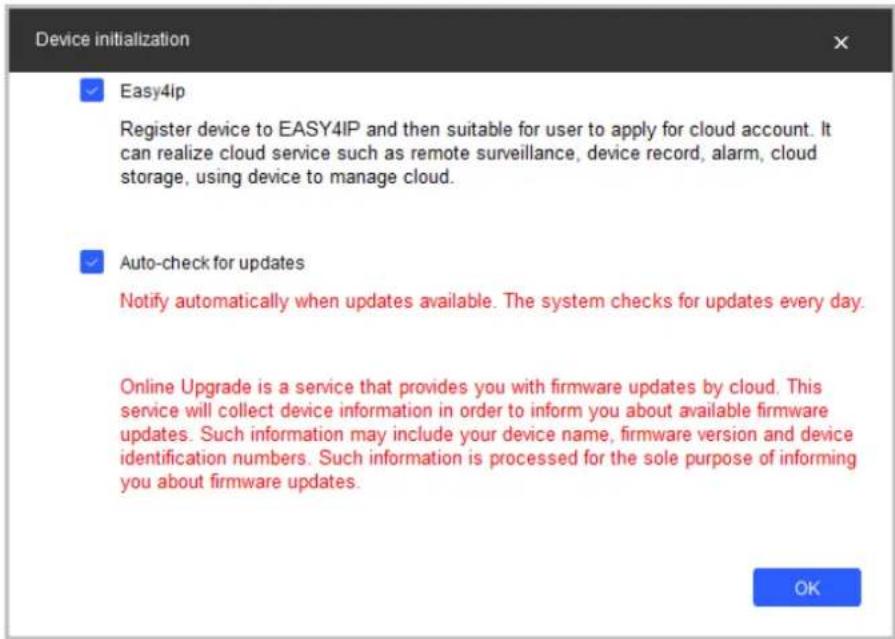
Step 9 Select Easy4ip or select Auto-check for updates according to the actual needs. If neither, leave them unselected.
Step 10 Click OK to initialize the device. Click the success icon (√) or the failure icon (▲) for the details.
Step 11 ClickFinish.
2.2 Changing Device IP Address
- You can change IP address of one or multiple devices at one time. This section is based on changing IP addresses in batches.
- Changing IP addresses in batches is available only when the corresponding devices have the same login password.
Step 1 Do Step1 to Step5 in "2.1 Initializing Device" to search devices in your network segment.

After clicking Search setting enter the username and password, and make sure that they are the same as what you set during initialization; otherwise there will be wrong password notice.
Step 2 Select the devices whose IP addresses need to be modified, and then click Batch Modify IP.
Figure 2-4 Change IP address

Step 3 Select Static mode, and then enter start IP, subnet mask, and gateway.

- IP addresses of multiple devices will be set to the same if you select the Same IP checkbox.
- If DHCP server is available in the network, devices will automatically obtain IP addresses from DHCP server when you select DHCP.
Step 4 Click OK
2.3 Logging in to Web Interface
Step 1 Open browser, enter the IP address of the device in the address bar, and then press the Enter key.
If the setup wizard is displayed, finish the settings as instructed.
Step 2 Enter the username and password in the login box, and then click Login
Step 3 For the first-time login, click Click Here to Download Plugin, and then install the plugin as instructed.
The main interface is displayed when the installation is finished.
3 Installation
3.1 Packing List

The tool required for the installation such as electric drill is not provided in the package.

3.2 Dimensions
![114.8 [4.52] Ø109.9 [Ø4.33] 90.1 [3.55]](/content/2026/05/1060521/images/5685d46eb78fa0b154b33aa1cad6b8e3e8a515c4d1eea69aafa84cc908299b68.jpg)
3.3 Installing Camera
3.3.1 Installation Method
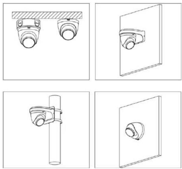
3.3.2 Installation Direction

natural_image
Technical line drawing of a mechanical device with no visible text or symbols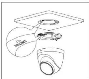
3.3.3 Detaching the Device


natural_image
Diagram showing a hand holding a circular object with a magnified view of its top surface, no text or symbols present.3.3.4 Attaching Device

Make sure that the mounting surface is strong enough to hold at least three times the weight of the camera and bracket.
Cable going through the mounting surface

Cable going through the side cable tray

3.3.5 (Optional) Installing Waterproof Connector
This part is needed only when there is waterproof connector come with the device and the device is used outdoor.
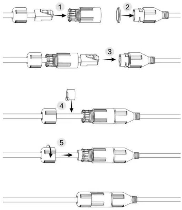
flowchart
graph TD
    A["Step 1: Connector"] --> B["Step 2: Connector"]
    B --> C["Step 3: Connector"]
    C --> D["Step 4: Connector"]
    D --> E["Step 5: Connector"]
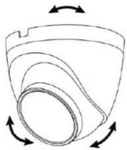
3.3.6 Adjusting Lens Angle
Figure 3-8 Adjust lens angle
natural_image
Diagram of a curved mechanical component with rotational arrows indicating motion (no text or symbols)ENABLING A SAFER SOCIETY AND SMARTER LIVING
- Flame Detection Network Camera
- Quick Start Guide
- Foreword
- General
- Safety Instructions
- Privacy Protection Notice
- About the Manual
- Important Safeguards and Warnings
- Electrical Safety
- Environment
- Operation and Daily Maintenance
- WARNING
- Table of Contents
- Foreword....
- Important Safeguards and Warnings....III
- Introduction....1
- Network Configuration....4
- Installation....8
- Introduction
- Cable
- Connecting Alarm Input/Output
- Network Configuration
- Initializing Device
- Changing Device IP Address
- Logging in to Web Interface
- Installation
- Packing List
- Dimensions
- Installing Camera
- Installation Method
- Installation Direction
- Detaching the Device
- Attaching Device
- Cable going through the mounting surface
- Cable going through the side cable tray
- (Optional) Installing Waterproof Connector
- Adjusting Lens Angle
Brand : Dahua Technology
Model : FT121LDP
Category : Smoke detector