
ADT 906-2 S - Range hood Arçelik - Free user manual and instructions
Find the device manual for free ADT 906-2 S Arçelik in PDF.


| Product Type | Range Hood |
| Brand | Arçelik |
| Model | ADT 906-2 S |
| Width | 900 mm |
| Depth | 500 mm |
| Height (Telescopic Chimney) | 160 - 1100 mm |
| Net Weight | 18 kg |
| Power Supply | 220-240 V ~ 50 Hz |
| Motor Power | 250 W |
| Maximum Extraction Rate | 650 m³/h |
| Noise Level (max speed) | 66 dB(A) |
| Number of Speeds | 3 |
| Controls | Push buttons |
| Lighting | 2 x 3 W LED |
| Grease Filter Type | Aluminum mesh, washable |
| Charcoal Filter (optional) | Yes, for recirculation mode |
| Duct Diameter | 150 mm |
| Energy Class | A+ |
| Annual Energy Consumption | 45 kWh |
| Warranty | 2 years |
| Material | Stainless steel |
| Installation Type | Wall-mounted |
Frequently Asked Questions - ADT 906-2 S Arçelik
User questions about ADT 906-2 S Arçelik
0 question about this device. Answer the ones you know or ask your own.
Ask a new question about this device
Download the instructions for your Range hood in PDF format for free! Find your manual ADT 906-2 S - Arçelik and take your electronic device back in hand. On this page are published all the documents necessary for the use of your device. ADT 906-2 S by Arçelik.
USER MANUAL ADT 906-2 S Arçelik
natural_image
Icon of crossed wrench and screwdriver tools (no text or symbols)TR / EN
1
2
natural_image
Pure diagram of a vertical structure with an arrow indicating upward and downward motion, no text or symbols present.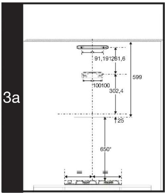
6
7
natural_image
Line drawing of a kitchen appliance with four fans and a stove on a counter, no text or symbols present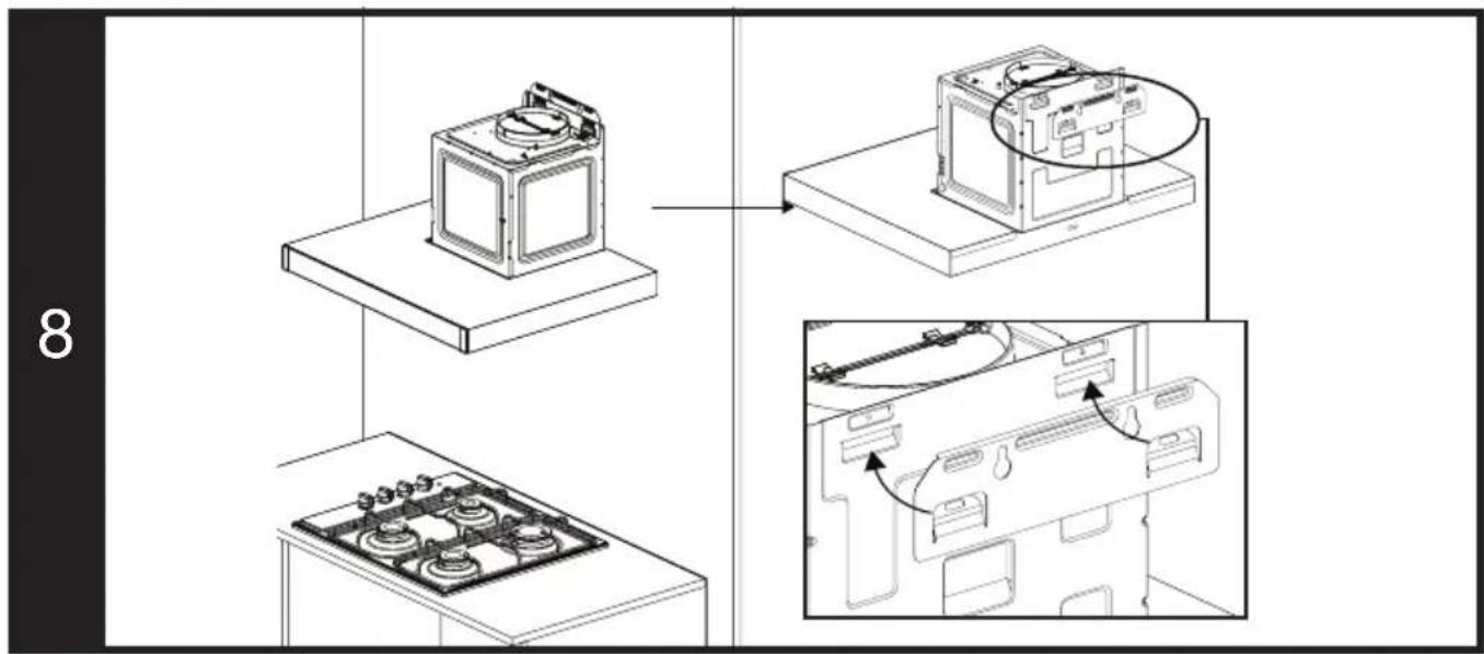
11
natural_image
Technical line drawing of a mechanical assembly with no visible text or symbols12
13
natural_image
Technical line drawing of a mechanical assembly with a coiled spring mounted on a base (no text or symbols)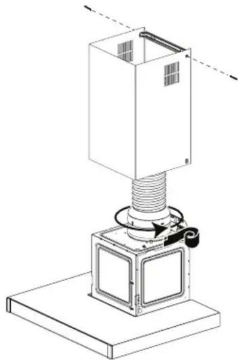
natural_image
Technical line drawing of a mechanical assembly with a coiled spring mounted on a base (no text or symbols)14
natural_image
Isometric line drawing of a tall industrial or warehouse structure with a base platform and window-like cutouts (no text or symbols)EN - Safety instruction
- Product must be installed by a qualified person in accordance with the regulations in force. The manufacturer shall not be held responsible for damages arising from procedures carried out by unauthorized persons which may also void the warranty.
- Preparation of location and electrical installation for the product is under customer's responsibility. Before calling the Authorized Service, make sure that the electrical installation is suitable. If not, call a qualified electrician to make the necessary arrangements.
- The product must be installed in accordance with all local electrical regulations.
- Before installing the product, remove all the materials and documents in it and visually check if the product has any defects on it. If so, do not have it installed.
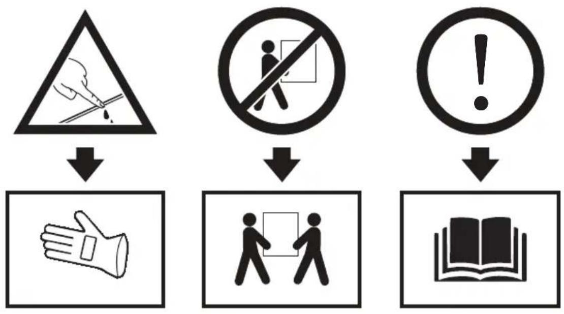
- The product is heavy, carry the product with at least two people
- Disconnect electrical connections in the area to be installed before installation.
- Failure to install screws or fixing equipment in accordance with the instructions may result in electrical hazard.
- There may be sharp surfaces on product parts. Always wear protective gloves for installation.
- If the product is not fastened sufficiently, there may be a risk of falling. Make sure that all fixings are securely fastened.
- The width of the hood should be at least equal to the width of your hob.
- The dimensions given in the installation diagrams are in mm.
• The air to be exhausted with the hood should
not be given to a chimney used by other devices burning gas or other fuels. (Not only for devices that return air to the room)
- Regulations regarding the exhaust of air must be followed.
Installing the product
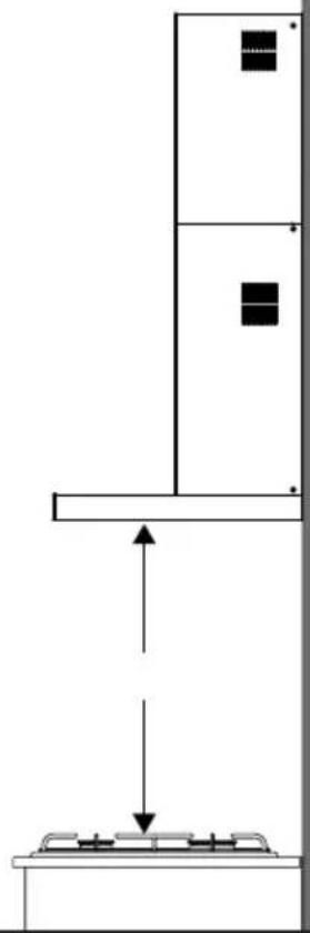
Product dimensions and security measures (Picture 1-2)
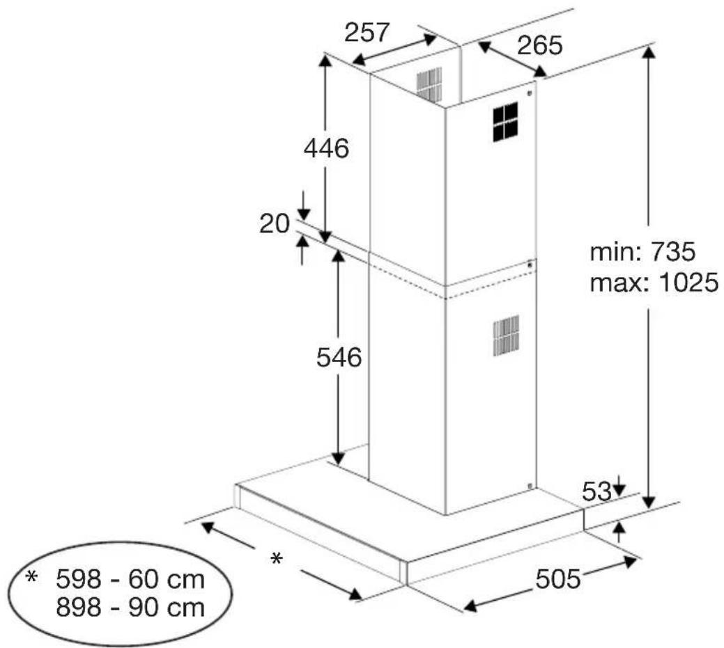
- Pay attention to product dimensions. Check the suitability for your furniture. (Picture 1)
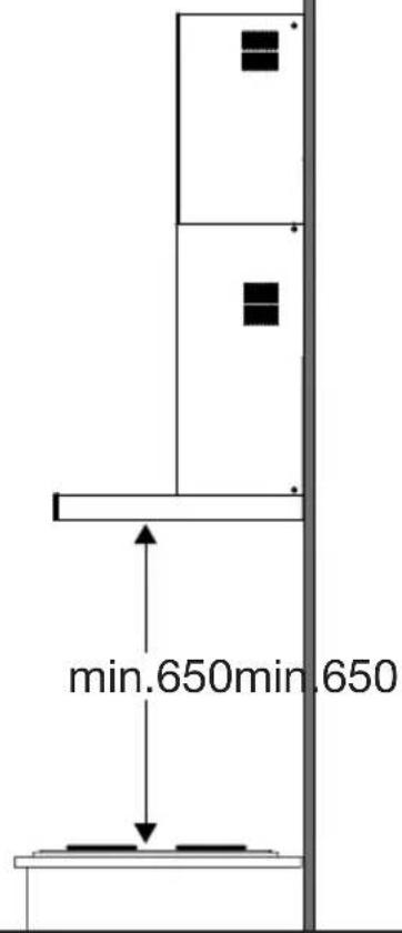
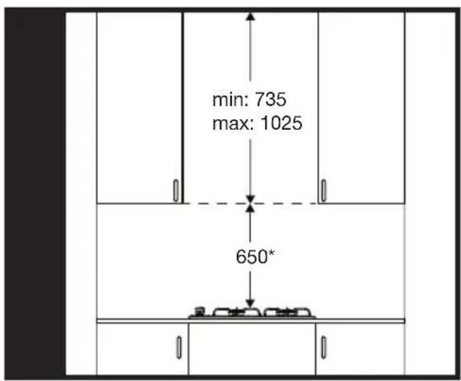
- The height between the lower surface of your hood and the upper surface of the hob should not be less than 650 mm for gas hobs, 650 mm for electrical hobs. (Picture 2)
Control and preparation of the wall to be installed
- The wall on which the product will be installed must be in an upright and flat position that has the carrying power of the product.
- There must be no water, electricity and gas connections on the wall to be installed and around the holes to be drilled.
Connecting the appliance to the electricity supply
- Manufactured with 2-track power cable, this device must be connected to the mains by an electrical switch with at least 3mm clearance between bipolar contact leads. Have the electrical connections done by a qualified electrician.
- Before starting any work on the electrical installation, disconnect the product from the mains supply. There is the risk of electric shock!
- The product must be connected to the mains supply only by an authorised and qualified person. The product's warranty period starts only after correct installation. Manufacturer shall not be held responsible for damages arising from procedures carried out by unauthorised persons.
- Install your appliance so that you can reach the power connection (plug, outlet) easily after installation.
- If your product has been produced with plug, do not cut the plug to connect to electrical supply during installation. Otherwise, the warranty becomes void and the safety risks may happen for users.
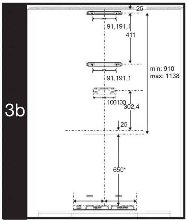
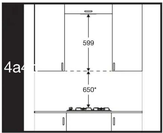
Installation dimensions and details (Picture 3-4))
- The dimensions in which the product can be installed with a double chimney are shown in picture 3b.
- If you are going to install it with a double chimney, the measure from the required clearance distance above the hob to your furniture should be in the range of 910-1138 mm. (Picture 4b)
- If you are going to install it with a single chimney, the measure from the required clearance distance above the hob to your furniture should be 748 mm. (Picture 3a-4a) For the installation with one chimney, use the upper chimney which has ventilation hole.
Assembling the product fixing parts (Picture 5-6-7)
Your product is described over double chimney sheet assembly sampling.
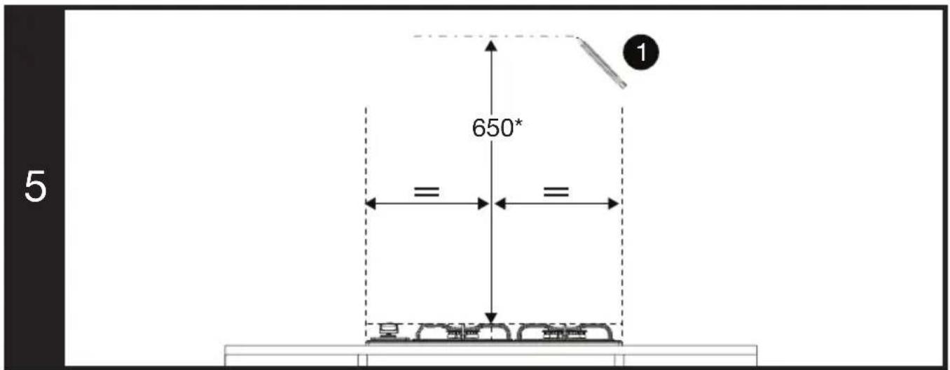
- Center your hob and draw a vertical axis line on the wall.
- Draw a horizontal reference line measuring 650 mm from the top of your hob. (Picture 5)
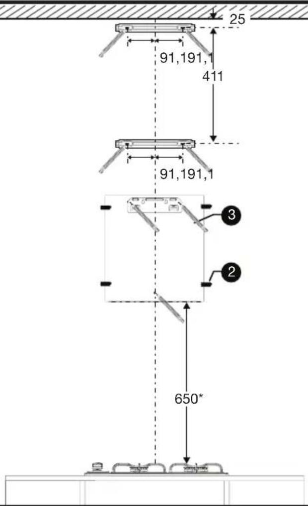
- Center the template given with the product on the reference point you have drawn, paste it on the wall and mark the holes in the template with a pencil. (Picture 6)
- Mark the holes for the chimney fixing parts according to the dimensions given in picture 6 from the top of your furniture or ceiling.
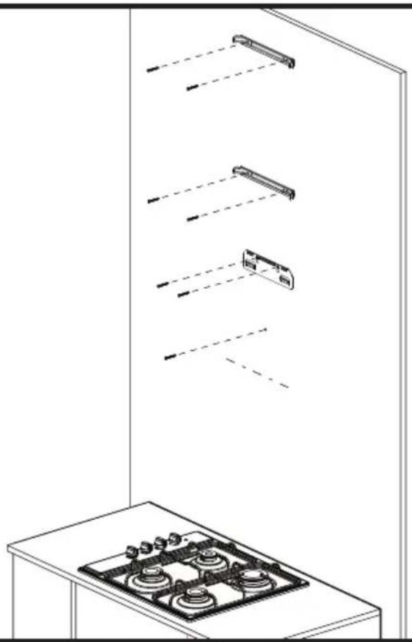
- Fix the hood fixing part and chimney fixing parts to the wall as shown in picture 7.
Hanging, aligning and fixing the hood (Picture 8-9-10-11)
- Hang your hood on the hood fixing part that you have fixed to the wall. (Picture 8)
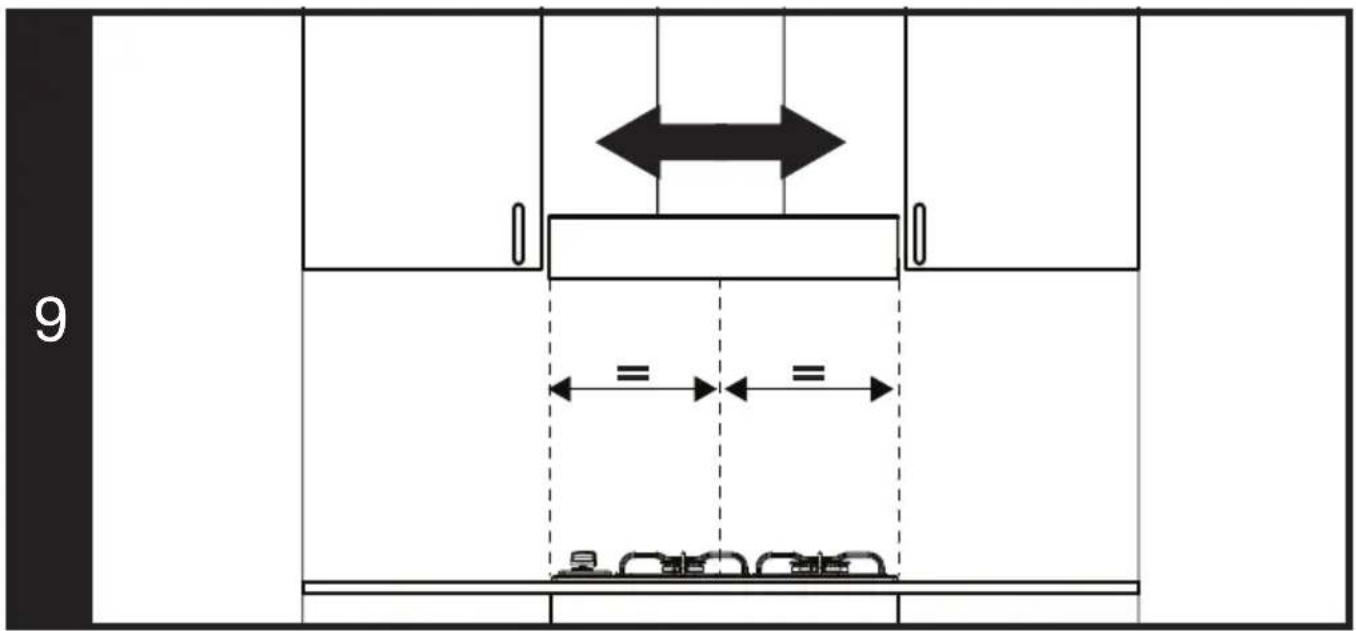
- Align your hob in a central position by sliding the hood left and right on the fixing parts. (Picture 9)
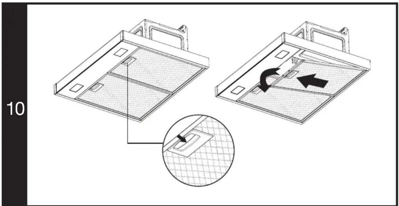
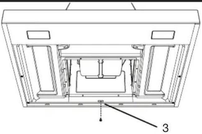
- Remove the aluminum filters as shown in picture 10.
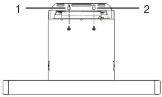
- Fix your hood on the hood fixing and wall part as shown in picture 11.
- Fit the aluminum filters into its place.
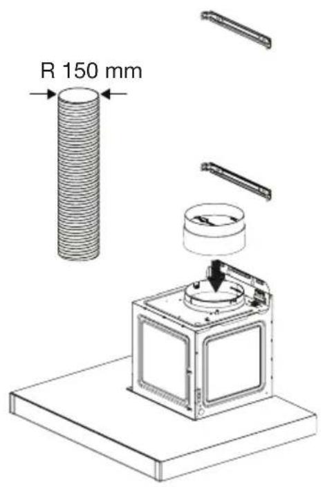
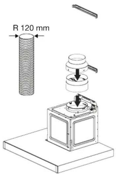
- Fitting the chimney outlet pipe (Picture 12)
- As shown in the picture 12, place the cover that prevents reversed air flow to the chimney outlet.
- If your chimney connection pipe's diameter is 150 mm place the chimney outlet pipe onto the cover
- If your chimney connection pipe's diameter is 120 mm; Place the chimney outlet pipe after placing the connection adapter on the cover.
- Properly insulate the connection points.
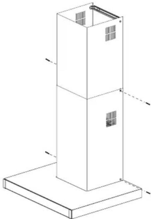
Fixing the chimney sheets (Picture 13-14)
- If your chimney connection pipe's diameter is 120 mm; Stick the supplied tape around the junction of the connection adapter and the air outlet slot. (Picture 13)
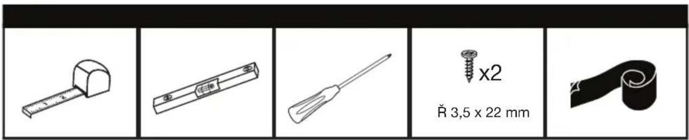
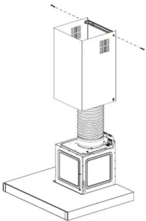
- Fix the upper chimney sheet to the upper chimney fixing part with 2 screws from the sides of the curves. (Picture 13)
- Fix the lower chimney sheet to the lower chimney fixing part with 2 screws from the curves on the sides. (Picture 14)
- Complete the installation by fixing the lower chimney sheet with 2 screws from the bottom hole circles on the hood. (Picture 14)
Final check
- Control your hood and lamp by operating it as described in the user manual.
- EN - Safety instruction
- Installing the product
- Product dimensions and security measures (Picture 1-2)
- Control and preparation of the wall to be installed
- Connecting the appliance to the electricity supply
- Installation dimensions and details (Picture 3-4))
- Assembling the product fixing parts (Picture 5-6-7)
- Hanging, aligning and fixing the hood (Picture 8-9-10-11)
- - Fitting the chimney outlet pipe (Picture 12)
- Fixing the chimney sheets (Picture 13-14)
- Final check
Brand : Arçelik
Model : ADT 906-2 S
Category : Range hood