36GM300 - Generator Cleveland - Free user manual and instructions
Find the device manual for free 36GM300 Cleveland in PDF.


| Product Type | Generator |
| Model | 36GM300 |
| Brand | Cleveland |
| Power Output (Running) | 3600 Watts |
| Power Output (Peak) | 4500 Watts |
| Fuel Type | Gasoline |
| Engine | 4-Stroke OHV, 212cc |
| Starting System | Recoil Start |
| Fuel Tank Capacity | 4 Gallons |
| Runtime at 50% Load | 10 Hours |
| Outlets | 2x 120V 20A, 1x 120/240V 30A Twist-Lock |
| Dimensions (L x W x H) | 24 x 18 x 18 inches |
| Weight | 105 lbs |
| Noise Level | 68 dB at 23 ft |
| Safety Features | Low Oil Shutdown, Overload Protection |
| Maintenance | Oil change every 50 hours, spark plug cleaning |
| Emissions Compliance | CARB/EPA Certified |
| Warranty | 2 Years |
Frequently Asked Questions - 36GM300 Cleveland
User questions about 36GM300 Cleveland
0 question about this device. Answer the ones you know or ask your own.
Ask a new question about this device
Download the instructions for your Generator in PDF format for free! Find your manual 36GM300 - Cleveland and take your electronic device back in hand. On this page are published all the documents necessary for the use of your device. 36GM300 by Cleveland.
USER MANUAL 36GM300 Cleveland
Installation and Operation Manual
GAS BOILER BASES
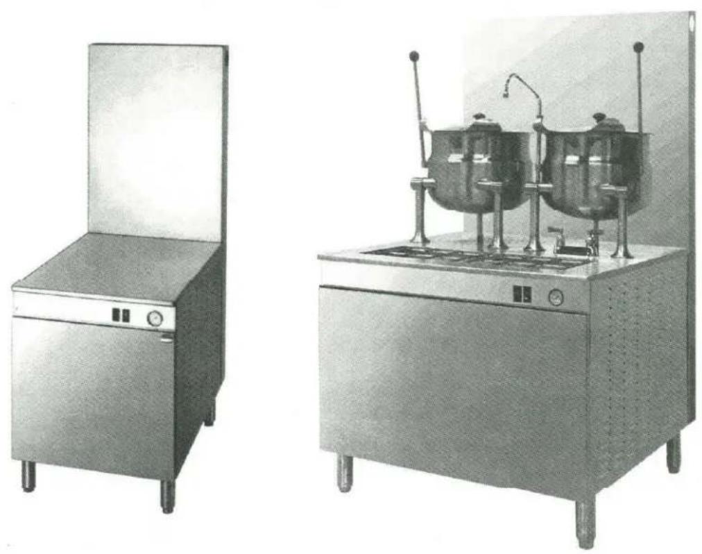
MODEL: 36/42GMK11/1/K6200/300
Cleveland Range, LLC
1333 East 179th Street
Cleveland, OH 44110
Phone: 216-481-4900
Fax: 216-481-3782
www.clevelandrange.com
260MBG 1/01
2/04
Cleveland STATEMENT OF POLICIES
LIMITED WARRANTY
CLEVELAND RANGE products are warranted to the original purchaser to be free from defects in materials and workmanship under normal use and service for the standard warranty period of one year from date of installation or 18 months from date of shipment, which ever comes first.
CLEVELAND RANGE agrees to repair or replace, at its option, f.o.b. factory, any part which proves to be defective due to defects in material or workmanship during the warranty period, providing the equipment has been unaltered, and has been PROPERLY INSTALLED, MAINTAINED, AND OPERATED IN ACCORDANCE WITH THE CLEVELAND RANGE OWNER'S MANUAL.
CLEVELAND RANGE agrees to pay any FACTORY AUTHORIZED EQUIPMENT SERVICE AGENCY (within the continental United States, and Hawaii) for reasonable labor required to repair or replace, at our option, f.o.b. factory, any part which proves to be defective due to defects in material or workmanship, during the labor warranty period. This warranty includes travel time not to exceed two hours and mileage not to exceed 50 miles (100 miles round-trip), BUT DOES NOT INCLUDE POST START-UP, TIGHTENING LOOSE FITTINGS, MINOR ADJUSTMENTS, MAINTENANCE, CLEANING OR DESCALING.
The standard labor warranty allows factory payment of reasonable labor required to repair or replace such defective parts. Cleveland Range will not reimburse the expense of labor required for the repair or replacement of parts after the standard warranty period, unless an Extended Labor Warranty Contract has been purchased to cover the equipment for the balance of the warranty period from the date of equipment installation, start-up, or demonstration.
PROPER INSTALLATION IS THE RESPONSIBILITY OF THE DEALER, THE OWNER-USER, OR INSTALLING CONTRACTOR, AND IS NOT COVERED BY THIS WARRANTY. Many local codes exist, and it is the responsibility of the owner and installer to comply with these codes. Cleveland Range equipment is built to comply with applicable standards for manufacturers, including UL, ANSI, NSF, ASME/Ntl. Bd., CSA, and others.
BOILER (Steam Generator) MAINTENANCE IS THE RESPONSIBILITY OF THE OWNER-USER AND IS NOT COVERED BY THIS WARRANTY. The use of good quality feed water is the responsibility of the Owner-User (see Water Quality Recommendations below). THE USE OF POOR QUALITY FEED WATER WILL VOID EQUIPMENT WARRANTIES. Boiler maintenance supplies, including boiler hand hole gaskets, are not warranted beyond the first 90 days after the date the equipment is placed into service. Preventive maintenance records must be available showing descaling per applicable Cleveland Operator Manual for Boiler Proration Program considerations.
WATER QUALITY RECOMMENDATIONS
| TOTAL DISSOLVED SOLIDS | less than | 60 parts per million |
| TOTAL ALKALINITY | less than | 20 parts per million |
| SILICA | less than | 13 parts per million |
| CHLORIDE | less than | 30 parts per million |
| pH FACTOR | greater than 7.5 | |
The foregoing shall constitute the sole and exclusive remedy of original purchaser and the full liability of Cleveland Range for any breach of warranty. THE FOREGOING IS EXCLUSIVE AND IN LIEU OF ALL OTHER WARRANTIES, WHETHER WRITTEN, ORAL, OR IMPLIED, INCLUDING ANY WARRANTY OF PERFORMANCE, MERCHANTABILITY, OR FITNESS FOR PURPOSE, AND SUPERSEDES AND EXCLUDES ANY ORAL WARRANTIES OR REPRESENTATIONS, OR WRITTEN WARRANTIES OR REPRESENTATIONS, NOT EXPRESSLY DESIGNATED IN WRITING AS A "WARRANTY" OR "GUARANTEE" OF CLEVELAND RANGE MADE OR IMPLIED IN ANY MANUAL, LITERATURE, ADVERTISING BROCHURE OR OTHER MATERIALS.
CLEVELAND RANGE'S liability on any claim of any kind, including negligence, with respect to the goods or services covered hereunder, shall in no case exceed the price of the goods or services, or part thereof, which gives rise to the claim. IN NO EVENT SHALL CLEVELAND RANGE BE LIABLE FOR SPECIAL, INCIDENTAL, OR CONSEQUENTIAL DAMAGES, OR ANY DAMAGES IN THE NATURE OF PENALTIES.
LIMITED EXTENDED WARRANTY COVERAGE
The purchase of a Limited Extended Warranty Contract extends the standard warranty coverage to the purchased period of time (one to two years) from the date of installation, start-up, or demonstration, whichever is sooner.
*An additional two years Parts and Labor Warranty can be purchased with each piece of Cleveland equipment for an additional 2% of the List Price per year. The 2% of list price charge will be the net invoice amount for each year of extended warranty purchased.
- Extended warranty must be purchased at the same time the equipment is purchased.
- Extended Warranty has the same exclusions as stated in our standard warranty.
Second year limited extended warranty coverage on Cleveland Steamers when purchased with a water filter applies to water related components only.
INSTALLATION INSTRUCTIONS
for
STEAMERS, STEAMER/KETTLES, MODULAR BOILER BASES, and KETTLES ON BOILER BASES
natural_image
Black-and-white photo of a laboratory apparatus with a control panel and tubing (no visible text or symbols)CONVECTION STEAMER with KETTLE
natural_image
Simple line drawing of a rectangular box with wheels and a side panel, no text or symbols present.MODULAR BOILER BASE
natural_image
Historical illustration of a vintage mechanical device with two large fans and control panels (no visible text or symbols)KETTLES ON BOILER BASE
Cleveland Range, Inc.
UNITED STATES
1333 East 179th St.
Cleveland, Ohio 44110
Phone: (216) 481-4900 • Telex: 98-0546 • FAX: (216) 481-3782
CANADA
Garland Commercial Ranges • 1177 Kamato Rd.
Mississauga, Ontario CN-L4W 1X4
Phone: (416) 624-0260 • FAX: (416) 624-0623
INSTALLATION INSTRUCTIONS FOR STEAMERS, STEAMER/KETTLES, MODULAR BOILER BASES, and KETTLES ON BOILER BASES
FOR YOUR SAFETY
Do not store or use gasoline or other flammable vapors and liquids in the vicinity of this or any other appliance.
WARNING
Installation of this equipment must be accomplished by qualified installation personnel, working to all applicable local and national codes. Improper installation of this product could cause injury or damage.
Cleveland Range equipment is designed and built to comply with applicable standards for manufacturers. Included among those certification agencies which have approved the safety of the equipment design and construction are: UL, A.G.A., NSF, ASME, CSA, CGA, and others.
Cleveland Range equipment is designed and certified for safe operation only when permanently installed in accordance with local and/or national codes. Many local codes exist, and it is the responsibility of the owner and installer to comply with these codes.
In no event shall Cleveland Range assume any liability for consequential damage or injury resulting from installations which are not in strict compliance with our installation instructions. Specifically, Cleveland Range will not assume any liability for damage or injury resulting from improper installation of equipment, including, but not limited to, temporary or mobile installations.
INSTALLATION INSTRUCTIONS FOR ALL MODELS
- These instructions must be retained by the owner/user for future reference. Gas-fired boilers are only to be installed in noncombustible areas that have provisions for adequate air supply. The term "boiler" will be used synonymously with "steam generator."
WARNING
The flooring that will be directly under the boiler, must also be made of a noncombustible material.
- Position: For proper operation and drainage, the equipment must be level. It should be placed next to an open floor drain. DO NOT POSITION THE UNIT DIRECTLY ABOVE THE FLOOR DRAIN. Observe all clearance requirements to provide air supply for proper operation, as well as sufficient clearance for servicing. The surrounding area must be free and clear of combustibles. Dimensions and clearance specifications are shown on the specification sheet.
- Install in accordance with local codes and/or the National Electric Code ANSI/NFPA No. 70-1987. Installation in Canada must be in accordance with the Canadian Electrical Code CSA Standard C22.1. Equipment that is connected to electricity must be grounded by the installer. A wiring diagram is provided inside the base cabinet.
- The drain line outlet discharges exhaust steam and hot condensate. Connect 1½" IPS piping (or larger) to extend the drain line to a nearby open floor drain. Up to two elbows and six feet of 1½" IPS (or larger) extension pipe should be connected to the drain termination. Drain piping extended six to twelve feet, or using three elbows, should be increased to 2" IPS. No more than two pieces of Cleveland Range equipment should be connected to one common drain line. The maximum length of extension from the drain termination should not exceed six feet and use no more than two elbows. The extension piping must have a gravity flow and vent freely to the air. This drain outlet must be free-vented to avoid the creation of back pressure in the steamer cooking compartments. To ensure a vented drain line, DO NOT, UNDER ANY CIRCUMSTANCES, CONNECT THE DRAIN OUTLET DIRECTLY TO THE FLOOR DRAIN OR SEWER LINE. Do not run the drain line discharge into PVC drain piping or any other drain piping material not capable of sustaining 180°F operation.
FAILURE TO OBSERVE THESE REQUIREMENTS CAN RESULT IN DAMAGE TO EQUIPMENT AND/OR THE POSSIBILITY OF INJURY.
(Continued on next page)
- Direct-steam connected pressure steamers do not require a cold water connection, and therefore steps #5 and #6 do not apply. Refer directly to step #7. A kettle fill faucet, if so equipped, requires a hot and/or cold water connection. The data contained in step #5 for cold water also applies to hot water.
- Connect COLD water supply plumbing to the line strainer. (Never connect hot water to the boiler's water fill line strainer). Constant flow pressure must be maintained between 35 and 60 psi, and not experience a pressure drop below 35 psi when other appliances are used. If the water pressure exceeds 60 psi, a pressure reducing valve must be installed in the water supply plumbing to reduce the water pressure to less than 60 psi. Locations and pressure data are shown on the specification sheet. 14 " IPS plumbing is sufficient for water supply lines up to 20 feet in length, but water supply lines longer than 20 feet should be at least 38 " IPS. Flush water supply lines thoroughly before connecting them to the unit. Use water which is low in total dissolved solids content and low in gas content to prevent internal scaling, pitting and corrosion of the steam generator, and carry-over of minerals into the steam. Water which is fit to drink can still contain highly detrimental impurities.
NOTE: If equipped with a kettle and kettle water fill swing spout, 38 " (10mm) hot and/or cold water connection(s) will be required at the swing spout's valve.
-
Turn on the cold water supply to the unit. Ensure that the manual water valve, inside the base cabinet, is open.
-
Connect the primary fuel supply in accordance with the following instructions. Location and other data are shown on the specification sheet.
For Gas-Fired Steam Generators:
Post, in a prominent location, instructions to be followed in the event the user smells gas. This information shall be obtained by consulting the local gas supplier. Install a sediment trap (drip leg) in the gas supply line, then connect gas supply piping to the boiler's gas valve piping. GAS-FIRED EQUIPMENT IS DESIGNED FOR INSTALLATION ONLY IN NON-COMBUSTIBLE LOCATIONS. THIS INCLUDES THE FLOORING THAT WILL BE DIRECTLY UNDER THE EQUIPMENT. Location, plumbing size, and pressure data are shown on the specification sheet. Boilers rated at less than 225,000 BTU require 3/4'' IPS gas supply piping, and boilers rated at 225,000 BTU or more require 1'' IPS gas supply piping. Natural gas supply pressure must be between 4'' - 14'' water column, and L.P. gas supply pressure must be between 12'' - 14'' water column. NEVER EXCEED 14'' WATER COLUMN ( 1/2 psi) GAS PRESSURE. If the gas supply pressure exceeds 14'' water column, a pressure regulating valve must be installed in the gas supply plumbing to reduce the gas pressure to less than 14'' water column. Installation must be in accordance with local codes, or in the absence of local codes, with the National Fuel Gas Code, ANSI Z223.1-1984. Installation in Canada must be in accordance with Installation Codes for Gas Burning Appliances and Equipment B149.1 and B149.2. Use a gas pipe joint compound which is resistant to LP gas. Turn the gas valve's control knob to "on" (the word "on" on the knob will be opposite the index on the valve's body). Test all pipe joints for leaks with soap and water solution. Never obstruct the flow of combustion and ventilation air. Observe all clearance requirements to provide adequate air openings into the combustion chamber. The appliance and its individual shut-off valve must be disconnected from the gas supply piping system during any pressure testing of that system at test pressures in excess of 1/2 psi ( 14'' water column or 3.45 kPa). The appliance must be isolated from the gas supply piping system at test pressures equal to or less than 1/2 psi ( 14'' water column or 3.45 kPa). A permanent 115 volt electrical connection is required at the junction box. The junction box location is shown on the specification sheet. The unit must be electrically grounded by the installer.
For Electric-Powered Steam Generators:
Connect electric power: location and data are shown on the specification sheet. Provide connection as required by your unit; either directly to the single contactor, or to the terminal block (when equipped with multiple contactors). Electric supply must match power requirements specified on the data plate inside the base cabinet. The copper wiring must be adequate to carry the required current at the rated voltage. A separate fused disconnect switch must be supplied and installed. The unit must be electrically grounded by the installer.
For Steam Coil Steam Generators:
Connect steam supply piping to the input side of the steam coil. Location and pressure data are shown on the specification sheet. Incoming steam pressure must be regulated between 35 and 45 psi. A 34'' strainer, equipped with a 20 mesh stainless steel screen, must be supplied and installed at the incoming steam connection point. Flush the steam line thoroughly before connecting it to the boiler. To ensure an adequate volume of steam, the branch steam supply line must be 34'' IPS minimum. Connect the inverted bucket trap to the outlet end of the steam coil. Fill the trap with water before installing it. A permanent 115 volt electrical connection is required at the junction box. The junction box location is shown on the specification sheet. The unit must be electrically grounded by the installer.
For Direct-Steam-Connected Steamers/Kettles:
Connect steam supply piping to the input side of the line strainer. Location and pressure data are shown on the specification sheet. Flush the steam line thoroughly before connecting it to the steamer. To ensure an adequate volume of steam, the branch steam supply line must be 34'' IPS minimum. (Direct-steam-connected kettles require 12'' IPS pipe if the kettle's total capacity is 20 gallons or less, and 34'' IPS pipe if the total capacity exceeds 20 gallons.) A permanent 115 volt electrical connection is required at the junction box. The junction box location is shown on the specification sheet. The unit must be electrically grounded by the installer. (Note: pressure steamers equipped with strictly manual steam and drain valves do not require an electrical connection.)
(Continued on reverse side)
(Continued)
- Press the top of the power on-off rocker switch. The red indicator light in the switch will come on and the boiler will begin to fill with water.
- Direct-steam-connected steamers are not equipped with self-generating boilers or "steam" switches. Therefore, these models do not require the 5-minute boiler water fill time, nor is it necessary to push a "steam" switch to produce steam, as indicated in step #9. As soon as the pressure gauge on the control panel registers 10 psi (5 psi for pressure steamers), preheating may begin. If you are operating a direct-steam-connected steamer, steps #9 and #10 do not apply. Refer directly to step #11.
- After about five minutes, the amber light in the "steam" switch will glow, indicating the water has reached a safe operating level in the boiler. The "steam" switch can now be pressed (momentarily) in order to produce steam in the boiler. This will activate the energy source (electric heaters, gas burners, or steam solenoid valve), and the amber light will go out. The energy source cannot be activated until the boiler contains sufficient water, indicated by the amber light. The "steam" switch must be pushed to re-start the steamer after it is shut off for any reason (including a momentary power interruption). Do not attempt to start or operate this appliance during a power failure. Whenever the amber light is illuminated, the heater, steam supply, or burners are off, and no steam is being generated. (Note: for units containing gas-fired boilers only: if the burners fail to ignite in four seconds, a safety circuit will de-energize the system.: In this event, momentarily press the power switch to the "off" position, then back to the "on" position. The "steam" switch amber light should be on. Wait 5 minutes, then press the "steam" switch to start the burner ignition cycle once again.)
- Check to ensure that the water in the boiler's sight gauge glass automatically stays about 13 full when the boiler is started up and operated.
- Check to ensure that the steam pressure gauge registers 10 psi (5 psi for pressure steamers).
The steam pressure is factory-adjusted to provide the proper pressure. In some cases, however, the factory setting may shift due to shaking in transit, and resetting will be required after installation. Proper adjustments and maintenance procedures are detailed on a separate data sheet entitled "Steam Pressure Adjustments." Adjustments should be made only by qualified service personnel. The factory pressure settings shown in the accompanying chart should never be exceeded. - When the installation is complete and free of leaks, refer to the Operating Procedures page, in order to check for proper operation of the unit.
| GAUGE PRESSURE READING WITH NO STEAM FLOW (STATIC PRESSURE) | ||||||||
| Self-Contained Steam Generator Gas or Electric | Self-Contained Steam Coil Generator | Direct-Connect (To "House" Steam Supply) | ||||||
| Steamer's Pressure Reducing Valve | Operating Pressure Switch | High Limit Safety Pressure Switch | Operating Pressure Switch | High Limit Safety Pressure Switch | Steam Supply Pressure Range | Steamer's Pressure Reducing Valve | Steam Supply Pressure Range | |
| Equipment | ||||||||
| Steam Generator Only 5 psi | N/A | 5 psi | 10 psi | 5 psi | 10 psi | 30-45 psi | N/A | N/A |
| Pressure Steamer | N/A | 5 psi | 10 psi | 5 psi | 10 psi | 30-45 psi | 5 psi | 12-45 psi |
| Pressure Steamer With Any Kettle(s) | 5 psi | 10 psi | 15 psi | 5 psi | 10 psi | *30-45 psi | 5 psi | 12-45 psi |
| Steam Generator Only 10 psi | N/A | 10 psi | 15 psi | 10 psi | 15 psi | 30-45 psi | N/A | N/A |
| Kettle Only — All | N/A | 10 psi | 15 psi | N/A | N/A | N/A | N/A | 5-45 psi |
| Convection Steamer With or Without Kettles | N/A | 10 psi | 15 psi | 10 psi | 15 psi | *35-45 psi | 10 psi | 15-45 psi |
"Kettles are to be connected to the "house" steam supply.
CLEVELAND
INSTALLATION, OPERATION AND REPAIR MANUAL
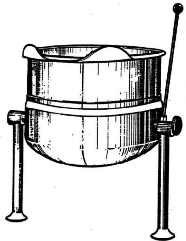
TABLE - TOP DIRECT STEAM KETTLE
MODEL# KDT-T
natural_image
Line drawing of a metal cauldron with two legs and a handle, no text or symbols presentSE95008 - 1
CLEVELAND RANGE INC.
1333 East 179th St.
Cleveland, Ohio
U.S.A. 44110
(216)481-4900
INSTALLATION INSTRUCTIONS FOR DIRECT STEAM KETTLES
WARNING: Installation of kettle must be accomplished by qualified installation personnel, working to all applicable local and national codes. Improper installation of product could cause injury or damage.
This equipment is built to comply with applicable standards for manufacturers. Included among those approval agencies are: UL, NSF, ASME/NtL.Bd., CSA, ETL, and others. Many local codes exist, and it is the responsibility of the owner and installer to comply with these codes.
INSPECTION
Before unpacking visually inspect the unit for evidence of damage during shipping. If damage is noticed, do not unpack the unit, follow shipping damage instructions.
SHIPPING DAMAGE INSTRUCTIONS
If shipping damage to the unit is discovered or suspected, observe the following guidelines in preparing a shipping damage claim.
- Write down a description of the damage or the reason for suspecting damage as soon as it is discovered. This will help in filling out the claim forms later.
-
As soon as damage is discovered or suspected, notify the carrier that delivered the shipment.
-
Arrange for the carrier's representative to examine the damage.
- Fill out all carrier claims forms and have the examining carrier sign and date each form.
INSTALLATION
The first installation step is to refer to the specification sheet for clearance requirements, in order to determine the location of the kettle. Next, carefully cut open the shipping carton for easy removal of the kettle.
ASSEMBLY
KDT-T SERIES (Table-Top Models)
Table-top models must be positioned on a firm stand or existing counter top, and secured in place. An optional modular cabinet base, with level-adjustable legs, is available. Make two 3/4" holes, for the kettle legs, in a cabinet or countertop. Remove the leg mounting locknuts from the kettle's legs and install the legs into the two 3/4" holes. Secure the kettle to its base by refastening the locknuts from underneath the cabinet or countertop. Place a carpenter's level on the kettle rim and level the cabinet. Once the kettle is secure, screw the tilt handle into the mounting block welded to the side of the kettle.
INSTALLATION
OF SERVICE CONNECTIONS
Install service connections as required. Locations and other data are shown on the specification sheet.
STEAM
All steam plumbing to and from the kettle and steam boiler should be thoroughly cleaned and inspected for dirt and debris before final connections to the kettle are made.
Refer to the specification sheet for the minimum allowable size of the branch steam supply plumbing (from the steam "main" plumbing or a nearby boiler). Generally, kettles require 1/2" i.p.s. pipe. Kettles require 5-50 psi steam pressure. If the steam supply pressure exceeds 50 psi, a pressure reducing valve is required. The steam inlet is at the right side of the kettle, as seen from the front.
(Note: Table-top kettles are available, through special order ONLY, with the steam supply valve on the left side of the kettle. In this rare instance, the steam inlet would be on the left side of the kettle, as seen from the front. The steam condensate trap would then be on the right side.)
CONDENSATE
The steam condensate trap must be plumbed to a drain, using minimum 1/2" NPT plumbing. The condensate line is limited to a maximum rise of 10 feet in order for the steam pressure to adequately force the condensate through the plumbing. Any higher rise requires a pump.
If the steam boiler to which this kettle is installed has a condensate return, a 1/2" (13mm) steam strainer, a 1/2" (13mm) steam trap, and a 1/2" (13mm) check valve must be installed on the output (condensate) side of the kettle.
WATER
The water faucet, with swing spout, requires 1/2 inch O.D. copper tube plumbing for hot/or cold water supplies to the faucet (if so equipped).
FINAL INSTALLATION CHECK
- Partially fill the kettle with water.
- Slowly turn the steam supply valve's knob to the open position.
- Release the safety valve, ensuring that the steam escapes freely. Stay clear of steam exhaust when releasing the safety valve.
- Observe that the water in the kettle comes to a boil.
- Close the steam supply valve.
- Drain off the water by tilting the kettle.
OPERATION
Ensure that there is an adequate steam supply to the kettle.
Turn the steam control valve to the full open position by turning the knob counterclockwise, then allow the kettle to preheat.
NOTE: When cooking egg and milk products, the kettle should NOT be preheated, as products of this nature adhere to hot cooking surfaces. These types of foods should be placed in the kettle before heating is begun.
Fill kettle with product to desired level.
When the product has reached the desired temperature, regulate the heat, as required, by turning the steam control valve for less steam, and therefore, a lower temperature.
When cooking is complete, close the steam control valve by turning the knob.
For kettle/steamer combinations: If the boiler in a steamer is supplying steam to a kettle, always heat the kettle first. After the kettle contents are heated, and the boiler's steam pressure returns to normal, the steamer may be used. Pressure steamer compartments should be sequentially started, and preheated before cooking.
NOTE: As with cleaning food soil from any cookware, an important part of kettle cleaning is to prevent foods from drying on. For this reason, cleaning should be completed immediately after cooked foods are removed. Please refer to the "Care and Cleaning" instructions for detailed kettle washing procedures.
CARE AND CLEANING
Your kettle must be cleaned regularly to maintain its fast, efficient cooking performance, and to ensure its continued safe, reliable operation.
WARNING: Do not use chlorine base detergent.
- Prepare a warm water and mild detergent solution in the kettle.
- Remove food soil inside the kettle using a nylon brush. Do not use a metal bristle brush, as this may permanently damage the kettle's stainless steel surface.
- Loosen food which is stuck to the kettle by allowing it to soak at a low temperature (simmer or low boil).
- Tilt kettle forward to drain the wash water.
- Rinse the kettle interior thoroughly, then drain rinse water.
- Leave the cover and draw-off valve open when the kettle is not in use.
- Using mild soapy water and a damp sponge, wash the exterior of the kettle, rinse, and dry.
NOTE: For more difficult cleaning applications, one of the following can be used: alcohol, baking soda, vinegar, or a solution of ammonia in water. Avoid the use of chloride cleansers, which may damage the kettle's stainless steel surface.
WARNING: Steel wool should never be used for cleaning the cooking chamber of the kettle. Particles of steel wool become embedded in the cooking surface and rust, and may corrode the stainless steel.
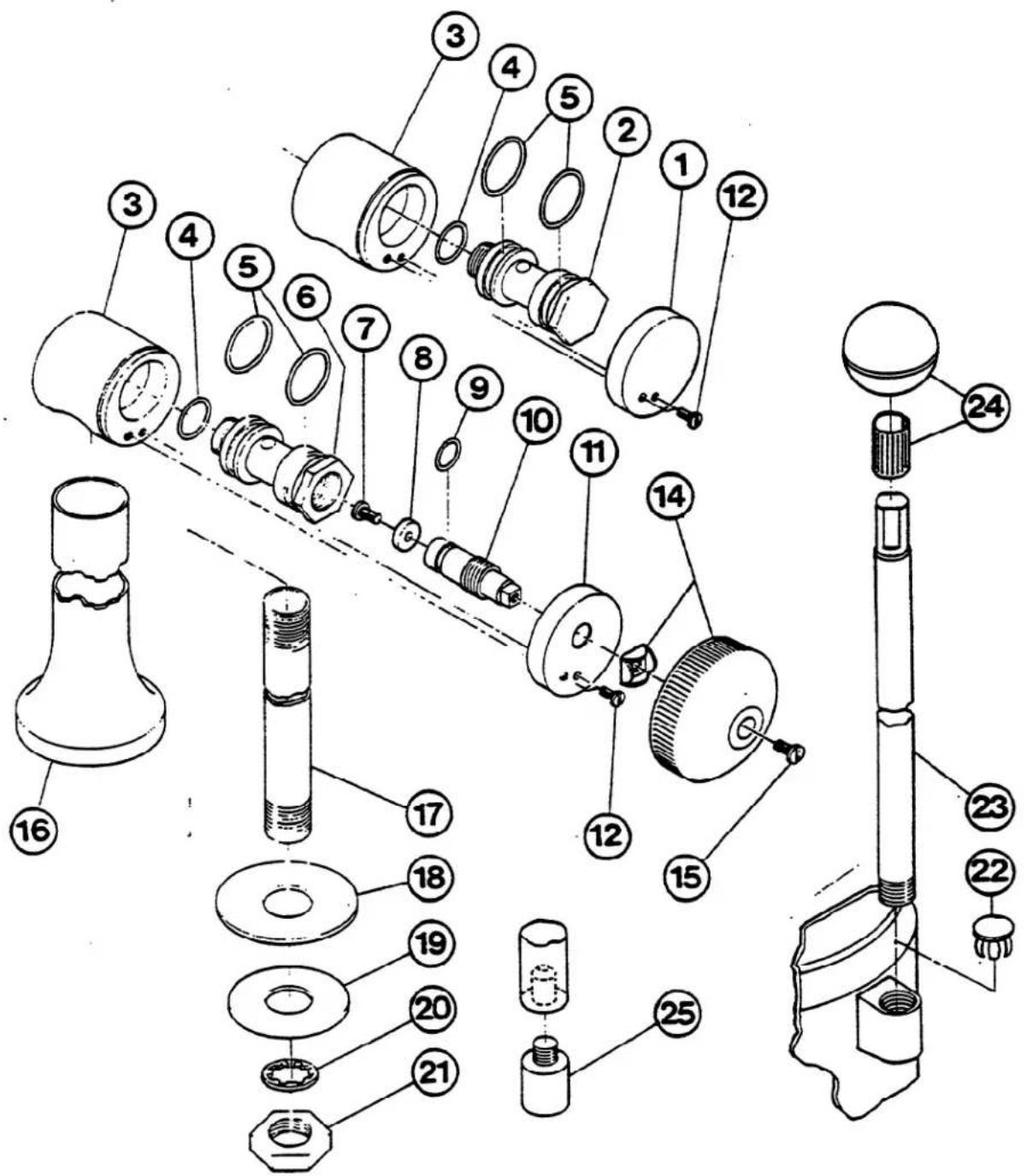
STEAM CONTROL
-
FA11089 Screw, 8-32 x 1/4" 1
-
KE51713 Washer, operating stem 1
-
FA00110 "O" Ring 1
-
KE50459 Operating stem, stainless steel 1
-
KE50457 End cap, steam inlet 1
-
FA11054 Screw, 6-32 x 3/8" 2
-
SE00028 Steam inlet knob assy. 1
-
FA11092 Screw, 8-32 x 1/2" 1
-
KE00200 Leg weldment (1 gal. model) 2
KE00197 Leg weldment (6 gal. model) 2
KE00198 Leg weldment (12 gal. model) 2
KE00199 Leg weldment (20 gal. model) 2
- KE50465 Service pipe (1 gal. model) 2
KE52030 Service pipe (6 gal. model) 2
KE50463 Service pipe (12 gal. model) 2
KE50464 Service pipe (20 gal. model) 2
-
KE50467 Washer, foot 2
-
FA30502 Washer, satin coat 2
-
KE51898 Washer, lock 2
-
FI00222 Lock nut, 1/2 NPS 2
-
KE50475 Plug button 1
-
KE50886 Handle (1 gal. model) 1
SK50051 Handle (6,12 gal. model) 1
KE50803 Handle (20 gal. model) 1
-
KE50151 Knob 1
-
KE50474 Foot 1
OPERATING CONTROLS
For your better understanding and confidence, the following explanation of the control system on this kettle is offered.
ITEM NO. DESCRIPTION
FUNCTION
14
Steam Inlet Knob
Turns the steam on or off to the kettle.
23-24
Tilting Handle
Used for tilting the kettle.
SERVICING GUIDE
This section contains information intended for use by Authorized Service Personnel only.
A/ PROBLEM: Kettle heats too slowly or does not come to a boil.
| Probable Cause | Remedy | |
| 1. | Inadequate steam flow. | Check for correct steam using chart below.If kettle is connected to a steamer and powered by a generator the units should be operated sequentially (kettle boiling first, then start steamer). |
| 2. | Steam trap not operating properly. | The trap should open periodically to dump condensate, then close. If it does not open or close it should be cleaned or replaced. |
| 3. | Food batches are not always the same. | When checking make certain that the original state (ie. fresh or frozen) and quantity of food product is the same. |
B/ PROBLEM: The trunnion housing leaks steam.
| Probable Cause | Remedy | |
| 1. | Trunnion "O" rings are worn. | Replace "O" rings. |
STEAM FLOW RATING OF STEAM GENERATORS
| GAS INPUTBTU/HOUR | STEAM OUTPUTLBS./HOUR | BOILERH.P. |
| 100,000 | 60 | 1.7 |
| 160,000 | 95 | 2.8 |
| 200,000 | 125 | 3.6 |
| 250,000 | 150 | 4.4 |
| 300,000 | 180 | 5.2 |
| ELECTRICKW INPUT | ||
| 18 KW | 60 | 1.7 |
| 24 KW | 70 | 2.0 |
| 27 KW | 90 | 2.6 |
| 36 KW | 120 | 3.5 |
| 48 KW | 150 | 4.3 |
STEAM FLOW RATE REQUIREMENTS FOR KETTLES
| Capacity Gal./Lit. | Fast Cooking | Medium Speed Cooking | Stock Kettle |
| 5/17 | 11 | 9 | 6 |
| 10/42 | 22 | 18 | 11 |
| 25/95 | 55 | 44 | 28 |
| 40/151 | 88 | 70 | 44 |
| 60/227 | 132 | 105 | 66 |
| Note: Above shows lbs. per hour with 10-15 psig steam at the kettle. The use of higher steam pressures (20-25 psig) will reduce heat-up time 5 to 20%. | |||
STEAM GENERATOR (2 PROBE TYPE) MAINTENANCE PROCEDURES
CAUTION: Service on the generator must be performed only by a trained and experienced service technician, thoroughly familiar with servicing steam generators. No work should be done on the steam generator while it is pressurized or hot. Be sure all energy sources are shut off before the start of any work.
The steam generator must be drained under pressure (blowdown) after a maximum of 8 hours of use. If the generator's feedwater contains more than 300 parts per million of total dissolved solids, the generator must have a blowdown after each 4-6 hours of use. "Blowdown" means the generator must be drained under pressure.
THE GENERATOR "BLOWDOWN" IS PERFORMED BY SHUTTING OFF THE UNIT'S RED-LIGHTED "POWER" SWITCH WHILE THE GENERATOR IS AT NORMAL OPERATING PRESSURE. WHEN THE BOTTOM OF THE "POWER" ROCKER SWITCH IS PUSHED, ITS RED LIGHT GOES OUT, AND THE DRAIN VALVE AUTOMATICALLY OPENS, DRAINING THE GENERATOR. AN AUTOMATICALLY-TIMED SOLENOID VALVE WILL FLUSH THE DRAIN FOR 3 MINUTES, THEN SHUT OFF. AFTER 3 MINUTES, THE UNIT CAN BE RESTARTED.
Even though the "Blowdown" is performed faithfully each day, it will still be necessary to have a qualified service technician periodically inspect the inside of the generator for scaling or pitting. The generator's hand hole plate should be removed at regular intervals, so that it and the inside of the generator can be inspected. The hand hole plate should be cleaned and examined each time it is removed. If the hand hole plate is chipped or cracked, or over three years old, install a new one. A new hand hole gasket should always be installed.
Scaling indicates a high concentration of dissolved minerals in the feed water. Pitting indicates an excess acid condition. The best way to reduce servicing time and to assure a long generator life is to provide feed water that is low in mineral content and low in gas content. Water that is fit to drink can still be high in impurities that are highly detrimental to a steam generator. Consult the state department of water for an on-the-premises water analysis and for recommendations concerning steam generator feed water treatment (if required), in order to remove or reduce harmful concentrations of minerals.
CAUTION: Neven tighten the hand hole plate nut when the steam generator is in use, hot, or otherwise pressurized. Never tighten nut over 15 foot-pounds torque. Overtightening may cause uneven stress, which may result in the weakening and possible breakage of the plate.
The "Blowdown" procedure will not completely remove the mineral deposits that adhere to the top of the generator.
It will be necessary to periodically have scale accumulations removed from the inside of the steam generator by a qualified service technician. Only a U.S.D.A. approved acid cleaner should be used to descale the generator.
Descaling should be done once a year, but in poor water (highly mineralized) areas it may be needed two or three times a year.
Failure to periodically remove scale from the inside of the generator will result in greatly reduced generator life.
Check the safety valve once a month while the steam generator is pressurized. Test by pulling the safety valve lever. The valve must open freely and snap closed when released. If it does not, or if it drips constantly, a new safety valve is needed.
If the steam generator is to be left idle for three months or more, it should be drained and dried out and the hand hole plate left off.
CLEVELAND RANGE, INC., 1333 EAST 179th ST., CLEVELAND, OHIO 44110
0485
LITHO IN U.S.A.
Manufacturer reserves right of design improvement or modification, as warranted.
WATER QUALITY REQUIREMENTS — 2-PROBE TYPE STEAM GENERATOR PROTECTION AND MAINTENANCE
A steam generator, or boiler, unlike other types of water-using kitchen equipment, distills the water in order to make steam. Nearly all feed-water sources contain dissolved minerals in varying degrees of concentration. As this water is boiled, pure steam rises from its surface, upward to the cooking compartment(s), leaving minerals behind, that can become harmful to the steam generator. If minerals are allowed to accumulate inside the steam generator, they will solidify as a scale. Then, malfunctioning will occur, and serious equipment damage may result.
The use of good quality generator feed water is the responsibility of the owner/user. The use of poor quality feed water could void equipment warranties. The minimum treatment required in most areas is water softening, although local water conditions may require more intensive pretreatment than simply a water softener.
Scale problems occur when feed water is high in hardness, total dissolved solids, silica, and alkalinity. Water softening will only reduce the water's hardness, which is the presence of dissolved salts of magnesium and calcium. Water softening will not affect the multitude of other minerals found in most water supplies. Because generator scale is the result of the precipitation of many minerals, the best property to control, for generator feed water, is total dissolved solids, not just hardness.
The recommended minimum water quality standards, whether untreated or pre-treated, based upon 8 hours of use per day, and a Daily Blowdown, are as follows:
| TOTAL DISSOLVED SOLIDS |
| TOTAL ALKALINITY |
| SILICA |
| pH FACTOR |
| less than |
| less than |
| less than |
| greater than |
| 60 parts per million |
| 27 parts per million |
| 13 parts per million |
| 7.5 |
Consult the state department of water or a local water treatment specialist for an on-the-premises water analysis and for recommendations concerning steam generator feed water treatment (if required), in order to remove or reduce harmful concentrations of minerals.
If the recommended water quality requirements are met without supplemental treatment, or if treatment is applied, resulting in feed water quality meeting the prescribed standards, the steam generator will need to be blown down only once every 8 hours. In addition, the inside of the generator requires an inspection (for excessive lime accumulation) only once every six months. Chemically descale the generator as required.
If a pre-treatment unit cannot be installed, and the recommended water quality requirements are not met, the following procedures should be followed, in order to achieve maximum steam generator service life. The steam generator should be blown down after each 4-6 hours of use. Have the steam generator inspected, inside and outside, by a qualified technician every three months. If the inside of the generator is heavily coated with scale, have it chemically descaled by a qualified service technician.
INSTRUCTIONS FOR CHEMICALLY DESCALING 2-PROBE TYPE STEAM GENERATORS
WARNING: Steam under pressure may cause serious injury and bodily harm when it is accidentally or carelessly released. Improper handling of acid could cause serious, permanent injury. Therefore, service of the steam generator should only be performed by trained and experienced personnel, thoroughly familiar with servicing generators.
There are a number of commercial descaling chemicals available, produced by various manufacturers. Those utilizing a sulfamic acid base, which can be identified by its powdered form, are safe and compatible with our food preparation equipment. It is imperative that the acid used for descaling be FDA approved, for use in food preparation equipment. Various manufacturers may include additional chemicals to increase potency, and therefore, instructions for a specific brand should be followed carefully. If instructions are not provided with the deliming chemical you purchase, the following general guidelines may be followed.
WARNING: Exercise care when handling acid. Avoid contact with skin, eyes, or clothing. Wear safety glasses or face shield, along with rubber gloves and rubber apron. In case of exposure to clothing, remove clothing and flush with water. In case of exposure to skin or eyes, flush with water for 15 minutes and get immediate medical attention. Do not take internally. Keep out of the reach of children.
Be sure the generator has been drained, de-pressurized, and is cool. Open the hand hole access plate on the front of the generator and place approximately 8-10 pounds of sulfamic acid inside the generator. Put a new hand hole gasket on the hand hole plate, and replace the hand hole plate, tightening the bar and nut assembly to a maximum of 15 foot pounds torque. The generator must be completely filled with water (fill the generator beyond its normal, automatic fill point of 2/3 up in the sight gauge). This can be accomplished by temporarily disconnecting the wire from the water level probe at the water level control board. The board is marked "HI" at this connection point. Turn the main on-off rocker switch to the "ON" position, then close the manual water feed valve when the generator is completely filled. Leave the on-off rocker switch in the "on" position to prevent the generator from automatically draining. Reconnect the probe wire to the "HI" terminal of the water level control board. Let the solution stand for several hours, then flush with water. Rinse with a solution of bicarbonate of soda to neutralize any acid residue, and again, flush with water. Be sure to reconnect the wire to the water level control board and to open the manual water feed valve.
CAUTION: Never tighten the hand hole plate nut when the steam generator is in use, hot, or otherwise pressurized. Never tighten nut over 15 footpounds torque. Overtightening may cause uneven stress, which may result in the weakening and possible breakage of the plate.
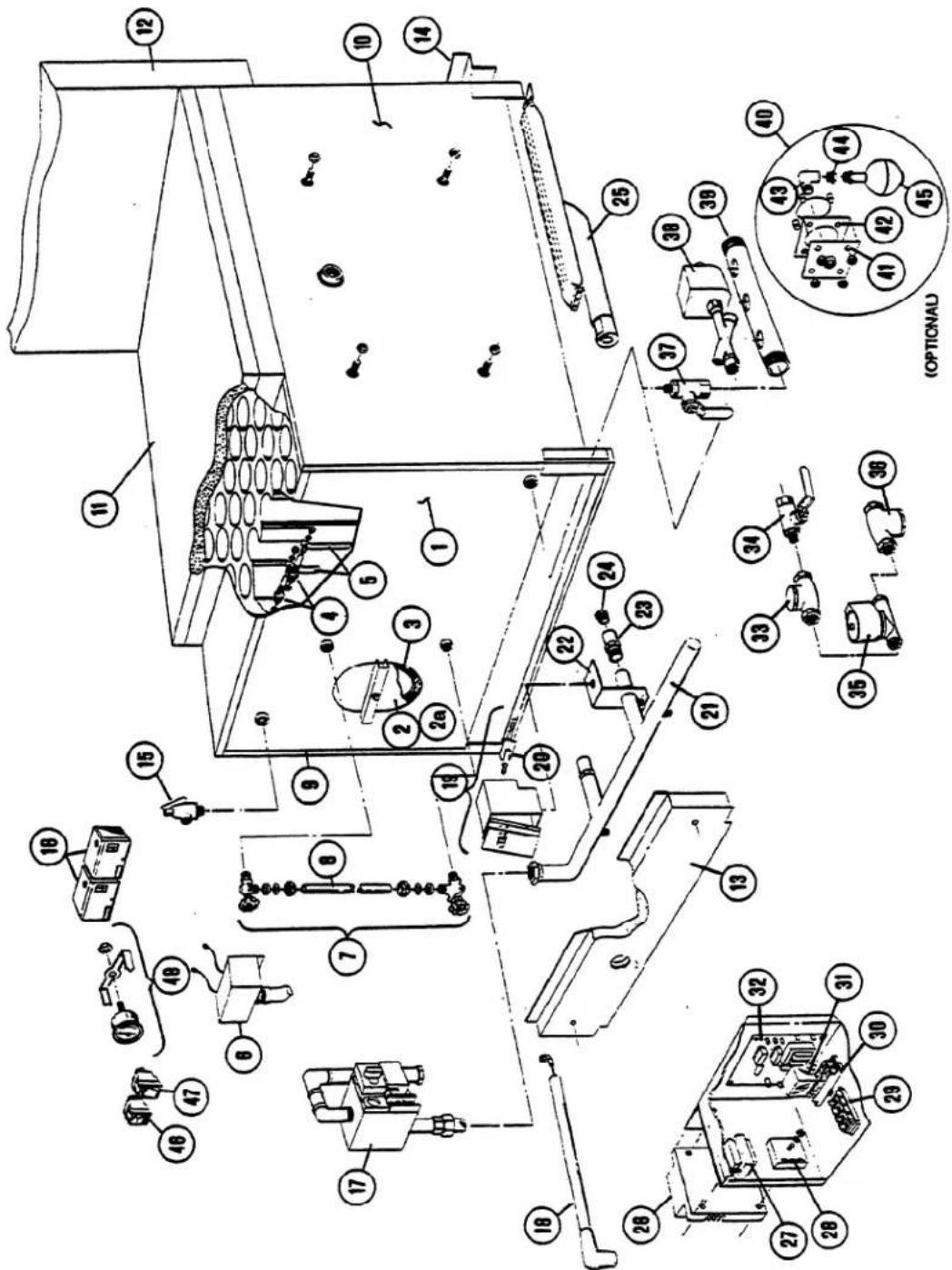
GAS STEAM GENERATOR (BOILER) ASSEMBLY - 2 PROBE TYPE
SMALL: 100,000 BTU (2 Burners) & 200,000 BTU (4 burners)
LARGE: 250,000 BTU (5 burners) & 300,000 BTU (6 burners)
CLEVELAND RANGE, INC., 1333 EAST 179th ST., CLEVELAND, OHIO 44110
Manufacturer reserves right of design improvement or modification, as warranted.
GAS STEAM GENERATOR (BOILER) ASSEMBLY - 2 PROBE TYPE SMALL: 100,000 BTU (2 Burners) & 200,000 BTU (4 burners) LARGE: 250,000 BTU (5 burners) & 300,000 BTU (6 burners)
| REFERENCE NUMBER | PART NUMBER | DESCRIPTION | REFERENCE NUMBER | PART NUMBER | DESCRIPTION |
| 1 | 43898 | Small boiler shell only (100,000/200,000 BTU), with legs, studs, hand hole plate assembly and top flue bracket. | 44156 | 5-burner rear burner support | |
| 44157 | 6-burner rear burner support | ||||
| 43899 | Large boiler shell only (250,000/300,000 BTU), with legs, studs, hand hole plate assembly, and top flue bracket. | 15 | 22130 | Safety valve, 8 psi | |
| 22131 | Safety valve, 15 psi | ||||
| 16 | 19947 | Pressure switch | |||
| 44173 | Small boiler shell (43898) above, also including insulation panels, top flue collector with insulation, sight gauge, two probes and extensions with cover box. | 17 | 22228 | Gas control valve, natural gas, small boiler (100,000/200,000 BTU) | |
| 22230 | Gas control valve, natural gas, large boiler (250/300,000 BTU) | ||||
| 44172 | Large boiler shell (43899) above, also including insulation panels, top flue collector with insulation, sight gauge, two probes and extensions with cover box. | 22231 | Gas control valve, L.P. gas, small and large boilers (100,000/200,000 and 250,000/300,000 BTU) | ||
| 2 | 40421 | Hand hole plate assembly including bar, nut, and gasket. | 18 | 44169 | Ignitor cable |
| 19 | 44096 | Ignitor box assembly with ignitor | |||
| 2a | 43748 | Hand hole plate only | 20 | 05101 | Ignitor electrode |
| 3 | 07106 | Hand hole gasket, 4" x 6" oval | 21 | 40918 | Gas manifold, 2-burner |
| 4 | 40462 | Probe | 40920 | Gas manifold, 4-burner | |
| 5 | 101466 | Probe extension set (set of two) | 40921 | Gas manifold, 5-burner | |
| 6 | 52305 | Probe cover box | 40922 | Gas manifold, 6-burner | |
| 7 | 40445 | Water gauge set with glass | 22 | 52602 | Manifold alignment bracket |
| 07108 | Fibre washer (2 required) | 23 | 19632 | Orifice holder | |
| 23132 | Gauge glass washer (2 required) | 24 | 15453 | Burner orifice, natural gas | |
| 8 | 07302 | Gauge glass only, 6" long | 15450 | Burner orifice, L.P. gas | |
| 9 | 44043 | Left side insulation panel assembly | 25 | 02497 | Burner |
| 440431 | Left side insulation panel assembly for L.P. gas - 100,000/200,000 BTU boiler only | 26 | 03546 | Spark ignition control module | |
| 27 | 20528 | 24 volt transformer | |||
| 10 | 44042 | Right side insulation panel assembly | 28 | 20478 | Internal timer, 3 minute |
| 440421 | Right side insulation panel assembly for L.P. gas - 100,000/200,000 BTU boiler only | 29 | 44164 | Terminal block, 4 pole | |
| 30 | 03525 | Relay socket | |||
| 11 | 42398 | Top flue collector with insulation, for small boiler (100,000/200,000 BTU) | 31 | 03524 | Relay |
| 42399 | Top flue collector with insulation, for large boiler (250,000/300,000 BTU) | 32 | 23198 | Control board, water level and IWCO | |
| 33 | 22102 | Check valve, 1⁄4" | |||
| 42360 | Internal flue riser assembly for small boiler (100,000/200,000 BTU) | 34 | 03276 | 1⁄4" Ball valve, water supply shut off | |
| 35 | 22223 | Solenoid valve, water feed | |||
| 42361 | Internal flue riser assembly for large boiler (250,000/300,000 BTU) | 36 | 19870 | Line strainer, 1⁄4" | |
| 37 | 03277 | 1⁄4" Ball valve, manual drain | |||
| 13 | 44134 | 2-burner front baffle assembly - natural gas | 38 | 22221 | Solenoid valve, boiler drain |
| 44135 | 4-burner front baffle assembly - natural gas | 39 | 13252 | Drain manifold | |
| 40840 | 5-burner front baffle assembly - natural gas | 40 | 45006 | Low water cut-off assembly (California only) | |
| 40842 | 6-burner front baffle assembly - natural gas | 41 | 41943 | LWCO mounting plate (California only) | |
| 44150 | Front burner baffle assembly for L.P. gas - 100,000/200,000 BTU boiler only (not shown) | 42 | 07128 | Gasket (California only) | |
| 44170 | Right side burner baffle assembly for L.P. gas - 100,000/200,000 BTU boiler only (not shown) | 43 | 05253 | Brass street elbow (California only) | |
| 44 | 02623 | 1⁄2" - 1⁄4" Brass reducing bushing (California only) | |||
| 44171 | Left side burner baffle assembly for L.P. gas - 100,000/200,000 BTU boiler only (not shown) | 45 | 19995 | Float switch, IWCO (California only) | |
| 14 | 44153 | 2-burner rear burner support | 46 | 19993 | DPDT Power switch |
| 44155 | 4-burner rear burner support | 47 | 19994 | SPST Momentary contact reset switch | |
| 48 | 07167 | Pressure gauge, 0-30 psi, 11⁄2" |
CLEVELAND RANGE, INC., 1333 EAST 179th ST., CLEVELAND, OHIO 44110
Manufacturer reserves right of design improvement or modification, as warranted.
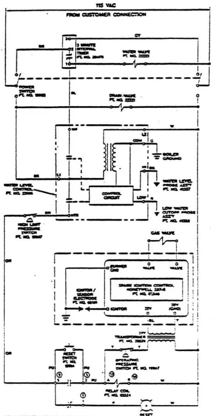
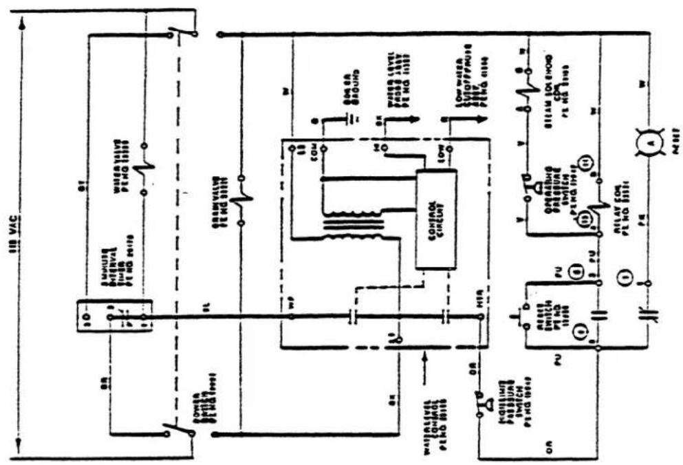
2-PROBE, SPARK IGNITION TYPE GAS BOILER-
SOLID STATE CONTROL WIRING
flowchart
graph TD
    A["Power Switch PC NO. 1988"] --> B["3 Minute Internal Timer PT NO. 2047"]
    B --> C["WATER VALVE PT NO. 2333"]
    C --> D["DRAM VALVE PT NO. 2333"]
    D --> E["CONTROL CIRCUIT"]
    E --> F["CON"]
    E --> G["LOW"]
    E --> H["COOL"]
    E --> I["BOLLER GROUND"]
    E --> J["SMR"]
    E --> K["SMR"]
    E --> L["SMR"]
    E --> M["SMR"]
    E --> N["LTR"]
    E --> O["SMR"]
    E --> P["SMR"]
    E --> Q["SMR"]
    E --> R["SMR"]
    E --> S["SMR"]
    E --> T["SMR"]
    E --> U["SMR"]
    E --> V["SMR"]
    E --> W["SMR"]
    E --> X["SMR"]
    E --> Y["SMR"]
    E --> Z["SMR"]
    E --> AA["SMR"]
    E --> AB["SMR"]
    E --> AC["SMR"]
    E --> AD["SMR"]
    E --> AE["SMR"]
    E --> AF["SMR"]
    E --> AG["SMR"]
    E --> AH["SMR"]
    E --> AI["SMR"]
    E --> AJ["SMR"]
    E --> AK["SMR"]
    E --> AL["SMR"]
    E --> AM["SMR"]
    E --> AN["SMR"]
    E --> AO["SMR"]
    E --> AP["SMR"]
    E --> AQ["SMR"]
    E --> AR["SMR"]
    E --> AS["SMR"]
    E --> AT["SMR"]
    E --> AU["SMR"]
    E --> AV["SMR"]
    E --> AW["SMR"]
    E --> AX["SMR"]
    E --> AY["SMR"]
    E --> AZ["SMR"]
    E --> BA["SMR"]
    E --> BB["SMR"]
    E --> BC["SMR"]
    E --> BD["SMR"]
    E --> BE["SMR"]
    E --> BF["SMR"]
    E --> BG["SMR"]
    E --> BH["SMR"]
    E --> BI["SMR"]
    E --> BJ["SMR"]
    E --> BK["SMR"]
    E --> BL["SMR"]
    E --> BM["SMR"]
    E --> BN["SMR"]
    E --> BO["SMR"]
    E --> BP["SMR"]
    E --> BQ["SMR"]
    E --> BR["SMR"]
    E --> BS["SMR"]
    E --> BT["SMR"]
    E --> BU["SMR"]
    E --> BV["SMR"]
    E --> BW["SMR"]
    E --> BX["SMR"]
    E --> BY["SMR"]
    E --> BZ["SMR"]
    E --> CA["SMR"]
    E --> CB["SMR"]
    E --> CC["SMR"]
    E --> CD["SMR"]
    E --> CE["SMR"]
    E --> CF["SMR"]
    E --> CG["SMR"]
    E --> CH["SMR"]
    E --> CI["SMR"]
    E --> CJ["SMR"]
    E --> CK["SMR"]
    E --> CL["SMR"]
    E --> CM["SMR"]
    E --> CN["SMR"]
    E --> CO["SMR"]
    E --> CP["SMR"]
    E --> CR["SMR"]
    E --> CS["SMR"]
    E --> CT["SMR"]
    E --> CU["SMR"]
    E --> CV["SMR"]
    E --> CW["SMR"]
    E --> CX["SMR"]
    E --> CY["SMR"]
    E --> CZ["SMR"]
RELAY SOCKET NOT SHOWN PT NO ISS
CIRCLED NUMBERS - CORRESPOND TO RELAY
SOCKET CONNECTIONS
CAS GENERATOR CONTROL WIRING
C-14005-8
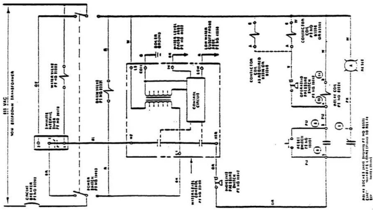
2-PROBE TYPE STEAM COIL BOILER-
SOLID STATE CONTROL WIRING
BELAT SOCKES (NOT SHOWN) PI NO 01135 EFFECTED NUMBERS CONMISSOUND TO BELAT SOCKIT CONNECTIONS
C10010
STEAM COIL GENERATOR CONTROL WINING
2-PROBE TYPE ELECTRIC BOILER-
SOLID STATE CONTROL WIRING
Descaling Procedure for Two-Probe Steam Generators
The steam generator should be descaled at least once a month, depending on scale buildup. If you have serious steam generator scale buildup, install a water treatment system for the steamer. Cleveland Range recommends use of the descaling kit, part number 40891, which consists of powdered sulfamic acid. Full descaling may take several hours, or more than one acid process. Perform descaling until all scale buildup is cleaned out.
Follow hazard and leak cleanup procedures on acid container label. If the label is not readable or has been removed, refer to the following hazard and emergency instructions as a minimum safety precaution.
THESE INSTRUCTIONS ARE FOR USE WITH POWDERED SULFAMIC ACID ONLY.
- Health Hazard Data, Effects of Overexposure - Product is extremely irritating to the eyes and may result in eye burns. Product is severely irritating to skin and can result in skin burns; repeated or prolonged contact with more dilute solutions may result in dermatitis. Aerosol mist or vapors are irritating to respiratory tract, eyes and throat. Prolonged exposure to high concentration may result in pulmonary edema. If ingested, may result in abdominal hemorrhage with severe abdominal pain, nausea, vomiting or loss of consciousness; necrosis of stomach and gastrointestinal tract may also occur.
- Emergency and First Aid Procedures - In case of eye contact, immediately flush eyes with plenty of water for at least 15 minutes. Seek medical aid. In case of skin contact immediately wash with soap and plenty of water for at least 15 minutes while removing contaminated clothing. Seek medical aid. If inhaled, remove to fresh air. If not breathing, give artificial respiration. If breathing is difficult, give oxygen. Seek medical aid. If swallowed, do not induce vomiting. Give large quantities of water. Seek medical aid. Never give anything by mouth to an unconscious person.
- Spill or Leak Procedures - Contain spill. Cover the contaminated surface with sodium bicarbonate or a soda ash-slaked lime mixture
(50-50). Mix and add water if necessary to form slurry. Scoop up slurry and wash residue down drain with excess water. Wash site with soda ash solution.
WARNING
The powdered sulfamic acid in descaling kit 40891 can be harmful if not handled properly. Follow these basic safety rules for handling and using acid.
Wear protective clothing when mixing or applying chemical cleaners. Wear rubber gloves, mask and approved cup-type goggles.
Avoid breathing fumes. If acid comes in contact with skin, flush immediately with large quantities of cold water. Remove contaminated clothing.
If chemical contacts eyes, flush with cold water for a minimum of 15 minutes. Get immediate medical attention.
If chemical is swallowed or ingested, follow instructions on the chemical container. Get Immediate medical attention.
CAUTION
Do not scrape heating elements with a solid tool.
If the steamer is turned off, energize the steamer by pressing the POWER switch to on. Allow time for the steam generator to fill (3 to 4 minutes). This assures that blowdown occurs.
- Press the POWER switch to off.
- Press the TIMED/MANUAL switch to TIMED. Set timer to 0.
- After completion of blowdown (3 minutes), turn off power at the main disconnect switch.
- Allow time for the steam generator and compartment to cool down.
Descaling Procedure (continued)
- Turn off power at main disconnect switch.
- Remove handhole plate.
- Pour powdered sulfamic acid into the steam generator.
- Replace handhole plate.
- Turn water off at manual 1/4-inch ball valve on base.
- Remove control box cover.
- Disconnect black probe wire from water board.
- Turn power on at the main disconnect switch.
- Turn POWER switch on base unit to on.
- Turn water on at manual 1/4-inch ball valve.
- Let steam generator fill to proper level (2/3 the way up the sight glass), then turn off the manual fill valve to stop generator fill.
- Start steam generator heat cycle. Let generator heat up until it is hot to the touch.
- When the steam generator is hot turn off the gas package valve.
- Turn on the generator fill manual valve and, while holding open the safety valve (pop off valve), let the generator keep filling until water comes out the safety valve.
- Turn off the manual ball valve to the fill assembly.
- Let steam generator descale overnight or for any eight (8) hour period.
After eight hour period: - Drain the generator with the manual 3/4-inch ball valve.
- Turn off electric power at the main disconnect switch.
- Remove handhole plate.
- Pour in neutralizer (3 or 4 tablespoons of baking soda).
-
Install handhole plate and tighten the bar and nut assembly to a maximum of 15 foot pounds torque.
-
Close the 3/4-inch manual drain valve.
- Open 1/4-inch manual ball valve to fill assembly.
- Turn electrical power on at main disconnect switch.
- Turn POWER switch on base unit to on.
- Let unit fill until water comes out the safety valve.
- Close 1/4-inch manual ball valve on fill assembly.
- Let unit set for 5 minutes.
- Open the 3/4-inch drain valve to blow down and drain the steamer.
- Turn POWER switch on base unit to off.
- Turn power off at the main disconnect switch.
- Reconnect black probe wire to water board.
- Replace control box cover.
- Turn on manual ball valve to fill assembly.
- Close 3/4-inch drain ball valve.
40.Turn power on at the main disconnect switch. - Turn POWER switch on base unit to on.
- An amber light on the STEAM switch will light when the water reaches the low cut-off probe.
- Turn on the STEAM switch to start the steam generator for a test.
- When pressure reaches 9 psi on the pressure gage located on the steam generator console, open the manual drain valve to blow down the generator under pressure and test the low water cut-off.
- Close the manual drain valve.
- Refill generator and when amber light comes on, turn on the steam switch to start the steam generator for a test.
- When the unit reaches 9 psi, turn off POWER switch on console to test blowdown.
- After blowdown has completed, refill generator and restart heat cycle.
- Unit is now ready for use.
WATER LEVEL CONTROL SYSTEM
TROUBLESHOOTING AND REPAIR
General Description of Operation:
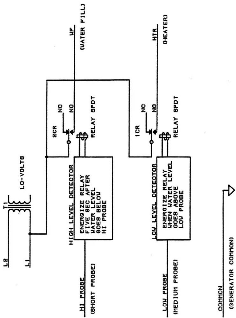
The Cleveland Range water level control, P/N 23198, is designed to maintain operating water level in Cleveland Range steam generators and to ensure that the heat source is only operated when the generator water level is above a specified minimum level. The sensing technique for the control relies on the fact that tap water is conductive to electricity; if two metal electrodes are immersed in a bath of water, electric current can flow between the electrodes using the water as a conductor. Water is not a good conductor, like copper, but is conductive enough to be measured using appropriate electronic circuitry.
The Cleveland Range control is a two probe system having two metallic probes (LOW and HI) for sensing water in the generator; a COM terminal is placed on the tank. The LOW probe is placed so that it will come in contact with the water when the water level is just above the desired water level, enough to protect the heat source. If the water is of sufficient level and the LOW probe is in the water, a small electrical current provided by the level control electronics will flow between the probe and COM; this flow will be sensed by the electronics which in turn will activate the "HEAT" relay to apply AC power to the HEAT terminal on the control circuit board.
Similarly, the HI probe is located at the desired water level fill (above the LOW probe level) so that when the water level has reached the desired fill level electrical current will flow between the HI probe and COM. The action of this probe is reversed from the previous situation so that when water reaches the HI probe, the WATER fill relay is deactivated so that AC power to the WF is turned off. When the water level drops below the HI probe, the WF terminal will be re-energized after a five second delay. The time delay is to prevent bubbling or turbulence in the generator from chattering to WATER fill relay or the water valve solenoid.
The control runs on 120 vac and is transformer isolated so that the probes and the electronics are run at low voltage and are not common to the AC power line.
Note that in many Cleveland Range generators both sensing probes are inserted from the front top of the unit down into the generator. In this case, the LOW probe will be the longest and the HI probe will be the shortest.
A) SYMPTOMS OF WATER LEVEL CONTROL RELATED PROBLEMS:
1) Boiler overfills or floods
2) Boiler dry fires (system underfills or doesn't fill)
3) Boiler doesn't fill at all
4) Water fill solenoid chatter
5) Heater contactor chatter
6) Fills but cuts out on LOW WATER before filling again
7) Overfills but does not heat
8) Fills but does not heat
B) POSSIBLE CAUSES:
1) Inoperative water level control circuit board (P/N 23198)
2) Incorrect or damaged wiring to probes
3) Incorrect or damaged wiring from water level board to loads
4) Damaged probes
5) Probes shorted together
6) Scale build-up on probes
C) FAULT ISOLATION PROCEDURE:
Equipment Required: Volt/Ohmmeter (VOM) or Multimeter
| STEP | TEST | RESULT | REMEDY |
| 1. | Is power applied to the control circuit board? Measure L1-L2 at the board to be 120 VAC ± 15V. | Yes | Go to Step #2 |
| No | Correct external supply problem | ||
| 2. | Remove two AC power wires from control board and connect ohmmeter to control board power terminals. Is resistance between 100-1000 ohms? | Yes | Reconnect power and go to Step #3 |
| No | Replace control board P/N 23198 (inoperative transformer) | ||
| 3. | Visually inspect probe wiring for damaged or broken wires or loose or missing terminals at either end. Is wiring visually OK? | Yes | Go to Step #4 |
| No | Replace wiring as required | ||
| 4. | Are the following connections made correctly? | Yes | Go to Step #5 |
| A) COM input on board to boiler ground | No | Correct probe wiring as required (see Figure 1) | |
| B) LO input on board to long length "LO" probe | |||
| C) HI input on board to short "HI" probe | |||
| 5. | Temporarily disconnect the wire from the HTR terminal so that the heat source will not operate. Is the heat source off? | Yes | Go to Step #6 |
| No | Check heat source and wiring in cooker | ||
| 6. | With HTR still disconnected, disconnect the LOW wire at the LOW terminal of the control board. Measure the AC line voltage between the HTR and L2 terminals on the control board. Is the voltage 0 vac? NOTE: Digital meters may read a few volts due to their high input impedance; this should be considered as 0 vac. | Yes | Go to Step #7 |
| No | Replace water level control P/N 23198 | ||
| 7. | Short the LOW and COM terminals on the control board. Does the AC line voltage between the HTR and L2 terminals now read 120 vac (line voltage)? | Yes | Reconnect HTR & LOW wires and go to Step #8 |
| No | Replace water level control P/N 23198 | ||
| 8. | Disconnect the wires from the HI and COM terminals on the control board and short the HI & COM terminals together. Measure the AC line voltage between the WF and L2 terminals. Is the voltage 0 vac? | Yes | Go to Step #9 |
| No | Replace water level control P/N 23198 | ||
| 9. | Remove the short from the HI and COM terminals on the control board. Does the AC line voltage between WF and L2 stay at 0 vac for about five seconds, then jump to 120 vac? | Yes | Reconnect HI & COM wires and go to Step #10 |
| No | Replace water level control P/N 23198 | ||
| 10. | Drain all water form the generator. Disconnect the wires from the LO, HI, & COM terminals at the control board. Connect an Ohmmeter across the LO and COM wires leading to the generator. Does the Ohmmeter read greater than 100,000 ohms? | Yes | Go to Step #12 |
| No | Go to Step #11 | ||
| 11. | Disconnect the LO wire at the water sensing probe on the generator. Does the Ohmmeter connected in the previous step now read greater than 100,000 ohms? | Yes | Go to Step #12 |
| No | Replace probe wiring | ||
| 12. | Reconnect the ohmmeter across each end of the disconnected LO wire. Does the ohmmeter read less than 10 ohms? | Yes | Go to Step #13 |
| No | Replace wire | ||
| 13. | Connect an ohmmeter across the HI and COM wires leading to the generator. Does the ohmmeter read greater than 100,000 ohms? | Yes | Go to Step #15 |
| No | Go to Step #14 | ||
| 14. | Disconnect the HI wire at the water sensing probe on the generator. Does the ohmmeter connected in the previous step now read greater than 100,000 ohms? | Yes | Replace probe wiring |
| No | Go to Step #16 | ||
| 15. | Reconnect the ohmmeter across each end of the disconnected HI wire. Does the ohmmeter read less than 10 ohms? | Yes | Go to Step #16 |
| No | Replace probe wiring |
STEP
TEST
- Reconnect one lead of the ohmmeter to the COM wire at the control board and connect the other ohmmeter lead to generator ground. Does the ohmmeter read less than 10 ohms?
- Reconnect the ohmmeter across the LOW terminal at the sensing probe & generator ground. Does the ohmmeter read greater than 100,000 ohms?
- Reconnect the ohmmeter across the HI terminal at the sensing probe & generator ground. Does the ohmmeter read greater than 100,000 ohms?
- Remove probe and check for scale buildup on or across probes. Replace probe assembly as required.
RESULT
REMEDY
Yes Reconnect HI, LOW & COM wires at control board only. Go to Step #17.
No Replace probe wiring
Yes Go to Step #18
No Replace probe assembly
Yes Go to Step #19
No Replace probe assembly
TG/dr1
02898
flowchart
graph TD
    A["LO-VOLT8"] --> B["2CR"]
    B --> C["RELAY SPDT"]
    C --> D["(WATER FILL)"]
    E["HI PROBE (SHORT PROBE)"] --> F["ENERGIZE RELAY\nFIVE SEC AFTER\nWATER LEVEL\nGOES BELOW\nHI PROBE"]
    G["LOW PROBE (MEDIUM PROBE)"] --> H["ENERGIZE RELAY\nWHEN WATER LEVEL\nGOES ABOVE\nLOW PROBE"]
    I["RELAY SPDT"] --> J["1CR"]
    J --> K["RELAY SPDT"]
    L["HTR (HEATER)"] --> M["RELAY SPDT"]
    N["COMMON (GENERATOR COMMON)"] --> O["↓"]
FIGURE 1 TWO-PROBE & COMMON WATER LEVEL CONTROL
The following is an alphabetical listing of regional distributors of parts and service throughout the United States and Canada. Contact your nearest distributor for the name of an Authorized Service Agency in your area.
-
ACME AMERICAN REPAIRS 99 SCOTT AVENUE BROOKLYN NY 11237 (718)456-6544 1-800-221-3026 (NY)
-
AMERICAN KITCHEN MACHINE 204 QUARRY STREET PHILADELPHIA PA 19106 (215)627-7760 1-800-848-7760
-
ARMSTRONG REPAIR CENTER 5750-A ROYALTON HOUSTON TX 77081 (713)666-7100 1-800-392-5325 (TX) 1-800-231-0822 (AR, KS, LA, MS, MO, OK)
-
APPLIANCE INSTALLATION & SVC 2464 MAIN STREET BUFFALO NY 14214 (716) 836-8606 1-800-252-2535
-
AUTHORIZED COMMERCIAL SERVICE 1938 EAST OSBORN ROAD PHOENIX AZ 85016 (602) 234-2443 1-800-824-8875(AZ)
-
AUTHORIZED FACTORY SERVICE 1010 FIRST AVENUE CORAPOLIS PA 15108 (412) 262-2130 1-800-222-8767(PA)
-
BANA PARTS INC 1501 KUEBEL STREET HARANAN LA 70123 (504) 734-0076
-
BRESSIE ELECTRIC CO 7413 MOSSY CUP STREET BOISE ID 83709 (208) 362-2333 1-800-362-0470(ID)
-
BROWLEY PARTS & SERVICE 806 IZARD STREET LITTLE ROCK AR 72201 (501) 374-0281 1-800-482-9269 (AR)
-
BCSI 3121 NW 16TH TERRACE POMPANO BEACH FL 33064 (305)971-0456
-
BURNEY'S COMMERCIAL SERVICE 4480 ALDEBARON AVENUE LAS VEGAS NV 89103 (702) 736-0006 1-800-634-7600 (NV)
-
CAC, INC 610 INDUSTRIAL AVENUE NE ALBUQURQUE NM 87102 (505)343-6100 1-800-366-8242
-
CASCO FOOD EQUIP SVC INC 10 DUNKLEE ROAD BOW NY 03304 (603)224-9173
-
CERTIFIED SERVICE CENTER 4946-50 PADDOCK ROAD CINCINNATI OH 45237 (513) 242-3139 (OH) 1-800-543-2060 (NATIONAL) 1-800-583-0799 (OH)
-
COMMERCIAL APPLIANCE PARTS 3501 2ND AVENUE SACRAMENTO CA 95817 (916)739-1192
-
COMMERCIAL APPLIANCE SERVICE 2101 M HILLSBOROUGH AVENUE TAMPA FL 33603 (813) 879-2461 1-800-282-4718 (FL)
-
COMMERCIAL KITCHEN REPAIR 1377 N BRAZOS SAN ANTONIO TX 78207 (512) 735-2011 (512) 735-5249 1-800-292-2120(TX)
-
COMMERCIAL PARTS & SERVICE 1150 WEST MOUND STREET COLUMBUS OH 43223-2295 (614) 221-0057
-
COMMERCIAL PARTS & SERVICE 5310 EAST 25TH STREET PO BOX 18688 INDIANAPOLIS IN 46218 (317) 545-9655 1-800-727-8710
-
COMMERCIAL PARTS & SERVICE 3717 CHERRY ROAD MEMPHIS TN 38118 1-800-974-9155
-
COMMERCIAL PARTS & SERVICE 470 WOODYCREST NASHVILLE TN 37210 (615) 244-8050 1-800-831-7174
-
CONES REPAIR SERVICE 2408 40TH AVENUE MOLINE IL 61265 (309) 797-5323 1-800-447-6761 (NATIONAL)
-
DAUBERS INC 7645 DYNATECH COURT SPRINGFIELD VA 22153 (703) 866-3600
-
DUFFY'S EQUIPMENT SERVICE 3138 ONEIDA STREET SAUQUOIT NY 13456 (315) 737-9401 1-800-443-8339(NY)
-
EICHENAUER SERVICES 130 S OAKLAND STREET DECATUR IL 62522 (217) 429-4229 1-800-252-5892(IL) 1-800-342-0240(NATIONAL)
-
ELECTRICAL APPLIANCE REPAIR 5805 VALLEY BELT ROAD INDEPENDENCE ON 44131 (216) 459-8700 1-800-621-8259 (OH)
-
ELECTRIC MOTOR REPAIR 700 EAST 25TH STREET BALTIMORE MD 21218 (410)407-8080
-
ELMER SCHULTZ SERVICES 540 NORTH THIRD STREET PHILADELPHIA PA 19123 (215) 627-5400
-
FOOD EQUIP PARTS & SERVICE 300 PUNHALE ROAD HONOLULU HI 96819 (808) 847-4871
-
GENERAL PARTS & SERVICE 6633 W NATIONAL AVENUE MILMAUKEE WI 53214 (414)257-4008
-
GCS SERVICE INC 110 GIANT AVENUE SUITE B RICHMOND VA 23224 (804) 232-3272
-
GCS SERVICE INC 9030 KENAMOR DRIVE SUITE 314 SAN DIEGO CA 92121 (619) 549-8411 1-800-422-7278 (CA)
-
GCS SERVICE INC 946 EAST 12TH STREET LOS ANGELES CA 90021 (213) 749-7785 1-800-327-1433 (CA)
-
GCS SERVICE INC 150 ASSOCIATED ROAD SO SAN FRANCISCO CA 94080 (415) 871-6693 1-800-255-6307(NV)
-
GCS SERVICE INC 696 LARCH AVENUE ELMHURST IL 60126 1-800-942-9689
-
GCS SERVICE INC 815 CAMBRIDGE STREET CAMBRIDGE MA 02141 (617) 426-8962 1-800-225-1155 (NATIONAL)
-
GCS SERVICE INC 21477 BRIDGE STREET SUITE B SOUTHFIELD MI 48034 (313) 354-5580 1-800-772-2936 (NATIONAL)
-
GCS SERVICE INC 2213 RIVER FRONT ROAD KANSAS CITY MO 64120 (816) 472-6477 1-800-821-7680(KS)
-
GCS SERVICE INC 9722 REAVIS PARK DRIVE ST LOUIS MO 63123 (314) 638-7444 1-800-392-3505(MO)
-
GCS SERVICE INC 5760 HAMPTON BLVD SUITE 106 VIRGINIA BEACH VA 23455 (804) 464-3500 1-800-621-0232 (VA) 1-800-1476-4278 (VA)
-
GCS SERVICE INC 292 MURPHY ROAD HARTFORD CT 06114 (203) 549-5575 1-800-523-7901(CT)
-
GCS SERVICE INC 1002 WATERMAN AVENUE E PROVIDENCE RI 02914 (401) 434-6803 1-800-462-6241(RI)
-
GCS SERVICE INC 932 GRAND STREET BROOKLYN NY 11211 (718) 486-5220 1-800-969-4271 (NATIONAL)
-
GCS SERVICE INC 3273 NW 168TH STREET MIAMI FL 33056 (305) 621-6666(DADE COUNTY) 1-800-766-8966(FL)
-
GCS SERVICE INC 4305 VINELAND ROAD SUITE 612 ORLANDO FL 32811 (407) 841-2551 OR 2552 (407) 423-8425 FAX 1-800-338-7322 (FL)
-
GCS SERVICE INC 5001 COLLEGE AVENUE COLLEGE PARK MD 20740 (301) 927-7330(DC) 1-800-638-7278(NATIONAL)
-
GOODWIN/TL : ? GROUP INC 815 N 19TH : :REET OMAHA NE 68102 1-800-345-7400
-
HAGAR REST EQUIP SERVICE 1229 WEST MAIN OKLAHOMA CITY OK 73106 (405) 235-2184 1-800-522-3706 (OK) 1-800-445-1791 (NATIONAL)
-
HAWKINS COMM APPL SERVICE 3000 S MYANDOT ENGLEWOOD CO 80110 1-800-624-2117
-
INDUSTRIAL ELECTRIC 5662 ENGINEER DRIVE HUNTINGTON BEACH CA 92649 (714) 379-7100
-
JACKSON PASPRAY SERVICE 155 SARGENT AVENUE CLIFTON NJ 07013 (201) 471-8000 1-800-356-6740
-
JONES-MCLEOD APPLIANCE SVC 1616 7TH AVENUE NORTH BIRMINGHAN AL 35203 (205) 251-0159 1-800-821-1150(AL) 1-800-231-5832(GA,FL, MS,TN)
-
K & D SERVICE 1833-41 N CAMERON STREET HARRISBURG PA 17103 (717) 236-9039 1-800-932-0503 (PA)
-
LAMONICA REST EQUIP SVC 6182 SOUTH STRATIER MURRAY UT 84107 (801) 263-3221
-
METRO APPLIANCE SERVICE 1640 & BROADWAY DENVER CO 80210 (303) 778-1126 1-800-525-3532 (CO)
-
METRO APPLIANCE SERVICE 10911 WEST HIGHWAY 55 MINNEAPOLIS MN 55441 (612) 546-4221 1-800-345-4221 (NATIONAL) 1-800-345-3508 (MN)
-
NORTHERN PARTS DISTRIBUTORS 171 & CATHERINE STREET PLATTSBURG NY 12901 (518) 363-3200 1-800-634-5005
-
P & D APPLIANCE SERVICE 333 SEVENTH STREET SAN FRANCISCO CA 94103 (415) 861-1414 1-800-424-1414 (CA)
-
RESTAURANT APPLIANCE SERVICE 7219 ROOSEVELT WAY NE SEATTLE WA 98115 (206) 524-8200 1-800-433-9390 (WA)
-
RON'S SERVICE 16364 SW 72ND AVENUE PORTLAND OR 97224 (503) 624-0890
-
SOUTHEASTERN REST SERVICE 2200 NORCROSS PARKWAY SUITE 210 ATLANTA GA 30071 (404) 446-6177 1-800-235-6516 (NATIONAL)
-
STATE WIDE SERVICE 603 MAIN AVENUE NITRO WV 25143 (304) 755-1811
-
STOVE PARTS SUPPLY CO 2120 SOLANA STREET FT WORTH TX 76117 (817) 831-0381 1-800-433-1804 (NATIONAL) 1-800-772-7420 (TX)
-
SUMMIT RESTAURANT REP 272 ELMONT ROAD ELMONT NY 11003 1-800-675-7560
-
WELBILT PARTS & SERVICE 2248 DANCY TRAIL CLERMONT FL 34711 (813)920-8321
-
WHALEY ELECTRIC SERVICE I-26 AT U S 1 W COLUMBIA SC 29169 (803) 791-4420 1-800-845-9382 (NC)
- Installation and Operation Manual
- Cleveland STATEMENT OF POLICIES
- LIMITED WARRANTY
- LIMITED EXTENDED WARRANTY COVERAGE
- INSTALLATION INSTRUCTIONS
- STEAMERS, STEAMER/KETTLES, MODULAR BOILER BASES, and KETTLES ON BOILER BASES
- Cleveland Range, Inc.
- INSTALLATION INSTRUCTIONS FOR STEAMERS, STEAMER/KETTLES, MODULAR BOILER BASES, and KETTLES ON BOILER BASES
- WARNING
- INSTALLATION INSTRUCTIONS FOR ALL MODELS
- For Gas-Fired Steam Generators:
- For Electric-Powered Steam Generators:
- For Steam Coil Steam Generators:
- For Direct-Steam-Connected Steamers/Kettles:
- (Continued)
- CLEVELAND
- INSTALLATION INSTRUCTIONS FOR DIRECT STEAM KETTLES
- INSPECTION
- SHIPPING DAMAGE INSTRUCTIONS
- INSTALLATION
- ASSEMBLY
- KDT-T SERIES (Table-Top Models)
- OF SERVICE CONNECTIONS
- STEAM
- CONDENSATE
- WATER
- FINAL INSTALLATION CHECK
- OPERATION
- CARE AND CLEANING
- WARNING: Do not use chlorine base detergent.
- STEAM CONTROL
- OPERATING CONTROLS
- ITEM NO. DESCRIPTION
- FUNCTION
- SERVICING GUIDE
- STEAM GENERATOR (2 PROBE TYPE) MAINTENANCE PROCEDURES
- WATER QUALITY REQUIREMENTS — 2-PROBE TYPE STEAM GENERATOR PROTECTION AND MAINTENANCE
- INSTRUCTIONS FOR CHEMICALLY DESCALING 2-PROBE TYPE STEAM GENERATORS
- Descaling Procedure for Two-Probe Steam Generators
- THESE INSTRUCTIONS ARE FOR USE WITH POWDERED SULFAMIC ACID ONLY.
- CAUTION
- Descaling Procedure (continued)
- WATER LEVEL CONTROL SYSTEM
- TROUBLESHOOTING AND REPAIR
Brand : Cleveland
Model : 36GM300
Category : Generator