
CID2RU16-20DB1 - Patch panel Panduit - Free user manual and instructions
Find the device manual for free CID2RU16-20DB1 Panduit in PDF.


| Product Type | Rackmount Patch Panel |
| Brand | Panduit |
| Model | CID2RU16-20DB1 |
| Rack Height | 2U (3.5 inches / 88.9 mm) |
| Number of Ports | 16 |
| Connector Type | RJ45 (Copper) or LC/SC (Fiber) - Verify in manual |
| Material | Steel chassis, black powder coat finish |
| Dimensions (H x W x D) | 3.5 in x 19 in x 1.2 in (89 mm x 483 mm x 30 mm) |
| Weight | 2.5 lbs (1.13 kg) |
| Mounting | Standard 19-inch rack, front or mid-mount |
| Operating Temperature | 32°F to 122°F (0°C to 50°C) |
| Compliance | RoHS, UL Listed |
| Included Accessories | Mounting screws, cable management bars (if applicable) |
| Maintenance | Wipe with a dry or slightly damp cloth; no solvents |
| Safety | No user-serviceable parts; disconnect cable before cleaning |
| Spare Parts & Repairability | Contact Panduit for replacement screws or panel cover |
Frequently Asked Questions - CID2RU16-20DB1 Panduit
User questions about CID2RU16-20DB1 Panduit
0 question about this device. Answer the ones you know or ask your own.
Ask a new question about this device
Download the instructions for your Patch panel in PDF format for free! Find your manual CID2RU16-20DB1 - Panduit and take your electronic device back in hand. On this page are published all the documents necessary for the use of your device. CID2RU16-20DB1 by Panduit.
USER MANUAL CID2RU16-20DB1 Panduit
Inlet Duct is designed for Cabinet with equipment mounting rails spaced at 29.2".
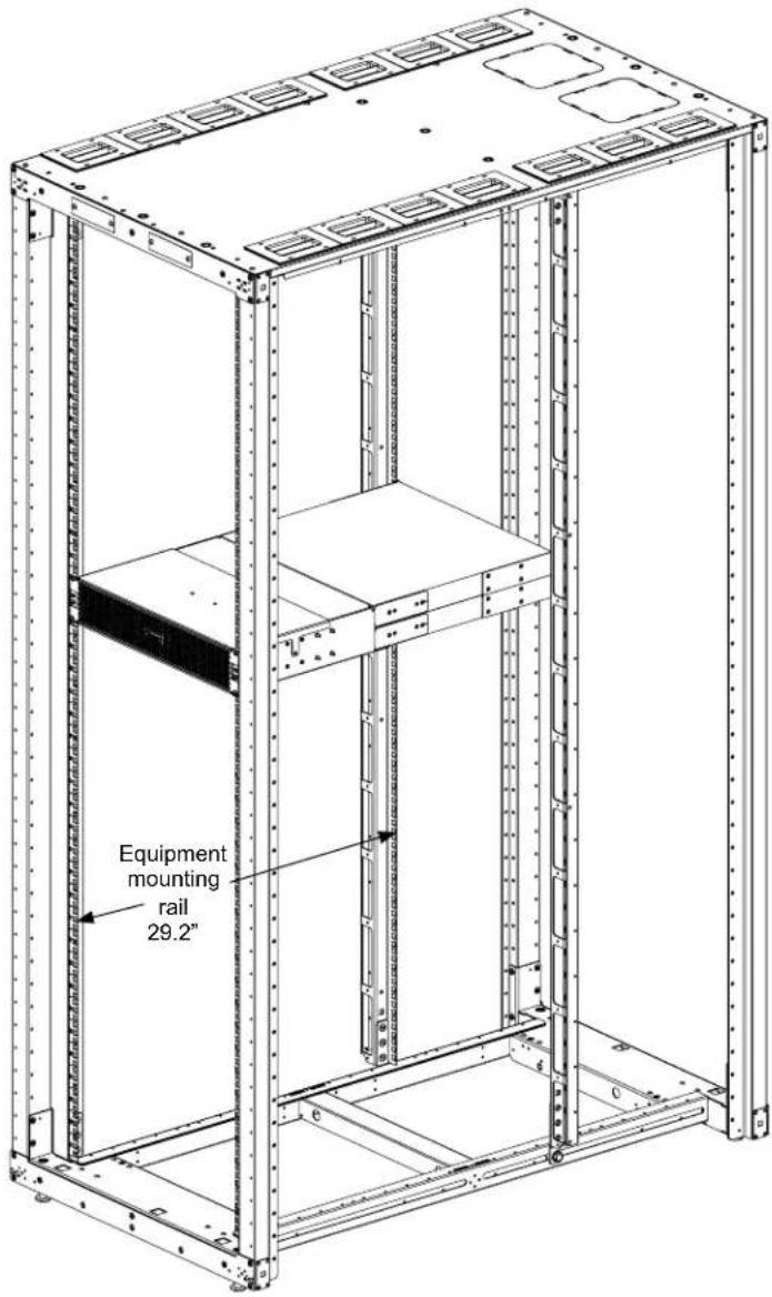
Inlet Duct includes:

natural_image
Technical line drawing of a rectangular electronic device housing with mounting flanges and internal components (no text or symbols)Inlet Duct Qty. 1

natural_image
Exterior view of a perforated plate with mesh texture and mounting brackets (no text or symbols on the plate itself)Front Perforated Plate Qty. 1

natural_image
Technical line drawing of a mechanical part labeled 'Rails Qty.4' (no other text or symbols)Hardware Included
| M3 x 0.5 x 8mm Flat Head Machine Screw 8x | M4 x 0.7 x 10mm Flat Head Machine Screw 8x | M5 x 0.8 x 12mm Button Head, Serrated Machine Screw 8x | M6 x 1 Cage Nut 4x | M6 x 1 x 15mm Round Head Screw 4x | #12-24 Bonding Cage Nut Kit 4 of each | 90° Flap Seal with 1.75" Flap Length 1x |
| [84x4] |
For Technical Support: www.panduit.com/resources/install_maintain.asp
Install Bonding Cage Nuts into the front equipment mounting rails at the desired RU location

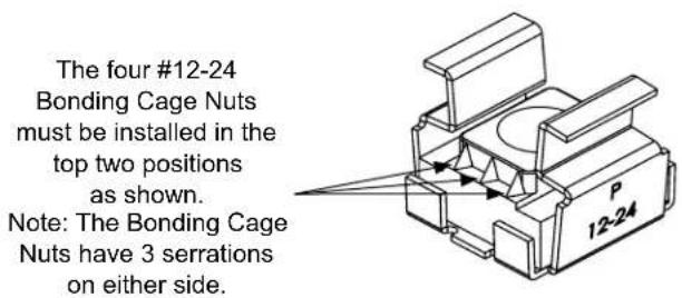

flowchart
graph TD
    A["Locations for the #12-24 Bonding Cage Nuts 4X"] --> B["Box 1"]
    A --> C["Box 2"]
    D["Locations for the M6 x 1 Cage Nuts 4X"] --> E["Box 3"]
    D --> F["Box 4"]
Install Inlet Duct onto the front equipment mounting rails
![M6 x 1 x 15mm Round Head Screw 4X tighten the two top screws only at this time. Torque specifications: 7.3 N·m [65 in·lbs] DO NOT TIGHTEN the two bottom screws at this time.](/content/2026/05/1060072/images/af33742fd0a5ffcaf89a391f6b791203a3bca004c9b4bf96b8f82f3a13e11b9d.jpg)

natural_image
Technical line drawing of a server rack cabinet frame (no text or symbols)For Technical Support: www.panduit.com/resources/install_maintain.asp
Replace Switch Rails with the Rails provided
1
1RU Switch (Not Included)
For reference only.

natural_image
Technical line drawing of a mechanical device with mounting flanges and a rectangular base (no text or symbols)②
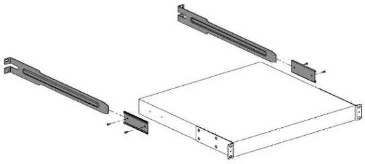
Remove the Rear Brackets from the switch. Note the size of screws that Rear Brackets are currently attached with. Provided Rails will be attached with the provided screws of same size.
natural_image
Technical diagram of a mechanical assembly with two metal brackets and a central rectangular component (no text or symbols)34
Install the provided Rails. Assure that the tapered ends are facing inward.
![Screw size option 1: M3 x 0.5 x 8mm Flat Head Machine Screw 4x Torque specifications: 1.0 N·m [9 in·lbs]](/content/2026/05/1060072/images/70bca1b9b1edf3239484a31b009410f282bb2281be42fd7b17a3644f6efde72b.jpg)
O
A total of two Switches can be installed into the Inlet Duct. Rails are provided for a total of two Switches.

natural_image
Technical line drawing of a rectangular electronic device with mounting flanges and a central panel (no text or symbols)![Screw size option 2 Screw size option 2: M4 x 0.7 x 10mm Flat Head Machine Screw 4x Torque specifications: 2.2 N·m [19 in·lbs]](/content/2026/05/1060072/images/8b4191e3f1c425cc63d917a7a308cf2cbb75c08ec624d2ec1f77adeee33599b6.jpg)
For Technical Support: www.panduit.com/resources/install_maintain.asp
Install switch(s) into Inlet Duct
Slide the Switch into the Inlet Duct.
For single Switch application, Switch must be installed on the lower level of Inlet Duct.
Secure the Switch's Front Brackets to the rear equipment mounting rail (Hardware not Included)
Align the slots on the Rails to the threaded holes on the Inlet Duct.

![M5 x 0.8 x 12mm Button Head, Serrated Machine Screw 8x Torque specifications: 5.1 N·m [45 in·lbs]](/content/2026/05/1060072/images/921b0030bfc20ea210cc74f922b145e1ca314c2ab70605c09eaf96fed21b9b38.jpg)
For Technical Support: www.panduit.com/resources/install_maintain.asp

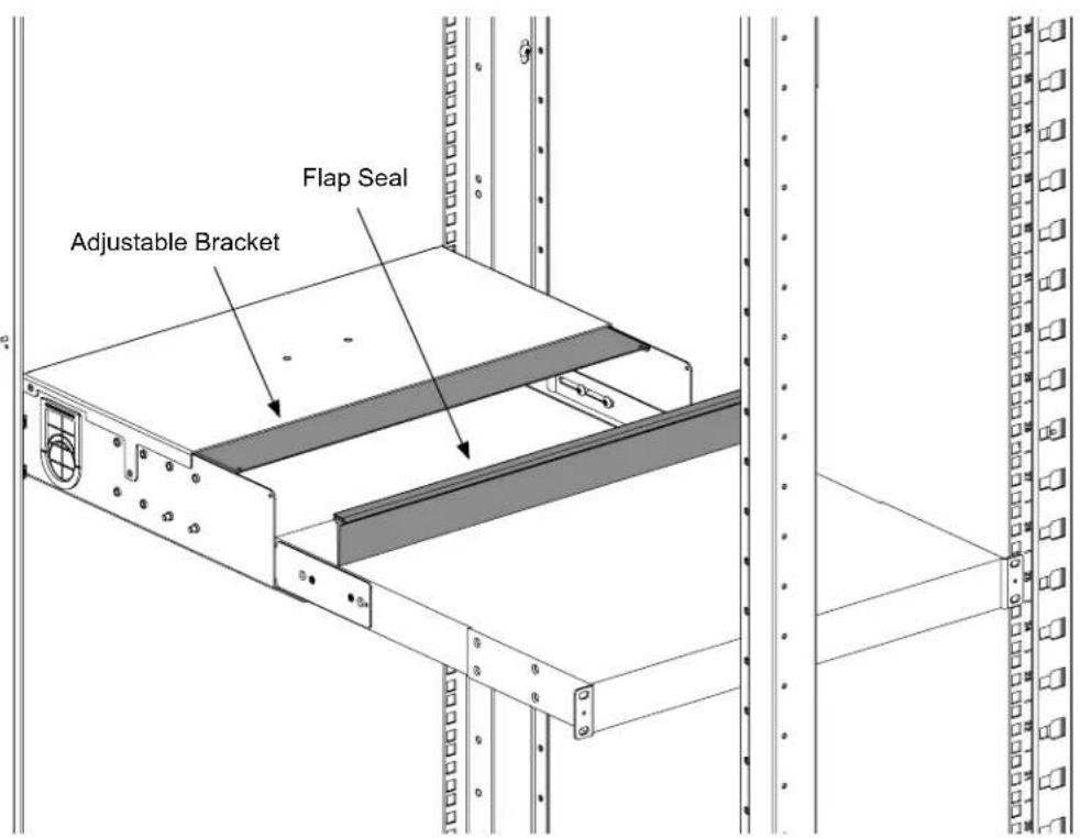
Move the Adjustable Bracket until its edge aligns with the rear of the Switch.
Attach the Flap Seal to the edge of the Adjustable Bracket to close off the open space.
For Technical Support: www.panduit.com/resources/install_maintain.asp
Inlet Duct with one Switch installed.

Repeat Switch installation steps for a two Switch application. Discard Flap Seal.

natural_image
Technical line drawing of a server rack cabinet with mounting holes and drive bays (no text or labels)For Technical Support: www.panduit.com/resources/install_maintain.asp
![Tighten the Wing Nuts that are located inside the Inlet Duct. 2 places. Reference Torque specifications: 3.7 N·m [33 in·lbs]](/content/2026/05/1060072/images/6eaca7529afb7c3ac90555dd4363c965acf236234a62e9b9b5ee3f7c7baef9ac.jpg)
Cable Routing Option
Cables can be routed through Power Grommets on either side of the Inlet Duct.
Use a Utility Knife to slit Power Grommets along guides.
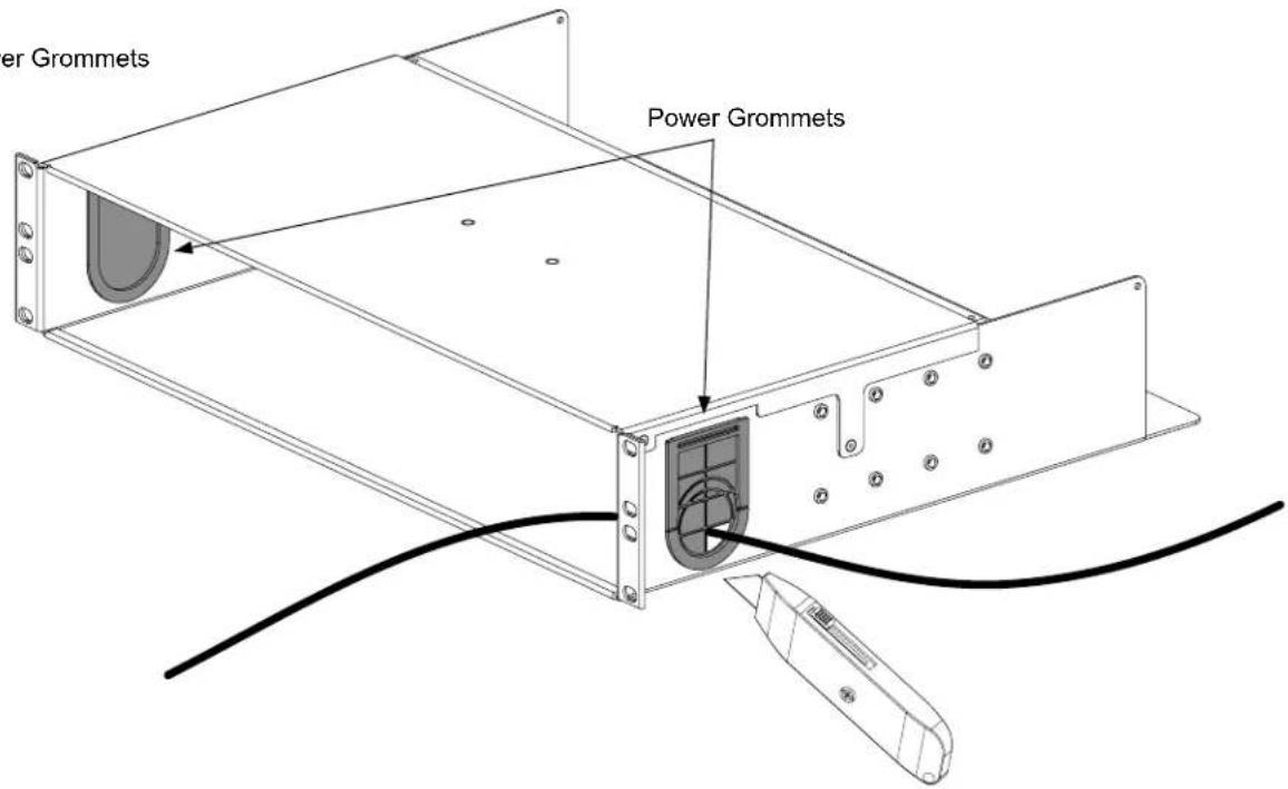
For Technical Support: www.panduit.com/resources/install_maintain.asp
Install Perforated Front Plate
Install the Perforated Front Plate over the two bottom M6 x 1 x 15mm screws that were previously left loose.
Rotate the Perforated plate in place by tucking the Top Flange into the Inlet Duct.

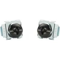
Install the four #12-24 Grounding Screws into the Grounding Cage Nuts and tighten.
Also tighten the two bottom M6 x 1 x 15mm screws that were previously left loose.
12-24 Grounding Screws 4x
Torque specifications: 5.1 N·m [45 in·lbs]
![M6 x 1 x 15mm 2x Torque specifications: 7.3 N·m [65 in·lbs]](/content/2026/05/1060072/images/2f08bde8f7141bc128400209d58ca7740c801cd946a4ec705ab2c07cfedf9222.jpg)
For Instructions in Local Languages and Technical Support:
www.panduit.com/resources/install_maintain.asp

www.panduit.com
E-mail: techsupport@panduit.com
Phone: 866-405-6654
- Install Bonding Cage Nuts into the front equipment mounting rails at the desired RU location
- Install Inlet Duct onto the front equipment mounting rails
- Replace Switch Rails with the Rails provided
- Install switch(s) into Inlet Duct
- Cable Routing Option
- Install Perforated Front Plate
- 12-24 Grounding Screws 4x
Brand : Panduit
Model : CID2RU16-20DB1
Category : Patch panel