
BLEA595 - Electrical switch JUNG - Free user manual and instructions
Find the device manual for free BLEA595 JUNG in PDF.


| Product Type | Blind Actuator |
| Model | BLEA595 |
| Brand | JUNG |
| Dimensions | 45 x 45 x 30 mm |
| Weight | 0.1 kg |
| Power Supply | 230 V AC, 50 Hz |
| Rated Load | 6 A |
| Operating Temperature | -10°C to +40°C |
| Protection Rating | IP20 |
| Connection | Screw terminals |
| Functions | Up/Down/Stop control, intermediate positions, time control |
| Maintenance | Clean with dry cloth |
| Safety | Overload protection |
| Spare Parts | Available from JUNG service |
| Compatibility | Standard flush-mounted boxes |
| Certification | CE, VDE |
Frequently Asked Questions - BLEA595 JUNG
User questions about BLEA595 JUNG
0 question about this device. Answer the ones you know or ask your own.
Ask a new question about this device
Download the instructions for your Electrical switch in PDF format for free! Find your manual BLEA595 - JUNG and take your electronic device back in hand. On this page are published all the documents necessary for the use of your device. BLEA595 by JUNG.
USER MANUAL BLEA595 JUNG
Bluetooth Low Energy radio transmitter
GB
Ref.-no.: BLE A 590 .., BLE LS 990 .., BLE .. 2990-L
BLE A 595 .., BLE LS 995 .., BLE .. 2995-L
Operating instructions
1 Safety instructions

Electrical devices may only be mounted and connected by electrically skilled persons.
Serious injuries, fire or property damage possible. Please read and follow manual fully.
The radio communication takes place via a non-exclusively available transmission path, and is therefore not suitable for safety-related applications, such as emergency stop and emergency call.
These instructions are an integral part of the product and must remain with the end customer.
2 Device components
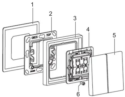
Fig. 1: Device components
(1) Adhesive film
(2) Holder plate
(3) Frames (not included in delivery)
(4) Radio module
(5) Rockers
(6) Retaining screw

Fig. 2 and fig. 3: Transport lock and protective film
(7) Transport lock for rockers
(8) Protective film for holder plate
3 Function
Intended use
- Smart switch for wireless device control using wireless standard Bluetooth Low Energy (BLE)
- For switching, dimming and controlling individual light scenes
- Mounting on appliance box according to EN 60670-1, screw fixing on walls or adhesive fixing on smooth, even surfaces (glass). Adhesive film included.
Product characteristics
- Battery-free device without external power supply
- Transmitting energy is generated from mechanical energy of actuation (energy harvesting)
- Encrypted transmission with AES-128 (CBC mode) and sequence counter
- Compatible with various wireless Bluetooth systems (up-to-date list on our website)
- Configuration interface: NFC Forum Type 2 Tag (ISO/IEC 14443 Part 2 + 3)
- Automatic range extension (depending on the system) via BT Mesh devices connected to the mains
4 Information for electrically skilled persons
Installation and electrical connection

DANGER
Electrical shock on contact with live parts in the installation environment.
Electrical shocks can be fatal.
Before working on the device, disconnect the power and cover live parts in the area!
Installation location
The radio range in buildings is approx. 10 m without wall penetration.
A wall penetration is not recommended, because it attenuates the radio signal too much.

Fig. 4: Installation location
In that case, the receiver may not be able to receive the signal from the transmitter correctly
Metal parts at the installation site (e.g. metal door frames) or moisture (e.g. in outdoor areas) can also have a negative effect on the radio transmission.
Fitting the device
• Fix holder plate (2) with adhesive film (1) at the installation location. (see section „Adhesive fixing“)
Alternatively, screw the holder plate onto an appliance box or directly onto the wall.
Note marking „Top“
- Push frame (3) onto holder plate.
- Snap radio module (4) onto holder plate.
arrow on sticker (rear side of radio module) points upwards (or „O“ is up and „I“ is down).
- Optional: Secure the radio module with the enclosed screw (6).
- Snap on rockers (5).
Note marking „Top“.
The transport lock (7) behind the rockers must be removed beforehand. (fig. 2)
Adhesive fixing
Important:
The final strength of the adhesive is only reached after 24 hours.
• After gluing the holder plate, let the adhesive cure a little.
Important:
The installation location cannot be changed after the adhesive fixing.
- To test the range, carry out commissioning before adhesive fixing.
Prerequisite:
Surface is dry, clean, stable and even.
Suitable cleaning agents:
water, degreaser, glass cleaner, methylated spirit
Not suitable for cleaning:
Bath or all-purpose cleaner, aggressive detergents
- Remove the protective film from the back of the adhesive film (1).
- Stick the adhesive film aligned on the surface.
Press firmly for about 10 seconds. - Remove the protective film (8) for the holder plate (2).
Do not remove the remaining protective films. - Stick the holder plate onto the adhesive film.
5 Operation
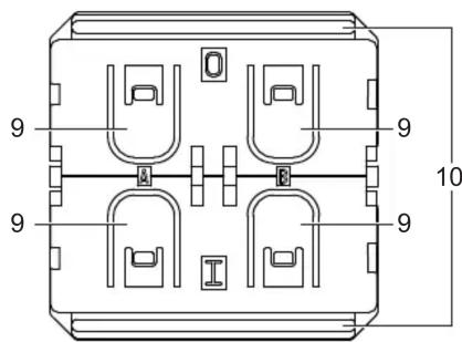
Fig. 5: Operation
Operating elements
The radio transmitter is operated either via one rocker (2-channel) or via two rockers (4-channel). There are four push-buttons (9) under the rockers. The push-buttons are grouped into two channels (A and B). A distinction is made between two states (I and O) for each channel.
The functions of the rockers (switching, push-button, dimming or blind) are not configured in the factory settings of the device.
Factory settings/Reset
Restoring factory settings:
- Remove rockers (5) carefully with a suitable tool (e.g. button lever).
- Press all four push-buttons (9) and the activation bar (10) simultaneously for at least 10 seconds. (fig. 5) Factory settings are restored automatically.
The radio transmitter is no longer taught-in.
Rockers are without function.
- Snap rockers on again.
6 Commissioning
The commissioning of the radio transmitter depends on the receiver used in the Bluetooth system. In the following description the commissioning is referred to as „teaching“ in the receiver. A channel of the radio transmitter can be taught-in in any number of receivers. After teaching, the receiver can clearly assign the signals of the transmitter.
Teaching-in the radio transmitter
The Bluetooth system used specifies the procedure for teaching. Usually, the system manufacturer provides an app for this purpose. The app explains the teaching procedure step by step. Two methods can be used for teaching:
- NFC chip
The chip is integrated in the radio module.
- QR code
The code is on a sticker on the back of the radio module.
Requirements:
- Radio network with receiver is ready for operation.
- Device with app and receiver are within range of the radio transmitter.
- App is installed.
7 Configuration
The functions of the rockers (switching, push-button, dimming or blind) depend on the Bluetooth system used and can be configured in the respective app.
The possible configurations depend on the number of channels or rockers:
- one rocker, 2-channel
- two rockers, 4-channel
8 Technical data
Radio frequency: 2.402 ... 2.480 GHz
Transmission range
in free field up to 75 m
in buildings approx. 10 m
Transmitting power 0.4 dBm / 1.1 mW
Ambient temperature -5 ... +45 °C
Storage/transport temperature -25 ... +65 °C
Atmospheric humidity 0 ... 95 % (no condensation)
9 Conformity
Albrecht Jung GmbH & Co. KG hereby declares that the radio system type art. no. BLE A 590 ..., BLE LS 990 ..., BLE .. 2990-L, BLE A 595 ..., BLE LS 995 ... and BLE .. 2995-L meets the directive 2014/53/EU. You can find the full article number on the device. The complete text of the EU Declaration of Conformity is available under the Internet address: www.jung.de/ce
10 Warranty
The warranty follows about the specialty store in between the legal framework as provided for by law.
- Bluetooth Low Energy radio transmitter
- Operating instructions
- Safety instructions
- Device components
- Function
- Intended use
- Product characteristics
- Information for electrically skilled persons
- Installation and electrical connection
- DANGER
- Installation location
- Fitting the device
- Adhesive fixing
- Operation
- Operating elements
- Factory settings/Reset
- Commissioning
- Teaching-in the radio transmitter
- Configuration
- Technical data
- Conformity
- Warranty
Brand : JUNG
Model : BLEA595
Category : Electrical switch