
PFR4K-D450 - Motion detector Dahua Technology - Free user manual and instructions
Find the device manual for free PFR4K-D450 Dahua Technology in PDF.


| Product Type | Security Radar Motion Detector |
| Brand | Dahua Technology |
| Model | PFR4K-D450 |
| Detection Range | Up to 450 m |
| Detection Technology | FMCW Radar |
| Video Resolution | Up to 4K (3840 × 2160) |
| Video Compression | H.265, H.264, H.264H, H.264B |
| Storage | MicroSD Card Slot (internal) |
| Network Interface | 10/100/1000 Mbps Ethernet (RJ-45) |
| Connectivity Protocols | TCP/IP, UDP, HTTP, RTSP, ONVIF, DDNS, PPPoE |
| PTZ Control | Supports linked PTZ camera control |
| Alarm Input/Output | 5 relay outputs, 1 alarm input |
| Smart Detection | Intrusion, tripwire, human/vehicle classification |
| Environment Modes | General, Shrub, Capacious |
| Power Supply | DC 12V or PoE (802.3af) |
| Security Features | Password protection, HTTPS, IP filter, account lock |
| Mounting | Wall or pole mount |
Frequently Asked Questions - PFR4K-D450 Dahua Technology
User questions about PFR4K-D450 Dahua Technology
0 question about this device. Answer the ones you know or ask your own.
Ask a new question about this device
Download the instructions for your Motion detector in PDF format for free! Find your manual PFR4K-D450 - Dahua Technology and take your electronic device back in hand. On this page are published all the documents necessary for the use of your device. PFR4K-D450 by Dahua Technology.
USER MANUAL PFR4K-D450 Dahua Technology
natural_image
Abstract geometric composition with gray and red color blocks (no text or symbols)Foreword
General
This manual introduces the functions and operations of the security radar.
Models
The following categorized signal words with defined meaning might appear in the manual.
| Signal Words Meaning | |
 WARNING WARNING | Indicates a medium or low potential hazard which, if not avoided, could result in slight or moderate injury. |
 CAUTION CAUTION | Indicates a potential risk which, if not avoided, could result in property damage, data loss, lower performance, or unpredictable result. |
 TIPS TIPS | Provides methods to help you solve a problem or save you time. |
 NOTE NOTE | Provides additional information as the emphasis and supplement to the text. |
Revision History
| Version | Revision Content | Release Time |
| V1.0.3 | Updated radar calibration, region management parameter, and protection zone management. | February 2023 |
| V1.0.2 | Added 240 m radar configuration. Changed figures. | March 2021 |
| V1.0.1 | Deleted previous Figure 4-64. | February 2020 |
| V1.0.0 | First release. | September 2019 |
About the Manual
- The manual is for reference only. If there is inconsistency between the manual and the actual product, the actual product shall prevail.
- We are not liable for any loss caused by the operations that do not comply with the manual.
- The manual would be updated according to the latest laws and regulations of related regions. For detailed information, see the paper manual, CD-ROM, QR code or our official website. If
there is inconsistency between paper manual and the electronic version, the electronic version shall prevail.
- All the designs and software are subject to change without prior written notice. The product updates might cause some differences between the actual product and the manual. Please contact the customer service for the latest program and supplementary documentation.
- There still might be deviation in technical data, functions and operations description, or errors in print. If there is any doubt or dispute, please refer to our final explanation.
- Upgrade the reader software or try other mainstream reader software if the manual (in PDF format) cannot be opened.
- All trademarks, registered trademarks and the company names in the manual are the properties of their respective owners.
- Please visit our website, contact the supplier or customer service if there is any problem occurred when using the device.
- If there is any uncertainty or controversy, please refer to our final explanation.
Important Safeguards and Warnings
The following contents are about the proper ways of using the radar, preventing dangers and property damage when it is in use. Read the manual carefully before using the radar, strictly abide by the manual and properly keep it for future reference.
Operation Requirements
- Do not place or install the radar in a place exposed to sunlight or near the heat source.
- Keep the radar away from dampness, dust or soot.
- Keep the radar installed horizontally on the stable place to prevent it from falling.
- Do not drop or splash liquid onto the radar, and make sure there is no object filled with liquid on the radar to prevent liquid from flowing into the device.
- Install the radar in a well-ventilated place, and do not block the ventilation of the device.
- Operate the radar within the rated range of power input and output.
• Do not disassemble the radar.
● Transport, use and store the radar under the allowed humidity and temperature conditions.
Electrical Safety
- Use the recommended power cables in your area and conform to the rated power specification.
- Use the power adapter provided with the radar; otherwise, it might result in people injury and device damage.
- The power source shall conform to the requirement of the Safety Extra Low Voltage (SELV) standard, and supply power with rated voltage which conforms to Limited power Source requirement according to IEC60950-1. Please note that the power supply requirement is subject to the device label.
- Connect the radar (I-type structure) to the power socket with protective earthing.
- The appliance coupler is a disconnection device. When using the coupler, keep the angle for easy operation.
Table of Contents
Foreword.... I
Important Safeguards and Warnings.... III
1 Network Configuration .... 1
1.1 Network Connection....1
1.2 Logging in to Web Client....1
1.2.1 Device Initialization....1
1.2.2 First-time Login....4
1.2.3 Forgetting Password....6
2 Live View 9
2.1 Encoding Configuration 9
2.2 Video Tool....9
2.3 Video Window Adjustment....10
2.4 System Menu ....11
2.5 Function Options ......11
2.6 Device List....12
2.7 PTZ Control....12
3 Playback.... 14
3.1 Video Playback....14
3.1.1 Playing Video....15
3.1.2 Record Types....16
3.1.3 Auxiliary Functions....16
3.1.4 Record Files .... 16
3.1.5 Clipping Records....17
3.1.6 Time Format of the Time Bar....18
3.2 Snapshot Playback....18
3.2.1 Playing Snapshots 19
3.2.2 Snapshot Files ....19
3.2.3 Snapshot Types....20
4 Setting....21
4.1 Radar....21
4.1.1 Video....21
4.1.2 PTZ Camera....27
4.1.3 Linkage 28
4.1.4 Region Management....32
4.1.5 Protection Zone Management ....35
4.1.6 IVS Setup 38
4.2 Network....38
4.2.1 TCP/IP 38
4.2.2 Port....41
4.2.3 PPPoE....43
4.2.4 DDNS 43
4.2.5 SMTP (Email) 44
4.2.6 UPnP 46
4.2.7 SNMP 47
4.2.8 Bonjour 49
4.2.9 Multicast....50
4.2.10 802.1x....51
4.2.11 QoS ....51
4.2.12 Access Platform....52
4.3 Event Management....53
4.3.1 Alarm 53
4.3.2 Abnormality 56
4.4 Storage....60
4.4.1 Schedule....60
4.4.2 Destination....63
4.4.3 Record Control....66
4.5 System....67
4.5.1 General....68
4.5.2 Date & Time....68
4.5.3 Account 70
4.5.4 Onvif User 74
4.5.5 Safety....75
4.5.6 Firewall....82
4.5.7 Default 84
4.5.8 Import/Export 85
4.5.9 Auto Maintain....85
4.5.10 Upgrade....86
4.6 Information....87
4.6.1 Version....87
4.6.2 Log....87
4.6.3 Remote Log....89
4.6.4 Online User....89
5 Alarm....90
6 Logging out 92
Appendix 1 Cybersecurity Recommendations....93
1 Network Configuration
Network Connection 1.1
There are mainly two connection methods between the radar and PC. See Figure 1-1 and Figure 1-2.
Figure 1-1 Connected by network cable
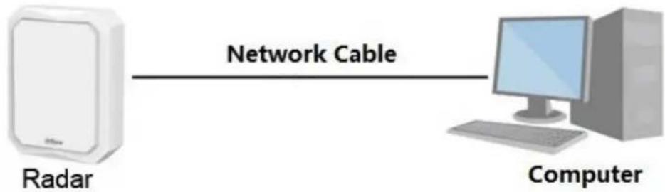
flowchart
graph LR
    A["Radar"] -->|Network Cable| B["Computer"]
Figure 1-2 Connected through router or switch
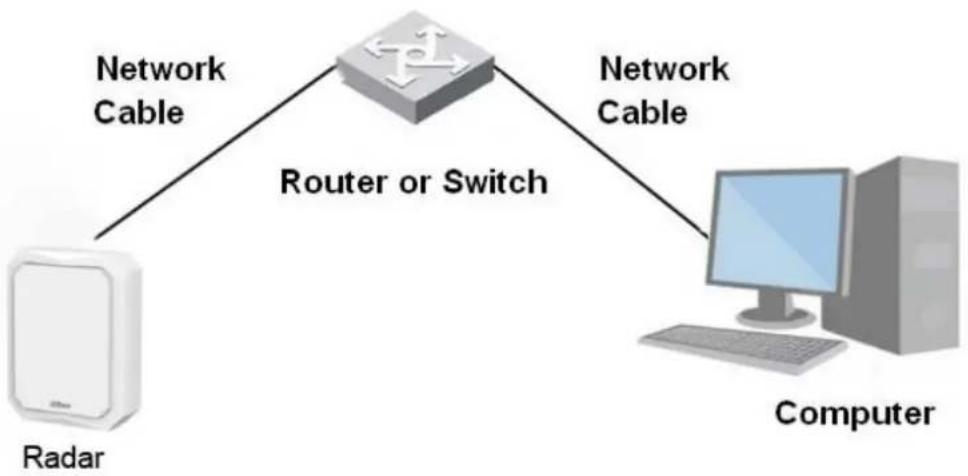
flowchart
graph TD
    A["Radar"] -->|Network Cable| B["Router or Switch"]
    B -->|Network Cable| C["Computer"]

The IP address of the radar is 192.168.1.108 by default. You need to use IP segment reasonably according to actual network environment so that the radar can connect to network.
1.2 Logging in to Web Client
1.2.1 Device Initialization
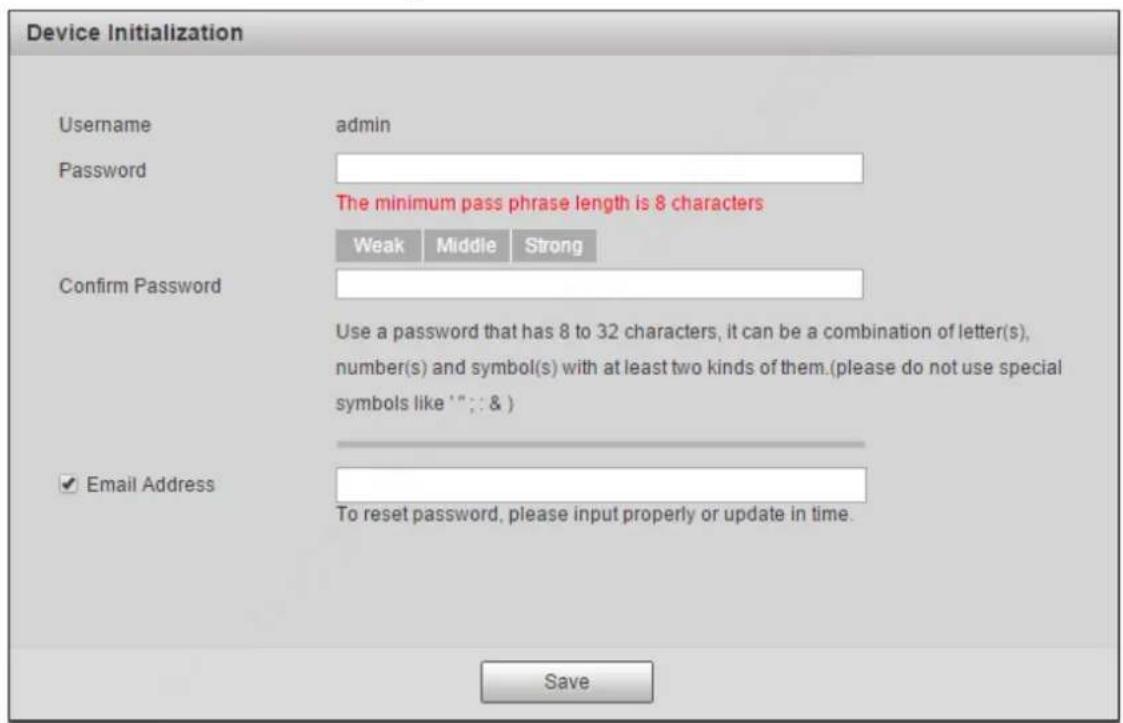
The radar needs to be initialized for the first-time use.
Step 1 Open IE browser, enter the IP address of the radar in the address bar, and then press Enter key.
After the radar is successfully connected, the Device Initialization interface is displayed. See Figure 1-3.
Figure 1-3 Device initialization
Step 2 Set the password. See Figure 1-4.

The password must consist of 8 to 32 non-blank characters and contain at least two types of characters among upper case, lower case, number, and special characters (excluding "";: &). Make sure that the password and the confirmed password are the same. Follow the password strength prompt to set a password with high security.
Figure 1-4 Set admin password
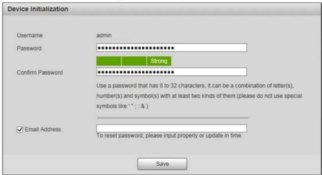
Step 3 (Optional) Set the email address which is used to reset password.

Email address function is enabled by default and you can disable it. We recommend you to enter the email address to guarantee normal use of the radar.
Step 4 Click Save.
The End-User License Agreement interface is displayed.
Step 5 Select I have read and agree to all terms check box, and then click Next.
Figure 1-5 P2P
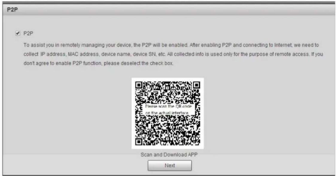
Step 6 Read on-screen notifications, select P2P check box as needed, and then click Next.
Figure 1-6 Online upgrade
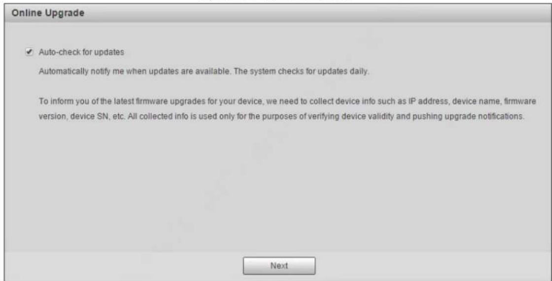
Step 7 Read on-screen notifications, select Auto-check for updates check box as needed, and then click Next.
The Country/Region Setting interface is displayed. See Figure 1-7.
Figure 1-7 Country or region setting
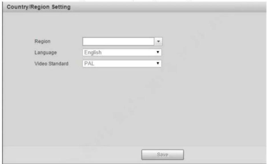
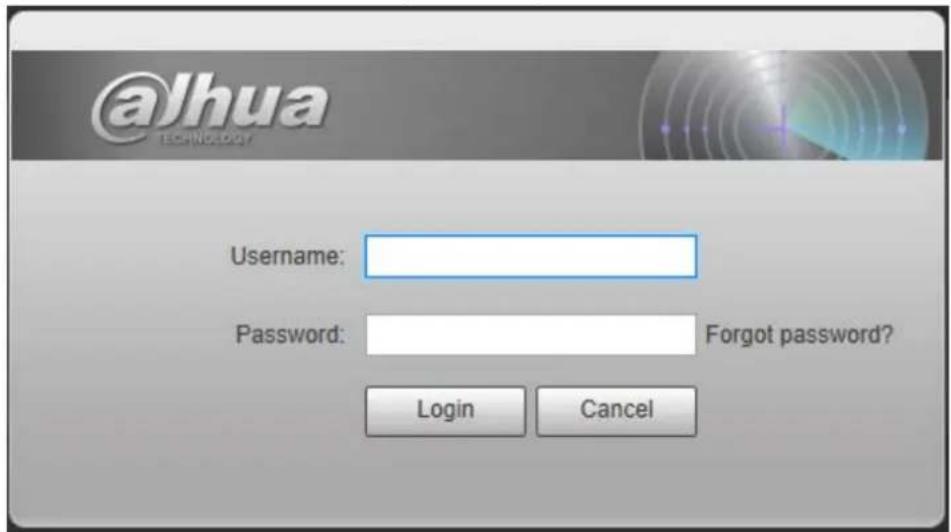
Step 8 Select region, language, and video standard as needed, and then click Save. The login interface is displayed. See Figure 1-8.
Figure 1-8 Login
1.2.2 First-time Login
You need to download and install the plug-in for the first-time login.
Step 1 Enter username and password, and then click Login.
The Live interface is displayed. See Figure 1-9.
Figure 1-9 Install the plug-in
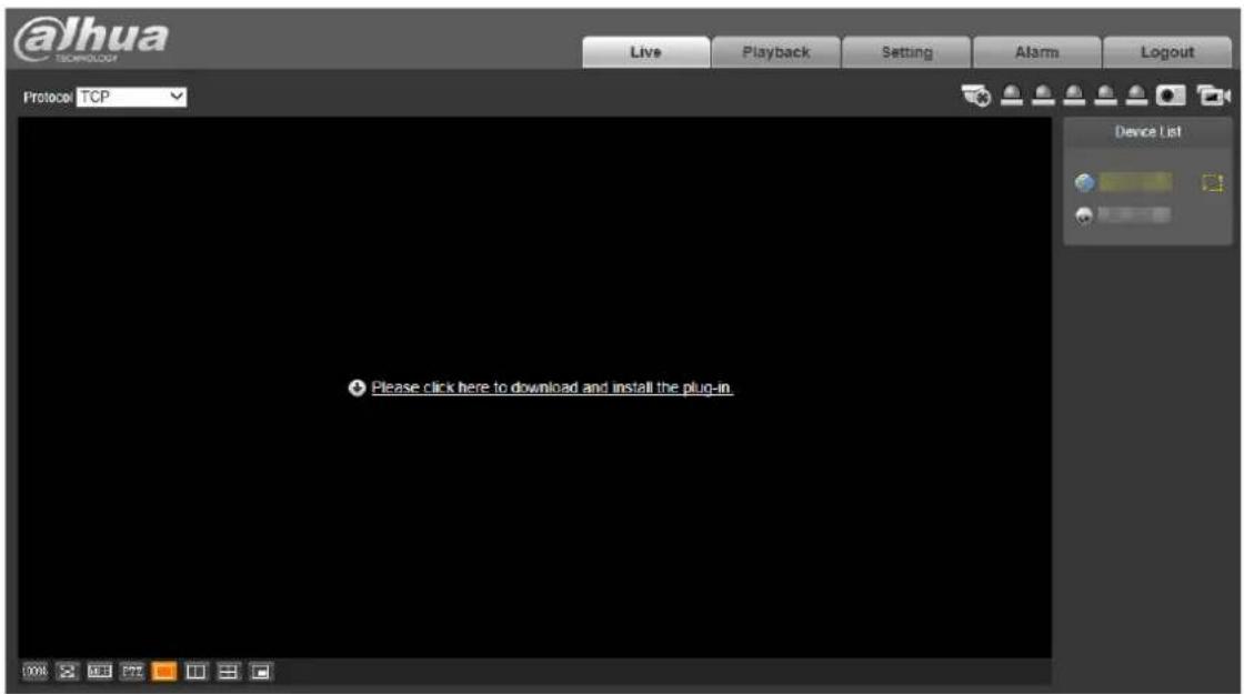

If you enter the wrong password for continuously 5 times, the account will be locked for 5 minutes. After the locked time ends, you can log in to the radar again. You can set the allowed wrong password times in Setting > Event > Abnormality > Illegal Access. For details, see "4.3.2.3 Illegal Access."
Step 2 Download and install the plug-in according to the on-screen instructions.
Step 3 After the plug-in is installed, the login interface is displayed automatically. Enter username and password, and then click Login.
The Live interface is displayed. See Figure 1-10.
Figure 1-10 Live
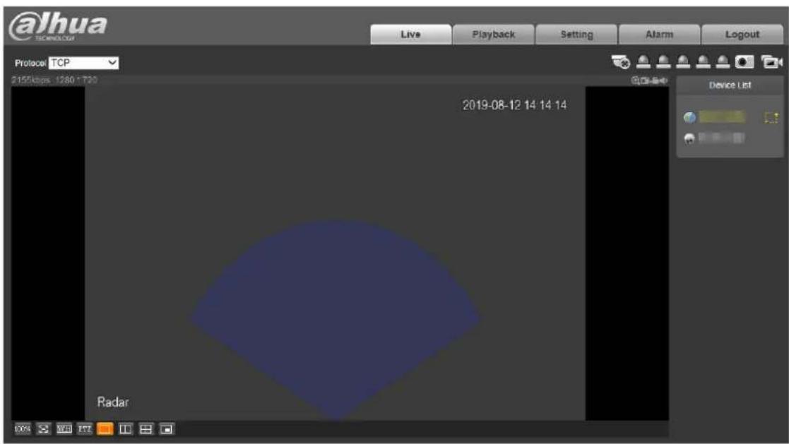

The Live interface might vary with different device models, and the actual interface shall prevail.
1.2.3 Forgetting Password
You can reset the admin password through the reserved email address when you forget it.
Step 1 Open IE browser, enter the IP address of the radar in the address bar, and then press Enter. The login interface is displayed. See Figure 1-11.
Figure 1-11 Login
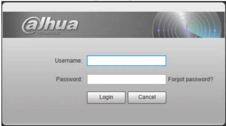
Step 2 Click Forgot password?
The Prompt interface is displayed. See Figure 1-12.
Figure 1-12 Prompt
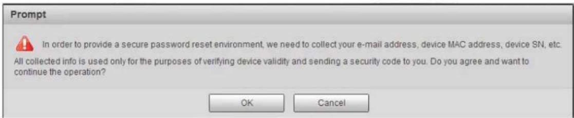
Step 3 Click OK.
The QR code scanning interface is displayed. See Figure 1-13.

After clicking OK, your information such as email address, MAC address, and device SN might be collected for authentication.
Figure 1-13 QR code
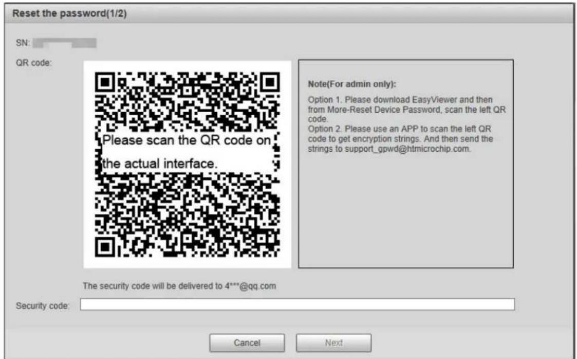
Step 4 Read notes and scan the QR code. Enter security code acquired from the reserved email and then click Next.
The password resetting interface is displayed. See Figure 1-14.

Reset the password within 24 hours after you get the security code; otherwise it will be invalid. If the security code is not used twice continuously, for the third time, the system will prompt that you fail to acquire the security code. For normal use of the radar, you need to restore the radar to default and then acquire the security code again, or acquire the security code after 24 hours.
Figure 1-14 Reset the password
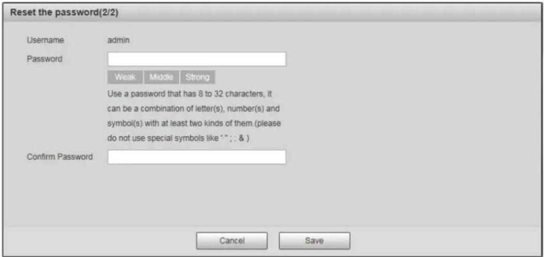
Step 5 Set the new admin password and then confirm it.

The password must consist of 8 to 32 non-blank characters and contain at least two types of characters among upper case, lower case, number, and special characters (excluding ""; &). Follow the password strength prompt to set a password with high security.
Step 6 Click Save.
The login interface is displayed.
2 Live View
You can do the operations such as watching live video, taking snapshots and records, and setting video stream.
Figure 2-1 Live view
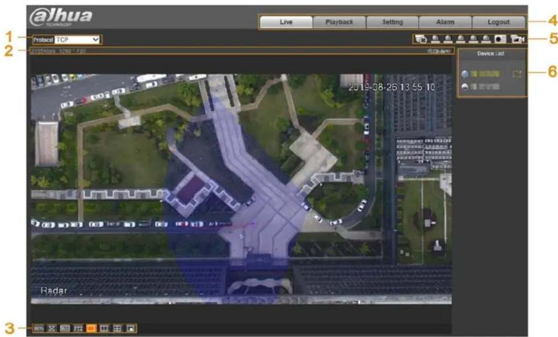
Table 2-1 Live view parameter descriptions
| No. | Description | No. | Name |
| 1 | Set encoding mode. | 2 | Video tool. |
| 3 | Adjust video window. | 4 | Function tabs. |
| 5 | Function options. | 6 | Device list. |
2.1 Encoding Configuration
You can select stream media protocol from TCP, UDP, and RTP multicast. See Figure 2-2.
Figure 2-2 Encoding configuration

2.2 Video Tool
You can view bit rate, and resolution, and take records and snapshots, and so on. See Figure 2-3. For parameter descriptions, see Table 2-2.
Figure 2-3 Video tool

Table 2-2 Video tool parameter descriptions
| No. | Name Description | ||
| 1 | Bit Rate | Display the current video bit rate. | |
| 2 | Resolution | Display the current video resolution. | |
| 3 | Digital Zoom | Click the icon, and then draw a box at any area to zoom in the selected part. Scroll on the selected part to zoom in or zoom out the image; point anywhere, and then scroll to zoom in or zoom out the image. Right-click or click the icon again to restore to the original status. | |
| 4 Snapshot | Click the icon to capture the picture of live image. | Snapshot and record configurations are for the radar only.You can modify the storage path inSetting > Radar Settings > Video > Path. For details, see "4.1.1.4 Storage Path." | |
| 5 Record | Click the icon to take record of the live video. | ||
| 6 | Audio | Click the icon to mute or unmute the video. | |
2.3 Video Window Adjustment
You can set window split mode, play the video in full screen, original size, and adaptive size, and more. For details, see Figure 2-4 and Table 2-3.
Figure 2-4 Video window adjustment
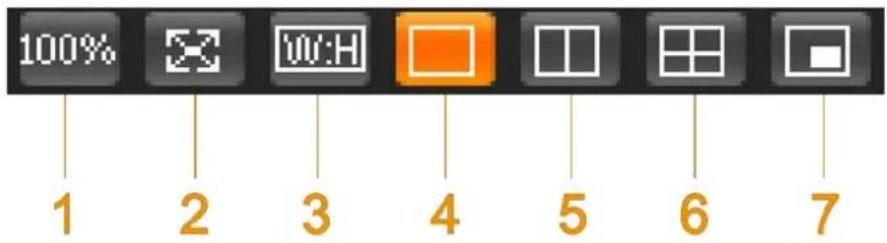
Table 2-3 Icon descriptions
| No. | Name | Description |
| 1 | Image size | Click the icon to display the video in its original size and the icon switches to 100%. Click the icon again, and the video is displayed in adaptive size. |
| 2 | Full screen | Click the icon to play the video in full screen. Double-click or press Esc key to exit full screen. |
| 3 | W:H (Width and height ratio) | Click the icon and then select the ratio as Original or Adaptive. |
| No. | Name Description | |
| 4-6 | Window split | Click the icon to set window split mode.Single live image: [IMAGE]. It is set by default.Double live images:  Four live images: Four live images:  |
| 7 | Picture in picture mode | Click the icon, click the small window at the lower-right corner of the main live image, and then double-click the linked camera from theDevice List.The live view of the selected camera will be displayed in the small window. |
System Menu 2.4
You can click each tab to enter its corresponding interface. See Figure 2-5.
Figure 2-5 System menu

Function Options 2.5
Click each icon to use different functions such as manual positioning, and taking snapshots and records. For details, see Figure 2-6 and Table 2-4.
Figure 2-6 Function options
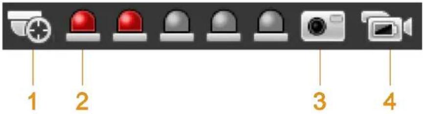
Table 2-4 Function icon descriptions
| No. | Name Description | |
| 1 | Manual Positioning | In 2 or 4 window split mode, click any area on the radar map, and all linked cameras position to that specified area. If you have no operation for more than 30 s after clicking, the camera will restore to default position.To make manual position valid, you need to:Log in to the linked camera.Complete radar positioning and radar calibration. For details, see "4.1.3 Linkage." |
| 2 | Relay-out | Display the alarm output status.An alarm is triggered: The icon turns red.No alarm: The icon is gray.You can click the icon to enable or disable alarm manually. |
| 3 | Snapshot | See Table 2-2. |
| 4 | Record | See Table 2-2. |
Device List 2.6
You can view IP addresses of radar and the linked cameras, and set video stream. See Figure 2-7.
Figure 2-7 Device list
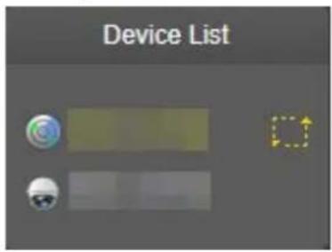
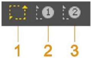
Click to select video streams. For details, see Figure 2-8 and Table 2-5.
Figure 2-8 Select video stream
flowchart
graph TD
    A[" "] --> B["1"]
    A --> C["2"]
    A --> D["3"]
Table 2-5 Video stream icon descriptions
| No. | Name Description | |
| 1 | Main Stream | Under the selected stream media protocol, use main stream to monitor and store video. Main stream is applied in live view and record storage by default. Click the icon again to close live video. |
| 2 | Sub Stream 1 | Under the selected stream media protocol, use sub stream 1 to monitor if the network bandwidth is insufficient. Click the icon again to close live video. |
| 3 | Sub Stream 2 | Under the selected stream media protocol, use sub stream 2 to monitor if the network bandwidth is insufficient. Click the icon again to close live video. |
PTZ Control 2.7
You can control PTZ function of the linked camera by PTZ control bar on Live interface.

- PTZ control is only for radar speed dome tracking system, and you can skip this function as needed.
- Before using PTZ control, you need to add a PTZ camera. For details, see "4.1.2 PTZ Camera."
- PTZ control can only be operated on the selected camera channel.
For PTZ control bar, see Figure 2-9. For detailed icon descriptions, see Table 2-6.
Figure 2-9 PTZ Control
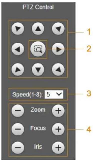
Table 2-6 PTZ control descriptions
| No. Name | Description | |
| 1 | Direction | Support eight directions: Up, down, left, right, upper-left, upper-right, lower-left, and lower-right. |
| 2 | Quick position | Click the icon, draw a box on radar's live interface, and then the PTZ camera will rotate, focus and quickly locate that area. |
| 3 | Speed | PTZ rotation speed. The larger the value is, the higher the speed will be. |
| 4 | Zoom/Focus/Iris | Click [ZBY5] to increase the value and click  to decrease the value.Zoom: Tap to decrease the value.Zoom: Tap  or or  to zoom in or zoom out the image.Focus: Tap to zoom in or zoom out the image.Focus: Tap  or or  to adjust the lens focus to get a desired definition of the video.Iris: Tap to adjust the lens focus to get a desired definition of the video.Iris: Tap  or or  to adjust the brightness of the video. to adjust the brightness of the video. |
3 Playback
You can play back snapshots and videos saved in SD card.

- Snapshot and video playback configurations are only for radar on this web.
- Before playback, you need to configure parameters such as record and snapshot schedule, storage method, and record mode. For details, see "4.4 Storage."
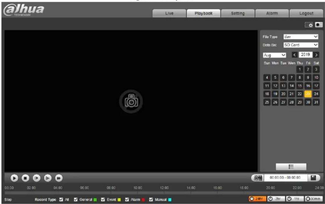
Click Playback tab. The Playback interface is displayed. See Figure 3-1.
Figure 3-1 Playback
Video Playback 3.1
Select file type as dav. The video playback interface is displayed. See Figure 3-2. For details, see Table 3-1.
Figure 3-2 Video playback
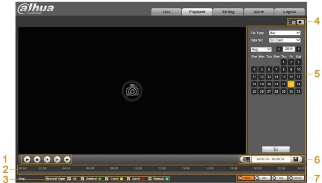
Table 3-1 Video playback function descriptions
| No. | Description |
| 1 | Video playing bar. For details, see "3.1.1 Playing Video." |
| 2 | Time bar. |
| 3 | Record type. For details, see "3.1.2 Record Types." |
| 4 | Auxiliary functions. For details, see "3.1.3 Auxiliary Functions." |
| 5 | Record files. For details, see "3.1.4 Record Files." |
| 6 | Clip. For details, see "3.1.5 Clipping Records." |
| 7 | Time format of the time bar. For details, see "3.1.6 Time Format of the Time Bar." |
3.1.1 Playing Video
You can do video playback operations such as playing and pausing, stopping, fast and slow playing, and playing by frame. For details, see Figure 3-3 and Table 3-2.
Figure 3-3 Video playing bar
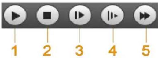
Table 3-2 Video playing bar icon descriptions
| No. | Name Description | |
| 1 | Play and pause | Click the icon to play or pause playing the record. |
| 2 | Stop | Click the icon to stop playing video. |
| 3 | Play by frame | Click the icon to play the record by frame.You need to pause playback when using this function. |
| 4 | Slow play | Click the icon to play slowly. |
| 5 | Fast play | Click the icon to play fast. |
3.1.2 Record Types
Select the record type, and only selected files will be displayed in the time bar and file list. See Figure 3-4.
Figure 3-4 Record type

3.1.3 Auxiliary Functions
You can zoom in or zoom out the image, and take a snapshot. For details, see Figure 3-5 and Table 3-3.
Figure 3-5 Auxiliary functions
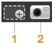
Table 3-3 Auxiliary function icon descriptions
| No. | Name Description | |
| 1 | Digital Zoom | For details, see "2.2 Video Tool." |
| 2 | Snapshot | For details, see "2.2 Video Tool." |
3.1.4 Record Files
Select file type, data source, and date, and then you can play back records. On the calendar, the date with blue background means the current date has records. See Figure 3-6. For parameter descriptions, see Table 3-4.
Figure 3-6 Select records
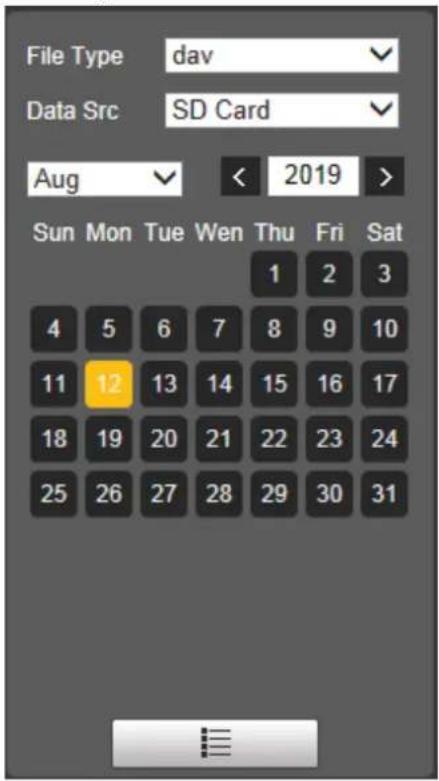
Table 3-4 Record parameter descriptions
| Parameter Description | |
| File Type | Select dav for video playback. |
| Data Src Data source. It is from SD card by default. | |
| File list. Click the icon, and then the video files of the selected date will be displayed in the list. | |
3.1.5 Clipping Records
You can clip the selected record as needed. The function column is displayed as Figure 3-7.
Figure 3-7 Clip record

Step 1 Select start time of clipping on time bar which should be within time range of the record.
Step 2 Move your mouse pointer to and then Select Start Time is displayed.
Step 3 Click to set the start time for video clipping.
Step 4 Select end time of clipping on time bar which should be within time range of the record.
Step 5 Move your mouse pointer to and then Select End Time is displayed.
Step 6 Click to set the end time for video clipping.
Step 7 Click 📄, and the clipped video will be saved in the path of video clips. For details, see "4.1.1.4 Storage Path."
3.1.6 Time Format of the Time Bar
You can set time format of the time bar as 24 h, 2 h, 1 h, and 30 min. For details, see Figure 3-8 and Table 3-5.
Figure 3-8 Time format

Table 3-5 Time format descriptions
| Icon Description | |
| Click the icon to display the time bar in 24-hour mode. | |
| Click the icon to display the time bar in 2-hour mode. | |
| Click the icon to display the time bar in 1-hour mode. | |
| Click the icon to display the time bar in 30-min mode. |
3.2 Snapshot Playback
Select file type as jpg. The snapshot playback interface is displayed. See Figure 3-9. For details, see Table 3-6.
Figure 3-9 Snapshot playback
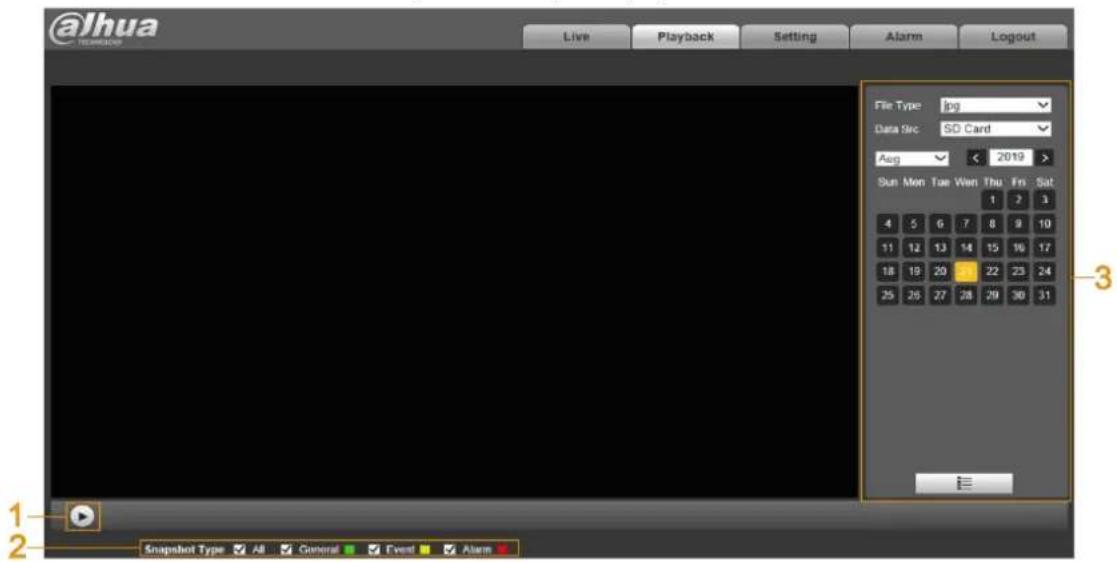
Table 3-6 Picture playback function descriptions
| No. | Description |
| 1 | Picture playing bar. For details, see "3.2.1 Playing Snapshots." |
| 2 | Snapshot type. For details, see "3.2.2 Snapshot Files." |
| 3 | Snapshot file. For details, see "3.2.3 Snapshot Types." |
3.2.1 Playing Snapshots
You can play and pause playing snapshots. See Figure 3-10.
Figure 3-10 Picture playing bar
3.2.2 Snapshot Files
Select file type, data source, and date, and then you can play back snapshots. On the calendar, the date with blue background means the current date has snapshots. See Figure 3-11. For parameter descriptions, see Table 3-7.
Figure 3-11 Select snapshots
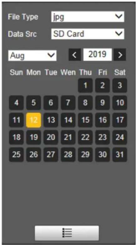
Table 3-7 Snapshot parameter descriptions
| Parameter Description | |
| File Type | Select jpg for picture playback. |
| Data Src Data source. It is from SD card by default. | |
 | File list. Click the icon, and then the snapshot files of the selected date will be displayed in the list. See Figure 3-12. |
Figure 3-12 Device list
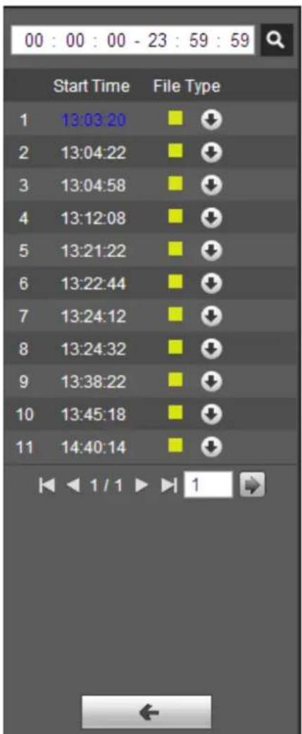
On device list interface, you can double-click the file to play back pictures. For more icon descriptions, see Table 3-8.
Table 3-8 Device list icon descriptions
| Icon Description | |
 | Click the icon to search all snapshot files within the start time and end time of selected date. |
 | Click icon to download snapshot file to local storage. |
 | Click icon to return to calendar interface and re-select time to operate. |
3.2.3 Snapshot Types
Select the record type, and only selected files will be displayed in the time bar and file list. For details, see "3.1.2 Record Types."
4 Setting
This chapter introduces how to configure and view the radar information, including settings about radar, network, event, storage, and system.
Radar 4.1
You can make configurations about radar such as setting video and snapshot parameters, adding PTZ cameras, doing radar and camera linkage, managing protection zone, and setting IVS.
4.1.1 Video
You can set video stream, snapshots, overlay, and storage path.
4.1.1.1 Video Stream
You can set the main stream and sub stream of live videos.
Step 1 Select Setting > Radar Settings > Video > Video.
The Video interface is displayed. See Figure 4-1.
Figure 4-1 Set video stream
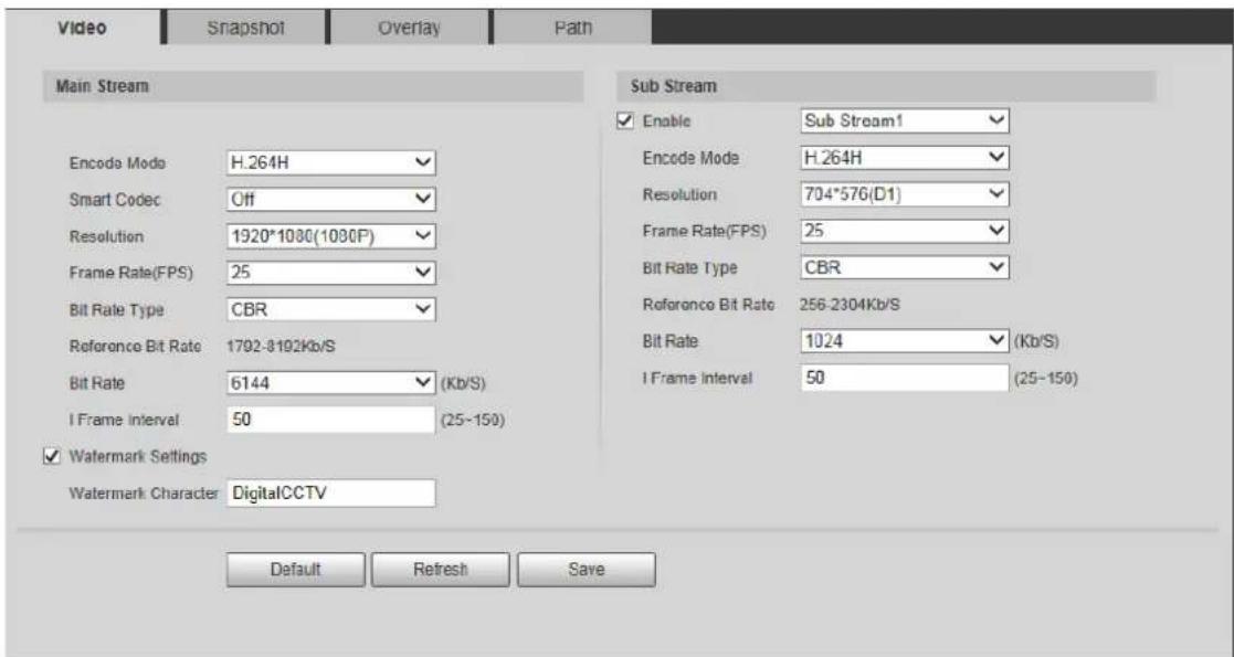

- Video stream configuration interface might vary with different devices, and the actual interface shall prevail.
- Default values might vary with different video streams, and the actual interface shall prevail.
Step 2 Configure parameters as needed. For details, see Table 4-1.
Table 4-1 Video stream parameter descriptions
| Parameter Description | |
| Enable | By selecting Enable check box or not, you can enable or disable the sub stream. It is enabled by default. |
| Encode Mode | Select the encode mode from H.264, H.264H, H.264B, and H.265. |
| Smart Codec | Enable smart codec to improve video compressibility and save storage space. [IMAGE]After smart codec is enabled, the third bit stream, ROI, and smart event detection will be disabled. The actual interface shall prevail. |
| Resolution | Select the resolution of main stream and sub stream. Each resolution has different reference bit rate. |
| Frame Rate (FPS) | PAL: 1–25 frame per second. Frame rate varies with different resolutions. |
| Bit Rate Type | Include CBR and VBR. You can set Quality (from 1 to 6, and 6 is the best) under VBR mode. |
| Reference Bit Rate | The most suitable bit rate range recommended to users according to the set resolution and frame rate. |
| Bit Rate | The value is the upper limit of the stream in VBR mode. In CBR mode, it is fixed. Refer to Reference Bit Rate to acquire the best setting rage. |
| I Frame Interval | The number of P frame between two I frames. The range varies with the bit rate and is up to 150. It is recommended to set the number as twice of the bit rate. |
| Watermark Settings | You can verify the watermark to check if the video has been tampered. Select Watermark Settings check box to enable watermark. |
| Watermark Character | The watermark character is DigitalCCTV by default. [IMAGE]The watermark characters (Max. 128 characters) can be Chinese characters, letters, symbols, punctuation marks, space or special characters. |
Step 3 Click Save.
4.1.1.2 Snapshot
You can configure snapshots captured from monitoring video.
Step 1 Select Setting > Radar Settings > Video > Snapshot.
The Snapshot interface is displayed. See Figure 4-2.
Figure 4-2 Set snapshot
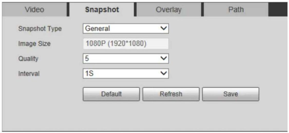
Step 2 Configure parameters as needed. For details, see Table 4-2.
Table 4-2 Snapshot parameter descriptions
| Parameter Description | |
| Snapshot Type | General: The system takes snapshots as scheduled. For details of schedule setting, see "4.4.1 Schedule."Event: The system takes snapshots when the external alarm is triggered. For detailed configuration, see "4.3 Event Management." |
| Image Size | It is the same as the resolution of snapshot under main stream by default. |
| Quality | Set the image quality. There are six levels from 1 to 6. 6 is the best. The higher the level is, the larger the picture will be. |
| Interval | Set snapshot taking frequency. The value ranges from 1 s to 7 s or can be customized. |
Step 3 Click Save.
4.1.1.3 Overlay
You can overlay information such as channel title, time title and more on videos.
Step 1 Select Setting > Radar Settings > Video > Overlay.
The Overlay interface is displayed.
Step 2 Configure the overlay information as needed. See Figure 4-3, Figure 4-4, Figure 4-5, Figure 4-6, Figure 4-7, and Figure 4-8. For parameter descriptions, see Table 4-3.
Figure 4-3 Channel title
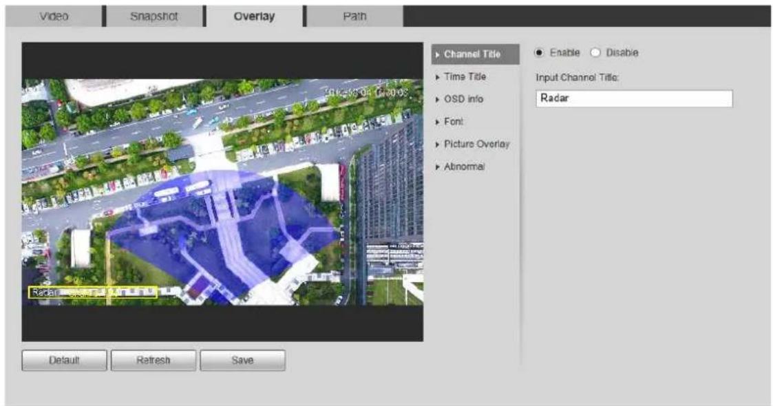
Figure 4-4 Time title
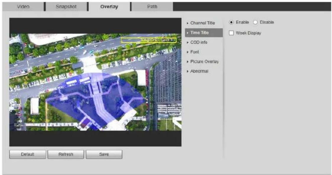
Figure 4-5 OSD information
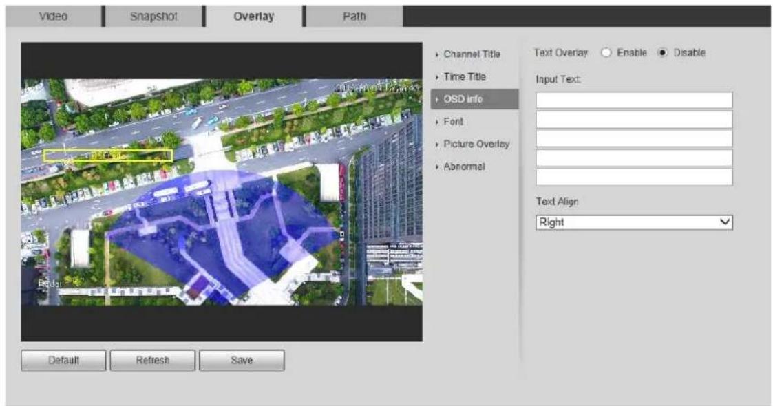
Figure 4-6 Font
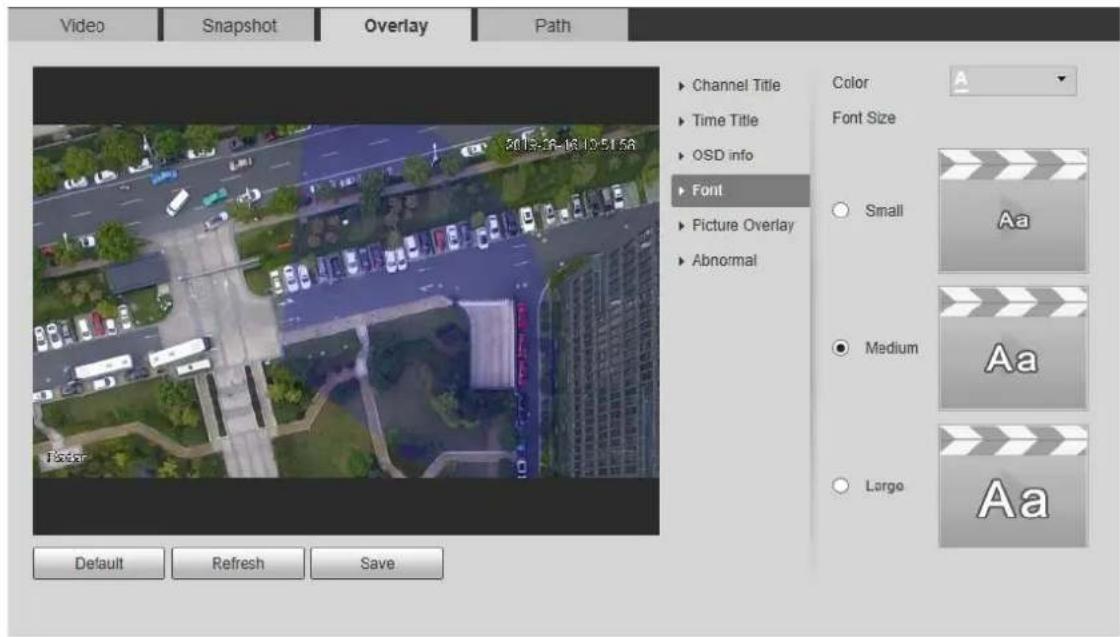
Figure 4-7 Picture overlay
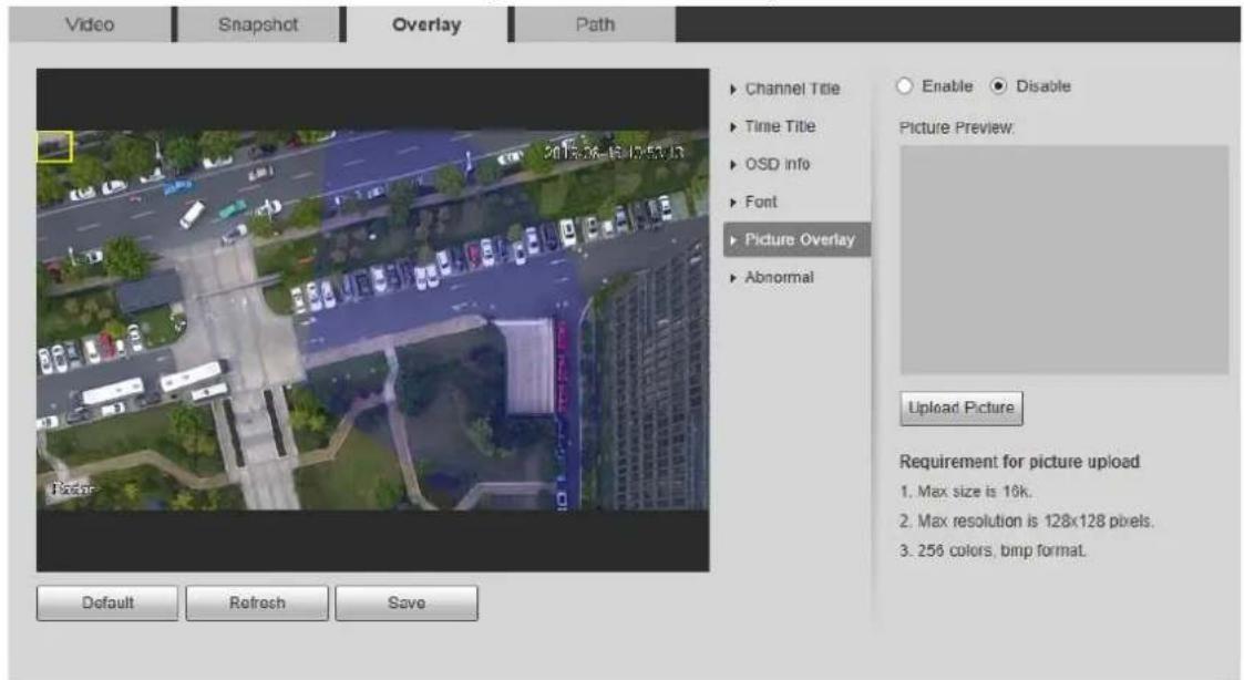
Figure 4-8 Abnormal
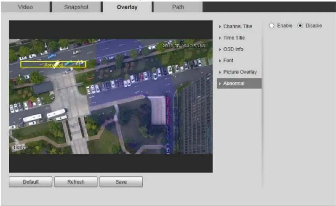
Table 4-3 Overlay configuration parameter descriptions
| Name Description | |
| Channel Title | Enable or disable Channel Title to be overlaid on the video image. Drag the Channel Title box to adjust the display position. |
| Time Title | Enable or disable Time Title to be overlaid on the video image. By selecting Week Display check box, the day will be displayed. Drag the Time Title box to adjust the display position. |
| OSD Info | Enable or disable geographical position to be overlaid on the video image. Drag the OSD info box to adjust the display position. The text can be left-aligned or right-aligned. |
| Font | Set the font colour and font size of channel title, time title, and OSD information. |
| Picture Overlay | Enable or disable picture to be overlaid on the video image. ClickUploadPictureto overlay the local picture on the video image. Drag the yellow box to adjust the picture display position. |
| OSD info and picture overlay cannot be disabled at the same time. | |
| Abnormal | Enable or disable abnormal information to be overlaid on the video image. |
Step 3 Click Save.
You can set storage paths of snapshots and records taken from live view, and snapshots, downloads and video clips from playback.
Step 1 Select Setting > Radar Settings > Video > Path. The Path interface is displayed. See Figure 4-9.
Figure 4-9 Path
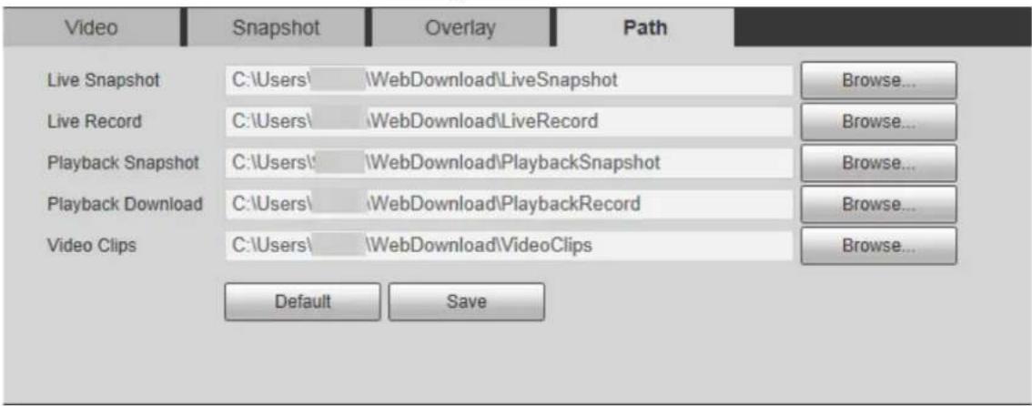
Step 2 Click Browse... to change the default storage path.
Step 3 Click Save.
4.1.2 PTZ Camera
You can add or delete PTZ cameras, set camera name and type, and enable or disable alarm track.

PTZ camera configuration is only for radar speed dome tracking system, and you can skip this setting as needed.
Step 1 Select Setting > Radar Settings > PTZ Camera.
Figure 4-10 Add PTZ camera
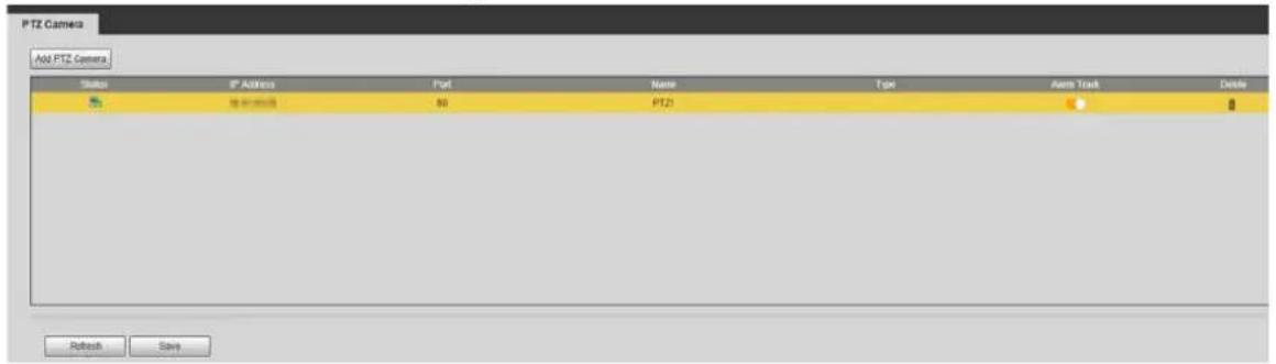
Step 2 Click Add PTZ Camera.
Figure 4-11 Add PTZ camera
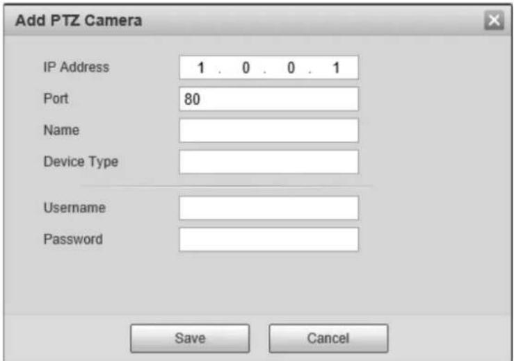
Step 3 Enter IP address, port, camera name, type, username, and password.

Port is set to 80 by default. Keep the port consistent with the PTZ camera.
Step 4 Click Save.

Switch to to enable alarm track linkage between the radar and the selected camera.
4.1.3 Linkage
You can import a map, and set linkage between the radar and the added cameras after finishing radar positioning and calibration.
Importing a Map
Step 1 Select Setting > Radar Settings > Linkage.
Figure 4-12 Linkage
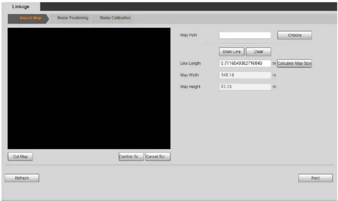
Step 2 Click Choose to import a map.

.png, .jpg, and .bmp format are supported.
Figure 4-13 Import a map
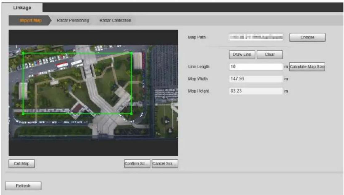
Step 3 Crop the map according to the detection range of the radar. Drag the box to select the range, and then click Cut Map.
Step 4 Click Confirm Screen to get the map with the range you need.

Click Cancel Screenshot to cancel the cropping.
Calculate the map size. Step 5
1) Measure a distance in the actual detection area.
2) On the web client, click Draw Line to draw the measured distance on the image.
3) Click and hold the left mouse button to start drawing, and then release the button to complete drawing.

- Double-click the map to enter full screen display to draw the line more accurately.
- Click Clear to clear the line you drew.
4) Enter the actual measured length of the line you drew in the Line Length input box and then click Calculate Map Size.
The system will automatically get the map width and height.
5) Click Next.
Radar Positioning
Step 1 Drag the end points of the yellow sector on the map to adjust the radar orientation.

- When the dotted line points to the right horizontally, it is considered as 0°. The degree increases clockwise, and you can also adjust degree value by clicking /— or entering a number.
- Double-click the map to enter full screen to position the radar more accurately.
Figure 4-14 Radar positioning
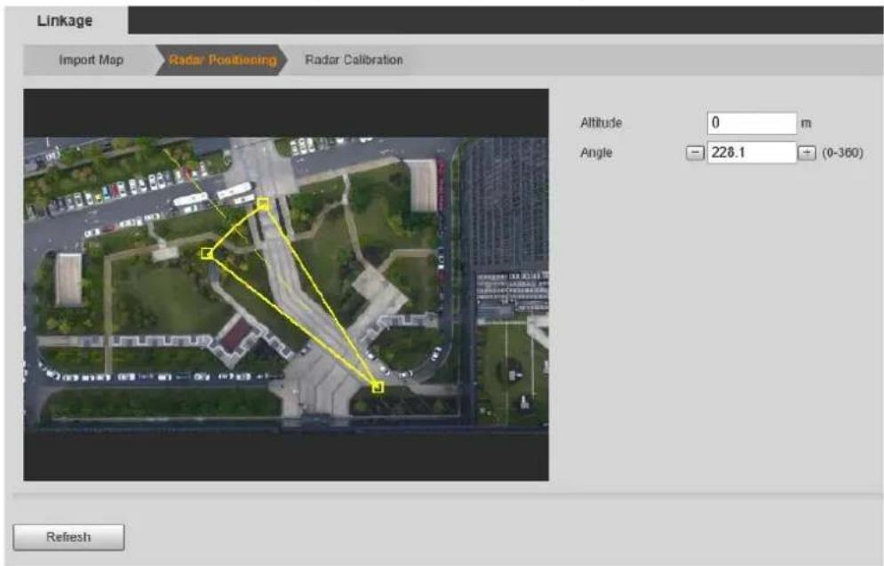
Step 2 Enter installation height of the radar in Altitude box.

Enter height of the radar center (front side); otherwise the camera-radar linkage effect will be reduced.
Step 3 Click Next.
(Optional) Radar Calibration

Radar calibration is only for Radar-PTZ Linkage, and you can skip this setting as needed.
Step 1 Select a PTZ camera in PTZ Camera List, and then enter the username and password used to log in to the web interface of the camera.

- You must log in to the PTZ camera before calibration. For details, see "4.1.2 PTZ Camera".
- If you need to link multiple cameras, click PTZ Camera List at the upper-left corner above the live image to switch to another camera, and then repeat the following steps.
Figure 4-15 Log in to the camera
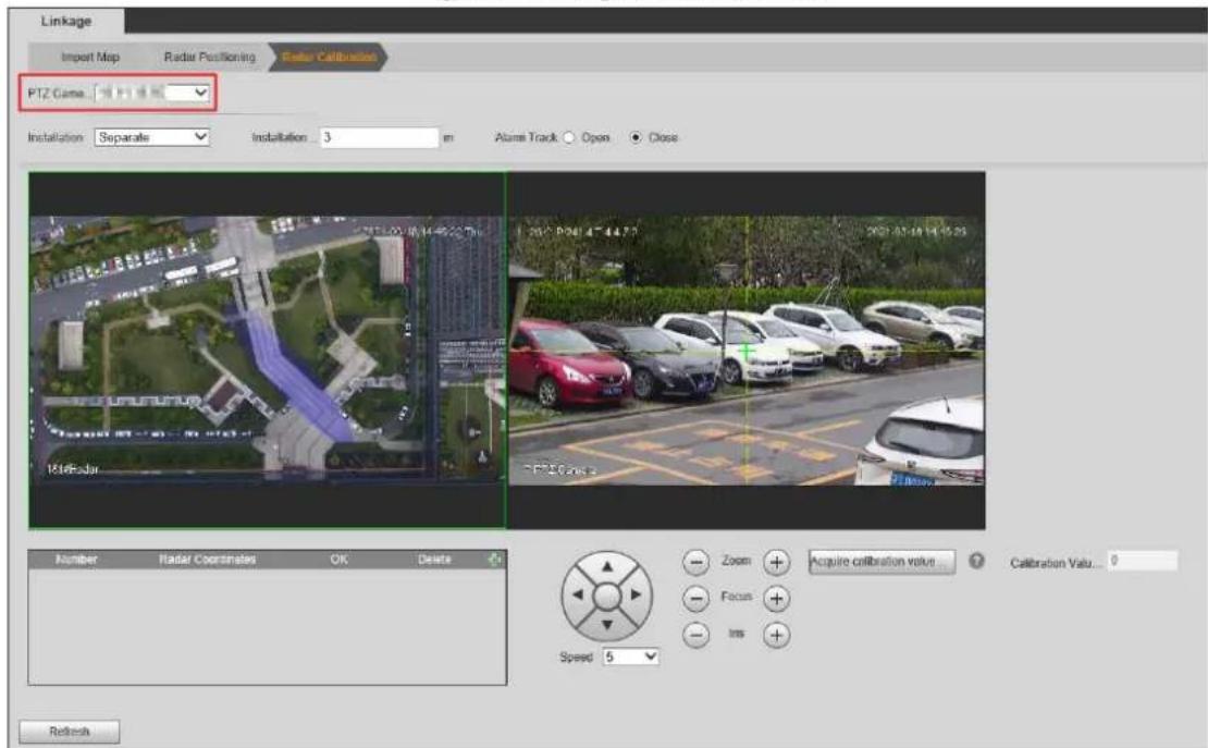
Step 2 Enter the installation height of the camera.

Enter the height of the lens; otherwise the camera-radar linkage effect will be reduced.
Step 3 Select Close to turn off Alarm Track; otherwise you cannot calibrate the camera.
Step 4 Select installation methods from Separate and Integrated.
- Separate: Radar and the camera are installed at different height in a same pole.
- Integrated: Radar and the camera are integrally installed in a same pole.
Step 5 Add radar coordinates to calibrate radar.

- Set coordinates 10 m–20 m away from the PTZ camera and make sure they are within the radar detection range.
- Two people are required: Person A is on the site, and Person B doing configurations on the Web. Keep A and B stay in contact.
1) Double-click the map to enter full screen, and then click + to add radar coordinates.
2) A walks until a green track appears. After A stops, the track of A will disappear and turn into an orange static track point.
3) Aim to the feet of A and adjust the PTZ camera image to make sure the target takes up 1/2 of the image.
4) Click 📄 to save the settings.

For separate installation, repeat the above steps to add the second set of radar coordinate. PTZ camera and the two sets of coordinates must not on the same straight line.
5) Select a target point (More than 10 m away from the camera is recommended) with the same height as the lens. Adjust monitoring image of the camera by using PTZ control icons to move the crosshair to the target point, and then click Acquire calibration value.
6) Enable Alarm Track on the interface, and then click Save.
4.1.4 Region Management
You can add different types of regions, draw alarm, pre-warning, or shield areas, set arming periods, filter objects in regions, and more.
Step 1 Select Setting > Radar Settings > Region.
Figure 4-16 Region
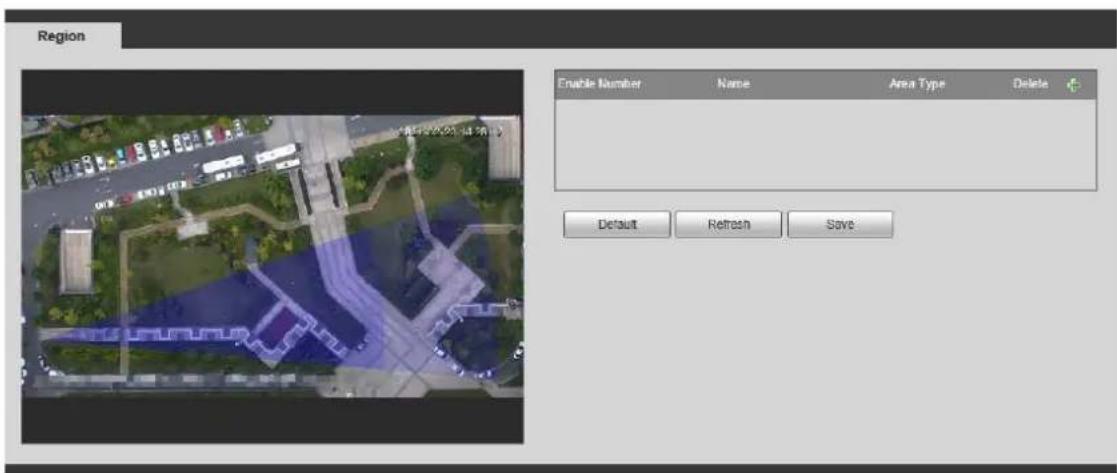
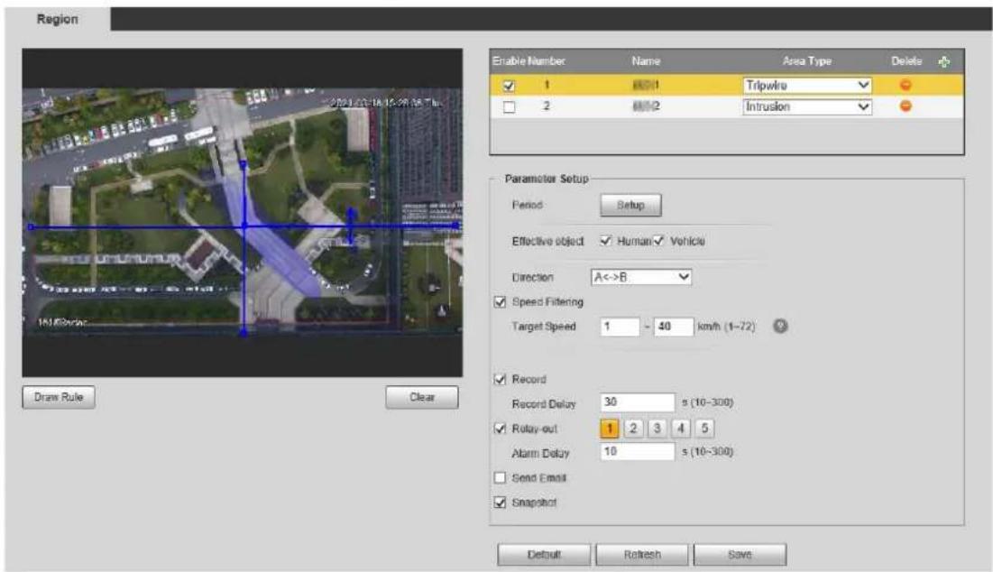
Step 2 Click + to add regions. Regions are enabled by default.
Step 3 Double-click the name under the Name column to modify the region name.
Step 4 Select Area Type from Intrusion and Tripwire.
- Intrusion: When the target enters, leaves, or appears in the detection area, the system performs alarm linkages.
- Tripwire: When the target crosses tripwire from the defined motion direction, the system performs alarm linkages.
Step 5 Click Draw Rule to draw a line or an area within radar detection range.
Click the left mouse button to start drawing, and then click the right mouse button to end drawing.

The area you draw can exceed the edges of the detection region.
Figure 4-17 Draw an area
Step 6 Click Setup to configure arming periods.
Figure 4-18 Set arming periods
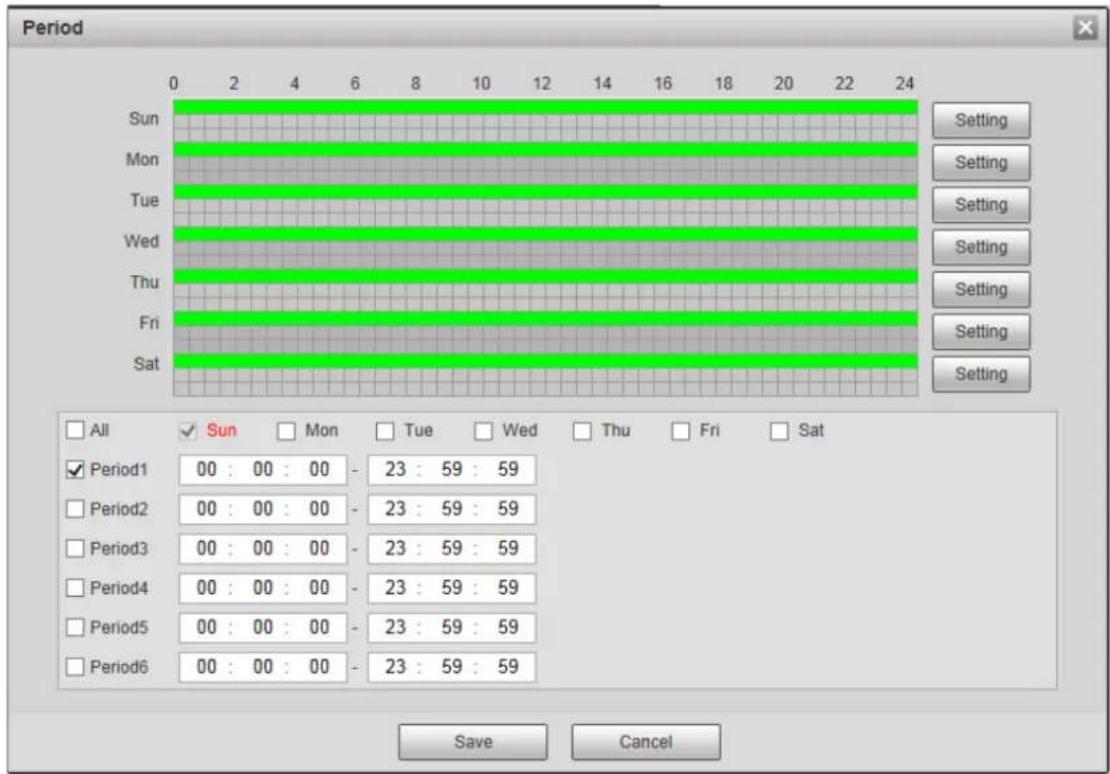
1) Set arming periods, and the alarm can only be triggered when it occurs during the defined period. The time period in green on the timeline is armed.
◇ Method one: Click Setting of the day you want to set. Directly press and drag the left mouse button on the timeline.
◇ Method two: Click Setting of the day you want to set. Select the check box in front of the time period to enable it. Enter start time and end time of that time period.

- Select All or the check box of any other day, and the set time period will apply to the selected days.
• You can set 6 time periods per day.
2) Click Save.
Step 7 Configure other parameters as needed. For details, see Table 4-4. For alarm rules of different regions, see Table 4-5.
Table 4-4 Region management parameter descriptions
| Name Description | |
| Effective Object | Select monitoring target to be monitored from Human and Vehicle. |
| Direction | Set the alarm direction for tripwire. A->B, B->A, and A<->B are available. |
| Alarm Type | Set alarm type for intrusion. Alarm, pre-warning, and shield are available.Priority: Shield > Alarm > Pre-warning. See "Table 4-5 Region alarm rule descriptions" for details. |
| Speed Filtering | Objects whose speeds are not within the specified target speed range will not trigger alarms.[IMAGE]For 50 m and 120 m radars with the model of PFRK series, the speed range must be within 1 to 40 km/h, and for radars with the model of PFRQ series, the speed range must be within 1 to 108 km/h.For 240 m radar, the speed range must be within 1 to 72 km/.For 300 m and 450 m radars, the speed range must be within 1 to 80 km/h. |
| Record | By selecting Record, the system will record automatically when the alarm is triggered.[IMAGE]Before enabling this function, you need to configure record period in Setting > Storage > Schedule > Record. For details, see "4.4.1.1 Record Schedule." In Setting > Storage > Record Control, select Auto for the Record Mode.When the alarm track is enabled, the radar will control the camera to record, and the record rules of the camera are invalid. When the alarm track is disabled, the radar will not control the camera, and the camera will record under its own recording rules. |
| Record Delay | The alarm record keeps running for the defined time (from 10 s to 300 s) after the alarm is ended. |
| Relay-out | By selecting Relay-out, the corresponding alarm output device will be linked through alarm output port when the alarm is triggered. Five alarm output ports. Only 50 m/120 m radar supports high power device control. No.5 is connected to the high power device. |
| Alarm Delay | The alarm keeps running for the defined time (from 10 s to 300 s) after the alarm is ended. |
| Send Email | By selecting Send Email, the system automatically sends email to the specified mailbox when the alarm is triggered. You can configure the mailbox in Setting > Network > SMTP (Email). For details, see "4.2.5 SMTP (Email)." |
| Snapshot | By selecting Snapshot, the system automatically captures images when the alarm is triggered. You can configure the snapshot taking period in Setting > Storage > Schedule > Snapshot. For details, see "4.4.1.2 Snapshot Schedule." |
Table 4-5 Region alarm rule descriptions
| Region Description | |
| Alarm area | Secondary priority. The target will be tracked when it enters the alarm area.When targets appear both in the alarm area and pre-warning area, only the target in alarm area will be tracked. |
| Pre-warning area | Lowest priority. The target will be tracked when it enters the pre-warning area. |
| Shield area | Highest priority. The target will not be tracked, and its track will not be displayed in the shield area.When objects that might cause misinformation such as trees occur in shield area and alarm area at the same time, the alarm will not be triggered. |
Step 8 Click Save.
4.1.5 Protection Zone Management
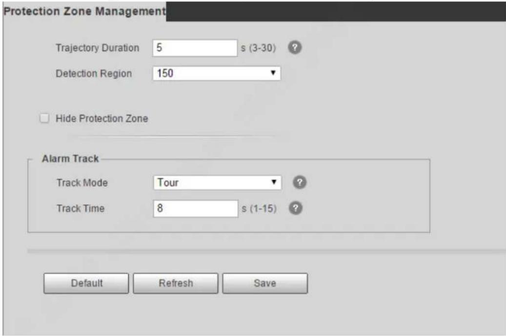
You can set trajectory duration, select channels for radar, configure alarm track, and more.
Step 1 Select Setting > Radar Settings > Protection Zone Management.
Figure 4-19 50 m/120 m (PFRK series) protection zone management
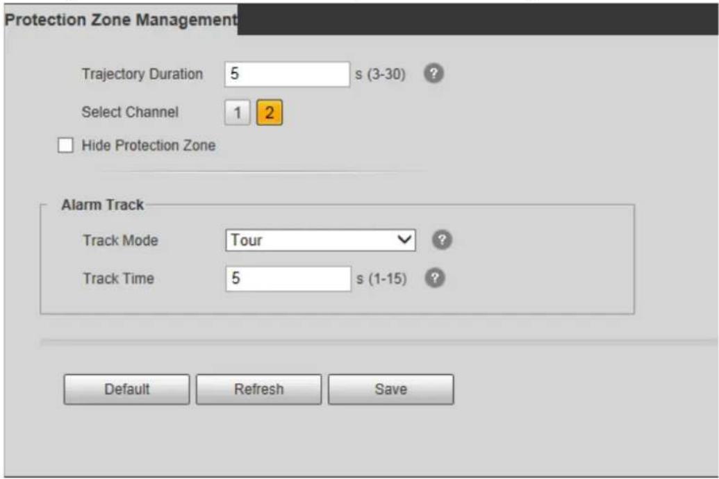
Figure 4-20 240 m protection zone management
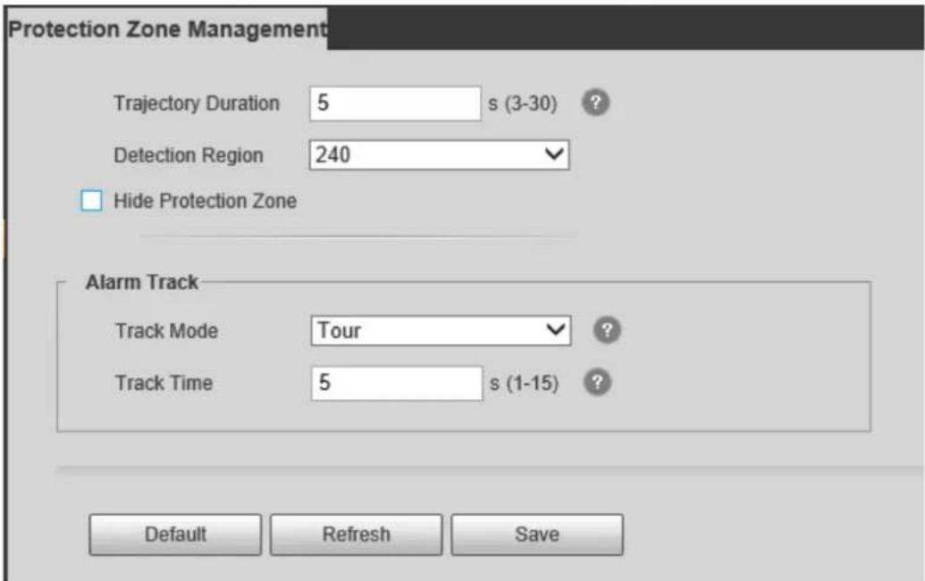
Figure 4-21 300 m/450 m protection zone management
Step 2 Configure parameters as needed.
Table 4-6 Parameter descriptions of protection zone management
| Name Description | |
| Trajectory Duration | Trajectory duration of targets, ranging from 3 s to 30 s. |
| Select Channel | You can select different channels for radar to avoid co-channel interference. Applicable to 50 m/120 m radar.Co-channel interference: In radar's protection zone, interference signals from other devices in the same frequency band will cause the radar to give cluttering trajectory and misinformation more frequently. Applicable to 50 m/120 m radar.Co-channel interference: In radar's protection zone, interference signals from other devices in the same frequency band will cause the radar to give cluttering trajectory and misinformation more frequently. |
| Detection Region | Select the detection region according to actual application.For 240 m radar, 100/240 m available (240 m by default).For 300 m radar, 150/300 m available (300 m by default).For 450 m radar, 300/450 m available. Applicable to 240 m/300 m/450 m radar.The device will restart if the value is changed. Applicable to 240 m/300 m/450 m radar.The device will restart if the value is changed. |
| Hide Protection Zone | Select the check box to hide protection area. |
| Track Mode | Tour: The camera tracks all targets in the detection region in turn.Distance Priority: The camera tracks the target nearest to the radar in the detection region.Time Priority: The camera tracks the target appearing earliest in the detection region. |
| Track Time | The maximum tracking time of each target, ranging from 1 s to 15 s.[IMAGE]Track time is only for Tour track mode. |
Step 3 Click Save.
4.1.6 IVS Setup
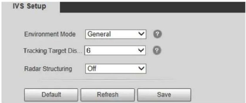
You can select environment mode, set displaying scale of the tracked target, and radar structuring.
Step 1 Select Setting > Radar Settings > IVS Setup.
Figure 4-22 IVS setup
Step 2 Configure parameters as needed. For details, see Table 4-7.
Table 4-7 IVS setup parameter descriptions
| Name Description | |
| Environment Mode | General: Apply to detection regions without shrubs, except large barriers such as cars.Shrub: Apply to detection regions with trees, shrubs, and other swaying objects that might cause misinformation.Capacious: Apply to detection regions without trees, shrubs, or large barriers.240 m/300 m/450 m radar do not support environment mode. |
| Tracking Target Display | Display the tracking target by setting a specific value from 1 to 6. The bigger the value is, the larger the target is in the linkage image. |
| Radar Structuring | By enabling Radar Structuring, the tracking distance, angle, moving speed, and type of the tracked target will be displayed on live view interface. |
4.2 Network
This chapter introduces network configuration.
4.2.1 TCP/IP
You can configure IP address, DNS (Domain Name System) server of the radar to make sure that it can be mutually connected to other devices in the networking.

- Confirm the radar has connected to network correctly before setting network parameters.
- Allocate IP address of the same network segment if there is no router in the network.
- Set corresponding gateway and subnet mask if there is a router in the network.
Step 1 Select Setting > Network > TCP/IP.
The TCP/IP interface is displayed. See Figure 4-23.
Figure 4-23 TCP/IP
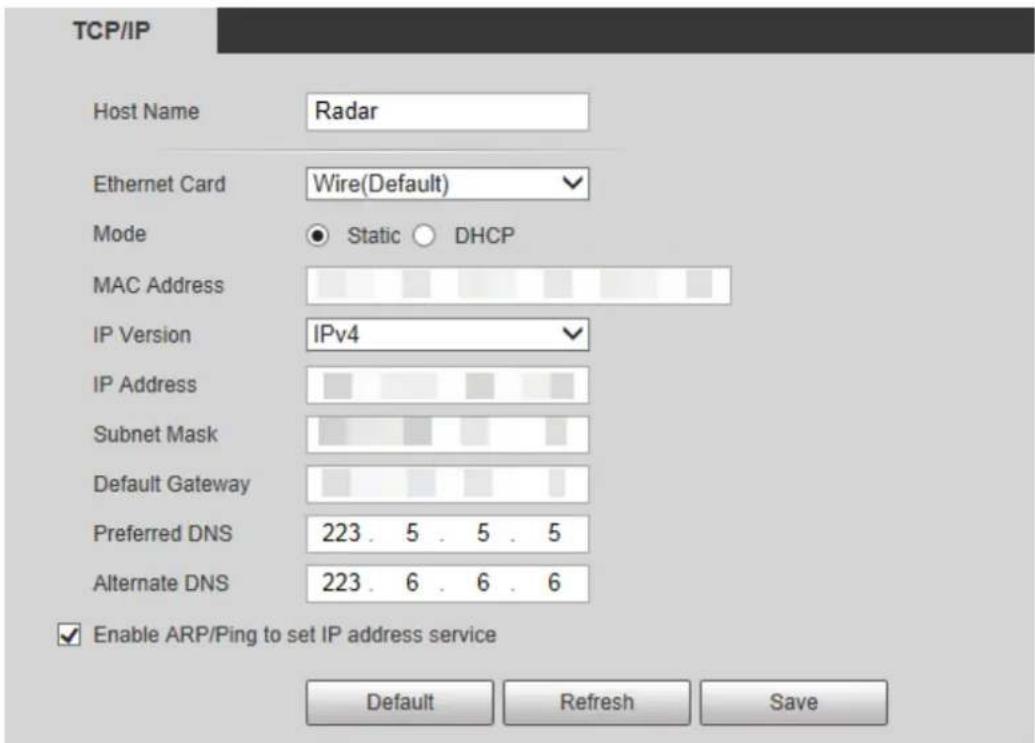
Step 2 Configure parameters. See Table 4-8.
Table 4-8 TCP/IP parameter descriptions
| Parameter Description | |
| Host Name | Enter host name, 15 characters at most. |
| Ethernet Card | Select the Ethernet card that needs to be configured. The default one isWire.You can change the default Ethernet card if there is more than one card.Restart radar to activate the new settings once you modify the default settings. |
| Mode | DHCP: The system acquires IP address automatically. You cannot set the IP address, subnet mask and default gateway.Static: You need to configure IP address, subnet mask and default gateway manually. |
| MAC Address | Display the MAC address of radar. |
| IP Version | Select IP version from IPV4and IPV6and both versions can be accessed. |
| IP Address | Enter the IP address, subnet mask, and default gateway as needed when |
| Subnet Mask | selecting Static mode. |
| Default Gateway | • IPV6 has no subnet mask.• The default gateway must be in the same network segment with the IP address. |
| Preferred DNS | IP address of the preferred DNS. |
| Alternate DNS | IP address of the Alternate DNS. |
| Enable ARP/Ping to set IP address service. | Select the check box, get the device MAC address, and then you can modify and configure the device IP address with ARP/ping command.It is enabled by default. During restarting, you will have no more than 2 minutes to configure the device IP address by a ping packet with defined length, the server will be turned off in 2 minutes, or it will be turned off immediately after the IP address is successfully configured. If the service is not enabled, the IP address cannot be configured with ping packet. |
Step 3 Click Save.
A demonstration of configuring IP address with ARP/Ping
Step 1 Keep the device that needs to be configured and the PC within the same LAN, and then get an IP address available.
Step 2 Get the physical address of the radar from its label.
Step 3 Open command editor on the PC and enter the following command. See Table 4-9.
Table 4-9 Command list
| Parameter Description | |
| Windows syntax | Arp -s <IP Address> <MAC>Ping -l 480 -t <IP Address>Example:Arp -s 192.168.0.125 11-40-8c-18-10-11Ping -l 480 -t 192.168.0.125 |
| UNIX/Linux/Mac syntax | Arp -s <IP Address> <MAC>Ping -s 480 <IP Address>Example:Arp -s 192.168.0.125 11-40-8c-18-10-11Ping -s 480 192.168.0.125 |
| Win7 syntax | netsh i i show innetsh -c "ii" add neighbors ldx <IP Address> <MAC>ping -l 480 -t <IP Address>Example:netsh i i show innetsh -c "i i" add neighbors 12 192.168.0.12511-40-8c-18-10-11ping -l 480 -t 192.168.0.125 |
Step 4 Power off and restart radar or restart the device by network.
Step 5 Check the PC command line. If information such as "Reply from 192.168.0.125..." is displayed, the configuration has succeeded, and then you can close the command line.
Step 6 Enter http://(IP address) in the browser address bar to log in.
4.2.2 Port
This section introduces configurations of the maximum number of users that can connect to the radar simultaneously and value of each port.
Step 1 Select Setting > Network > Port.
The Port interface is displayed. See Figure 4-24.
Figure 4-24 Port
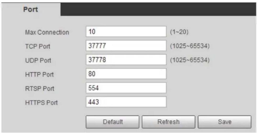
Step 2 Configure port parameters. See Table 4-10.

- The configuration of Max Connection takes effect immediately and others after the radar is restarted.
- 0–1024, 1900, 3800, 5000, 5050, 9999, 37776, 37780–37880, 39999, 42323 are occupied for specific uses.
- It is not recommended to use the default value of other ports during port configuration.
Table 4-10 Port parameter description
| Parameter Description | |
| Max Connection | The maximum number of users that can log in to the web interface simultaneously of the same radar. The value ranges from 1 to 20 and 10 is set by default. |
| TCP Port | Transmission control protocol port, the default value is 37777, and it can be modified as needed. |
| UDP Port | User datagram protocol port, the default value is 37778, and it can be modified as needed. |
| HTTP Port | Hypertext transfer protocol port, the default value is 80, and it can be modified as needed. |
| RTSP Port | Real time streaming protocol port, leave it if the value is 554 by default. If you play live view with QuickTime, VLC or Blackberry smart phone, the following URL format is available.When the URL format requiring RTSP, you need to specify channel number and bit stream type in the URL, and also username and password if needed.When playing live view with Blackberry smart phone, you need to turn off the audio, and then set the codec mode to H.264B and resolution to CIF.URL format example:rtsp://username:password@ip:port/cam/realmonitor?channel=1&subtype=0Among that:Username: Your username, such as admin.Password: Your password, such as admin.IP: Your device IP, such as 192.168.1.122.Port: Leave it if the value is 554 by default.Channel: Channel number, which starts from 1. For example, if you are using channel 2, then the channel=2.Subtype: Bit stream type; 0 means main stream (subtype=0) and 1 means sub stream (subtype=1).So, if you require the sub stream of channel 2 from a certain device, then the URL should be:rtsp://admin:admin@10.12.4.84:554/cam/realmonitor?channel=2&subtype=1If user name and password are not needed, then the URL can be:rtsp://ip:port/cam/realmonitor?channel=1&subtype=0 |
| HTTPS Port | HTTPS communication port, the default value is 443, and it can be modified as needed. |
Step 3 Click Save.
4.2.3 PPPoE
Point-to-Point Protocol over Ethernet, it is one of the protocols that device uses to connect to the Internet. Get the PPPoE username and password from the Internet service provider, set network connection through PPPoE, and then the device will acquire a WAN dynamic IP address.
Step 1 Select Setting > Network > PPPoE.
The PPPoE interface is displayed. See Figure 4-25.
Figure 4-25 PPPoE
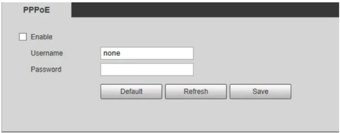
Step 2 Select Enable, and then enter username and password.
Step 3 Click Save.
4.2.4 DDNS
Properly configure DDNS, and then the domain name on the DNS server matches your IP address and the matching relation refreshes in real time. You can always visit your device with the same domain name no matter how much your device IP address changes.
Before making configurations, please check if your radar supports the DNS server.

- Third party server might collect your device information if DDNS is enabled.
- Register and log in to the DDNS website, and then you can view the information of all the connected devices in your account.
Step 1 Select Setting > Network > DDNS.
The DDNS interface is displayed. See Figure 4-26.
Figure 4-26 DDNS (1)
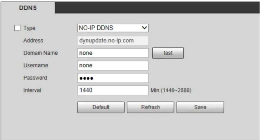
Step 2 Select DDNS Type, and then configure the parameters as needed. See Table 4-11.
Table 4-11 DDNS parameter descriptions
| Parameter Description | |
| Type | The name and web address of the DDNS service provider, see the matching relationship below:CN99 DDNSweb address: www.3322.orgNO-IP DDNSweb address: dynupdate.no-ip.comDyndns DDNSweb address: members.dyndns.org |
| Address | |
| Domain Name | The domain name you registered on the DDNS website. |
| Username | Enter the username and password you got from the DDNS service provide. You need to register an account (with username and password) on the DDNS service provider's website. |
| Password | |
| Interval | The update cycle of the connection between the radar and the server, and the time is 10 min by default. |
Step 3 Click Save.
Open the browser on PC, enter the domain name at the address bar, and then press Enter, the log in interface is displayed.
4.2.5 SMTP (Email)
Configure email parameter and enable email linkage. The system sends email to the server of the receiver through SMPT server when alarm or abnormality is triggered. The receiver can receive the email after logging in to the server.
Step 1 Select Setting > Network > SMTP (Email).
The SMTP (Email) interface is displayed. See Figure 4-27.
Figure 4-27 SMTP (Email)
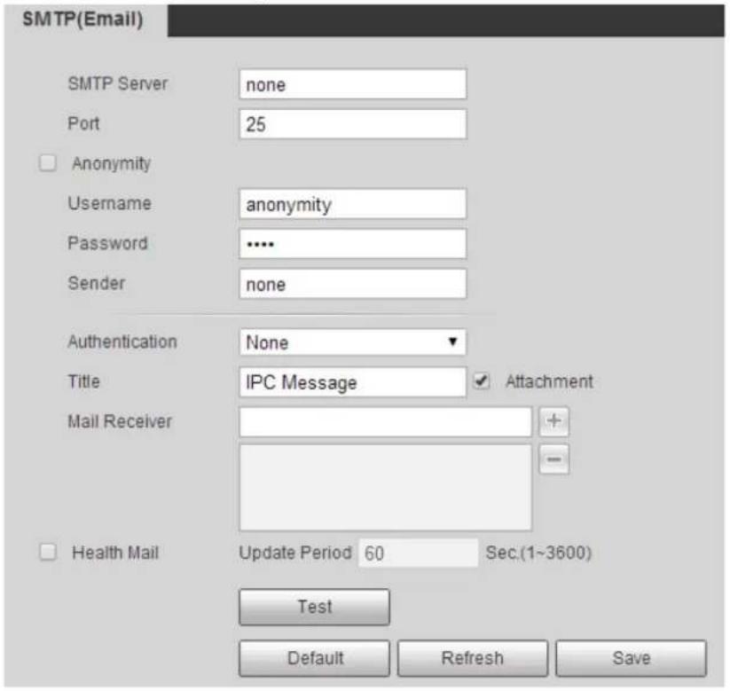
Step 2 Configure parameters. See Table 4-12.
Table 4-12 SMTP (Email) parameter descriptions
| Parameter Description | ||
| SMTP Server | IP address of SMTP server that sends emails. | For the detailed configuration, see Table 4-13. |
| Port | Port number of the SMTP server that sends emails. The default value is 25. | |
| Username | Sender's email username. | |
| Password | Sender's email password. | |
| Anonymity | By enabling this function, the sender's information is not displayed in the email. You can auto log in anonymously, and do not need to enter the username, password and the sender information. | |
| Sender | Sender's email address. | |
| Authentication | Select Authentication from None, SSL and TLS. TLS is set by default.For the detailed configuration, see Table 4-13. | |
| Title | Enter no more than 60 characters in Chinese, English, and Arabic numerals. | |
| Attachment | Select the check box to support attachment in the email. | |
| Mail Receiver | Receiver's email address. Support 3 addresses at most. | |
| Health Mail | The system sends test mails to check if the connection is successfully configured. Select Health Mail, configure the Update Period, and then the system sends test mails as the defined period. | |
| Test | Test the email sending and receiving function. If the configuration is correct, you will receive test mail. Save email configuration before running the test. | |
For the configuration of major mailboxes, see Table 4-13.
Table 4-13 Major mailbox configuration
| Mailbox | SMTP Server | Authentication | Port | Description |
| QQ smtp.qq.com | SSL 465 | The authentication type cannot be None.You need to enable SMTP service in your mailbox.The authentication code is required as password; either the QQ password or email password is not applicable. Authentication code, the code you receive when enabling SMTP service. | ||
| TLS 587 | ||||
| 163 smtp.163.com | SSL | 465/994 | You need to enable SMTP service in your mailbox.The authentication code is required as password; the email password is not applicable. Authentication code, the code you receive when enabling SMTP service. | |
| TLS 25 | ||||
| none | 25 | |||
| Sina | smtp.sina.com | SSL 465 | You need to enable SMTP service in your mailbox. | |
| none | 25 | |||
| 126 | smtp.126.com | none | 25 | You need to enable SMTP service in your mailbox. |
Step 3 Click Save.
4.2.6 UPnP
Universal Plug and Play, a protocol that establishes mapping relation between intranet and Internet. This function enables you to access intranet device through Internet. Internal port is radar's port and external port is router's port. You can access the radar with external port. When UPnP is not needed, you need to disable UPnP function so that other functions can be used normally.
Enable UPnP if radar supports UPnP protocol. In Windows XP or Windows Vista system, if UPnP is enabled, the device can automatically find it in the Network Neighborhood of Windows.
Refer to the following steps to install UPnP network service in the Windows system.
Step 1 Open control panel, and select Add or Remove Programs.
Step 2 Click Add/Remove Windows Components.
Step 3 Select the Network Services in the Windows Components Wizard, and then click Details.
Step 4 Select Internet gateway device discovery and control client, and UPnP user interface, and then click OK to begin installation.
For UPnP configuration on radar web interface, see following steps.
Step 1 Select Setting > Network > UPnP.
The UPnP interface is displayed. See Figure 4-28.
Figure 4-28 UPnP
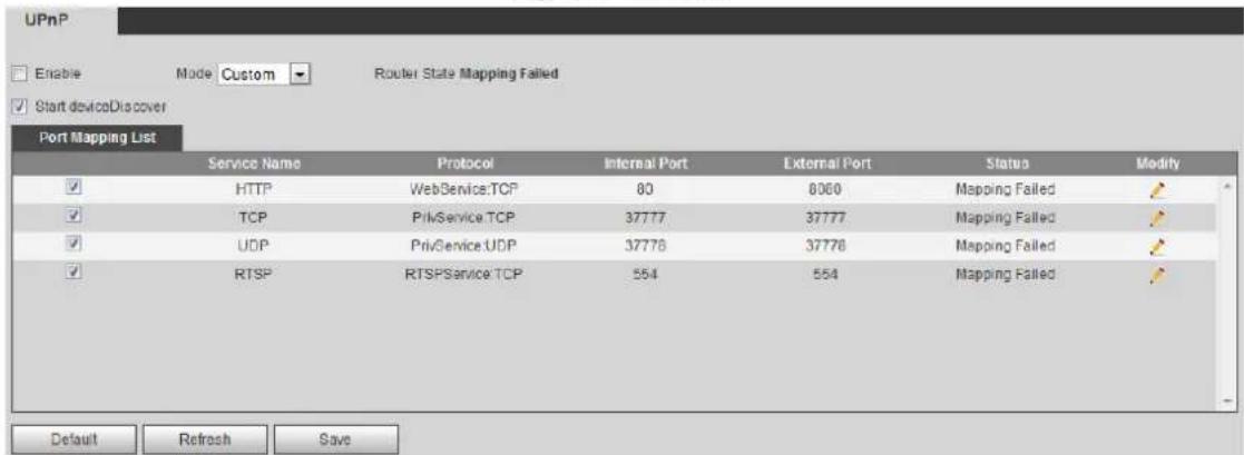
Step 2 Select Enable to enable UPnP function, and there are two mapping modes: Custom and Default.
- Select Custom, and then you can modify external port as needed.
- Select Default, and then the system finishes mapping with available port automatically. You cannot modify mapping relation.
Step 3 Select Start Device Discover as needed.
Step 4 Click Save to make the configurations valid.
4.2.7 SNMP
Simple Network Management Protocol, which can be used to enable software such as MIB Builder and MG-SOFT MIB Browser to connect to the radar and manage and monitor your device.

• Install SNMP monitoring and managing tools such as MIB Builder and MG-SOFT MIB Browser.
- Contact technical support for the MIB file that matches the current version.
Step 1 Select Setting > Network > SNMP.
The SNMP interface is displayed, see Figure 4-29 and Figure 4-30.
Figure 4-29 SNMP (1)
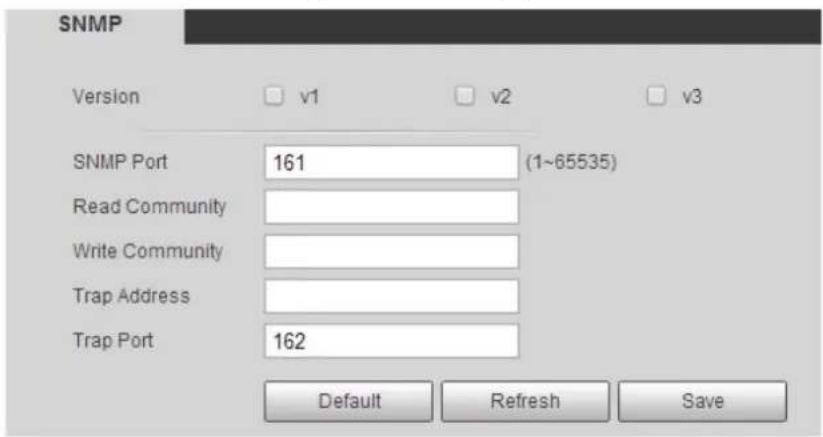
Figure 4-30 SNMP (2)
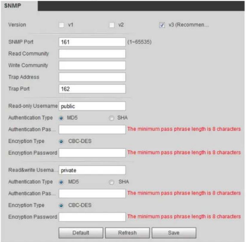
Step 2 Select SNMP version to enable SNMP.
In the Trap Address, enter the IP address of the PC that has MIB Builder and MG-SOFT MIB Browser installed, and leave other parameters as the default.
Table 4-14 SNMP parameter descriptions
| Parameter Description | |
| Version | Select the check box of the version you need, and the system can process information of corresponding version.Select V1, and the system can only process information of V1 version.Select V2, and the system can only process information of V2 version.Select V3, and then V1 and V2 become unavailable. You can configure username, password and authentication type, which are needed to access radar from the server. Using V1 and V2 might cause data leakage, and V3 is recommended. Using V1 and V2 might cause data leakage, and V3 is recommended. |
| SNMP Port | The listening port of the software agent in the radar. |
| Read Community,Write Community | The read and write community strings that the software agent supports. You can enter number, letter, underline and dash to form the name. You can enter number, letter, underline and dash to form the name. |
| Trap Address | The target address of the trap information sent by the software agent of the radar. |
| Trap Port | The target port of the trap information sent by the software agent of the radar. |
| Read-only Username | The name is public by default.You can enter number, letter, and underline to form the name. |
| Read & write Username | The name is private by default.You can enter number, letter, and underline to form the name. |
| Authentication Type | You can select from MD5 and SHA. The default type is MD5. |
| Authentication Password | It should be no less than 8 digits. |
| Encryption Type | The default is CBC-DES. |
| Encryption Password | It should be no less than 8 digits. |
Step 3 Click Save.
Step 4 View radar information.
1) Run MIB Builder and MG-SOFT MIB Browser.
2) Compile the two MIB files with MIB Builder.
3) Load the generated modules with MG-SOFT MIB Browser.
4) Enter the IP address of the device you need to manage in the MG-SOFT MIB Browser, and then select version to search.
5) Unfold all the tree lists displayed in the MG-SOFT MIB Browser, and then you can view the configuration information such as video channel and software version.

Use PC with Windows operating system and disable SNMP Trap service. The MG-SOFT MIB Browser will display prompt when alarm is triggered.
4.2.8 Bonjour
Bonjour, known as zero-configuration networking, can automatically discover the PC, device and service on the IP network. With Bonjour, the radar can discover each other automatically without entering IP address or configuring DNS server.
After Bonjour function is enabled, your device will be automatically detected in the operating system and client which support Bonjour. When the radar is automatically detected by Bonjour, it will display the server name which is configured by the user.
Step 1 Select Setting > Network > Bonjour.
The Bonjour interface is displayed. See Figure 4-31.
Figure 4-31 Bonjour
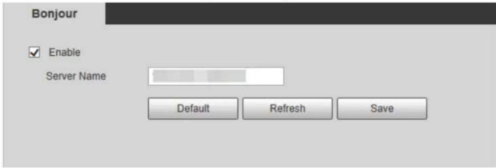
Step 2 Select Enable, and then configure server name.
Step 3 Click Save.
In the operating system and clients that support Bonjour, follow steps below to visit the radar web interface with Safari browser.
Step 1 Click Show all bookmarks in Safari.
Step 2 Enable Bonjour, and then, in your LAN, all the radars which enable Bonjour are displayed.
Step 3 Click the radar to visit the corresponding web interface.
4.2.9 Multicast
When multiple users are watching the live video simultaneously through network, it might fail due to limited bandwidth. The problem can be solved by setting a multicast IP for the radar and adopting the multicast protocol.
Step 1 Select Setting > Network > Multicast.
The RTP interface is displayed. See Figure 4-32.
Figure 4-32 RTP
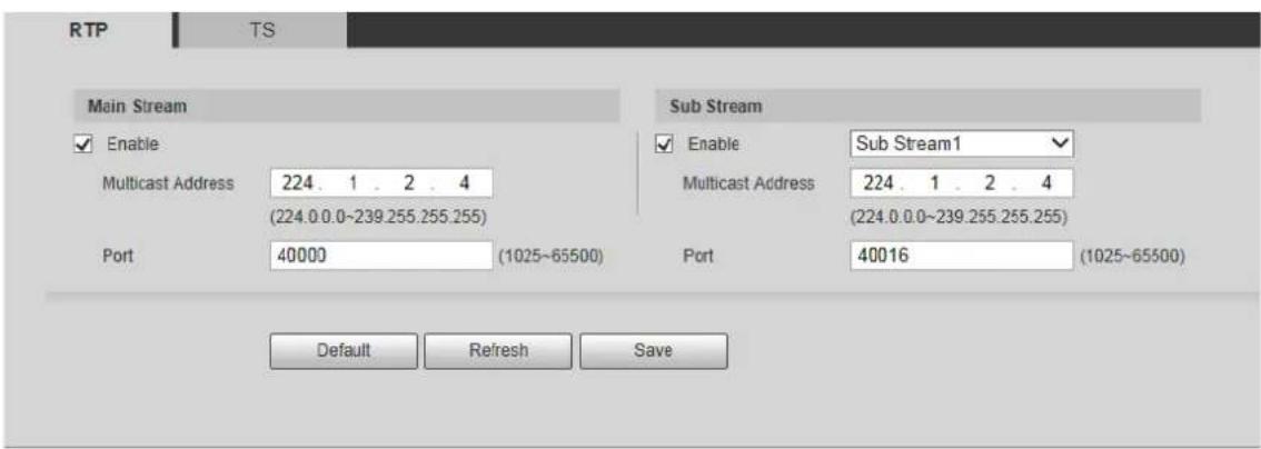
Step 2 Select Enable to enable main stream or sub stream multicast, and select the sub stream from the drop-down list if you enable sub stream multicast.
Step 3 Enter multicast address and port number. For detailed description, see Table 4-15.
Table 4-15 Multicast parameter descriptions
| Parameter | Description |
| Multicast Address | The multicast IP address of main stream and sub stream is 224.1.2.4 by default, and the range is 224.0.0.0–239.255.255.255. |
| Port | Set the multicast port of corresponding stream.Main Stream: 40000; Sub Stream1: 40016; Sub Stream2: 40032. All the range is 1025–65500. |
Step 4 Click Save.

The multicast configuration of TS is similar to RTP, and you can refer to the previous steps.
4.2.10 802.1x
802.1x (port based network access control protocol) supports manual selection of authentication method. Device can be connected to LAN after passing 802.1 x authentications. It well supports authentication, charging, safety and management requirement of network.
Step 1 Select Setting > Network > 802.1x.
The 802.1x interface is displayed. See Figure 4-33.
Figure 4-33 802.1x
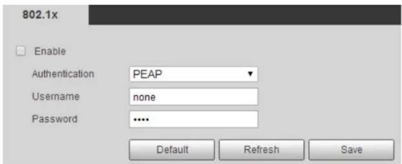
Step 2 Select Enable to enable 802.1x.
Step 3 Configure parameters. See Table 4-16.
Table 4-16 802.1x parameter descriptions
| Parameter Description | |
| Authentication PE | AP (protected EAP protocol). |
| Username | The username that was authenticated on the server. |
| Password | Corresponding password. |
Step 4 Click Save.
4.2.11 QoS
You can solve problems such as network delay and congestion with this QoS (Quality of Service). It helps to assure bandwidth, and reduce transmission delay, packet loss rate, and delay jitter to improve service quality.
For DSCP (Differentiated Services Code Point), it has 64 degrees (0–63) of priority for packets; 0 is the lowest and 63 is the highest. It can select different queues and the bandwidth of each queue according to the priority. When the network is congested, bandwidth of different queues will be discarded with different ratios so as to guarantee service quality.
Step 1 Select Setting > Network > QoS.
The QoS interface is displayed. See Figure 4-34.
Figure 4-34 QoS
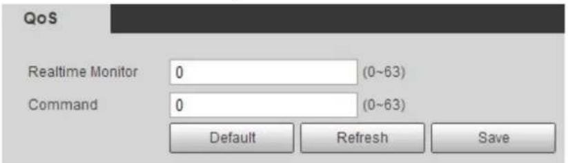
Step 2 Configure parameters. See Table 4-17.
Table 4-17 QoS parameter descriptions
| Parameter Description | |
| Realtime Monitor | Configure the priority of the data packets that used for network monitoring. 0 is the lowest and 63 is the highest. |
| Command | Configure the priority of the data packets that used for configuration or search. 0 is the lowest and 63 is the highest. |
Step 3 Click Save.
4.2.12 Access Platform
4.2.12.1 P2P
P2P (peer-to-peer) is a private network traversal technology which enables user to manage devices easily without requiring DDNS, port mapping or transit server.
Scan the QR code with your smartphone, and then you can add and manage devices on your mobile client.
Step 1 Select Setting > Network > Access Platform > P2P.
The P2P interface is displayed. See Figure 4-35.
Figure 4-35 P2P
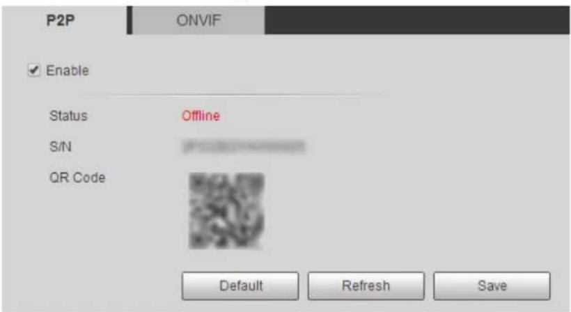

P2P is enabled by default. When P2P is enabled, the radar will be connected to the network, and the status is displayed as online. We might collect the information including IP address, MAC address, device name, device SN and so on. The information collected is for remote accessing only. Clear Enable check box if you do not agree with our information collection.
Step 2 Log in to mobile phone client, and then tap the cross icon at the upper-right corner of the app on the Device interface.
Step 3 Scan the QR code on the P2P interface.
Step 4 Follow on-screen instructions to finish the configurations.
4.2.12.2 ONVIF
The ONVIF (Open Network Video Interface Forum) allows the network video products (including video recording device and other recording devices) from different manufacturers to mutually communicate with each other.

ONVIF is on by default.
Step 1 Select Setting > Network > Access Platform > ONVIF.
The ONVIF interface is displayed. See Figure 4-36.
Figure 4-36 ONVIF
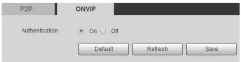
Step 2 Select On.
Step 3 Click Save.
Event Management 4.3
You can enable external and abnormality alarms, and configure linked actions such as recording, capturing, and sending email, and so on.
4.3.1 Alarm
You can set the linkage actions when alarm events are triggered.
Step 1 Select Setting > Event > Alarm.
The Alarm interface is displayed. See Figure 4-37.
Figure 4-37 Alarm linkage
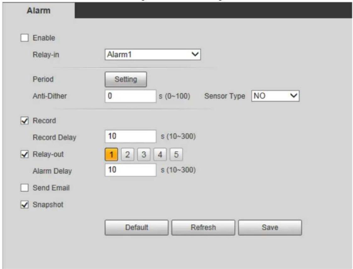
Step 2 Select Enable check box to enable the alarm linkage, and configure parameters as needed.
- Configure arming period.
1) Click Setting.
The Period interface is displayed. See Figure 4-38.
Figure 4-38 Set arm period
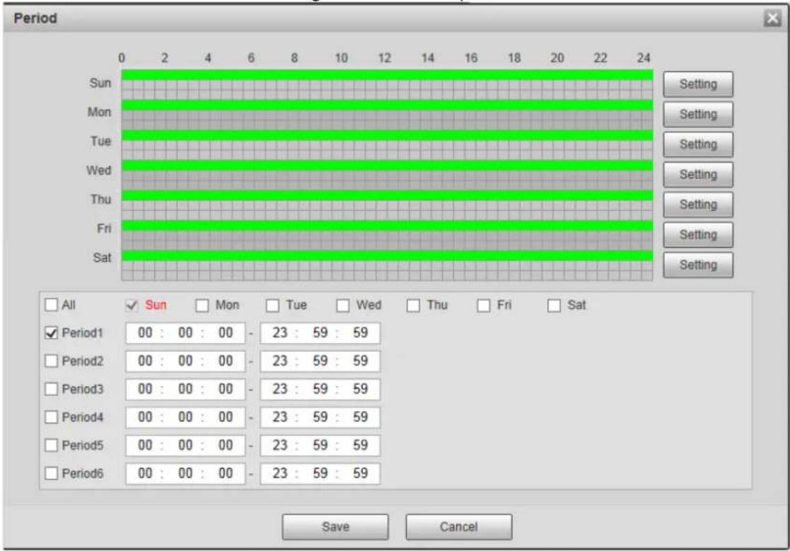
2) Set arming periods, and the alarm can only be triggered when it occurs during the defined period. The time period in green on the timeline is armed.
◇ Method one: Click Setting of the day you want to set. Directly press and drag the left mouse button on the timeline.
◇ Method two: Click Setting of the day you want to set. Select the check box in front of the time period to enable it. Enter start time and end time of that time period.

- Select All or the check box of any other day, and the set time period will apply to the selected days.
• You can set 6 time periods per day.
3) Click Save to return to the Alarm interface.
Set other parameters. For details, see Table 4-18.
Table 4-18 Alarm linkage parameter descriptions
| Parameter Description | |
| Enable | Select Enable check box to enable alarm linkage. |
| Relay-in | Select alarm input. |
| Anti-Dither | The system records only one motion detection event within the defined time (from 0 s to 100 s). |
| Sensor Type | Two options: NO (Normally Open) and NC (Normally Closed). Switch from NO to NC means enabling alarm. Switch from NC to NO means disabling alarm. |
| Record | By selecting Record, the system will record automatically when the alarm is triggered.[IMAGE]Before enabling this function, you need to configure record period in Setting > Storage > Schedule > Record. For details, see "4.4.1.1 Record Schedule." In Setting > Storage > Record Control, select Auto for the Record Mode. |
| Record Delay | The alarm record keeps running for the defined time (from 10 s to 300 s) after the alarm is ended. |
| Relay-out | By selecting Relay-out, the corresponding alarm output device will be linked through alarm output port when the alarm is triggered. |
| Alarm Delay | The alarm keeps running for the defined time (from 10 s to 300 s) after the alarm is ended. |
| Send Email | By selecting Send Email, the system automatically sends email to the specified mailbox when the alarm is triggered. You can configure the mailbox in Setting > Network > SMTP (Email). For details, see " 4.2.7 SNMP." |
| Snapshot | By selecting Snapshot, the system automatically captures images when the alarm is triggered.[IMAGE]Before enabling this function, you need to configure record period in Setting > Storage > Schedule > Snapshot. For tetails, see "4.4.1.2 Snapshot Schedule." |
Step 3 Click Save.
4.3.2 Abnormality
You can set the linkage actions when abnormal events are triggered covering SD card, network, illegal access, and scene changing.
4.3.2.1 SD Card
When any abnormality happens to the SD card, the alarm will be triggered.
Step 1 Select Setting > Event > Abnormality > SD Card.
The SD Card interface is displayed. See Figure 4-39.
Figure 4-39 SD card
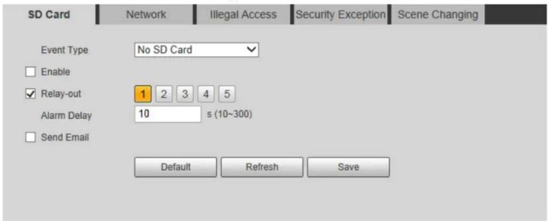
Step 2 Configure parameters as needed. For details, see Table 4-19.

For other parameter descriptions, see Table 4-18.
Table 4-19 SD card parameter descriptions
| Parameter Description | |
| Event Type | Select SD card abnormality from no SD card, SD card error, and capacity warning. |
| Enable | Select Enable check box to enable SD card abnormality detection. |
| Capacity Limit | This parameter is available when Capacity Warning is selected in Event Type. Configure the free space percentage, and if the free space in the SD card is lower than the defined percentage, the alarm is triggered. |
Step 3 Click Save.
4.3.2.2 Network
When any abnormality happens to the network, the alarm will be triggered.
Step 1 Select Setting > Event > Abnormality > Network. The Network interface is displayed. See Figure 4-40.
Figure 4-40 Network
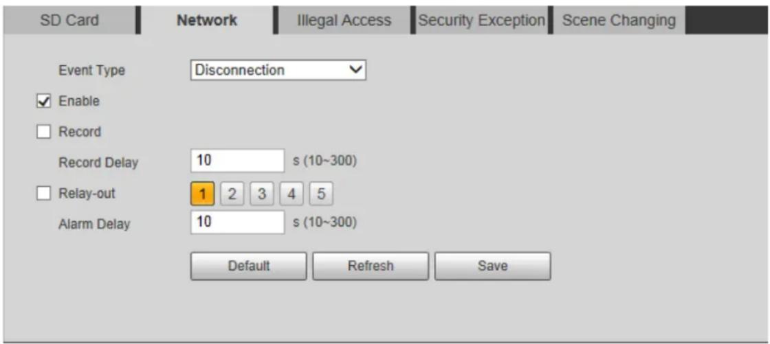
Step 2 Configure parameters. See Table 4-20.

For other parameter descriptions, see Table 4-18.
Table 4-20 Network parameter description
| Parameter Description | |
| Event Type | Select network abnormality from disconnection and IP conflict. |
| Enable | Select Enable check box to enable to network card abnormality detection. |
Step 3 Click Save.
4.3.2.3 Illegal Access
When the entering times of wrong password have exceeded the defined times, the alarm is triggered.
Step 1 Select Setting > Event > Abnormality > Illegal Access.
The Illegal Access interface is displayed. See Figure 4-41.
Figure 4-41 Illegal access
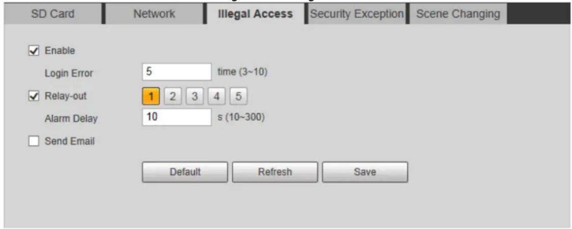
Step 2 Configure parameters as needed. For details, see Table 4-21.

For other parameter descriptions, see Table 4-18.
Table 4-21 Illegal access parameter descriptions
| Parameter Description | |
| Enable | Select Enable check box to enable to network card abnormality detection. |
| Login Error | The number of times that the login password is allowed to be incorrectly entered. When the password has been incorrectly entered for more than the defined times, the account is locked. |
Step 3 Click Save.
4.3.2.4 Security Exception
When any event that will influence radar's security happens, the alarm will be triggered.
Step 1 Select Setting > Event > Abnormality.
The Security Exception interface is displayed. See Figure 4-42.
Figure 4-42 Security exception
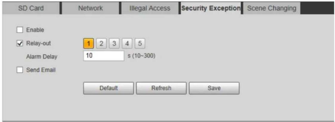
Step 2 Configure parameters as needed.

For other parameter descriptions, see Table 4-18.
Step 3 Click Save.
4.3.2.5 Scene Changing
When scene changing happens, the alarm will be triggered. See conditions below.
- The vertical detection range of the radar is covered for more than 50%.
- The radar is rotated for more than 30^ . But in open areas, 30^ rotation of the radar might not trigger the alarm.
Step 1 Select Setting > Event > Abnormality > Scene Changing.
The Scene Changing interface is displayed. See Figure 4-43.
Figure 4-43 Scene changing
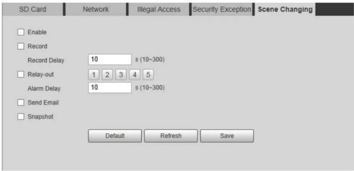
Step 2 Select Enable check box to enable scene changing alarm, and then configure other parameters as needed. For details, see Table 4-18.
Step 3 Click Save.
Storage 4.4
This chapter introduces configurations of schedules for records, snapshots, and holiday, storage methods, and record control.
4.4.1 Schedule
You can configure schedules of records, snapshots, and holidays.

Before configuring schedule, set Record Mode as Auto in Setting > Storage > Record Control. If you select Off, the system will not record video or take snapshot as scheduled.
4.4.1.1 Record Schedule
The system starts or stops video recording as scheduled.
Step 1 Select Setting > Storage > Schedule > Record.
The record schedule interface is displayed. See Figure 4-44.
Figure 4-44 Record schedule
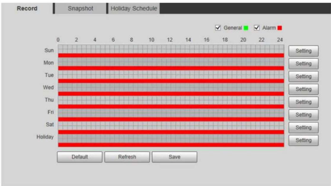
Step 2 Set a record plan.
- Method one: Select a record type, such as Alarm, and then press and drag the left mouse button to draw the time period for alarm record on the timeline.
• Method two: Enter an actual time period.
1) Click Setting of the day you want to set.
The Setting interface is displayed. See Figure 4-45.
Figure 4-45 Set schedule
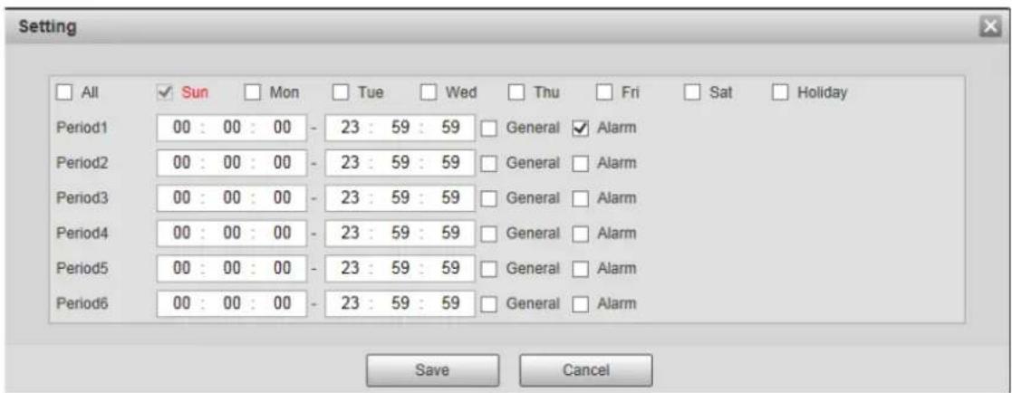
2) Enter start time and end time of the time period, and select record type from General and Alarm.

- Select All or the check box of any other day, and the set time period will apply to the selected days.
• You can set 6 time periods per day.
3) Click Save to return to the Record interface.

Each color matches with a different record schedule.
- Green: General video record. The system records continuously within the set period.
- Red: Alarm video record. The system records when the alarm event happens within the set period.
Step 3 Click Save.
4.4.1.2 Snapshot Schedule
The system starts or stops taking snapshot as scheduled.
Step 1 Select Setting > Storage > Schedule > Snapshot.
The snapshot schedule interface is displayed. See Figure 4-46.
Figure 4-46 Snapshot schedule
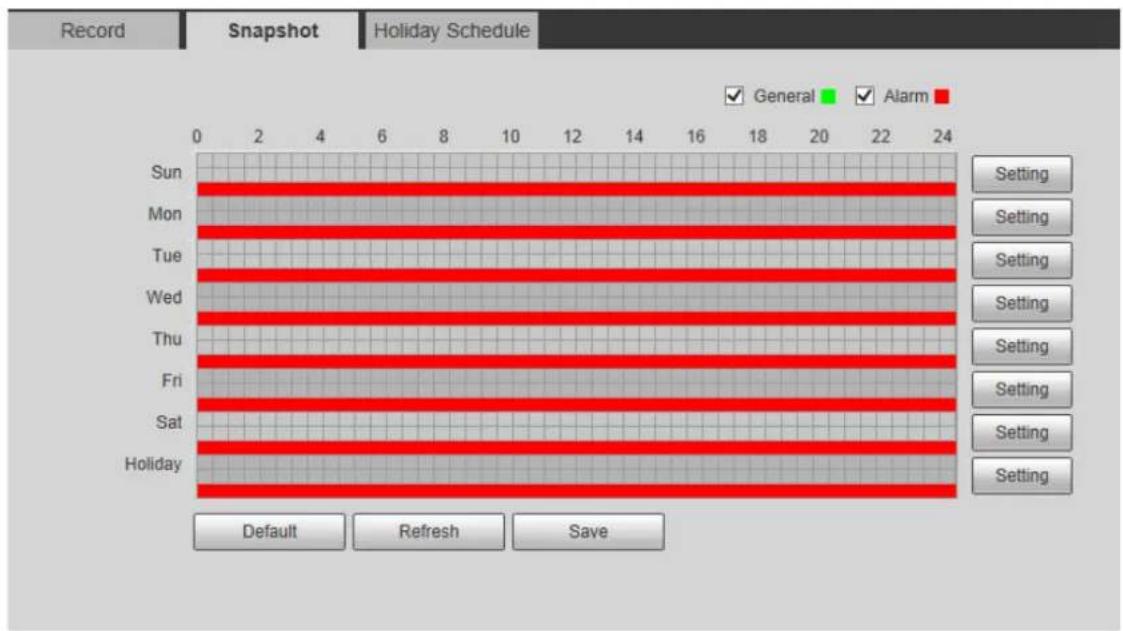
Step 2 Configure time periods. For details, see previous record schedule settings.
Step 3 Click Save.
4.4.1.3 Holiday Schedule
Set certain days as holiday, and when the Record or Snapshot is selected in the holiday schedule, the system takes snapshot or records as holiday schedule defined.
Step 1 Select Setting > Storage > Schedule > Holiday Schedule. The Holiday Schedule interface is displayed. See Figure 4-47.
Figure 4-47 Holiday schedule
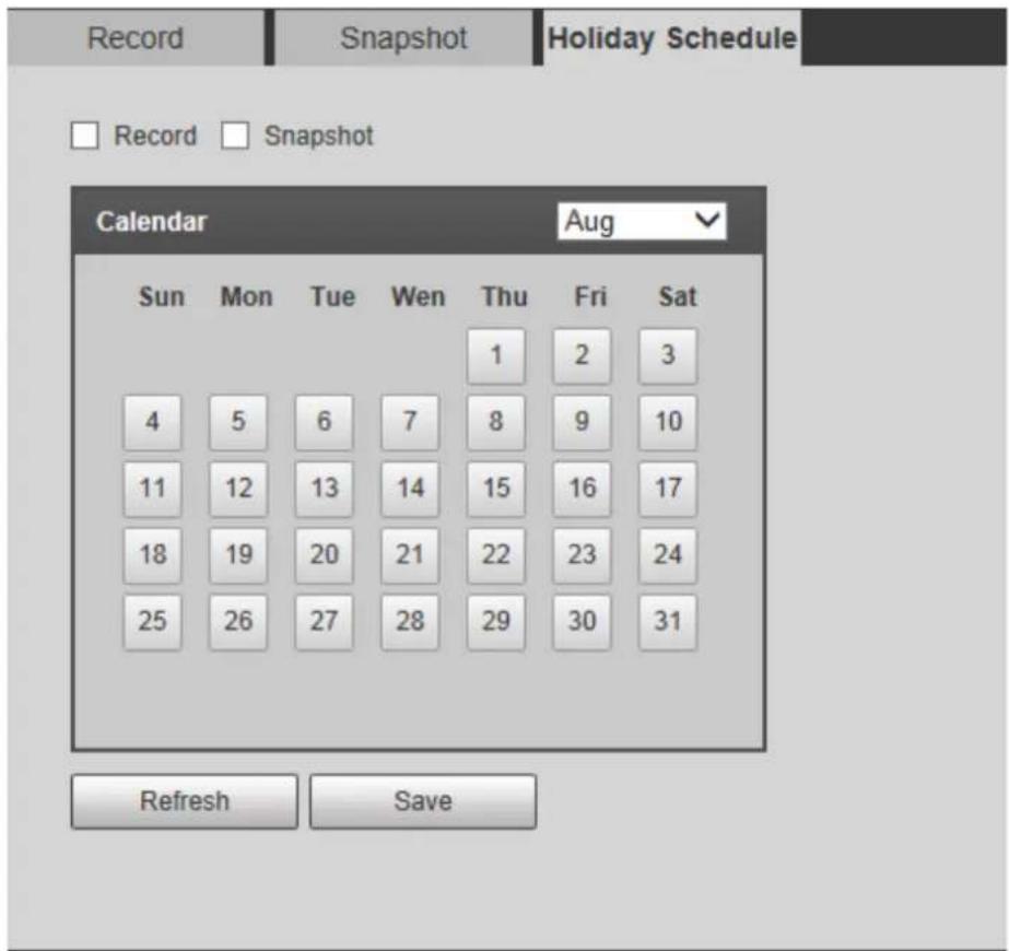
Step 2 Select the days to be set as holiday as needed. The selected days has yellow background.
Step 3 Select from Record and Snapshot, and then click Save.
Step 4 On Record or Snapshot interface, click Setting behind Holiday, and then you can set detection type and detection period. For details, see "4.4.1.1 Record Schedule."
Step 5 Click Save. Record and snapshot will be taken according to the set holiday schedule for the selected days.
4.4.2 Destination
This section introduces the configurations of storage paths for the records and snapshots.
4.4.2.1 Path
You can select storage paths from Local, FTP, or NAS for the records and snapshots.
Step 1 Select Setting > Storage > Destination > Path.
The Path interface is displayed. See Figure 4-48.
Figure 4-48 Path
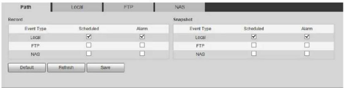
Step 2 Select the storage path for the records and snapshots of different event types as needed. For detailed parameter descriptions, see Table 4-22.
Table 4-22 Path parameter descriptions
| Parameter Description | |
| Event Type | Select fromScheduledandAlarm. It matches with the record types on the schedule interface. |
| Local Save in the internal SD card. | |
| FTP Save in the FTP server. | |
| NAS | Save in the NAS (network Attached Storage). |
Step 3 Click Save.
4.4.2.2 Local
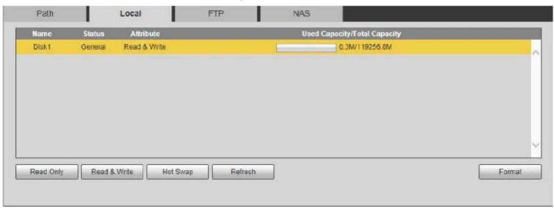
Display the internal SD card information. You can set it as read only or read & write; you can also hot swap or refresh it.
Select Setting > Storage > Destination > Local, and then the Local interface is displayed. See Figure 4-49.
- Click Read Only, and then the SD card is set to read only.
- Click Read & Write, and then the SD card is set to read & write.
- Click Hot Swap to realize hot swap upon the SD card.
- Click Refresh, and then you can format the SD card.
Figure 4-49 Local
4.4.2.3 FTP
When the network fails or is disconnected, you can save all the files to the internal SD card for emergency.

FTP function can be enabled only when the storage path is selected as FTP.
Step 1 Select Setting > Storage > Destination > FTP.
The FTP interface is displayed. See Figure 4-50.
Figure 4-50 FTP
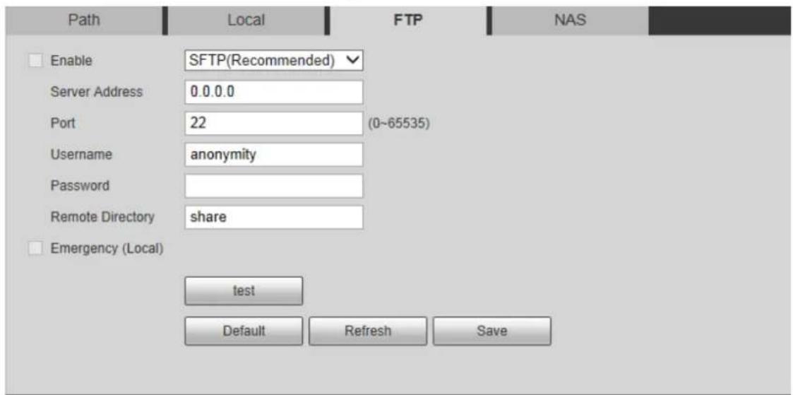
Step 2 Select Enable check box to enable the FTP function.

SFTP is recommended to enhance network security.
Step 3 Configure FTP parameters. See Table 4-23.
Table 4-23 FTP parameter descriptions
| Parameter Description | |
| Server Address | The IP address of the FTP server. |
| Port | The port number of the FTP server. |
| Username | The username to log in to the FTP server. |
| Password | The password to log in to the FTP server. |
| Remote Directory | The destination path in the FTP server. |
| Emergency (Local) | Select Emergency (Local), and when the FTP server fails, all the files are saved to the internal SD card. |
Step 4 Click Test to test if FTP server can be connected to radar.
Step 5 Click Save.
4.4.2.4 NAS

NAS function can be enabled only when the storage path is selected as NAS.
Step 1 Select Setting > Storage > Destination > NAS.
The NAS interface is displayed. See Figure 4-51.
Figure 4-51 NAS
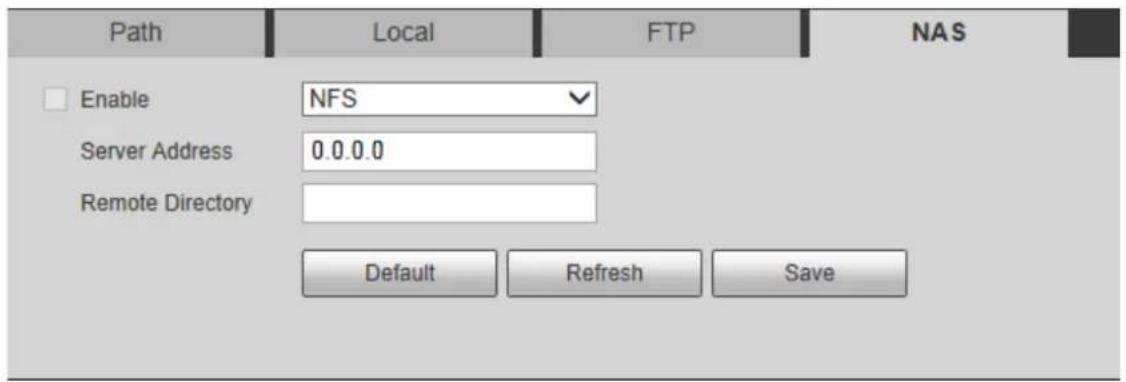
Step 2 Configure NAS parameters. See Table 4-24.
Table 4-24 NAS parameter descriptions
| Parameter Description | |
| Enable | Select Enable check box to enable NFS or SMB function.NFS (Network File System): A file system which enables computers in the same network share files through TCP/IP.SMB (Server Message Block): Provide shared access for clients and the server. |
| Server Address | The IP address of the NAS server. |
| Remote Directory | The destination path in the NAS server. |
Step 3 Click Save.
4.4.3 Record Control
This section introduces record control configurations, including pack duration, pre-event record, disk full, record mode, and record stream.
Step 1 Select Setting > Storage > Record Control.
The Record Control interface is displayed. See Figure 4-52.
Figure 4-52 Record control
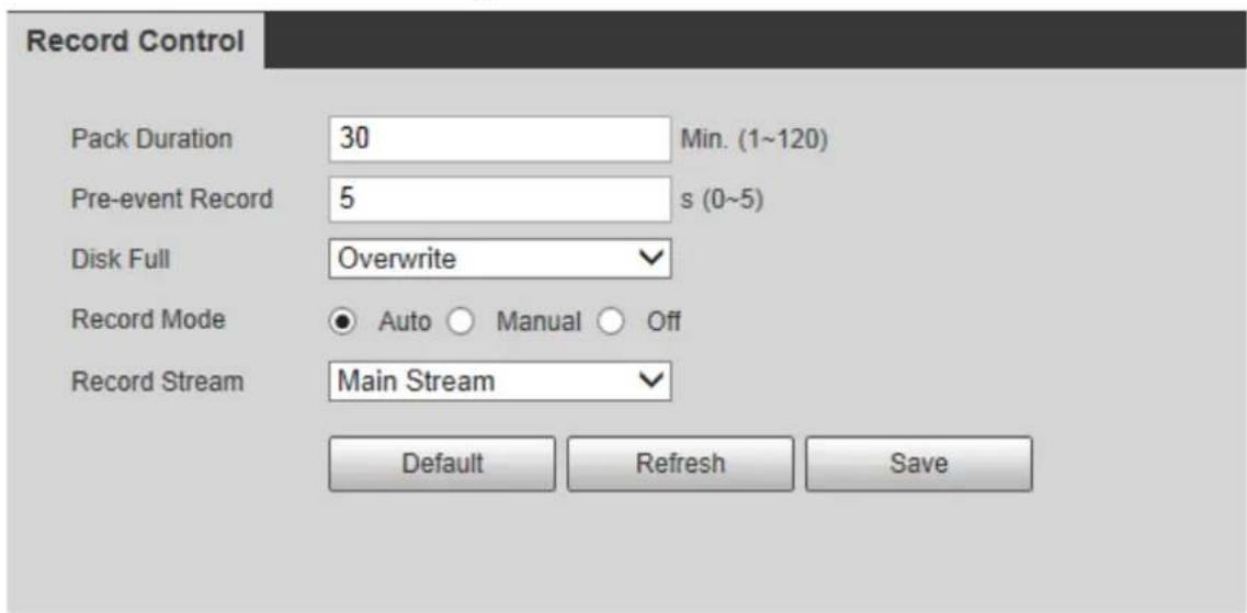
Step 2 Configure record control parameters. See Step 2.
Table 4-25 Record control parameter descriptions
| Parameter Description | |
| Pack Duration | Set the pack duration of each record; it is 30 min by default. |
| Pre-event Record | The time period for which the system records video before alarm starts. If the value is 5, then the system records video for 5 s before alarm starts and then save it to the record. If theRecord Modeis Off, and the record is triggered by an alarm event, the system will save n seconds (the duration set inPre-event Record)of the video, which starts before enabling recording, into the whole record. If theRecord Modeis Off, and the record is triggered by an alarm event, the system will save n seconds (the duration set inPre-event Record)of the video, which starts before enabling recording, into the whole record. |
| Disk Full | Set the record method when the disk is full. You can select from:Stop:The system stops recording when the disk is full.Overwrite:The system overwrites the oldest files and keeps recording when the disk is full. |
| Record Mode | Manual:The system starts recording video manually.Auto:The system records video as time period scheduled.Off:The system will not record video or take snapshots. |
| Record Stream | Include main stream and sub stream. |
Step 3 Click Save.
System 4.5
This chapter introduces system configurations, including general settings, date & time, account, safety, default, import and export configurations, auto maintenance, and upgrade.
4.5.1 General
You can configure radar name, system language and video format.
Step 1 Select Setting > System > General > General.
The General interface is displayed, see Figure 4-53.
Figure 4-53 General
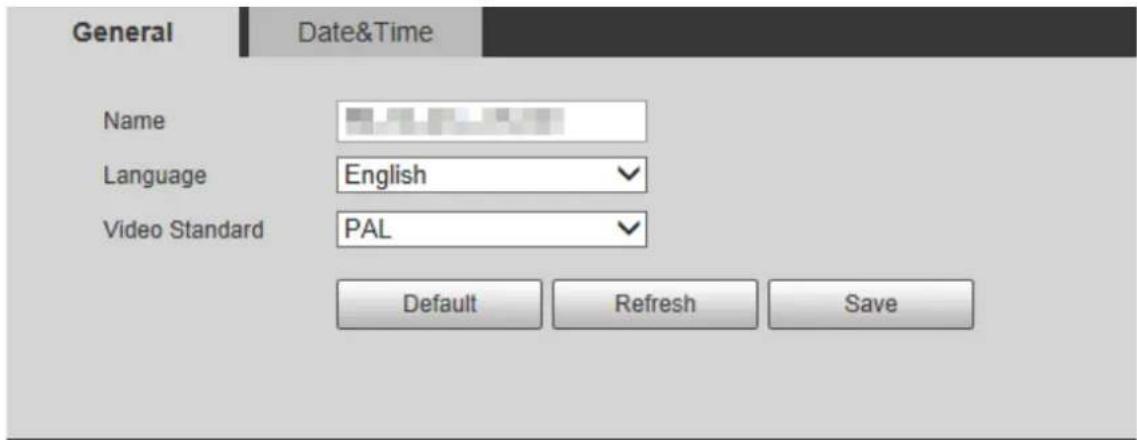
Step 2 Configure General parameters. See Table 4-26.
Table 4-26 General parameter descriptions
| Parameter Description | |
| Name | The name of the radar.Each device has a different name. |
| Language | Select system language. |
| Video Standard | Select video standard from PAL and NTSC. |
Step 3 Click Save.
4.5.2 Date & Time
You can configure date and time format, time zone, current time, DST (Daylight Saving Time), and NTP (Network Time Protocol) server.
Step 1 Select Setting > System > General > Date & Time.
The Date & Time interface is displayed. See Figure 4-54.
Figure 4-54 Date & Time
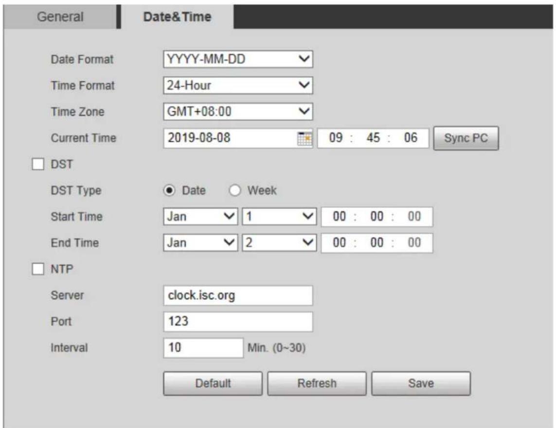
Step 2 Configure Date & Time parameters. See Table 4-27.
Table 4-27 Date & Time parameter descriptions
| Parameter Description | |
| Date Format | Select the date format. |
| Time Format | Select the time format from 12-hour or 24-hour. |
| Time Zone | Select the time zone that the radar is at. |
| Current Time | Configure system time. Click Sync PC, and the system time will sync to the time on PC. |
| DST | Enable DST as needed.Select the check box, and then configure start time and end time of DST with Date or Week. |
| NTP | Select NTP check box to enable NTP function and the system will sync time to the Internet server. |
| Server | Set the address of time server. |
| Port | Set the port of time server. |
| Interval | Set the sync interval between the radar and the time server. |
Step 3 Click Save.
4.5.3 Account
You can add, delete, or modify users and groups. Managing users and groups are only available for administrator users.
- The maximum length of the user or group name is 15 characters. A user name can only consist of numbers, letters, underline, dot and @. A group name can only consist of numbers, letters, and underline.
- The password must consist of 8 to 32 non-blank characters and contain at least two types of characters among upper case, lower case, number, and special character (excluding '";: &). Follow the password security notice to set a high security level password. Make sure that the new password and the confirmed password are the same.
- You can have 18 users and 8 groups at most according to factory settings.
- You can manage users in two methods: Single user or group. Duplicate usernames or group names are not allowed. A user can be in only one group at a time.
• Online users cannot modify their own authority.
• There is one admin by default which has the highest authority.
4.5.3.1 User
You are admin user by default. You can add users, delete added users, modify user password, and log in anonymously.
Select Setting > System > Account > Account > Username. The Username interface is displayed. See Figure 4-55.
Figure 4-55 Username
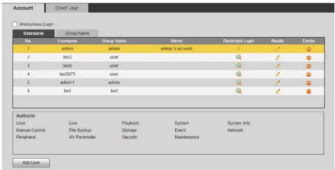
Anonymous Login
By selecting Anonymous Login check box, you can log in with only entering IP address instead of username and password. Anonymous users only have live view authority. Under Anonymous Login, you can log in with other account after clicking Logout.
Adding a User
You can add users to the group, and configure user authority.

As a default user with the highest authority, admin cannot be deleted.
Step 1 Click Add User.
The Add User interface is displayed. See Figure 4-56.
Figure 4-56 Add user
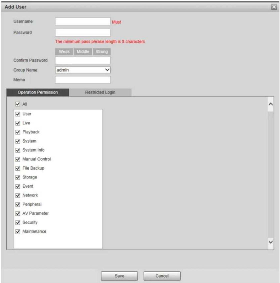
Step 2 Enter username and password, and then select group and operation permission.

- A user can be in only one group at a time, and the group users can own authorities within group authority range.
- It is recommended to give fewer authorities to normal users than premium users.
Step 3 (Optional) Click Restricted Login to set IP address, validity period, and time range of the added user. See Figure 4-57.
Figure 4-57 Restricted login
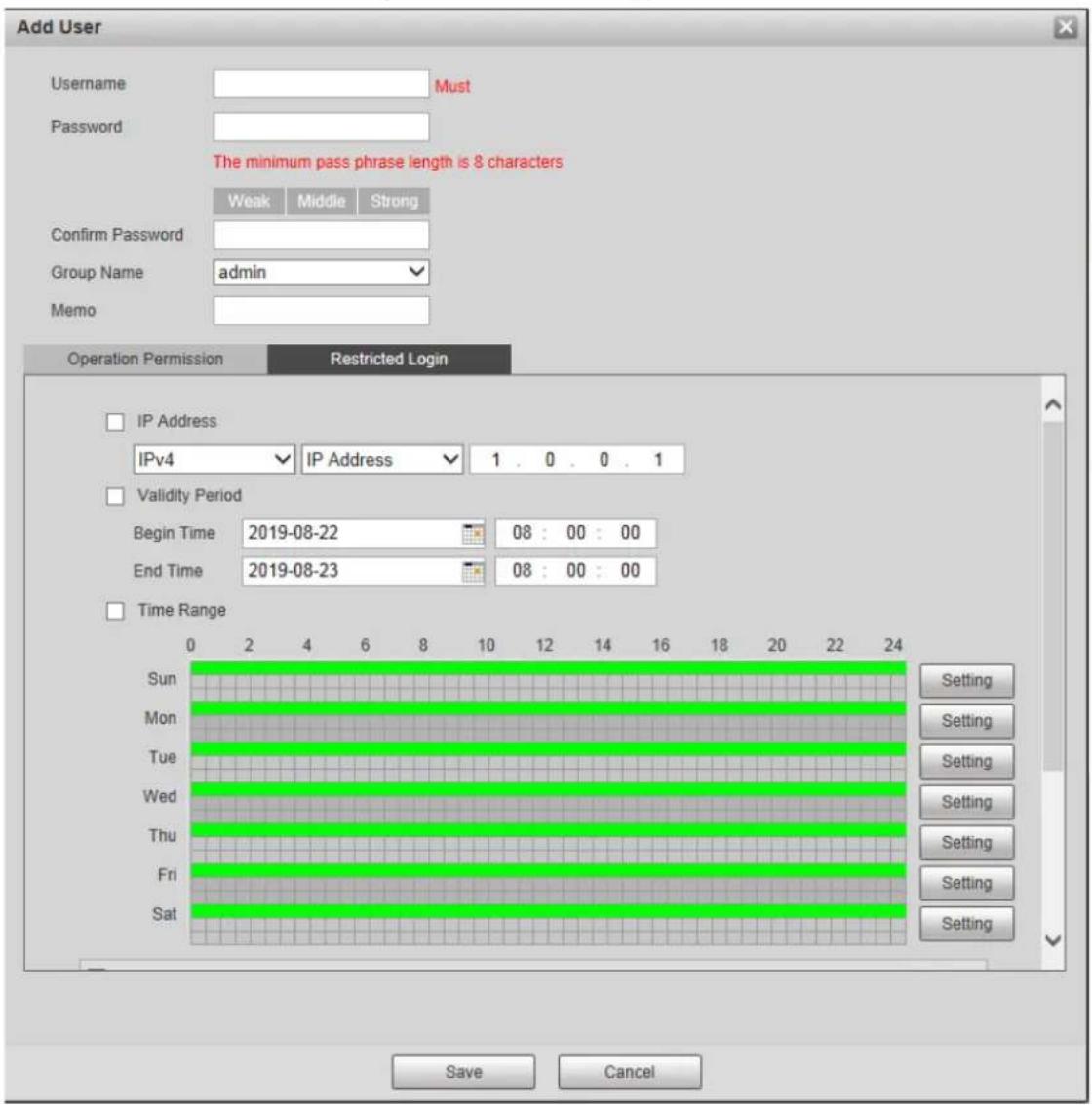
Step 4 Click Save.
Modifying a User
Step 1 Click of the selected user.
The Modify User interface is displayed. See Figure 4-58.
Figure 4-58 Modify user
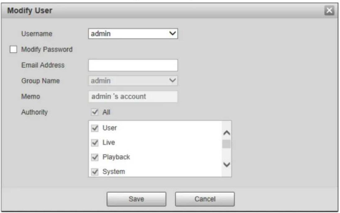
Step 2 Modify user information as needed.
Step 3 Click Save.
Modifying the Password
Step 1 Click of the selected user.
The Modify User interface is displayed.
Step 2 Select Modify Password check box.
Step 3 Enter the old password, new password, and then confirm the password.
Step 4 Click Save.
Deleting a User
Click to delete the added user.
4.5.3.2 Group
You have two groups named admin and user by default, you can add new group, delete added group or modify group authority and memo.
Step 1 Select Setting > System > Account > Account > Group Name.
The Group Name interface is displayed. See Figure 4-59.
Figure 4-59 Group name
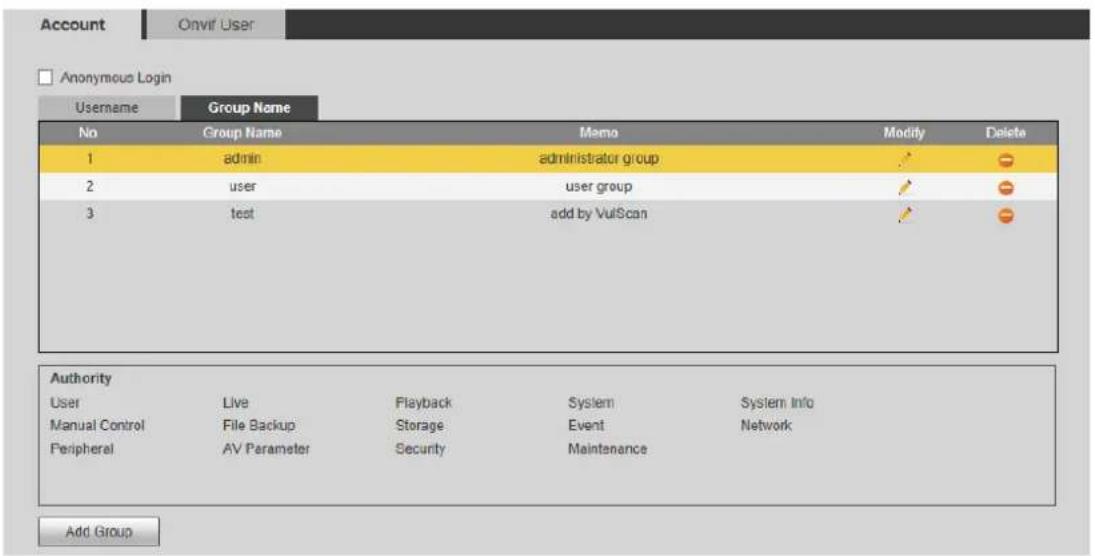
Adding a Group
For details, see "4.5.3.1 User."
Modifying a Group
For details, see "4.5.3.1 User."
Deleting a Group
For details, see "4.5.3.1 User."
4.5.4 Onvif User
You can add, delete, and modify Onvif users.
Step 1 Select Setting > System > Account > Onvif User.
The Onvif User interface is displayed. See Figure 4-60.
Figure 4-60 Onvif user
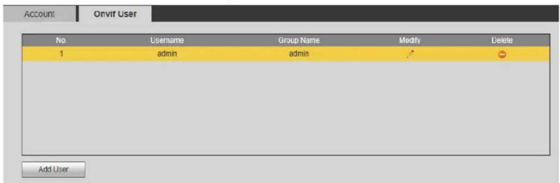
Step 2 Click Add User.
The Add User interface is displayed. See Figure 4-61.
Figure 4-61 Add user
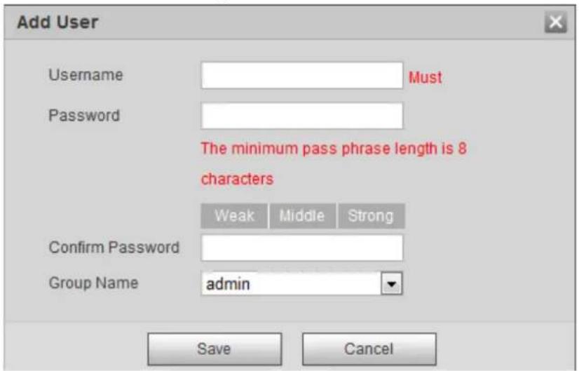
Step 3 Set username, password, and select group.
Step 4 Click Save.

Click to modify user information.
4.5.5 Safety
You can set RTSP authentication, system service, HTTPS, and firewall to ensure the safety of data transmission.
4.5.5.1 RTSP Authentication
Real Time Streaming Protocol (RTSP) ensures the safety of the streaming media during transmission.
Step 1 Select Setting > System > Safety > RTSP Authentication.
The RTSP Authentication interface is displayed. See Figure 4-62.
Figure 4-62 RTSP Authentication
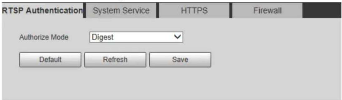
Step 2 Select authorize mode.

- Click Default and the Authorize Mode will be selected as Digest automatically.
- If you select None and click Save, the prompt "Non-authentication mode may have risk. Are you sure to enable it?" will pop up to remind you about the risk. Be careful.
- If you select Basic and click Save, the prompt "Basic authentication mode may have risk. Are you sure to enable it?" will pop up to remind you about the risk. Be careful.
4.5.5.2 System Service
You can configure system services and ensure system security.
Step 1 Select Setting > System > Safety > System Service.
The System Service interface is displayed. See Figure 4-63.
Figure 4-63 System service
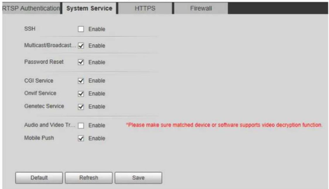
Step 2 Configure system service parameters. See Table 4-28.
Table 4-28 System service parameter descriptions
| Function Description | |
| SSH | Disabled by default. You can enable SSH authentication to perform safety management. |
| Multicast/Broadcast Search | Enabled by default. When multiple users watch the live video simultaneously through network, they can find your device with multicast or broadcast protocol. |
| Password Reset | Enabled by default. You can reset the password if you forget the password.If you disable the function, you can only restore the device to default settings through hardware and then reset the password. |
| CGI Service | Enabled by default, and the radar can be accessed through these protocols. |
| Onvif Service | |
| Genetec Service | |
| Audio and Video TransmissionEncryption | Enable the function to encrypt audio and video transmission.Make sure that matched device or software supports videodecryption.Encryption function is not supported when transmitting audio and video date between the radar and the third party platform and device. To ensure data security, we recommend you to disable CGI service, Onvif service, and Genetec service. |
| Mobile Push | Enabled by default. The system will send the snapshot that was taken when alarm is triggered to your phone. |
Step 3 Click Save.
4.5.5.3 HTTPS
Create certificate or upload the authenticated certificate, and then you can connect through HTTPS with your PC. The HTTPS can ensure safety of data communication, user information, and radar with reliable technology.
Step 1 Create a certificate or upload the authenticated certificate.
- If you need to create certificate, follow the steps below.
1) Select Setting > System > Safety > HTTPS.
The HTTPS interface is displayed. See Figure 4-64.
Figure 4-64 HTTPS (1)
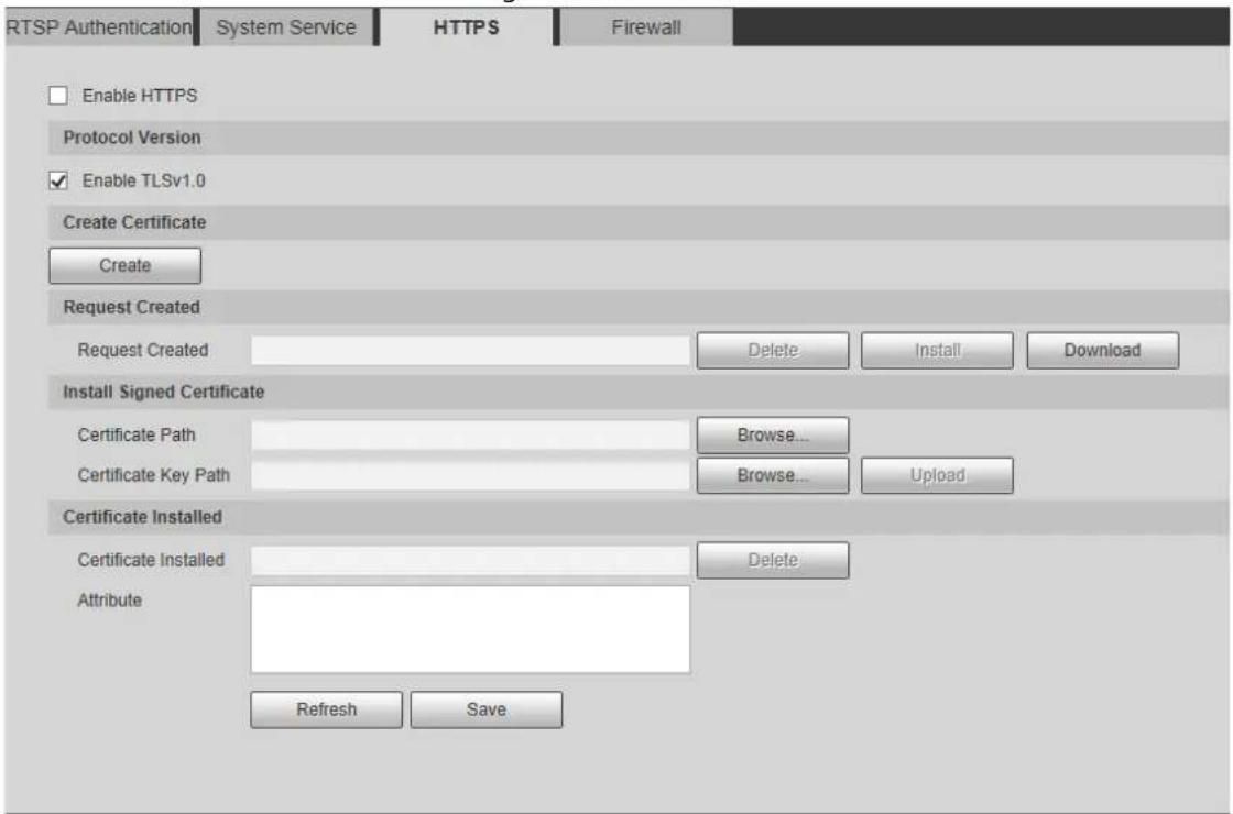
2) Click Create.
3) Enter the required information and then click Create.
If the operation is correct, then the Create Successful prompt is displayed.

The entered IP or Domain name must be the same as the IP or domain name of the radar.
4) Click Install. The certificate begins to be installed. See Figure 4-65.
Figure 4-65 Install certificate
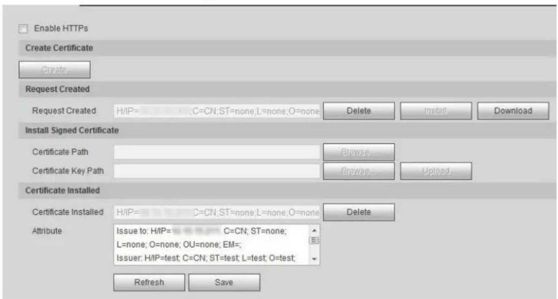
5) Click Download to download root certificate.
The Save As dialog box is displayed. See Figure 4-66.
Figure 4-66 Download certificate
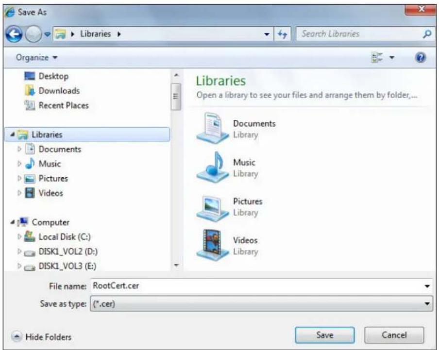
6) Select storage path, and then click Save.
7) Double-click the RootCert.cer icon.
The Certificate interface is displayed. See Figure 4-67.
Figure 4-67 Certificate
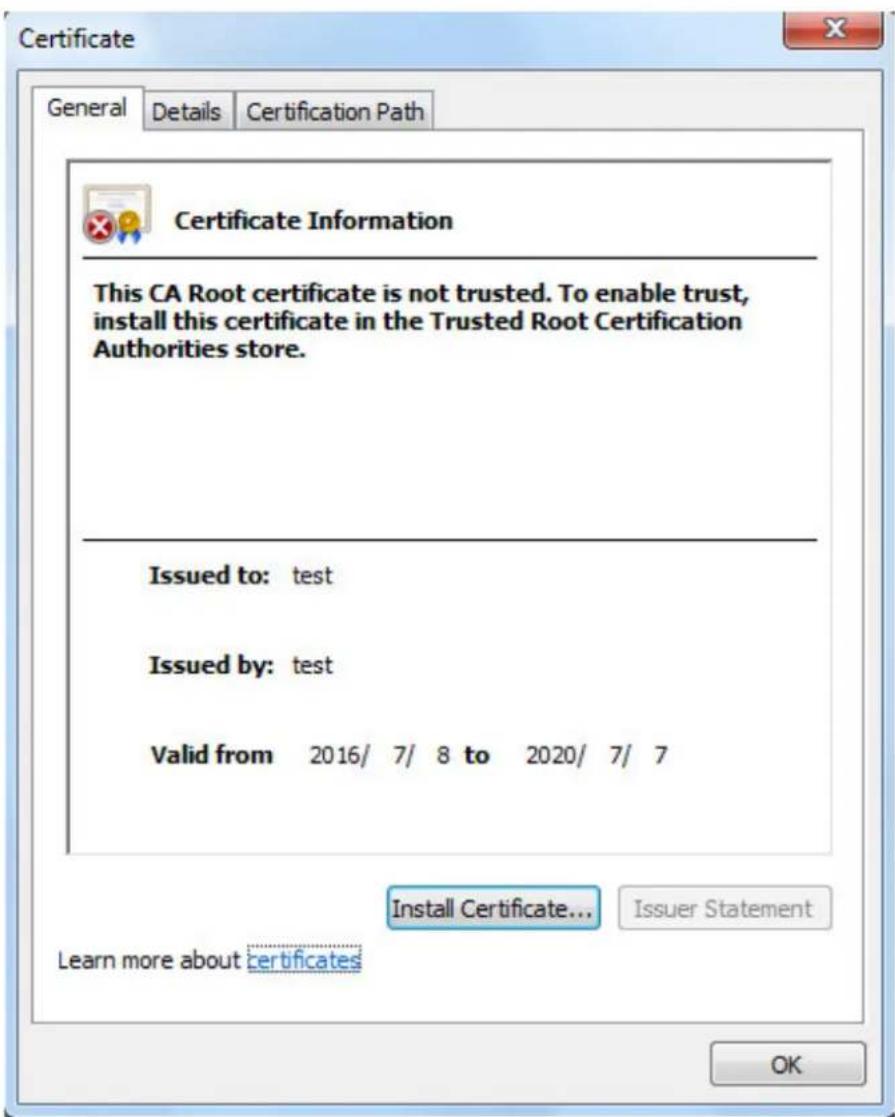
8) Click Install Certificate....
The Certificate Import Wizard interface is displayed. See Figure 4-68.
Figure 4-68 Certificate import wizard
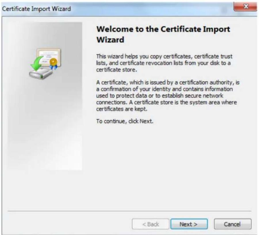
9) Click Next. Select Trusted Root Certification Authorities. See Figure 4-69.
Figure 4-69 Store certificate
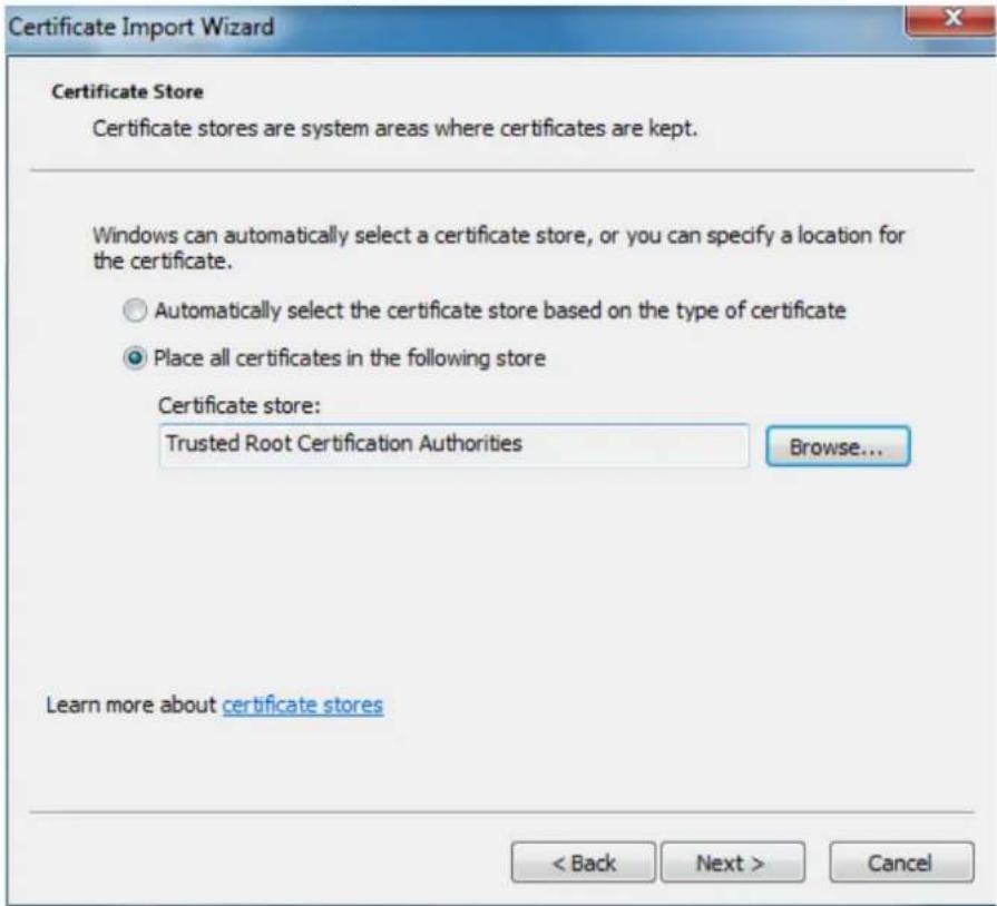
10) Click Next.
The Completing the Certificate Import Wizard interface is displayed. See Figure 4-70.
Figure 4-70 Complete certificate import wizard
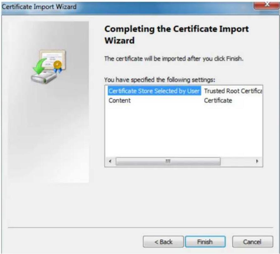
11) Click Finish.
The Security Warning dialog box is displayed. See Figure 4-71.
Figure 4-71 Security warning
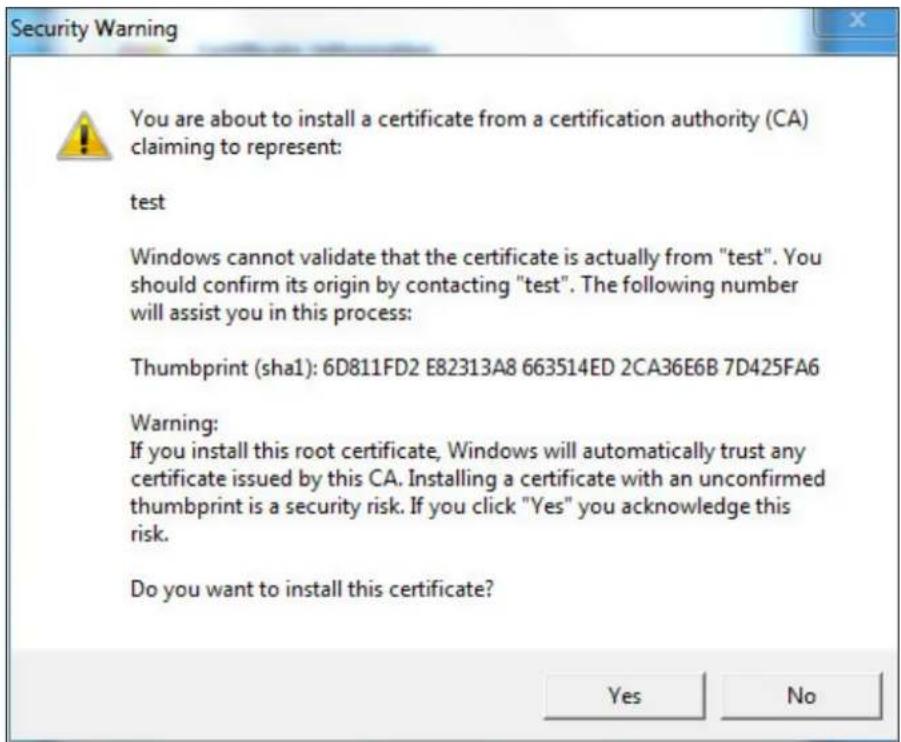
12) Click Yes.
The The import was successful dialog box is displayed. Click OK to finish download. See Figure 4-72.
Figure 4-72 Import successfully
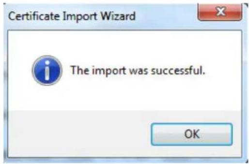
- If you select Install Signed Certificate, follow the steps below.
1) Select Setting > System > Security > HTTPS. The HTTPS interface is displayed.
2) Click Browse to select signed certificate path and certificate key path, and then click Upload.
3) Install root certificate. See the previous steps in creating certificate.
Step 2 Select Enable HTTPS, and then click Save.
The Reboot interface is displayed. See Figure 4-73.
Figure 4-73 Reboot the radar


If HTTPS is enabled, you cannot access the radar through HTTP. It will switch to HTTPS automatically.
4.5.6 Firewall
You can configure network access, refuse PING request, and prevent Semijoin to enhance network and data security.
• Network Access: Set trusted list and banned list to limit access permission.
Trust List: Only the IP/MAC addresses in the list can access the selected port of the radar.
Banned List: The IP/MAC addresses in the list cannot access the selected port of the radar.
- PING Prohibited: By enabling PING Prohibited function, the radar will not response to the ping request.
- Prevent Semijoin: By enabling Prevent Semijoin function, the radar can provide service normally under Semijoin attack.

- You cannot add IP/MAC address of the radar to the trusted or banned list.
- You cannot set port number when MAC address is added to the trusted or banned list.
- When the IP addresses of the radar and your PC are in the same LAN, MAC verification takes effect.
- When you access the radar through Internet, MAC address verifies according to the router MAC.
This section takes Network Access as an example.
Step 1 Select Setting > System > Safety > Firewall.
The Firewall interface is displayed. See Figure 4-74.
Figure 4-74 Firewall
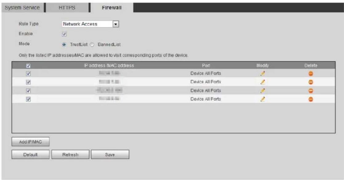
Step 2 Select Network Access from Rule Type list, and then select Enable check box.
- Enable PING Prohibited or Prevent Semijoin, and click Save to complete the configuration. You do not need to configure parameters.
- Enable Network Access, and configure trust list and banned list.
1) Select the mode: TrustList and BannedList.
2) Click Add IP/MAC.
The Add IP/MAC interface is displayed. See Figure 4-75.
Figure 4-75 Add IP/MAC
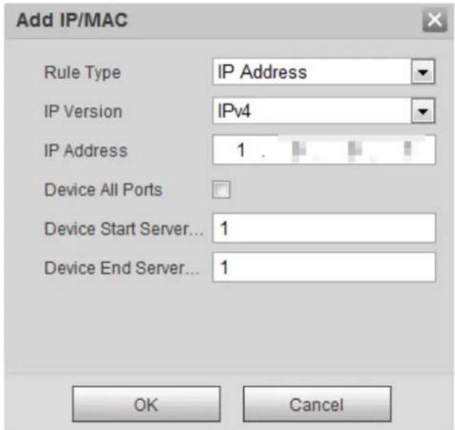
3) Configure parameters. For details, see Table 4-29.
Table 4-29 Parameter descriptions of adding IP/MAC
| Parameter Description | |
| Rule Type | IP address: Select IP version and enter the IP address of the host to be added.IP segment: Select IP version and enter the start address and end address of the segment to be added.MAC address: Enter MAC address of the host to be added.All IP addresses: Set all IP addresses in trust list or banned list. |
| IP Version | IPv4: Enter IP address in IPv4 format, such as 192.108.1.125.IPv6: Enter IP address in IPv6 format, such as ●aa:aa:aa:aa:aa:aa:aa:aa. |
| Device All Ports | Set access ports. You can select all ports or the ports in defined range.Device All Ports: Set all IP port in trust list or banned list. When selecting BannedList in Mode, and All IP Address in Rule Type, you cannot select Device All Ports check box.Device Start Server Port and Device End Server Port: Set device start server port and device end server port, and the range is 1–65535. |
| Device Start Server Port | |
| Device End Server Port |
Step 3 Select OK, and the Firewall interface is displayed.
Step 4 Click Save.
4.5.7 Default
Restore the radar to default configurations or factory settings.
Select Setting > System > Default.
The Default interface is displayed. See Figure 4-76.
Figure 4-76 Default

- Click Default, and then all the configurations except IP address and account management will be restored to default.
- Click Factory Default, and all the configurations will be restored to factory settings.
4.5.8 Import/Export
Export the system configuration file to back up the system configuration. Import system configuration file to make quick configuration or recover system configuration.

The map you imported in linkage configuration cannot be imported or exported.
Select Setting > System > Import/Export.
The Import/Export interface is displayed. See Figure 4-77.
Figure 4-77 Import/Export
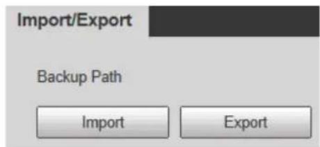
- Click Export to export the configuration file (.backup file) to local.
- Click Import to import the configuration file into the system.
4.5.9 Auto Maintain
You can restart the system manually, or set the time of auto restarting and auto deleting old files.
The system will execute the corresponding actions at the defined time.
Step 1 Select Setting > System > Auto Maintain.
The Auto Maintain interface is displayed. See Figure 4-78
Figure 4-78 Auto Maintain
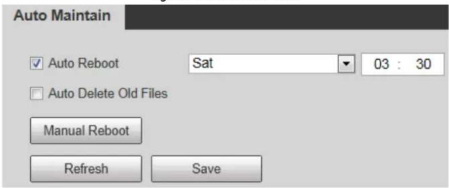
Step 2 Configure auto maintain parameters. See Table 4-30.
Table 4-30 Auto maintain parameter descriptions
| Parameter Description | |
| Auto Reboot | SelectAuto Reboot, and then configure the auto rebooting time. |
| Auto Delete Old Files | SelectAuto Delete Old Filescheck box, and then configure the time; the time range is 1 to 31 days. When you enable and confirm theAuto Delete Old Files, the deleted files cannot be restored. Be careful. When you enable and confirm theAuto Delete Old Files, the deleted files cannot be restored. Be careful. |
Step 3 Click Save.
4.5.10 Upgrade
You can upgrade the system to the latest version to improve radar function and stability.

If wrong upgrade file has been used, please restart the radar, otherwise some functions might not work properly.
Step 1 Select Setting > System > Upgrade.
The Upgrade interface is displayed. See Figure 4-79.
Figure 4-79 Upgrade
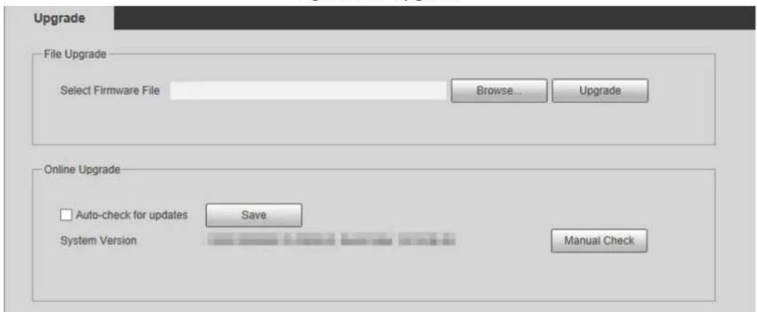
Step 2 Select upgrade method.
- File Upgrade
1) Click Browse..., and then upload upgrade file. The upgrade file should be a .bin file.
2) Click Upgrade. The upgrade starts.
- Online Upgrade
1) Select the Auto-check for updates check box. It will enable the system to check for upgrade once a day automatically and there will be system notice if any upgrade is available.

In order to inform you to upgrade in time, we need to collect the information such as device name, device IP address, firmware version, and device serial number. All the collected information is only used to verify device legality and send upgrade messages.
2) If there is any upgrade available, click Upgrade, and then the system starts upgrading.

Click Manual Check, and you can check for upgrade manually.
Information 4.6
You can view version, log, working time, upgrade times of the system, and more.
4.6.1 Version
You can view hardware information, system version, and web version of the radar.

Versions of different devices might vary, and the actual interface shall prevail.
Select Setting > Information > Version, and then the Version interface is displayed. See Figure 4-80.
Figure 4-80 Version
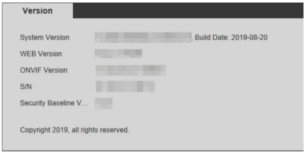
bar
| Version | Build Date: 2019-08-20 | | :--- | :--- | | System Version | [Value not fully visible] | | WEB Version | [Value not fully visible] | | ONVIF Version | [Value not fully visible] | | S/N | [Value not fully visible] | | Security Baseline V... | [Value not fully visible] | Copyright 2019, all rights reserved.4.6.2 Log
You can view and backup operation and system logs.
Step 1 Select Setting > Information > Log.
The Log interface is displayed. See Figure 4-81.
Figure 4-81 Log
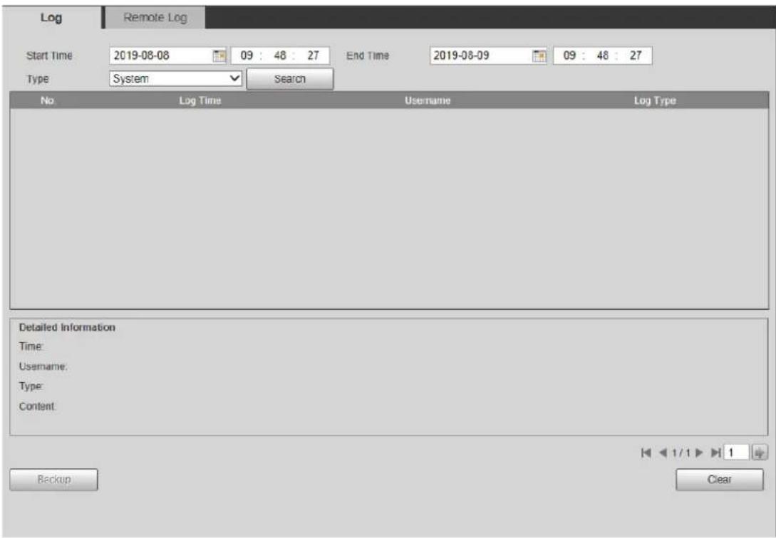
Step 2 Configure Start time and End time, and then select log type.

- The start time should be later than January 1st, 2000, and the end time should be earlier than December 31, 2037.
- The log type includes All, System, Setting, Data, Event, Record, Account, and Safety.
◇ System: Include program launching, force exit, exit, program restarting, device turn off/restarting, system restarting, and system upgrade.
Setting: Include save configuration and delete configuration files.
◇ Data: Include configuring disk type, erasing data, hot swap, FTP status, and record mode.
◇ Event (Record events such as video detection, smart plan, alarm, and abnormality): Include event start and event end.
Record: Include file access, file access error, and file search.
Account: Include login, logout, add user, delete user, modify user, add group, delete group, and modify group.
Safety: Include safety related information such as password reset and IP filter.
Step 3 Click Search.
The needed logs are displayed.

- Click a certain log, and then you can view the detailed information in Detailed Information area.
- Click Backup, and then you can back up all the found logs to your PC.
- Click Clear to clear all logs.
4.6.3 Remote Log
You can upload the log information to the log server.
Step 1 Select Setting > Information > Log > Remote Log. The Remote Log interface is displayed. See Figure 4-82.
Figure 4-82 Remote log
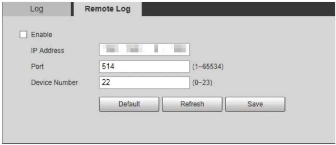
Step 2 Select Enable check box to enable the remote log function.
Step 3 Set the IP address, port, and device number as needed.
Step 4 Click Save.

You can click Default to restore the settings.
4.6.4 Online User
You can view username, user local group, IP address, and user login time of the online users.
Select Setting > Information > Online User.
The Online User interface is displayed. See Figure 4-83.
Figure 4-83 Online user
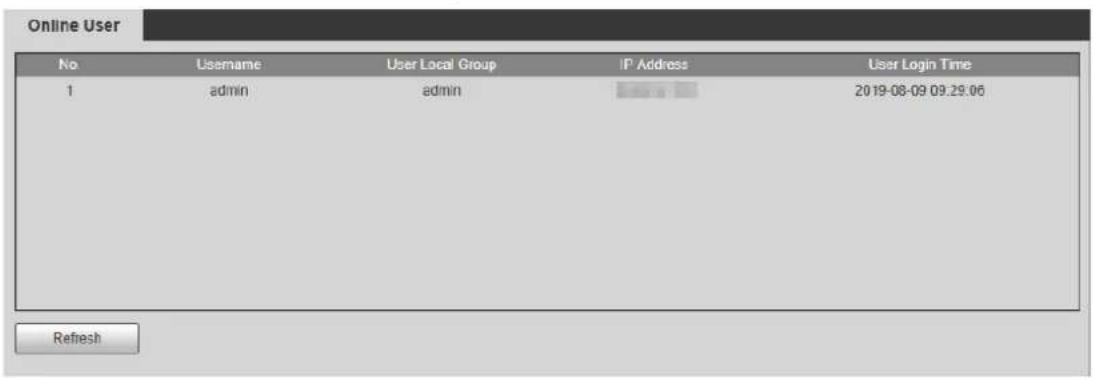
5 Alarm
You can subscribe alarm messages and view the triggered alarm event information on the right column of Alarm interface. Alarm prompt and alarm tone can also be selected as a reminder.
Click Alarm tab, and then the Alarm interface is displayed. See Figure 5-1. For more parameter descriptions, see Table 5-1.
Figure 5-1 Alarm
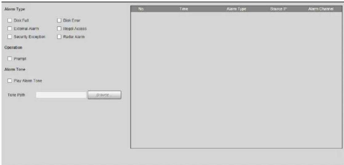
Table 5-1 Alarm parameter descriptions
| Parameter Name Description | ||
| Alarm Type | Disk Full | Select to record the alarm when disk is full. |
| Disk Error | Select to record the alarm when disk malfunctions. | |
| External Alarm | Select to record the alarm when radar receives external alarm. | |
| Illegal Access | Select to record the alarm when unauthorized access occurs. | |
| Security Exception | Select to record the alarm when security exception occurs. | |
| Radar Alarm | Select to record the alarm when an alarm is triggered in the configured detection region. | |
| Operation Prompt | When an alarm is triggered, if you are not in Alarm interface,icon will be displayed on Alarm tab, and the alarm will be recorded automatically. icon disappears when you click Alarm tab.NoteIf you are in Alarm interface, when the alarm is triggered,icon will not be displayed, but the alarm will be recorded. | |
| Alarm Tone | Play Alarm Tone | Select the function and choose audio file. When alarm occurs, system automatically generates alarm audio. |
| Tone Path | SelectBrowse...to choose alarm audio file. | |
6 Logging out
Click Logout tab, and then the system goes back to login interface. See Figure 6-1.
Figure 6-1 Login
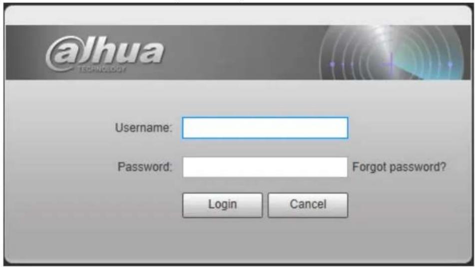
Appendix 1 Cybersecurity Recommendations
Cybersecurity is more than just a buzzword: it's something that pertains to every device that is connected to the internet. IP video surveillance is not immune to cyber risks, but taking basic steps toward protecting and strengthening networks and networked appliances will make them less susceptible to attacks. Below are some tips and recommendations on how to create a more secured security system.
Mandatory actions to be taken for basic device network security:
1. Use Strong Passwords
Please refer to the following suggestions to set passwords:
● The length should not be less than 8 characters;
- Include at least two types of characters; character types include upper and lower case letters, numbers and symbols;
- Do not contain the account name or the account name in reverse order;
- Do not use continuous characters, such as 123, abc, etc.;
- Do not use overlapped characters, such as 111, aaa, etc.;
2. Update Firmware and Client Software in Time
- According to the standard procedure in Tech-industry, we recommend to keep your device (such as NVR, DVR, IP camera, etc.) firmware up-to-date to ensure the system is equipped with the latest security patches and fixes. When the device is connected to the public network, it is recommended to enable the "auto-check for updates" function to obtain timely information of firmware updates released by the manufacturer.
- We suggest that you download and use the latest version of client software.
"Nice to have" recommendations to improve your device network security:
1. Physical Protection
We suggest that you perform physical protection to device, especially storage devices. For example, place the device in a special computer room and cabinet, and implement well-done access control permission and key management to prevent unauthorized personnel from carrying out physical contacts such as damaging hardware, unauthorized connection of removable device (such as USB flash disk, serial port), etc.
2. Change Passwords Regularly
We suggest that you change passwords regularly to reduce the risk of being guessed or cracked.
3. Set and Update Passwords Reset Information Timely
The device supports password reset function. Please set up related information for password reset in time, including the end user's mailbox and password protection questions. If the information changes, please modify it in time. When setting password protection questions, it is suggested not to use those that can be easily guessed.
4. Enable Account Lock
The account lock feature is enabled by default, and we recommend you to keep it on to guarantee the account security. If an attacker attempts to log in with the wrong password several times, the corresponding account and the source IP address will be locked.
5. Change Default HTTP and Other Service Ports
We suggest you to change default HTTP and other service ports into any set of numbers between 1024\~65535, reducing the risk of outsiders being able to guess which ports you are using.
6. Enable HTTPS
We suggest you to enable HTTPS, so that you visit Web service through a secure communication channel.
7. MAC Address Binding
We recommend you to bind the IP and MAC address of the gateway to the device, thus reducing the risk of ARP spoofing.
8. Assign Accounts and Privileges Reasonably
According to business and management requirements, reasonably add users and assign a minimum set of permissions to them.
9. Disable Unnecessary Services and Choose Secure Modes
If not needed, it is recommended to turn off some services such as SNMP, SMTP, UPnP, etc., to reduce risks.
If necessary, it is highly recommended that you use safe modes, including but not limited to the following services:
- SNMP: Choose SNMP v3, and set up strong encryption passwords and authentication passwords.
- SMTP: Choose TLS to access mailbox server.
- FTP: Choose SFTP, and set up strong passwords.
- AP hotspot: Choose WPA2-PSK encryption mode, and set up strong passwords.
10. Audio and Video Encrypted Transmission
If your audio and video data contents are very important or sensitive, we recommend that you use encrypted transmission function, to reduce the risk of audio and video data being stolen during transmission.
Reminder: encrypted transmission will cause some loss in transmission efficiency.
11. Secure Auditing
- Check online users: we suggest that you check online users regularly to see if the device is logged in without authorization.
- Check device log: By viewing the logs, you can know the IP addresses that were used to log in to your devices and their key operations.
12. Network Log
Due to the limited storage capacity of the device, the stored log is limited. If you need to save the log for a long time, it is recommended that you enable the network log function to ensure that the critical logs are synchronized to the network log server for tracing.
13. Construct a Safe Network Environment
In order to better ensure the safety of device and reduce potential cyber risks, we recommend:
- Disable the port mapping function of the router to avoid direct access to the intranet devices from external network.
-
The network should be partitioned and isolated according to the actual network needs. If there are no communication requirements between two sub networks, it is suggested to use VLAN, network GAP and other technologies to partition the network, so as to achieve the network isolation effect.
-
Establish the 802.1x access authentication system to reduce the risk of unauthorized access to private networks.
- Enable IP/MAC address filtering function to limit the range of hosts allowed to access the device.
ENABLING A SAFER SOCIETY AND SMARTER LIVING

- Foreword
- General
- Models
- Revision History
- About the Manual
- Important Safeguards and Warnings
- Operation Requirements
- Electrical Safety
- Table of Contents
- Foreword.... I
- Important Safeguards and Warnings.... III
- Network Configuration .... 1
- Live View 9
- Playback.... 14
- Setting....21
- Network Configuration
- Network Connection 1.1
- Logging in to Web Client
- Device Initialization
- Step 4 Click Save.
- Step 6 Read on-screen notifications, select P2P check box as needed, and then click Next.
- Step 7 Read on-screen notifications, select Auto-check for updates check box as needed, and then click Next.
- First-time Login
- Forgetting Password
- Step 2 Click Forgot password?
- Step 3 Click OK.
- Step 6 Click Save.
- Live View
- Encoding Configuration
- Video Tool
- Video Window Adjustment
- System Menu 2.4
- Function Options 2.5
- Device List 2.6
- PTZ Control 2.7
- Playback
- Video Playback 3.1
- Playing Video
- Record Types
- Auxiliary Functions
- Record Files
- Clipping Records
- Time Format of the Time Bar
- Snapshot Playback
- Playing Snapshots
- Snapshot Files
- Snapshot Types
- Setting
- Radar 4.1
- Video
- Video Stream
- Snapshot
- Overlay
- PTZ Camera
- Linkage
- Importing a Map
- Radar Positioning
- Region Management
- 2) Click Save.
- Protection Zone Management
- IVS Setup
- Network
- TCP/IP
- Step 1 Select Setting > Network > TCP/IP.
- Step 2 Configure parameters. See Table 4-8.
- A demonstration of configuring IP address with ARP/Ping
- Port
- Step 2 Configure port parameters. See Table 4-10.
- PPPoE
- DDNS
- SMTP (Email)
- UPnP
- SNMP
- Step 2 Select SNMP version to enable SNMP.
- Step 3 Click Save.
- Step 4 View radar information.
- Bonjour
- Step 1 Select Setting > Network > Bonjour.
- Multicast
- 802.1x
- QoS
- Access Platform
- P2P
- ONVIF
- Event Management 4.3
- Alarm
- Abnormality
- SD Card
- Network
- Illegal Access
- Security Exception
- Scene Changing
- Storage 4.4
- Schedule
- Record Schedule
- Step 2 Set a record plan.
- Snapshot Schedule
- Holiday Schedule
- Destination
- Path
- Local
- FTP
- NAS
- Record Control
- System 4.5
- General
- Date & Time
- Account
- User
- Anonymous Login
- Adding a User
- Modifying a User
- Modifying the Password
- Deleting a User
- Group
- Adding a Group
- Modifying a Group
- Deleting a Group
- Onvif User
- Safety
- RTSP Authentication
- System Service
- HTTPS
- 11) Click Finish.
- 12) Click Yes.
- Firewall
- Step 1 Select Setting > System > Safety > Firewall.
- Default
- Import/Export
- Auto Maintain
- Upgrade
- Information 4.6
- Version
- Log
- Remote Log
- Online User
- Alarm
- Logging out
- Appendix 1 Cybersecurity Recommendations
- Mandatory actions to be taken for basic device network security:
- Use Strong Passwords
- Update Firmware and Client Software in Time
- "Nice to have" recommendations to improve your device network security:
- Physical Protection
- Change Passwords Regularly
- Set and Update Passwords Reset Information Timely
- Enable Account Lock
- Change Default HTTP and Other Service Ports
- Enable HTTPS
- MAC Address Binding
- Assign Accounts and Privileges Reasonably
- Disable Unnecessary Services and Choose Secure Modes
- Audio and Video Encrypted Transmission
- Secure Auditing
- Network Log
- Construct a Safe Network Environment
- ENABLING A SAFER SOCIETY AND SMARTER LIVING
Brand : Dahua Technology
Model : PFR4K-D450
Category : Motion detector