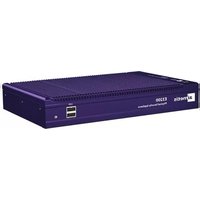
AIM-E3210 - Security Camera Aimetis - Free user manual and instructions
Find the device manual for free AIM-E3210 Aimetis in PDF.


| Product Type | Security Camera |
| Brand | Aimetis |
| Model | AIM-E3210 |
| Image Sensor | 1/2.7" Progressive Scan CMOS |
| Resolution | 2 MP (1920 x 1080) |
| Lens | 2.8 mm fixed lens |
| Night Vision | IR LEDs, up to 30 m |
| Pan/Tilt | No (fixed mount) |
| Connectivity | Ethernet (10/100 Base-T), PoE |
| Power | PoE (IEEE 802.3af) or DC 12V |
| Dimensions | 70 x 70 x 150 mm (approx.) |
| Weight | 400 g (approx.) |
| Weatherproof Rating | IP67 |
| Main Features | Motion detection, remote viewing, ONVIF compatible, H.265 compression |
| Care and Cleaning | Wipe the housing with a dry, soft cloth. Avoid solvents. |
| Safety | Use only certified PoE switches or power adapters. Do not expose to extreme temperatures. |
| Spare Parts and Repairability | No user-serviceable parts inside. Contact support for repairs. |
| General Information | Refer to the user manual for detailed installation and operation instructions. |
Frequently Asked Questions - AIM-E3210 Aimetis
User questions about AIM-E3210 Aimetis
0 question about this device. Answer the ones you know or ask your own.
Ask a new question about this device
Download the instructions for your Security Camera in PDF format for free! Find your manual AIM-E3210 - Aimetis and take your electronic device back in hand. On this page are published all the documents necessary for the use of your device. AIM-E3210 by Aimetis.
USER MANUAL AIM-E3210 Aimetis

natural_image
Purple E7000 Physical Security Appliance device with cooling fan and ports (no visible text or symbols beyond branding)Aimetis E-Series™
Physical Security Appliance Installation and User Guide
Table of Contents
Introduction 1
Setup Process ....2
Unpack the Box 3
E3200 Features .... 3
Front Panel E3200 4
Back Panel E3200 4
E7000 Features ....5
Front Panel E7000 6
Back Panel E7000 6
Connect the Aimetis Physical Security Appliance to the Network ......7
Using LAN1 or LAN1 & LAN2 7
Log in to Your Aimetis Physical Security Appliance 10
Log In 13
Computer Name 15
Network Settings 16
Running a DHCP Server 17
IP Address 17
DNS Servers 17
Date, Time & Time Zone 18
Time Synchronization 19
Password 20
Summary 21
Register 22
Install Symphony Client 23
Configure the Video Management Software (VMS) 25
Review Safety, Maintenance, and Support Information 26
Mounting the Aimetis Physical Security Appliance 27
(Optional) Position the Aimetis Physical Security Appliance on a Shelf .....27
(Optional) Wall Mount Instructions 27
Attaching the Wall Mounts to the E-Series Aimetis Physical Security Appliance ....27
Positioning the Aimetis Physical Security Appliance on a Wall 28
Using the Mounting Template to Position the Aimetis Physical Security Appliance ....28 Manually Positioning the Unit ....28
Appendix: Advanced Features 29
Symphony Services 29
Core Services 29
Optional Services 29
Restart System 30
Update System 31
Inputs/Outputs 32
Introduction
The Aimetis Physical Security Appliance combines a purpose-built hardware appliance with Aimetis Symphony™ video management and analytics software, creating a high performance intelligent video surveillance platform. Its robust fanless design and flexible installation options makes the appliance an ideal solution for space constrained environments and harsh environments.

flowchart
graph TD
    A["IP Camera"] --> B["Network Switch"]
    C["IP Camera"] --> B
    D["Aimetis Symphony Web Client"] --> B
    E["Aimetis Symphony Windows Client"] --> B
    F["Alarm"] --> G["Sensor / Relay"]
    H["Alarm Panel"] --> G
    B --> I["Aimetis E-Series"]
    G --> I
Figure 1: Hardware configuration example
Setup Process
- "Unpack the Box" on page 3
- "Connect the Aimetis Physical Security Appliance to the Network" on page 7
- "Log in to Your Aimetis Physical Security Appliance" on page 10
- "Install Symphony Client" on page 23
- "Configure the Video Management Software (VMS)" on page 25
- "Review Safety, Maintenance, and Support Information" on page 26
- "Mounting the Aimetis Physical Security Appliance" on page 27
- "Appendix: Advanced Features" on page 29
Table 1: Passwords
| Page Default Password | |
| PSALog In page | AimetisPSA(Can be changed onPasswordpage. See comment below.) |
| PSAPasswordpage Type in a new | password of your choice.The specified password is used by this Web Administration wizard and also used to restrict direct access to the appliance.This password does not apply to any user within the Aimetis Symphony software. |
| Symphony Client -RegisterSymphony Serverdialog box,Username, Passwordfields | Admin, Admin |
Step 1: Unpack the Box
Your Aimetis Physical Security Appliance package includes:
- Aimetis Physical Security Appliance
- CD with Installation and User Guide, Symphony Client software
- Metal wall mounts and screws for wall mounting of unit (optional)
- Feet for flat placement of unit (optional)
• Power adapter and power cord (E7000 Series only)
Note: Keep the packing material in case you need to return the appliance for service.
E3200 Features
Table 2: E3200 Series Specifications
| Model E3205POE E3210POE | ||
| CPU Dual Core Atom1.66Ghz | Dual Core Atom1.66Ghz | |
| RAM 2GB 2GB | ||
| OS Windows 7 embedded Windows 7 embedded | ||
| Storage 500GB 1TB | ||
| Video Management Software Symphony Standard Symphony Standard | ||
| Camera Licenses Included | 4 | 8 |
| Ethernet | 2xGbE | 2xGbE |
| USB | 4 | 4 |
| Integrated Inputs/Outputs | 4/4 4/4 | |
| Monitor Output | VGA | VGA |
| Extended storage | With NAS | With NAS |
| Video Analytics Ready | Yes | Yes |
| ONVIF | Yes | Yes |
| Network Protocols | DHCP, SMTP, SNMP | DHCP, SMTP, SNMP |
| Operating Temperature | 0 to 40 degrees Celsius | 0 to 40 degrees Celsius |
| Dimensions (mm) | 268W X 174D X 44H | 268W X 174D X 44H |
| Weight | 2.5KG | 2.5KG |
| Input Voltage | 12VDC/5 A Max or Power over Ethernet Plus (PoE+) IEEE 802.3at, max. 30 W | 12VDC/5 A Max or Power over Ethernet Plus (PoE+) IEEE 802.3at, max. 30 W |
Table 2: E3200 Series Specifications (Continued)
| Model E3205POE E3210POE | |
| Compliance CE, FCC, RoHs CE, FCC, RoHs | |
| Mounting Kit Wall mount included Wall mount included | |
| Warranty 2 year 2 year | |
| Ordering Information AIM-E3205POE AIM-E3210POE |
Front Panel E3200

Figure 2: Front panel - Aimetis logo on front panel of long side of unit
- USB (2 ports)
- On / Off switch
- SIM card slot
Back Panel E3200

Figure 3: Back panel
• VGA
• DIO
- USB (2 ports)
- Reset
• LAN2
• DC-IN
• LAN1 POE
Table 3: E7000 Specifications
| Model E7020 E7040 E7020A E7040A | ||||
| CPU | Intel®847E1.10 GHz | Cthrd@Celeron®847E1.10 GHz | Intel® CoreTMi7-2655LE2.2 GHz | Intel® CoreTMi7-2655LE2.2 GHz |
| RAM 4GB 4GB | 4GB 4GB | |||
| OS Windows 7 | embedded | Windows 7 embedded | Windows 7 embedded | Windows 7 embedded |
| Storage 2TB 4TB | 2TB 4TB | |||
| CameraLicensesIncluded | 8 Standard 16 Standard | 6 Standard | 2 Enterprise | 14 Standard2 Enterprise |
| Ethernet 2xGbE | 2xGbE | 2xGbE | 2xGbE | |
| USB | 4 | 4 | 4 | 4 |
| IntegratedInputs/Outputs | 8/8 | 8/8 | 8/8 | 8/8 |
| MonitorOutput | VGA | VGA | VGA | VGA |
| Extendedstorage | eSATA, NAS | eSATA, NAS | eSATA, NAS | eSATA, NAS |
| ONVIF | Yes | Yes | Yes | Yes |
| NetworkProtocols | DHCP, SMTP,SNMP | DHCP, SMTP,SNMP | DHCP, SMTP,SNMP | DHCP, SMTP,SNMP |
| OperatingTemperature | 0 to 40 degreesCelsius | 0 to 40 degreesCelsius | 0 to 40 degreesCelsius | 0 to 40 degreesCelsius |
| Dimensions(mm) | 277W X 190D X67H | 277W X 190D X67H | 277W X 190D X67H | 277W X 190D X67H |
| Weight | 4.3KG | 4.3KG | 4.3KG | 4.3KG |
| Input Voltage | 12V DC | 12V DC | 12V DC | 12V DC |
| Compliance | CE, FCC, RoHs | CE, FCC, RoHs | CE, FCC, RoHs | CE, FCC, RoHs |
| Mounting Kit | Wall (included)Rack (sold separately) | Wall (included)Rack (sold separately) | Wall (included)Rack (sold separately) | Wall (included)Rack (sold separately) |
| Warranty | 2 year | 2 year | 2 year | 2 year |
| OrderingInformation | AIM-E7020 AIM-E7040 AIM-E7020A | AIM-7040A | ||
Front Panel E7000
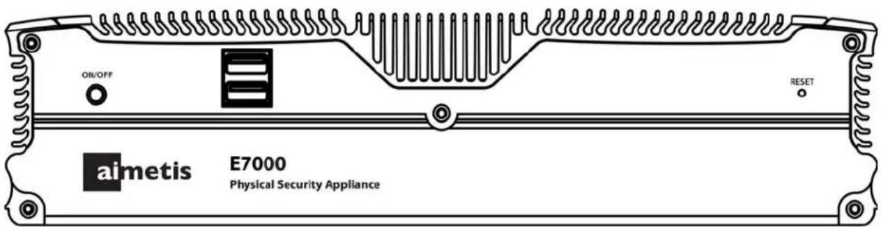
Figure 4: Front Panel E7000
• On / Off switch
- USB (2 ports)
- Reset
Back Panel E7000
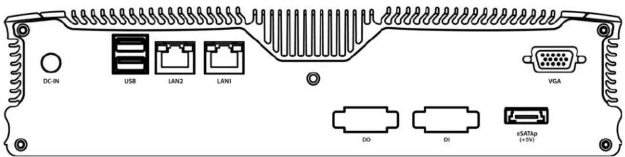
Figure 5: Back Panel E7000
- DC-IN
- USB (2 ports)
• LAN2
• LAN1
• DO
• DI
• eSATAp (+5V)
• VGA
Step 2: Connect the Aimetis Physical Security Appliance to the Network
Note the following points:
-
This is a setup procedure to configure basic system settings such as a computer name, IP address, time and time zone. Video management settings will be configured by Symphony Client.
-
Initial setup does NOT require a monitor, keyboard or mouse to be attached to the appliance. The VGA port and DVI-D port (if equipped) are for troubleshooting only.
-
The appliance will be configured using your Web browser once connected to your network.
Using LAN1 or LAN1 & LAN2
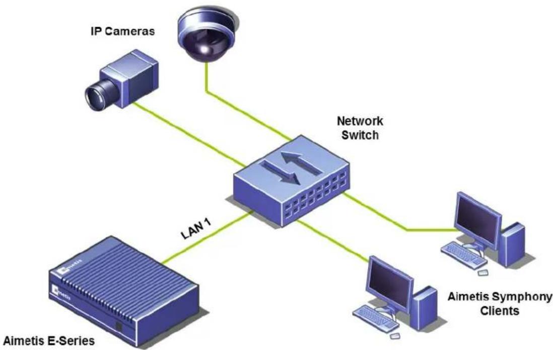
The appliance may be connected to a single network containing IP cameras and client computers. You may use either the LAN1 or the LAN2 ports on the back panel. Each port has a different default configuration. For convenience this guide will assume LAN1 is used.
flowchart
graph TD
    A["Aimetis E-Series"] -->|LAN 1| B["Network Switch"]
    C["IP Cameras"] --> B
    D["Aimetis Symphony Clients"] --> B
Figure 6: One network in use
The appliance may also be connected to two networks by using both the LAN1 and LAN2 ports on the back panel. Using two separate networks could be required if the video traffic must be isolated from the corporate network. The appliance can also act as a DHCP server for one of the two networks, typically the one connected to the video devices.
By isolating the video devices on a separate network, the video will only traverse the corporate network if a user wishes to see video. Otherwise no video will traverse the two networks. Figure 7 shows a typical network layout when two networks are in use. It shows cameras are on a separate network from clients.

flowchart
graph TD
    A["IP Cameras"] --> B["Network Switch B"]
    C["Almetis E-Series"] --> D["Network Switch A"]
    B -->|LAN 2| D
    D -->|LAN 1| C
    D --> E["Almetis Symphony Clients"]
Figure 7: Two networks in use
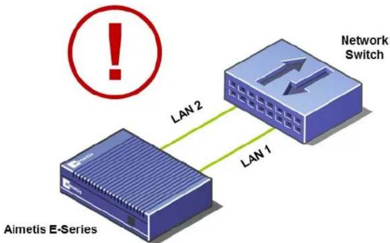
Never connect the LAN1 and LAN2 ports to the same network.
flowchart
graph LR
    A["Aimetis E-Series"] -->|LAN 1| B["Network Switch"]
    B -->|LAN 2| C["Warning Symbol"]
    style A fill:#f9f,stroke:#333
    style B fill:#bbf,stroke:#333
    style C fill:#fff,stroke:#333
Figure 8: Do NOT connect LAN1 and LAN2 to the same network
To perform initial setup:
-
Decide which network ports you want to use. The appliance comes configured as follows:
-
LAN1 is configured to obtain an IP address automatically using DHCP. If no DHCP server is available, the port will assign itself an IP address automatically using automatic private IP addressing. The IP address will be set to 169.254.x.y (where x.y is the device's unique identifier) with a subnet of 255.255.0.0.
• LAN2 is configured to a fixed IP address of 192.168.0.2. -
Connect the appliance to the network with a twisted-pair cat.5 or cat.6 cable using either LAN1 or LAN2 on the back panel.
Important: If using Power over Ethernet on E3200, the LAN1 port must be used to power device.
- Connect the power adaptor to the appliance (if applicable) and press the power button on the front panel. The power button will light up green and the hard disk activity indicator will flash as it boots.
- Connect your computer to the network. If using LAN1, ensure DHCP is enabled on your networking adapter. If using LAN2, ensure its network settings, specifically gateway and mask, will allow a connection to an IP address of 192.168.0.2.
Step 3: Log in to Your Aimetis Physical Security Appliance
The Administration Wizard is normally run only once.
To run the Administration Wizard:
- Load the CD into your computer. If the software does not start automatically use Windows Explorer or My Computer to browse the contents of the CD and double-click CDBrowser.exe.
- A window appears allowing you to select your preferred language.
- The CD Menu appears with the Start tab active.
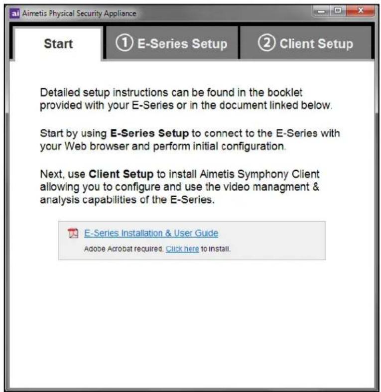
Figure 9: CD Menu - Start tab
- Read the information and then click the E-Series Setup tab.

Figure 10: CD Menu - E-Series Setup tab
- Click Find E-Series on Network. The Aimetis Physical Security Appliance Locator window opens and the locator automatically begins searching your network.
- The found Aimetis Physical Security Appliance devices will appear in a list. Click Connect to configure the device (Figure 11).

Figure 11: Locator page
- The Aimetis Physical Security Appliance Administration site will open in your Web browser. You are ready to log in and configure your appliance.
- Go to "Log In" on page 13.
Tip: Create a bookmark for the Aimetis Physical Security Appliance Administration site or make it a favorite. This will allow you to return the Web-based Aimetis Physical Security Appliance Administration site in the future without needing to use the software on the CD. The site can always be accessed using a Web address or URL such as: http://device:8080 where device will be either the IP address or Computer Name assigned to the appliance.
Log In
Enter the default password: AimetisPSA. The password is case sensitive.

Figure 12: Login page
The Welcome page appears. Press Next Page.

Figure 13: Welcome page
Computer Name
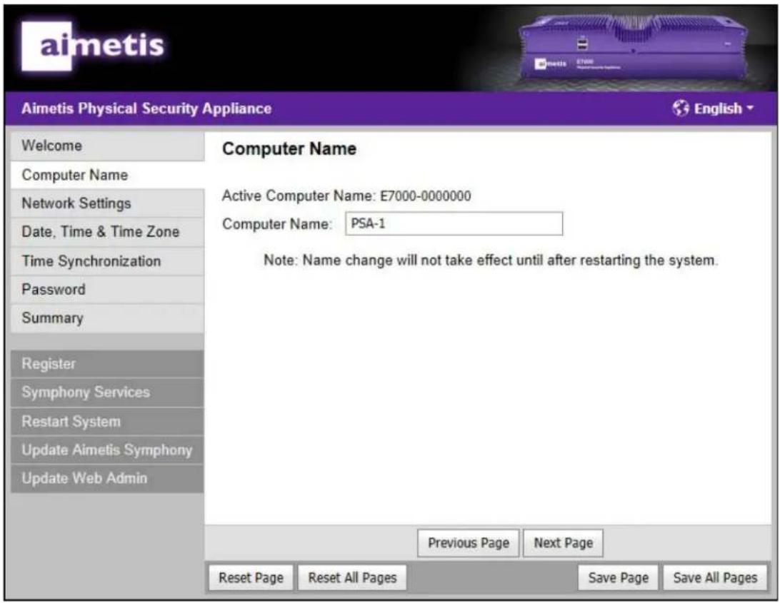
Figure 14: Computer Name page
-
(Optional) In the Computer Name field, enter a name to designate the appliance you are installing.
-
The name cannot be used by any other device on your network, including any other appliances.
-
You can keep the default name displayed in the Computer Name field.
-
Click Next Page.
Network Settings
By default the LAN1 port of the appliance is configured to use DHCP to obtain an IP address. When a DHCP server is unavailable, it will automatically select an IP Address in the range 169.254.X.X and a Subnet Mask of 255.255.0.0. The LAN2 port comes configured to use a fixed IP address of 192.168.0.2.
- If you want the appliance to act as a DHCP server, go to "Running a DHCP Server" on page 17.
- If the network does not have a DHCP server, or you want precise control over the IP address used, you may assign a specific IP address. Go to "IP Address" on page 17.
- If the network does not have a DHCP server, or you want precise control over the DNS servers used, you may assign specific DNS servers. Go to "DNS Servers" on page 17.

Figure 15: Network Connection page
Running a DHCP Server
The appliance can act as a DHCP server. You can configure a DHCP server on either network port of the appliance, but not both.
To run a DHCP server on a port:
- From the Mode drop-down list, select Run a DHCP Server.
- Optionally, specify the start address for the range of IP addresses the DHCP server will use in the IP Address Range Start field.
Note: The IP Address Range Start field must be set to an IP address ending in one. This IP address will also become the address of appliance. The range will extend from .1 to .255 creating a pool of 255 IP addresses.
IP Address
To assign a specific IP address:
- From the Mode drop-down list, select Assign a specific IP Address.
- Enter the address in the IP Address field.
- Enter a value in the Subnet Mask field.
Warning : If you change the IP address of the port your computer is connected to and the subnet no longer matches your computer, you will lose access to the appliance after saving your changes.
DNS Servers
A DNS server may be used by the Aimetis Symphony Server installed on the appliance. A DNS server is necessary only when the appliance is connected to the Internet and a specific setting within Symphony uses a domain name. A common use of a domain name would be to identify an email server. Aimetis Symphony can use an email server to send an email as an alarm action.
To assign specific DNS servers:
- If Mode is set to Obtain an IP address automatically using DHCP, clear the Obtain an IP address automatically using DHCP check box.
- Enter a DNS server address in the Preferred DNS Server field.
- (Optional) Enter a DNS server address in the Alternate DNS Server field.
- Click Next Page.
For more information on using one or both network adapters, see "Using LAN1 or LAN1 & LAN2" in "Connect the Aimetis Physical Security Appliance to the Network" on page 7.
Date, Time & Time Zone

Figure 16: Date, Time & Time Zone page
- Select the local time zone.
- Enter or modify the current date and time.
- Click Next Page.
If this appliance is connected to the Internet, you may use the next screen of this administration wizard to automatically update the date and time from the Internet.
Time Synchronization

Figure 17: Time Synchronization page
If the appliance is connected to the Internet, it will automatically update its date and time from an Internet time server.
- Enable (or disable) time synchronization by selecting (or clearing) the Enable Time Synchronization check box.
- If time synchronization is enabled, select a time server from the Time Server drop-down list (or use the default selection).
- Time synchronization will not occur immediately. Its schedule is determined automatically based on many factors. To immediately update the date and time, click Synchronize Time Now.
- Click Next Page.
Password

Figure 18: Password page
- To protect your Aimetis Physical Security Appliance from unauthorized access, it is recommended that you change the password from the default one provided by Aimetis.
- Make sure to record the password you select somewhere in case it is ever forgotten.
- Click Next Page.
Summary

Figure 19: Summary page
Your changes are ready to be applied.
- Review the summary of the changes you have made.
-
Do one of the following:
-
If you did not change anything, initial setup is now complete.
- If you have not changed the Computer Name, click Save All Changes. Your changes will be applied immediately and initial setup will be complete.
- If you have changed the Computer Name, the system must be restarted.
a. Click Save All Changes & Restart System.
b. Allow several minutes for the system to restart.
c. Refresh the Web page.
d. Log in to the Administration site again if requested.
e. Initial setup is now complete.
- In the left menu bar, click Register to continue registering your appliance.
Register
Registration may be completed at a later time.

Figure 20: Register page
To register the E-Series:
-
An Internet connection is required:
-
If you do not have an Internet connection on your computer:
a. Write down the registration key displayed in the Register page.
b. Go to the Aimetis Web site to register from another computer: http://www.aimetis.com/RegisterPSA
- If you have an Internet connection:
a. Click the Register Now link.
b. Follow the instructions on the Registration page.
-
Close your browser.
-
Go to "Install Symphony Client" on page 23.
Step 4: Install Symphony Client
Important: You must install Symphony Client on all your client PCs
To install Aimetis Symphony Client software:
- Load the CD into your computer. If the software does not start automatically use Windows Explorer or My Computer to browse the contents of the CD and double-click CDBrowser.exe.
- A window appears allowing you to select your preferred language.
- The CD Menu appears. Click the Client Setup tab.
- Click the Install Aimetis Symphony Client link.
- You do not need to manually uninstall previous versions

Figure 21: CD Menu - Client Setup tab
- Any required components missing on your machine are listed in the InstallShield Wizard dialog box. To install missing components, click Install.
- After reviewing the license and warranty information in the License Agreement screen, click I accept the terms of the license agreement.
-
Click Next.
-
(Optional) If you want to change the installation location of Aimetis, click the Change button. You are not required to change this value.
- In tChange Installation Folder screen, enter the folder path in the Folder name field and click OK. The new destination is displayed next to the folder icon. (You can use the folder navigation in the Look in portion of the screen to navigate to the desired location.)
-
Click Next. The Ready to Install the Program Screen appears.
-
Review the data in the Current Settings area. If this information is correct, click Install to proceed with the installation.
- To complete the installation, click Finish. (The Launch the program check box is selected by default. This allows the Aimetis to open automatically when the installation is complete.)
- Go to "Configure the Video Management Software (VMS)" on page 25.
Step 5: Configure the Video Management Software (VMS)
To connect to Aimetis Symphony Server:
- Click the drop-down arrow in the Address field of the Add Symphony Server Connection dialog box. A list of possible servers appears. Select the IP address of the appliance.

Figure 22: Add Symphony Server Connection
- In the Name field, enter a name to identify the server in Symphony Client.
- In the User field, enter "Admin" and in the Password field enter, "Admin" and click OK.
- After you have successfully connected to the device with Symphony Client, refer to the Symphony Client User Guide for more information.
Step 6: Review Safety, Maintenance, and Support Information
Table 4: Safety, Maintenance, and Support
| Item Instruction | |
| Power source Input voltage | - 12VDC/5 A maximum. Plug the appliance into an outlet protected from power surges.Power over Ethernet Plus (PoE+) IEEE 802.3at, max. 30 W (E3200 only) |
| Heat Place the appliance | away from heat sources such as radiators, stoves, or other heat producing appliances. |
| Water/moisture | Do not use the appliance near water. For example, if the appliance is placed on the floor and the floor is mopped occasionally with water, this will damage the appliance. Do not spill any liquid on the unit. Also, when moving the appliance from rooms with considerable temperature changes, do not immediately plug in the unit. Let the appliance adjust to the temperature change for at least two hours. |
| Cleaning Unplug the | appliance before cleaning. Do not use any chemical cleaners. A micro fibre cloth is best for wiping the unit. |
| Damage/Hardware failure/Missing parts/Servicing | In the event of a hardware failure, contact Aimetis support(www.aimetis.com/support) to obtain a Return Material Authorization(RMA) number. The replacement unit may be refurbished, or substituted with similar products at the option of Aimetis. Aimetis cannot guarantee new replacement units shipped against RMAs. |
| Warranty Obtain your formal Warranty statement, including the warranties and license agreements applicable to AIMETIS hardware and software atwww.aimetis.com/PSA. | |
Step 7: Mounting the Aimetis Physical Security Appliance
- “(Optional) Position the Aimetis Physical Security Appliance on a Shelf”
• “(Optional) Wall Mount Instructions”
(Optional) Position the Aimetis Physical Security Appliance on a Shelf
If the appliance is positioned on a flat surface, install the 4 rubber feet included with the device.
- Screw the rubber feet into the 4 holes on the bottom of the device.
(Optional) Wall Mount Instructions
You can place the appliance flat on a shelf, but wall mounts are supplied for wall mounting, if necessary.
The Aimetis Physical Security Appliance package includes a box with:
- 2 metal wall mounts
- 4 small screws with integrated spring washer and flat washer to hold the metal wall mounts to the appliance
- 4 screws and 4 plastic screw anchor/wall plugs appropriate for drywall or plaster. If you are installing the appliance onto a wood or concrete wall, you must supply your own material-appropriate screws and anchors.
Required:
• Phillips screw driver
- Power drill
- Drill bit a little smaller than the closed end of the plastic anchor (or the same size for metal anchors)
Attaching the Wall Mounts to the E-Series Aimetis Physical Security Appliance
To attach the wall mounts to the appliance:
- With the unit flat on a desk, turn it upside down so that the Aimetis logo is not visible.
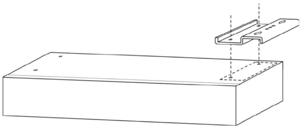
- Place the metal wall mount with the two-hole side, flush with the appliance. (The side with 3 holes and 2 large slotted holes will be used to attach the unit to the wall.)
natural_image
Technical line drawing of a rectangular frame with a U-shaped metal bracket and mounting holes, shown with dashed alignment lines (no text or symbols)Figure 23: Position metal wall mount on bottom of E-Series
- Using the small screws with the integrated spring washer and flat washer, fasten the wall mounts to the appliance.
- Flip the unit over so that the Aimetis logo is now visible. Note that bar with the slotted screw holes will sit flush against a wall.
Positioning the Aimetis Physical Security Appliance on a Wall
When the unit is vertically mounted, you must ensure that all ports are either at the bottom or at the top of the unit. This depends on how you want to connect cables from the appliance to your cameras and network. Decide which ports you want to access from the front panel or the back panel of the unit.

Figure 24: Aimetis logo on top of unit
You can position the screws holding the appliance two ways:
- "Using the Mounting Template to Position the Aimetis Physical Security Appliance"
- "Manually Positioning the Unit"
Using the Mounting Template to Position the Aimetis Physical Security Appliance
- Place the paper template provided in your package against the wall on which you want to install the appliance.
- Using a drill bit a little smaller than the closed end of the plastic anchor (use the same size for metal anchors), drill a hole through the center of each of the four holes marked on the template. Drill only as deep as the anchor.
- Hammer the anchor into the wall.
- Using a hand Phillips screw driver or your power drill, install the screw loosely.
- Slip the slotted holes of the appliance over the screws. Position and tighten the screws.
Manually Positioning the Unit
- Position the Aimetis Physical Security Appliance on the wall, and using a pencil, mark the slotted hole placement.
- Using a drill bit a little smaller than the closed end of the plastic anchor (use the same size for metal anchors), drill a hole through the center of your mark. Drill only as deep as the anchor.
- Hammer the anchor into the wall.
- Using a hand Phillips screw driver or your power drill, install the screw loosely.
- Test the position of the appliance by slipping one of the slotted holes over the screw.
- Check your pencil marks. If necessary, remark all the other holes, and install the other anchors and screws.
Appendix: Advanced Features
Symphony Services
This is an advanced feature. Use under guidance from Aimetis.
The Aimetis Physical Security Appliance uses Aimetis Symphony software, which also runs Windows services. This screen displays the status of various Aimetis Symphony services. All services listed under Core Services must be running for your appliance to work properly.
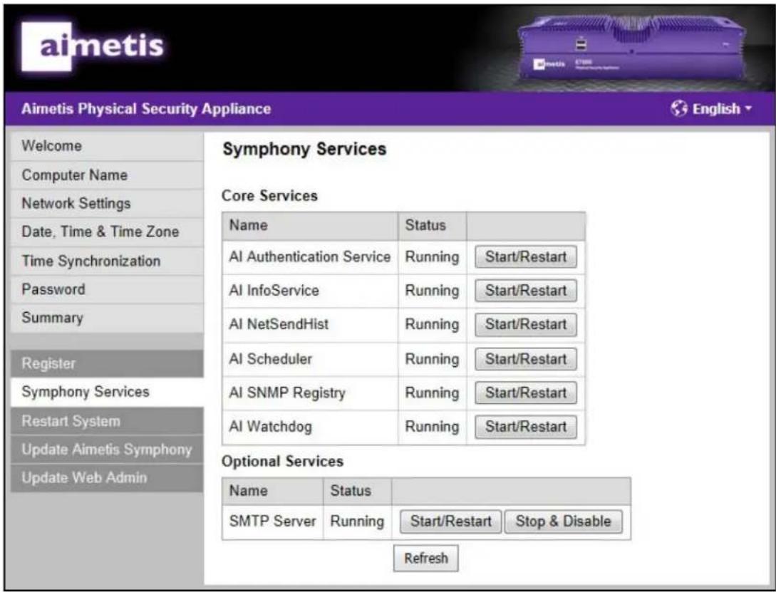
Figure 25: Symphony Services page
Core Services
If a service listed in the Name column is not Running, click the Start/Restart link associated with that service.
Optional Services
These services may be disabled by clicking Stop & Disable. For example, if you configure Aimetis Symphony Server to use a corporate SMTP mail server, you may disable SMTP Server on the appliance.
Note: Clicking the Refresh button updates the statuses of all services.
Restart System
This is an advanced feature. Use under guidance from Aimetis.
Clicking the Restart Now button restarts the Aimetis Physical Security Appliance only and not your computer.

Figure 26: Restart System page
Update System
This is an advanced feature. Use under guidance from Aimetis.
When an update is available from Aimetis that you require, you may update your Aimetis Physical Security Appliance.
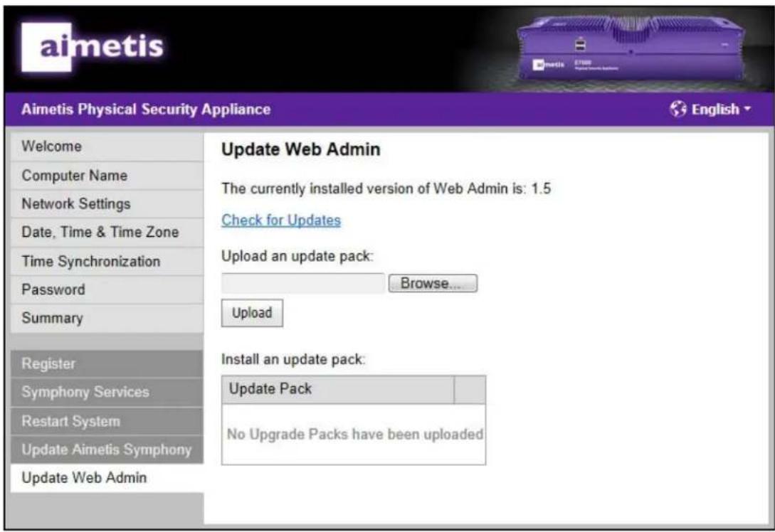
Figure 27: Upload an update pack page
- Make sure your computer is connected to the Internet and the Aimetis Physical Security Appliance.
- Go to the Aimetis Xnet and download an update pack. Save the pack in a convenient location on your computer.
- Click Browse to select the update pack saved on your computer.
- Click Upload. The filename is displayed in the Pack column.
- Click the Install link next to the Update Pack you uploaded. Follow any on-screen instructions.
Inputs/Outputs
The pin assignments should be used when connecting input and output devices to the Aimetis Physical Security Appliance. For more information about integrating I/O devices with Aimetis Symphony, refer to the Aimetis Symphony Analytics and Rules Guide.
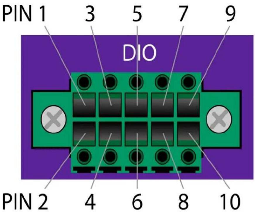
Figure 28: DIO on E3200 Series
| Input | ||||
| I1 | I2 | I3 | I4 | Ground |
| Pin1 | Pin3 | Pin5 | Pin7 | Pin9 |
| Pin2 | Pin4 | Pin6 | Pin8 | Pin10 |
| O1 | O2 | O3 | O4 | Ground |
| Output | ||||

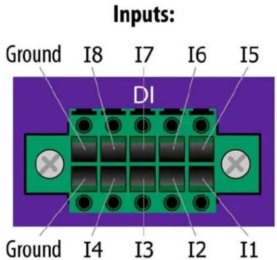
Figure 29: DIO on E7000 Series
Table 5: Connection Information
| Digital Inputs | |
| To activate: Connect to ground | |
| To deactivate: Leave floating or | unconnected |
| Notes: Source current when active: <1 mA | |
| Digital Outputs | |
| When activated: Connected to ground | |
| When deactivated: Left floating | |
| Notes: Max. sink current: 100 mAMax. voltage: 5V DC | |
Copyright © 2012 Aimetis Inc. All rights reserved.
This guide is for informational purposes only.
AIMETIS MAKES NO WARRANTIES, EXPRESS, IMPLIED OR STATUTORY, AS TO THE INFORMATION IN THIS DOCUMENT.
Complying with all applicable copyright laws is the responsibility of the user. Without limiting the rights under copyright, no part of this document may be reproduced, stored in or introduced into a retrieval system, or transmitted in any form or by any means (electronic, mechanical, photocopying, recording, or otherwise), or for any purpose, without the express written permission of Aimetis Corp.
Aimetis may have patents, patent applications, trademarks, copyrights, or other intellectual property rights covering subject matter in this document. Except as expressly provided in any written license agreement from Aimetis, the furnishing of this document does not give you any license to these patents, trademarks, copyrights, or other intellectual property.
Aimetis and Aimetis Symphony are either registered trademarks or trademarks of Aimetis Corp. in the United States and/or other countries.
- Aimetis E-Series™
- Physical Security Appliance Installation and User Guide
- Table of Contents
- Introduction
- Setup Process
- Step 1: Unpack the Box
- E3200 Features
- Front Panel E3200
- Back Panel E3200
- Front Panel E7000
- Back Panel E7000
- Step 2: Connect the Aimetis Physical Security Appliance to the Network
- Using LAN1 or LAN1 & LAN2
- To perform initial setup:
- Step 3: Log in to Your Aimetis Physical Security Appliance
- To run the Administration Wizard:
- Log In
- Computer Name
- Network Settings
- Running a DHCP Server
- To run a DHCP server on a port:
- IP Address
- To assign a specific IP address:
- DNS Servers
- To assign specific DNS servers:
- Date, Time & Time Zone
- Time Synchronization
- Password
- Summary
- Register
- To register the E-Series:
- Step 4: Install Symphony Client
- To install Aimetis Symphony Client software:
- Step 5: Configure the Video Management Software (VMS)
- To connect to Aimetis Symphony Server:
- Step 6: Review Safety, Maintenance, and Support Information
- Step 7: Mounting the Aimetis Physical Security Appliance
- (Optional) Position the Aimetis Physical Security Appliance on a Shelf
- (Optional) Wall Mount Instructions
- Attaching the Wall Mounts to the E-Series Aimetis Physical Security Appliance
- Positioning the Aimetis Physical Security Appliance on a Wall
- Using the Mounting Template to Position the Aimetis Physical Security Appliance
- Manually Positioning the Unit
- Appendix: Advanced Features
- Symphony Services
- Core Services
- Optional Services
- Restart System
- Update System
- Inputs/Outputs
Brand : Aimetis
Model : AIM-E3210
Category : Security Camera