
RM-2443WS-3G - Loudspeaker Wohler - Free user manual and instructions
Find the device manual for free RM-2443WS-3G Wohler in PDF.

| Product Type | Active Loudspeaker (Rackmount Monitor) |
| Model | RM-2443WS-3G |
| Driver Configuration | 2-way: 2x 4-inch woofers, 1x 3-inch tweeter |
| Dimensions (H x W x D) | 1.75 x 19 x 8 inches (44 x 483 x 203 mm) |
| Weight | 10 lbs (4.5 kg) |
| Power Output | 50W RMS (total) |
| Frequency Response | 60 Hz – 20 kHz |
| Inputs | Balanced XLR, unbalanced RCA, 3G-SDI loop-through |
| Controls | Volume, power switch, EQ presets (selectable) |
| Mounting | 19-inch rackmount (1U), rear support brackets included |
| Shielding | Magnetic shielding for close proximity to CRTs |
| Protection | Overload, short circuit, thermal protection |
| Operating Temperature | 0°C to 40°C (32°F to 104°F) |
| Cleaning | Wipe with a soft, dry cloth. Do not use liquid cleaners. |
| Safety | Do not expose to rain or moisture. Use rack screws securely. |
| Spare Parts & Repairability | Contact Wohler customer service for genuine parts and service. |
| General Information | Professional broadcast monitor speaker; SDI audio de-embedding capability. |
Frequently Asked Questions - RM-2443WS-3G Wohler
User questions about RM-2443WS-3G Wohler
0 question about this device. Answer the ones you know or ask your own.
Ask a new question about this device
Download the instructions for your Loudspeaker in PDF format for free! Find your manual RM-2443WS-3G - Wohler and take your electronic device back in hand. On this page are published all the documents necessary for the use of your device. RM-2443WS-3G by Wohler.
USER MANUAL RM-2443WS-3G Wohler
© 2016 Wohler Technologies, Inc. All rights reserved.
This publication is protected by federal copyright law. No part of this publication may be copied or distributed, stored in a retrieval system, or translated into any human or computer language in any form or by any means electronic, mechanical, manual, magnetic, or otherwise, or disclosed to third parties without the express written permission of Wohler Technologies.
Reproduction
Licensed users and authorized distributors of Wohler Technologies, Inc. products may copy this document for use with Wohler Technologies., Inc. products provided that the copyright notice above is included in all reproductions.
Customer Support
Wohler Technologies, Inc. 31055 Huntwood Avenue
Hayward, CA 94544 www.wohler.com
Phone: 510-870-0810
FAX: 510-870-0811
US Toll Free: 1-888-596-4537 (1-888-5-WOHLER)
Web: www.wohler.com Sales: sales@wohler.com
Support: support@wohler.com
Disclaimers
Even though Wohler Technologies, Inc. has tested its equipment and software, and reviewed the documentation, Wohler Technologies, Inc. makes no warranty or representation, either express or implied, with respect to software, documentation, their quality, performance, merchantability, or fitness for a particular purpose.
In no event will Wohler Technologies, Inc. be liable for direct, indirect, special, incidental, or consequential damages resulting from any defect in the hardware, software, or its documentation, even if advised of the possibility of such damages.
Some states do not allow the exclusion or limitation for incidental or consequential damages, so the above exclusion or limitation may not apply to you.
Printing
This document looks best when printed on a color printer since some images may be indistinct when printed on a black and white printer.
All text strings underlined in this shade of blue are hyperlinks within this document.
Other Technologies and Products
Google Chrome is a registered trademark of Alphabet Inc. Microsoft Windows and Internet Explorer are registered trademarks of Microsoft Corporation. Evertz and MAGNUM are registered trademarks of Evertz Microsystems Ltd.
Last Update
November 5, 2016
Contents
User Guide 1
TABLE OF CONTENTS 3
Contents....3
CHAPTER 1: Installation....5
Introduction 5
Overview 5
Features 5
Safety 5
Instructions....5
Safety Symbols....6
Mounting....6
Heat Dissipation....6
Sympathetic Vibration....7
Mechanical Bracing 7
Electrical Interference 7
Power....7
Compliance 7
FCC....7
ICES-003 8
CHAPTER 2: Local Operation....9
Front Panel....9
On-Screen Display Features.... 10
Rear Panel.... 12
Rear Panel Connectors 13
Using the Quick Menu and the OSD Menus.... 14
Quick Menu 15
OSD Menus 15
OSD Menus 16
CHAPTER 3: Technical Info 23
CHAPTER 4: Using Network Control 26
Web Browser / Control Device.... 26
First Time- IP Assignments ...... 26
Status Page.... 27
Adjust Page 29
Video Display Page 30
Input Setup Page 30
Marker Page 31
Audio Page 32
Close Caption Page.... 33
Config Page.... 33
Color Temperature Page.... 34
Function Key Page 35
IMD Page 36
System Page 37
Introduction
Overview
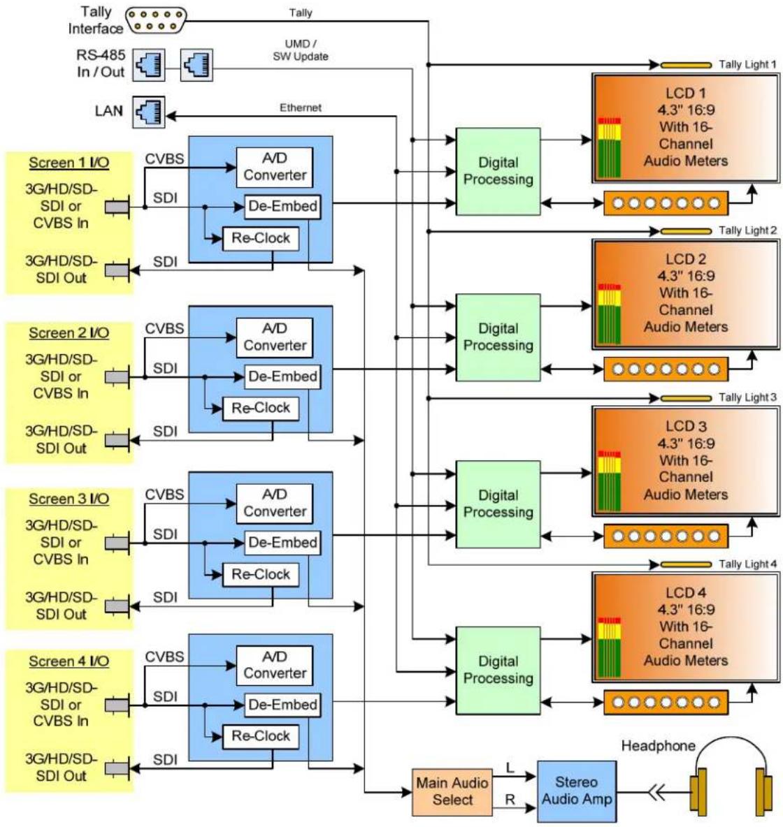
The 2RU rack-mounted RM-2443WS Series monitors set a new standard in LCD monitors for broadcast and professional video applications. They provide four 4.3", 800 x 400 resolution, 16:9 format, anti-glare IPS LCD screens. All video formats are scaled to fit on screen in the highest quality using fully digital processing, precision scaling and gamma correction to produce the best images possible.
Features
The RM-2443WS-3G2 and -3G audio/video monitors are designed for confidence monitoring of 3G/HD/SD-SDI digital video and CVBS composite analog video. Input signals are easily selected and displayed. Two to sixteen audio channels per screen may be selected for visual monitoring on bar graph style level meters. On screen markers, waveform, and vector displays can be enabled on this full-featured monitor. A headphone jack allows audible stereo monitoring of the left/right channels on all models. When mounted in a rack, they can tilt upwards or downwards for easy visibility.
Parameters are selected and adjusted using an On Screen Display (OSD) Menu. An RJ45 connector serves as the interface to the four tally lights on the front panel. Monitor settings can also be made with a web browser over Ethernet using the integral web server.
Safety
Instructions
- Read, keep, and follow all of these instructions; heed all warnings.
- Do not use this equipment near water.
- Use only a dry cloth to clean the equipment.
- Do not block any ventilation openings.
- Do not install near any heat source such as a radiator, heat register, amplifier, or stove.
- Do not attempt to plug the unit into a two-blade outlet (with only two prongs of equal width).
Important:
By design, this monitor will only plug into a three-prong outlet for your safety. If the plug does not fit into the outlet, contact an electrician to replace the obsolete outlet.
- Protect the power cord from being walked on or pinched, particularly at plug connection on the equipment and at the socket.
- Use only the attachments/accessories specified by the manufacturer.
- Unplug the equipment during lightning storms or when unused for long periods of time.
- Refer all servicing to qualified service personnel. Servicing will be required under all of the following conditions:
a. The equipment has been damaged in any way, such as when the power-supply cord or plug is damaged.
b. Liquid had been spilled or objects have fallen onto the equipment.
c. The equipment has been exposed to rain or moisture.
d. The equipment does not operate normally.
e. The equipment has been dropped.
Safety Symbols

The symbol to the left warns of electric shock hazard inside the unit. Disconnect the power cord before removing access panels when installing upgrades. Only qualified service personnel are to operate the equipment with covers removed, and are to exercise caution to avoid personal injury.
Mounting
The unit is designed for a standard 19" rack. Install it at eye level for best visual observation of the display screens or tilt it toward the user. Please adhere to the following clearances:
Table 1-1: Recommended Clearances
| Clearance | Surface |
| 24" | Front |
| 3" | Rear |
| 2" | Sides |
| 1.75" | Top and Bottom (if either radiates heat) |
| 0" | Top and Bottom (if no heat) |
Heat Dissipation
The ambient temperature inside the mounting enclosure should not exceed 40^ Celsius ( 104^ Fahrenheit). Adjacent devices can be rack mounted (or stacked) in
proximity to the unit if this temperature is not exceeded. Otherwise, allow a 1RU (1.75"/44.45mm) space above and below the unit for air circulation.
Important:
These monitors contain a fan to ventilate the heat generated by the audio amplifiers, video processing circuitry, and other components. The fan opening and other vents must not be blocked. The fan can be optioned to be always on, always off, or automatic. For long product life, it is recommended that the fan not be set to always off.
Sympathetic Vibration
Sympathetic vibration from other equipment (cables, etc.) in the rack may be serious enough to interfere with the unit's sound quality. If you experience sympathetic vibrations, use thin card stock, felt, foam, or weather-stripping between the vibrating surfaces. Tie loose cables securely with cable ties.
Mechanical Bracing
The 2RU chassis is securely attached to the front panel. In addition, the chassis has mounting tabs through which you attach it to the rack rail. This feature will reduce or eliminate rear bracing requirements in many mobile/portable applications. The weight of internal components is distributed fairly evenly around the unit.
Electrical Interference
Be careful to avoid mismatched cable types and other similar causes of undesired reflections in digital signal systems. If severe enough, such reflections can result in corruption of the digital data stream. As with any audio equipment, maximum immunity from electrical interference requires the use of shielded cable; however, satisfactory results can sometimes be obtained without it. The internal circuitry ground is connected to the chassis.
Power
The unit comes with an external power supply module which connects to an AC mains power source (35W, 100 to 240 VAC, ±10%, 50/60Hz) through the IEC connector provided on the rear panel of the unit.
When the mains plug or appliance coupler is used as the disconnect device, the disconnect device should remain operable.
Compliance
FCC
This equipment has been tested and found to comply with the limits for a Class A digital device, pursuant to part 15 of the FCC Rules. These limits are designed to provide reasonable protection against harmful interference when the equipment is operated in a commercial environment. This equipment generates, uses, and can
radiate radio frequency energy and, if not installed and used in accordance with the instruction manual, may cause harmful interference to radio communications. Operation of this equipment in a residential area is likely to cause harmful interference, in which case the user will be required to correct the interference at their own expense.
ICES-003
This Class A digital apparatus complies with Canadian ICES-003.
The RM-2443WS-3G2 and RM-2443WS-3G front and rear panels are described in this chapter.
Front Panel
Figure 2-1: Front Panel Layout

- Tally Lights: These tri-color (red/green/amber) lights are controlled through a RJ45 connector on the rear panel. For more information about the RJ45 connector, refer to Figure 2-5 and Table 2-1. When first connected to power, the Tally Lights glow amber until the unit is ready for operation.
- LCD Screen: The LCD screens display the audio meters, closed captioning, waveform/vector, menus, and OSD features over the video.
- Headphone Jack: Monitor the assigned left/right stereo audio channels with stereo headphones from this mini-stereo connector. Control the volume of the headphones using the Volume setting in the Quick Menu. Refer to the Using the Quick Menu and the OSD Menus section later in this chapter.
Note:
The left LCD must be turned on for audio to function from any screen, because the audio amplifiers are powered from the left LCD. So, if some of the screens will not be used, be certain that it is the left one is.
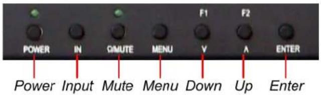
- Power: Each of the two Power buttons turn the associated LCD screen on and off; the LED glows green to indicate on. When the indicator above the power switch is green then the unit is receiving power. When the indicator is flashing, the unit is in stand-by mode.
-
Mute: The Mute button enables or disables audio monitoring via the headphone jack, and the light in the button will indicate the status of audio monitoring. When the light is on, the audio can be monitored, and when the light is off, it is mute.
-
Menu: Press this button to display the OSD Menu. Refer to the OSD Menus section of this chapter for operation and content of these menus.
- Enter: When the OSD Menu is displayed, pressing this button accepts selections in the menus and sub-menus. When the OSD Menu is not being displayed, pressing this button displays the Quick Menu, which cycles through volume and image controls. Refer to the Quick Menu section of this chapter.
- In: On the RM-2443WS-3G2, this button switches between the IN1 and IN2. Pressing the IN button will display a list of the possible inputs. It should then be pressed repeatedly to select the required input. On the RM-2443WS-3G, there is only one input per screen, so this button is not used.
- F1/ Down: The Down function is on the same button as the F1 function. When the OSD Menu or the Quick Menu are displayed, this button navigates down through the menu and sub-menu selections and can be used to adjust the settings. When the OSD Menu is not displayed, pressing this button initiates F1 function per its Function Key Menu setting. Refer to Table 2-13.
- F2/ Up: The Up function is on the same button as the F2 function. When the OSD Menu or the Quick Menu are displayed, this button navigates down through the menu and sub-menu selections and can be used to adjust the settings. When the OSD Menu is not displayed, pressing this button initiates F2 function per its Function Key Menu setting. Refer to Table 2-13.
On-Screen Display Features
Functions and parameters can be selected and adjusted using the On Screen Display (OSD) Menu. Refer to the OSD Menus section of this chapter.
Overlays can be added by the operator for Area & Safety Markers, Center Marker, and to display names as IMD (In Monitor Display) for identification.
Video effects such as Monochrome, Blue Only, Focus Assist, H/ V Delay and other features can be used to assist setup.
Overscan, Underscan and Native modes control scaling and size of the video.
Audio level meter displays, for up to sixteen channels, can be displayed vertically or horizontally, positioned at various corners of the display. They can show VU, PPM (PK) or both with assignable -20db to -18db reference levels.
Waveform (Y or Line) or Vectorscope can be small (as shown) or full screen sizes.
Closed Captions from CVBS Line 21 (CEA-608) can be decoded and text is displayed across the screen bottom. The 'CC' logo at screen top center indicates captions are present in the SDI stream.
The de-embedded Timecode from the HD/SD-SDI source displays on the lower part of the screen. Choose LTC, VITC or D-VITC types in the Display Menu.
Figure 2-2: Display Features
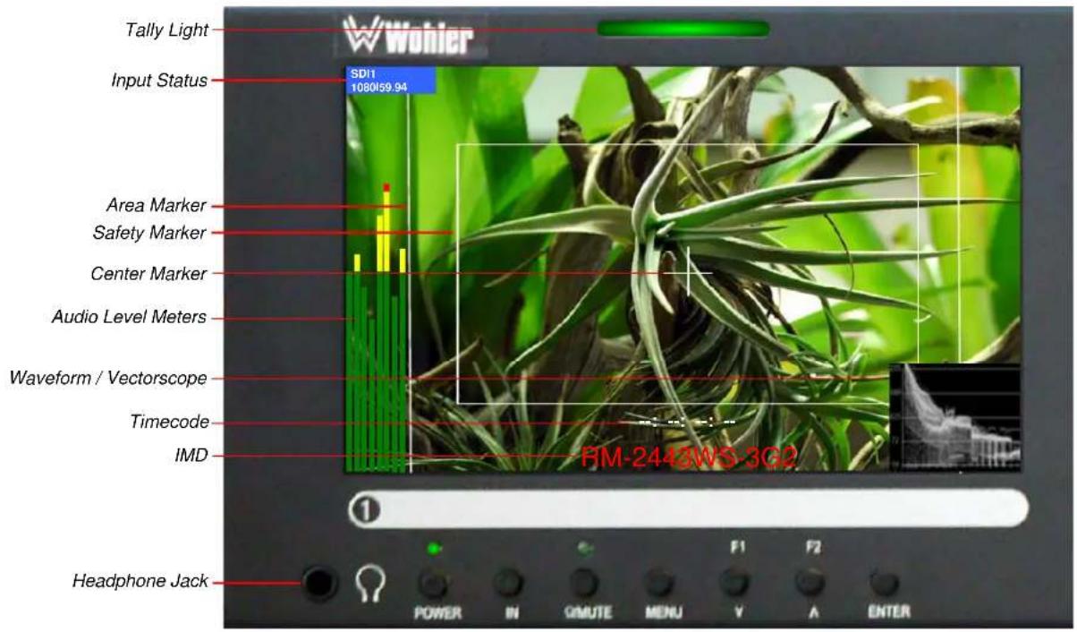
- Input Status: Displays the selected input and video parameters of vertical active line count, (i)nterlaced or (p)rogressive, and field/frame rate in Hz.
- Area Marker: Used to mark an alternate aspect ratio area of the image. You can set whether to display it, the display brightness, and the matte mode in the Marker Menu.
- Safety Marker: This is used to mark a percentage area, inside of the image, safe for titles to be located. You can set whether to display it, as well as its display mode, in the Marker Menu.
- Center marker: Cross hairs are displayed in the center of the screen, marking the center of the image. You can set whether to display it in the Marker Menu.
- IMD: The OSD Menu provides settings to customize the IMD (In Monitor Display) text area to show a static line of characters, numbers, and some symbols or to receive dynamic messages to display.
- Audio Level Meters: Levels for the audio channels are displayed on up to sixteen meters as left/right pairs. Up to sixteen meters can appear in various selectable positions on the screen. Refer to Table 2-7.
- Timecode: The de-embedded timecode from the HD/SD-SDI source displays on the lower part of the screen.
- Waveform/ Vectorscope: This can be displayed only for SDI signal. The waveform and vector of the input signal display are configurable in the Display Menu.
- AFD/ CC: SDI AFD (Active Format Description) and CC (Closed Caption) information will display at the top of the screen as icons.
Rear Panel
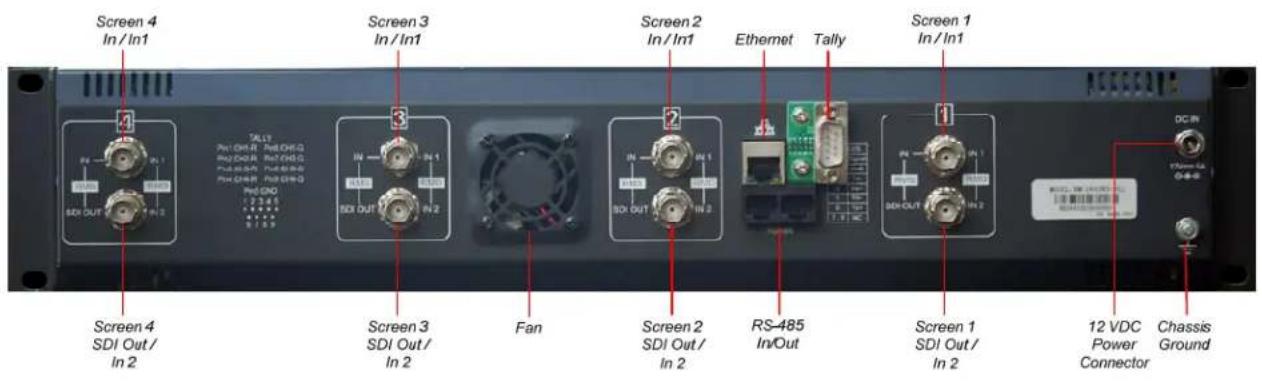
Figure 2-3: Rear Panel Layout
Note:
The left LCD must be turned on for audio to function from any screen, because the audio amplifiers are powered from the left LCD. So, if some of the screens will not be used, be certain that it is the left one is.
Important:

By design, the supplied AC mains power cord will only plug into a three-prong grounded outlet for your safety. If the plug does not fit into the outlet, contact an electrician to replace the obsolete outlet. The symbol to the left warns of electric shock hazard inside or outside the unit. Disconnect the power cord before removing access panels.
Important:
The monitor and power adapter have been tested as a combined apparatus to verify compliance with applicable safety and electromagnetic compliance standards. Use of another power adapter provided by the user may negate the compliance or not perform properly. Wohler Technologies cannot accept any responsibility for the outcome in such cases.
1. RM-2443WS-3G2:
a) In 1: This input connector accepts 3G/HD/SD-SDI video signals. It is compliant with SMPTE 424M, SMPTE 259M, SMPTE292M/ITU-R BT601. This BNC jack also accepts a CVBS signal and automatically detects it.
b) In 2: This second input connector accepts 3G/HD/SD-SDI video signals. It is compliant with SMPTE 424M, SMPTE 259M, SMPTE292M/ITU-R BT601. This BNC jack also accepts a CVBS signal and automatically detects it.
2. RM-2443WS-3G:
a) In: This input connector accepts 3G/HD/SD-SDI video signals. It is compliant with SMPTE 424M, SMPTE 259M, SMPTE292M/ITU-R BT601.
This BNC jack also accepts a CVBS signal and automatically detects it.
b) SDI Out: This connector provides a re-shaped and re-clocked duplicate of the SDI In 1 signal. This connection is compliant with SMPTE 424M, SMPTE 259M, SMPTE292M/ITU-R BT601. It is not an output when a CVBS signal is connected to In.
- Power Connector: The supplied 100 to 240VAC to 12VDC power supply plugs into this coax connector.
- Ethernet: The 10/100M Ethernet connector is used to connect with a computer to modify the display settings remotely. CAT5 network cables are recommended for medium distances. CAT6 twisted pair shielded cables are recommended for longer distances.
- Tally: This DB9M connector controls the tally lights on the front panel. Refer to Figure 2-4 below for the pinout and Table 2-1 for the terminal connections.
- RS-485 In/ Out: These RJ-45 jacks are used for dynamic Tally/IMD controls. Two jacks are provided for in & out daisy chain arrangements. They are wired identically. Refer to Figure 2-5 below for the pinout and Table 2-2 for terminal connections. These connections are also used for system software upgrades. Either CAT5 or CAT6 cables may be used for these jacks.
- Fan: The fan to ventilates the heat generated by the audio amplifiers, video processing circuitry, and other components. The fan opening and vents must not be blocked. Using the Config Menu, the fan can be optioned to be always on, always off, or automatic. Refer to Table 2.11. For long product life, it is recommended that the fan not be set to always off.
Rear Panel Connectors
The following figure and tables detail the connections of the Tally and RS-485 connectors on the rear panel. The tables are also silkscreened on the rear panel of the unit for your convenience.
Table 2-1: Tally Input Connections
| Pin | Tally Terminal Name |
| 1 | CH1-Red |
| 2 | CH2-Red |
| 3 | CH3-Red |
| 4 | CH4-Red |
| 5 | Ground |
| 6 | CH1-Green |
| 7 | CH2-Green |
| 8 | CH3-Green |
| 9 | CH4-Green |
To light a Tally in red, connect pin 1 (2, 3, or 4) to ground. To light a Tally in green, connect pin 6 (7, 8, or 9) to ground. To light a tally in amber, connect both pins 1 and 6 (2 and 7, 3 and 8, or 4 and 9) to ground.
Figure 2-4: Tally Input Pin-Out

Figure 2-5: RS-485 I/O Pin-Out
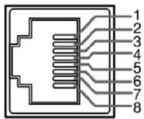
Table 2-2: RS-485 I/O Connections
| Pin | RS-485 Terminal Name |
| 1, 2 GND | |
| 3 | Tx- (pair A) |
| 4 Rx+ (pair B) | |
| 5 | Rx- (pair B) |
| 6 | Tx+ (pair A) |
| 7, 8 NC | |
Using the Quick Menu and the OSD Menus
In the following descriptions, refer to Figure 2-6 for the location of the control buttons.
Figure 2-6: Screen Control Buttons
Quick Menu
The Quick Menu provides quick access to a few commonly used features, as listed in Table 2-3. The Quick Menu appears as shown in Figure 2-7.
Figure 2-7: Quick Menu - Volume Setting

The following is a description of how to use the Quick Menu:
- Press the Enter button to display the Quick Menu and the first item that can be adjusted.
- Use the Up and Down buttons to change the value for the item displayed.
- Press the Enter button again to display the next adjustable item.
- The Quick Menu will time out with no button presses. Alternatively, you may press the Enter button repeatedly when finished until the menu disappears.
Table 2-3: Quick Menu
| Parameters | Default Value | Domain Range |
| VOLUME 16 0 - 31 | ||
| BRIGHTNESS | 50 | 0 - 100 |
| CONTRAST | 50 | 0 - 100 |
| CHROMA 50 0 - 100 |
OSD Menus
The OSD Menus allow you to adjust a wide variety of control parameters for the monitor. Refer to Table 2-4 through Table 2-14 for typical values and domain ranges. The following is a description of how to use the OSD Menus:
- Press the Menu button to display the Main Menu.
- Use the Up and Down buttons to navigate through the submenus.
- Press the Enter button to enter the parameter selections in the chosen submenu.
-
Use the Up or Down buttons to cycle through the submenu selections.
-
When the desired option is highlighted, press the Enter button to select it.
- Use the Up or Down buttons to adjust the parameter value up or down, make a selection, or turn a function on or off.
- Press the Enter button to accept your parameter change -or- press the Menu button to cancel your change.
- Press the Menu button to back out of any submenu, and finally to remove the OSD Menus from the screen.
OSD Menus
The following tables describe the information and settings available in the OSD Menu system. Use the instructions in the previous section to navigate the menus.
Table 2-4: Status Menu Structure
| Status | |||
| Parameters | Default Value | Domain Range Description | |
| INPUT | SD1 | SDI1SDI2 (RM-2443WS-3G2 only) | Display only for the value of each parameter. |
| FORMAT | NO SIGNAL | ||
| COLOR TEMP D65 | D32, D93, D65, D56, D50 | ||
| SCAN MODE NORMAL | NORMAL, OVER, UN | DER | |
| FAST MODE OFF | OFF or ON | ||
| MODEL | RM-2443WS-3G2 | ||
| SERIAL NUMBER - | |||
| IP ADDRESS 192.168 | .1.86 | ||
| COLOR VERSION - | |||
Table 2-5: Input Select Menu Structure
| Input Select | |||
| Parameters | Default Value | Domain Range | Description |
| IN1 | ON | One ON at a time, the other is OFF | Select which input will be monitored (RM-2443WS-3G2 only). |
| IN2 | OFF | ||
| NTSC SETUP 0 0, 7.5 | |||
| NTSC PHASE | 0 -50 to 50 | ||
Table 2-6: Marker Menu Structure
| Marker | |||
| Parameters | Default Value | Domain Range Description | |
| MARKER | OFF | ON or OFF | Turn all markers on or off. |
| AREA MARKER | OFF | If 16:9 aspect ratio: OFF, 4:3, 15:9, 14:9, 13:9, 1.85:1, 2.35:1If 4:3 aspect ratio: OFF, 16:9 | Set area marker size according to the aspect ratio. |
| CENTER MARKER | OFF | ON or | Turn center marker display on or off. |
| SAFETY MARKER | OFF | OFF, 80%, 85%, 88%, 90%, 93%, 95% | Set safety marker size according to the aspect ratio and scan mode. |
| MARKER LEVEL | 1 | 1: 50%, 2: 75%, 3: 100% | Set the luminance of all of the markers. |
| MARKER MAT | OFF | OFF, HALF (Background 50%) BLACK | Set the transparency of the area marker mat. |
| CROSS HATCH | OFF | ON or | Set whether to Enable the cross hatch display. |
Figure 2-8: Marker Mat Effect

natural_image
Close-up of a small dark object resting on a textured, rocky surface with no visible text or symbols.Marker Mat = OFF

natural_image
Close-up of a bird's head resting on a textured rock surface, with no visible text or symbolsMarker Mat = HALF

natural_image
Close-up of a bird perched on a textured rock surface, with no visible text or symbolsMarker Mat = BLACK
Table 2-7: Audio Menu Structure
| Audio | |||
| Parameters | Default Value | Domain Range Description | |
| SPEAK OUT L EBD | CH1 EBD CH1- | CH16 | Select the left headphone channel source. |
| SPEAK OUT R EBD | CH2 EBD CH1- | CH16 | Select the right headphone channel source. |
| AUDIO METER OFF | ON or OFF | Set whether to display the audio meters. | |
| METER SELECT CH | 1-2 | CH1-2, G1, G2, G3, G4, G1+G2, G1+G3, G1+G4, G2+G3, G2+G4, G3+G4, G1-G4 | Select channels or SDI groups to display on the meters. |
| METER DIRECTION | HORIZONTAL | VERTICAL, HORIZONTAL | Select whether you prefer vertical or horizontal meters. |
| METER POSITION | TOP | If METER DIRECTION is VERTICAL: LEFT, RIGHTIf METER DIRECTION is HORIZONTAL: BOTTOM, TOP | For vertical meters, select left or right. For horizontal meters, select bottom or top position. |
| METER DIS MODE | MODE1 | MODE1: meter onlyMODE2: meter & channel numbersMODE3: meter, channel numbers, and dB value | Select the appearance of the meters. |
| REF LEVEL -20DB | -18DB, -20DB | Set the meter reference level (green to yellow transition). | |
| OVER LEVEL -10DB | -2DB, -4DB, -6DB, -8DB, -10DB | Set the meter over level (yellow to red transition) | |
Table 2-8: Display Menu Structure
| Display | |||
| Parameters | Default Value | Domain Range | Description |
| STATUS DISPLAY | AUTO OFF, ON, | AUTO | Turn status display off, on, or automatic. If automatic, it will display for 15 seconds after each change. |
| AFD DISPLAY OFF | ON, OFF | Turn AFD display on only when status display is set to On or Auto, or else Off. | |
| WFM FORM SIZE | NORMAL FULL, | NORMAL | Set display of waveform to full screen size or normal PiP size. |
| WFM FORM TYPE | OFF | OFF WAVEFORM VECT75 VECT100 | Set the type of waveform / vector display. |
| LINE WAVE OFF | ON, OFF | Set whether to display the line wave. | |
| LINE WAVE NUMBER | --- Refer to Table 2-9. | Set the position of the waveform display. | |
| WAVEFORM OVER LIMIT | 50 50 to 100 | Set the over limit of the waveform. | |
| WAVEFORM UNDER LIMIT | 5 0 to 50 | Set the under limit of the waveform. | |
| TIME CODE OFF | OFF, D-VITC, LTC, VITC | Select the mode for the time code display or disable it. | |
Table 2-9: Line Wave Number vs. Input Signal
| Input Signal | Default Value | Domain Range |
| 576i50 310 23 - 6 | 23 | |
| 480i60 261 22 - 5 | 24 | |
| 720p | 386 26 - 745 | |
| 1080i50 | 560 21 - 1123 | |
| 1080i60/59.94 | ||
| 1080sf23/23.97 | ||
| 1035i60 | 557 41 - 1120 | |
| 1080p | 561 42 - 1121 |
Table 2-10: Closed Caption Menu Structure
| Closed Caption | |||
| Parameters | Default Value | Domain Range | Description |
| CLOSED CAPTION | CC1 | OFFCC1CC2CC3CC4TEXT1TEXT2TEXT3TEXT4 | Set type of CVBS caption to display, or turn it off. |
| SDI CC LOG OFF | ('CC' Logo) ON | or OFF | Set whether to display SDI closed caption information |
Table 2-11: Config Menu Structure
| Config | |||
| Parameters | Default Value | Domain Range | Description |
| FAST MODE OFF ON or OFF | Enable or disable fast mode. | ||
| FILM MODE DETECT | OFF ON or OFF | Enable or disable film mode detection. | |
| BACK LIGHT 15 0 | * to 30 | Set backlight timeout. | |
| AUTO STANDBY OFF | ON or OFF | Enable or disable auto standby mode. | |
| APERTURE 0 0 to 24 | Set picture sharpness. | ||
| LOCK NUMBER - Set lock number. | |||
| LANGUAGE | ENGLISH | ENGLISH, CHINESE | Set the menu language. |
| FAN | AUTO | AUTO, ON, OFF | AUTO will turn on the fan only when needed. ON will allow the fan to run all of the time. OFF will never allow the fan to run.* * |
* Note: Use caution when setting the Back light to a very low number. Setting the Back Light to 0 or a low number may make it impossible to see the menus to
correct the situation.
** Note: Setting the Fan to AUTO or ON can prolong the life of the product.
Table 2-12: Color Temp Menu Structure
| Color Temp | |||
| Parameters | Default Value | Domain Range Description | |
| COLOR TEMP D65 | D32, D50, D56, D65, D93, USER1, USER2 | Set the color temperature. | |
| RED GAIN | 128 0 to 256 | Set the gain for each color. | |
| GREEN GAIN | |||
| BLUE GAIN | |||
| RED BIAS | 0 -127 to +127 | Set the offset for each color. | |
| GREEN BIAS | |||
| BLUE BIAS | |||
| COPY FROM D93 | D32, D50, D56, D65, D93 | Copies this set of color parameters to USER. | |
| RESET Resets Gain and Offset to Factory Default | |||
| COLOR SPACE AUTO | OFF, EBU, SMPTE-C, ITU-709, AUTO | Select the color matrix. | |
Table 2-13: Function Key Menu Structure
| Function Key | |||
| Parameters | Default Value | Domain Range | Description |
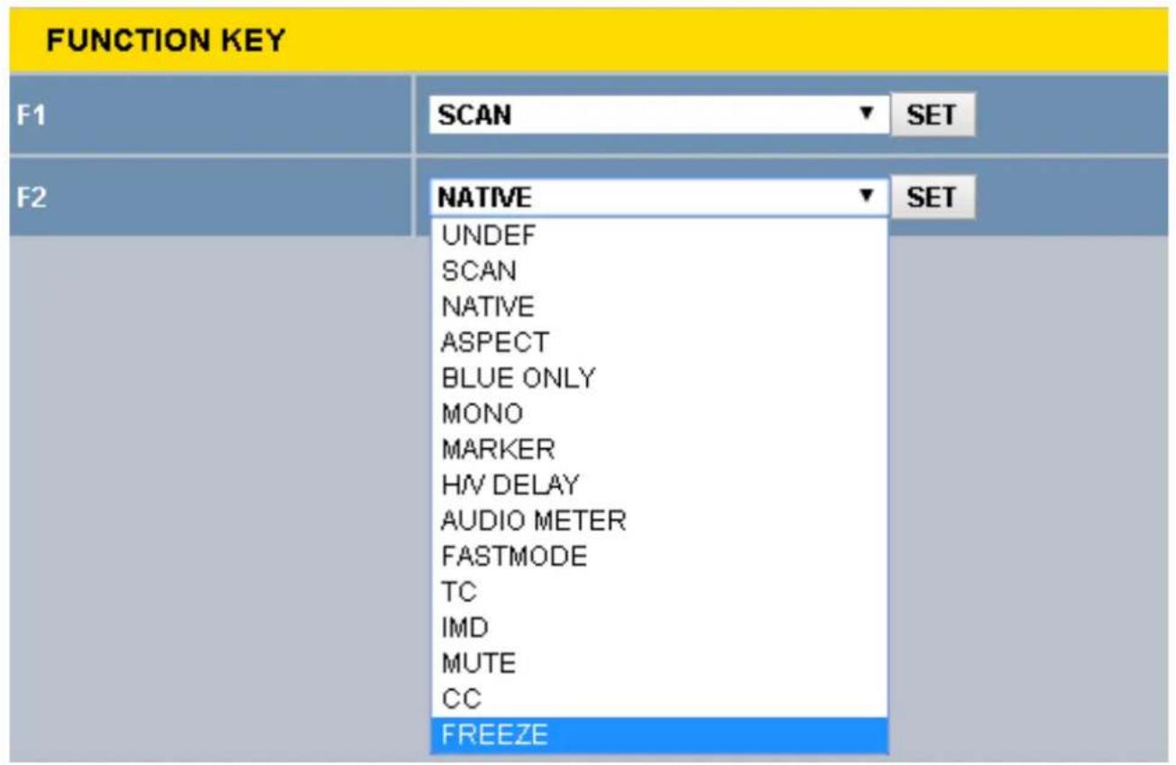
| F1 | SCAN | SCANNATIVEASPECTBLUE ONLYMONOMARKERH/V DELAYAUDIO METERFAST MODETCIMDMUTECCFREEZEUNDEF (none) | Set up the F1 Function key action. |
| F2 | NATIVE | Set up the F2 Function key action. | |
Table 2-14: IMD Menu Structure
| IMD Menu | |||
| Parameters | Default Value | Domain Range Description | |
| IMD DISPLAY ON | ON or OFF | Set whether to enable the IMD. | |
| IMD COLOR RED | RED, GREEN, YELLOW, WHITE | Set the color of the IMD characters. | |
| IMD CHARACTER | RM-2443WS-3G2 | (Up to 16 characters of text for static LOCAL display) | Set the IMD message.* |
| IMD PROTOCOL LOCAL | LOCALTSL3.1, TSL4.0, TSL5.0IMAGE VIDEO (1510 protocol)NETWORK | Select an IMD protocol. | |
| IMD ID 0 | 0 to 255 (unit ID number for Dynamic IMD/Tally) | Set the ID number for the IMD. | |
| IMD NAME - | (Up to 16 characters of text for the IMD Name) | Set the ID Name for dynamic IMD/Tally.* | |
| BAUD RATE 115200 | 2400, 4800, 9600, 19200, 38400, 57600, 115200 | Set the BAUD rate for RS-485 communication. | |
| LED TALLY ON ON or OFF | Enable / disable the Tally light. | ||
| OSD TALLY MODE | RG | OFF, RG: Red/Green, GR: Green only, RGY: Red/Green/Yellow | Select the OSD tally mode. |
| IMD TALLY MODE | T1 | T1, T2, T1T2, T2T1, T1-, T2-, T1T2-, T2T1- | Select the IMD tally mode for Image Video. |
| TALLY SOURCE STANDARD | STANDARD (rear Tally connector), IMAGEVIDEO, TSL | Select the tally source. | |
* To enter the characters for the IMD CHARACTER or IMD NAME SETTINGS, navigate to the setting and press Enter. Press Up or Down repeatedly to locate the first character and press Enter to move to the next character. Press Up or Down again repeatedly to locate the second character and press Enter. Repeat this process until all of the characters (up to 16) have been entered. Then press Menu to exit.
Table 3-1: Specifications
| Specification | Values/ Domains |
| Power requirements | 100 V to 240 VAC ± 10%, 50/60Hz |
| Power consumption 35 Watts | |
| Dimensions;inches H x W x D (mm) | 3.5" x 19" x 2.4"(90mm x 484mm x 61mm) |
| Weight 5 lbs. (2.25 kg) | |
| Space Required 2RU in a standard 19" rack | |
| Supplied Accessories Power Adapter, AC Power Cord | |
| Display Type IPS-LCD with LED Backlight | |
| Number of Displays 4 | |
| Screen Size 4.3" diagonal per screen | |
| Screen Resolution 800(H) x 480(V) | |
| Aspect ratio 16:9 | |
| Display Area (mm) 92.8(H) x 56.2(V) | |
| Viewing Angle 170°(H) x 170° (V) | |
| Color Depth 16.7M colors | |
| Contrast Ratio 400:1 | |
| Brightness 300 cd/m | ^2 , typical |
| Response Time 25 ms, typical | |
| Video Inputs:4 x 3G/HD/SD-SDI orCVBS (RM-2443WS-3G)8 x 3G/HD/SD-SDI orCVBS (RM-2443WS-3G2) | CVBS: PAL/NTSC |
| SD-SDI: SMPTE 259M, ITU-R BT.656 | |
| HD-SDI: SMPTE 292M/274M/296M | |
| 3G-SDI: SMPTE 425-Level A | |
| Video Input Impedance | SDI and CVBS: 75Ω |
| Video Outputs | 4 x 3G/HD/SD-SDI on BNC (RM-2443WS-3G2 only) |
| Headphones | Stereo; on 3.5mm jack |
| Dynamic Tally/IMD | RS-485; TSL/ImageVideo on RJ-45 |
| Network Setup/Control | 10/100M Ethernet; Web Server on RJ-45 |
Figure 3-1: RM-2443WS-3G Block Diagram
flowchart
graph TD
    A["Tally Interface"] --> B["RS-485 In / Out"]
    B --> C["RS-485 In / Out"]
    C --> D["LAN"]
    D --> E["A/D Converter"]
    D --> F["De-Embed"]
    D --> G["Re-Clock"]
    E --> H["Digital Processing"]
    F --> H
    G --> H
    H --> I["LCD 1 4.3" 16:9 With 16-Channel Audio Meters"]
    H --> J["LCD 2 4.3" 16:9 With 16-Channel Audio Meters"]
    H --> K["LCD 3 4.3" 16:9 With 16-Channel Audio Meters"]
    H --> L["LCD 4 4.3" 16:9 With 16-Channel Audio Meters"]
    M["Screen 1 I/O"] --> N["3G/HD/SD-SDI or CVBS In"]
    M --> O["3G/HD/SD-SDI Out"]
    N --> P["CVBS"]
    N --> Q["SDI"]
    O --> R["SDI"]
    P --> S["A/D Converter"]
    P --> T["De-Embed"]
    P --> U["Re-Clock"]
    Q --> V["A/D Converter"]
    Q --> W["De-Embed"]
    Q --> X["Re-Clock"]
    R --> Y["Digital Processing"]
    S --> Y
    T --> Y
    U --> Y
    V --> Y
    W --> Y
    X --> Y
    Y --> Z["Main Audio Select"]
    Y --> AA["Stereo Audio Amp"]
    AA --> AB["Headphone"]
    AC["Tally Light 1"] --> AD["LCD 1 4.3" 16:9 With 16-Channel Audio Meters"]
    AC --> AE["LCD 2 4.3" 16:9 With 16-Channel Audio Meters"]
    AC --> AF["LCD 3 4.3" 16:9 With 16-Channel Audio Meters"]
    AC --> AG["LCD 4 4.3" 16:9 With 16-Channel Audio Meters"]
    AH["3G/HD/SD-SDI or CVBS In"] --> AI["3G/HD/SD-SDI Out"]
    AJ["3G/HD/SD-SDI Out"] --> AK["3G/HD/SD-SDI Out"]
Figure 3-2: RM-2443WS-3G2 Block Diagram

flowchart
graph TD
    A["Tally Interface"] --> B["RS-485 In / Out"]
    B --> C["Input Select"]
    C --> D["A/D Converter"]
    C --> E["De-Embed"]
    D --> F["Digital Processing"]
    E --> F
    F --> G["LCD 1 4.3" 16:9 With 16-Channel Audio Meters"]
    F --> H["LCD 2 4.3" 16:9 With 16-Channel Audio Meters"]
    F --> I["LCD 3 4.3" 16:9 With 16-Channel Audio Meters"]
    F --> J["LCD 4 4.3" 16:9 With 16-Channel Audio Meters"]
    K["Screen 1"] --> L["3G/HD/SD-SDI or CVBS In 1"]
    L --> M["SDI CVBS"]
    M --> N["Input Select"]
    N --> O["A/D Converter"]
    N --> P["De-Embed"]
    O --> Q["Digital Processing"]
    P --> Q
    Q --> R["LCD 1"]
    Q --> S["LCD 2"]
    Q --> T["LCD 3"]
    Q --> U["LCD 4"]
    V["Screen 2"] --> W["3G/HD/SD-SDI or CVBS In 1"]
    W --> X["SDI CVBS"]
    X --> Y["Input Select"]
    Y --> Z["A/D Converter"]
    Y --> AA["De-Embed"]
    Z --> AB["Digital Processing"]
    AA --> AC["Digital Processing"]
    AB --> AD["LCD 1"]
    AB --> AE["LCD 2"]
    AB --> AF["LCD 3"]
    AB --> AG["LCD 4"]
    AH["Screen 3"] --> AI["3G/HD/SD-SDI or CVBS In 1"]
    AI --> AJ["SDI CVBS"]
    AJ --> AK["Input Select"]
    AK --> AL["A/D Converter"]
    AK --> AM["De-Embed"]
    AL --> AN["Digital Processing"]
    AM --> AO["Digital Processing"]
    AN --> AP["LCD 1"]
    AN --> AQ["LCD 2"]
    AN --> AR["LCD 3"]
    AN --> AS["LCD 4"]
    AT["Screen 4"] --> AU["3G/HD/SD-SDI or CVBS In 1"]
    AU --> AV["SDI CVBS"]
    AV --> AW["Input Select"]
    AW --> AX["A/D Converter"]
    AW --> AY["De-Embed"]
    AX --> AZ["Main Audio Select"]
    AY --> BA["Stereo Audio Amp"]
    BA --> BB["Headphone"]
    BC["Tally Light 1"] --> BD["Tally Light 2"]
    BD --> BE["Tally Light 3"]
    BE --> BF["Tally Light 4"]
    BG["Tally Light"] --> BH["Tally Light 1"]
The RM-2443WS Web GUI allows you to customize the monitor configuration to perfectly suit your needs. The following setup steps are not necessary if you intend to use the RM-2443WS in its default configuration or if you only make configuration changes using the OSD Menus. However, the RM-2443WS Web GUI network control is ideal for configuring difficult to reach wall-mounted monitors.
Web Browser / Control Device
Any web browser application running on any networked device such as desktop or laptop computer, tablet, or smart phone can be used with the RM-2443WS Web GUI.
If a tablet without a physical network connector is to be used, it needs to be linked to a copper LAN through a Wi-Fi adaptor.
Phones are not recommended due to their smaller screen size, which would require more scrolling.
The Chrome ^® web browser is recommended for speed and compatibility.
First Time- IP Assignments
The RM-2443WS operates with a static (fixed) IPv4 address. The address will be 192.168.1.86 when received from the factory or when reset at the front panel. This is shown in Figure 4-2. The IP address will need to be changed to some other address to be compatible with the customer's network address assignments. Go to System setup, immediately after this host setup is done, to change the unit's address.
The surest way to do this, free of possible network conflicts, is to establish a direct peer-to-peer connection between the setup computer and the RM-2443WS. A 10/100/1000 MHz Ethernet switch may be used in between, but is not required.
Figure 4-1 shows an example of suitable address settings for the host computer in a Windows 7 control panel.
Figure 4-1: Host IP Settings

After making an IP address change such as this, close the control panel and reboot the host computer to be sure the change takes effect.
Make the final address, mask and gateway changes in the RM-2443WS System setup page.
Status Page
The full network control browser window is shown in Figure 4-2. Enter the monitor's IP Address into the browser's address bar and press the Enter key to access the web server.
Select whether Monitor 1 or Monitor 2 settings are to be changed in the upper left bar, or check the Apply To All box for global control.
Throughout the Web GUI, other pages are one click away in the menu at the left side of the screen. The currently selected page is highlighted in yellow.
Note that the IN1 and IN2 video input selection, which is present only on the RM-2443WS-3G2, only switches the input and does not create a separate setup for each input.
Figure 4-2: Status Page

Adjust Page
An (S) icon following a parameter name indicates that the parameter is only local for the currently selected monitor screen. Otherwise, the parameter is global and the setting applies to both screens.
Click the SET button to change a parameter value.
Figure 4-3: Adjust Page
| ADJUST | |
| CONTRAST (S) | 50 SET |
| BRIGHT (S) | 50 SET |
| CHROMA (S) | 50 SET |
| ASPECT | 4:3 16:9 |
| BLUE ONLY | NORMAL BLUE |
| MONO | NORMAL MONO |
| H/V DELAY | OFF SET |
| MUTE | Current Audio Level MUTE |
| FREEZE | OFF ON |
| AUDIO MONITOR | OFF ON |
| WIN SOURCE | MAIN SUB |
| VOLUME (S) | 16 SET |
Video Display Page
Figure 4-4: Video Display Page
| VIDEO DISPLAY | |
| SCAN | NORMAL SET |
| NATIVE | OFF ON |
Input Setup Page
Figure 4-5: Input Setup Page
| INPUT SETUP | |
| IN 1 | SDI1 SET |
| IN 2 | SDI2 SET |
| NTSC SETUP | 0 75 |
| NTSC PHASE | 0 SET |
| INPUT SELECT | IN 1 IN 2 |
Marker Page
The MARKER OFF/ ON setting enables or disables the visibility of all markers on the screen. The settings of each marker are retained as the last change made from either the OSD Menu or this Network Control Page.
Figure 4-6: Marker Page
| MARKER | |
| MARKER | OFF ON |
| AREA MARKER | 1.85:1 SET |
| AREA MARKER | OFF 16:9 |
| CENTER MARKER | OFF ON |
| SAFETY MARKER | 90% SET |
| MARKER LEVEL | 2 SET |
| MARKER MAT | HALF SET |
| CROSS HATCH | OFF ON |
Audio Page
First select the AUDIO SOURCE. Then select SPEAK OUT selections for LEFT and RIGHT channels. These apply to the headphone jack output.
METER SELECT controls which and how many channels are metered, independently of the SPEAK OUT selections.
An (S) icon following a parameter name indicates that the parameter is only local for the current selected monitor. Otherwise, the parameter is global and the setting applies to both screens.
Figure 4-7: Audio Page
| AUDIO | |
| AUDIO SOURCE (S) | EBD ▼ SET |
| SPEAK OUT LEFT (S) | EBD CH15 ▼ SET |
| SPEAK OUT RIGHT (S) | EBD CH16 ▼ SET |
| AUDIO METER | ○ OFF ○ ON |
| METER SELECT | CH1-2 ▼ SET |
| REF LEVEL | ○ -20dB ○ -18dB |
| OVER LEVEL | -10dB ▼ SET |
| METER DIRECTION | ○ VERTICAL ○ HORIZONTAL |
| METER POSITION | BOT LEFT ▼ SET |
| METER DIS MODE | ○ MODE1 ○ MODE2 |
Close Caption Page
Figure 4-8: Close Caption Page
| CLOSE CAPTION | |
| CLOSE CAPTION | CC1 SET |
| SDI CC LOG | OFF ON |
Config Page
An (S) icon following a parameter name indicates that the parameter is only local for the current selected monitor. Otherwise, the parameter is global and the setting applies to both screens.
Figure 4-9: Config Page
| CONFIG | |
| FAST MODE (S) | OFF ON |
| FILM MODE DET (S) | OFF ON |
| BACKLIGHT | 15 SET |
| AUTO STANDBY | OFF ON |
| APPERTURE (S) | 0 SET |
| LANGUAGE | ENGLISH 中文 |
Color Temperature Page
As with the OSD Color Temp Menu, COPY FROM specifies a USER profile is to be made from it. The USER color profile can be modified as desired from within the OSD Menu.
In Figure 4-10, Color Space has been expanded to show the choices available.
Figure 4-10: Color Temperature Page
| COLOR TEMPERATURE | |
| COLOR TEMPERATURE | D65 SET |
| COPY FROM | D65 SET |
| RESET | RESET |
| COLOR SPACE | AUTO SET |
| OFF EBU SMPTE-C ITU-709 AUTO | |
Function Key Page
In Figure 4-11, F2 is shown expanded to see choices available for either function key's assignment. Some functions, such as FREEZE, can only be initiated by a function key if there is no menu setting for enabling the function.
Figure 4-11: Function Key Page
IMD Page
There are two ways to enter static IMD character strings, via the network with this page, or with the OSD IMD Menu. Both are retained in the monitor's memory, and IMD PROTOCOL settings of LOCAL vs. NETWORK decides which one is displayed.
In Figure 4-12, Tally Source has been expanded to show the available choices.
Figure 4-12: IMD Page
| IMD | |
| IMD DISPLAY | OFF ON |
| IMD COLOR | WHITE SET |
| IMD CHARACTER | SET |
| IMD PROTOCOL | NETWORK SET |
| IMD ID | 0 SET |
| IMD NAME | XXXXXXXXXXXXXX SET |
| BAUD RATE | 115200 SET |
| LED TALLY | OFF ON |
| OSD TALLY MODE | RG SET |
| IMD TALLY MODE | T1 SET |
| TALLY SOURCE | STANDARD SET STANDARD IMAGE VIDEO TSL |
System Page
Set a unique IP ADDRESS for each RM-2443WS monitor to be used in a local area network (LAN).
The MASK is usually set as shown, but can be altered to suit your IT configuration and administration needs.
The first three GATEWAY number blocks usually match the first three number blocks of the IP ADDRESS, and the last number is usually 1.
The LOCK NUMBER is only needed in certain software installation situations. Do not change it unless instructed by Wohler Customer Service.
Version numbers are additional information that may be useful when consulting with Wohler Customer Service.
Figure 4-13: System Page
| SYSTEM | |
| IP ADDRESS | 192.168.1.86 SET |
| MASK | 255.255.255.0 SET |
| GATEWAY | 192.168.1.1 SET |
| LOCK NUMBER | SET |
| 32626 Version | 5 |
| FPGA Version | 2 |
| F107 Version | 7 |


- Reproduction
- Customer Support
- Disclaimers
- Printing
- Other Technologies and Products
- Last Update
- Contents
- Introduction
- Overview
- Features
- Safety
- Instructions
- Important:
- Safety Symbols
- Mounting
- Heat Dissipation
- Sympathetic Vibration
- Mechanical Bracing
- Electrical Interference
- Power
- Compliance
- FCC
- ICES-003
- Front Panel
- Note:
- On-Screen Display Features
- Rear Panel
- RM-2443WS-3G2:
- RM-2443WS-3G:
- Rear Panel Connectors
- Using the Quick Menu and the OSD Menus
- Quick Menu
- OSD Menus
- Web Browser / Control Device
- First Time- IP Assignments
- Status Page
- Adjust Page
- Video Display Page
- Input Setup Page
- Marker Page
- Audio Page
- Close Caption Page
- Config Page
- Color Temperature Page
- Function Key Page
- IMD Page
- System Page
Brand : Wohler
Model : RM-2443WS-3G
Category : Loudspeaker