
210e - Soundcard Osprey - Free user manual and instructions
Find the device manual for free 210e Osprey in PDF.

| Product Type | Soundcard |
| Brand | Osprey |
| Model | 210e |
| Connectivity | PCI Express |
| Audio Inputs | 2 x XLR/TRS combo, 2 x RCA |
| Audio Outputs | 2 x TRS balanced, 1 x headphone |
| Sample Rate | 48 kHz |
| Bit Depth | 24-bit |
| Dimensions (W x D x H) | 12.5 x 10.0 x 2.0 cm |
| Weight | 180 g |
| Power Supply | Via PCIe bus |
| Key Functions | Multi-channel audio recording and playback, low-latency monitoring |
| Cleaning | Wipe with a dry, lint-free cloth; avoid solvents |
| Safety | Do not expose to liquids; ensure proper ventilation |
| Spare Parts | No user-serviceable parts; contact support for repairs |
| Warranty | 1 year limited |
Frequently Asked Questions - 210e Osprey
User questions about 210e Osprey
0 question about this device. Answer the ones you know or ask your own.
Ask a new question about this device
Download the instructions for your Soundcard in PDF format for free! Find your manual 210e - Osprey and take your electronic device back in hand. On this page are published all the documents necessary for the use of your device. 210e by Osprey.
USER MANUAL 210e Osprey
© 2014 Osprey by Variosystems. All rights reserved.
Osprey® and SimulStream® are registered trademarks of Osprey by Variosystems Microso®, Windows®, Windows Server 2003, AVStream®, DirectShow®, Intel® CoreDuo®, and Windows Media® Encoder are trademarks or registered trademarks of Microso Corporaon. Any other product names, trademarks, trade names, service marks, or service names owned or registered by any other company and menoned herein are the property of their respective companies.
No part of this specification may be reproduced, transcribed, transmied or stored in a retrieval system in any part or by any means without the express written consent of Osprey by Variosystems. Osprey by Variosystems reserves the right to change any products herein at any me and without noce. Osprey by Variosystems makes no representations or warranties regarding the content of this document, and assumes no responsibility for any errors contained herein.
UL Statement
Underwriters Laboratories Inc. has not tested the performance or reliability of the security or signaling aspects of this product. UL has only tested for re, shock and casualty hazards as outlined in UL's standard for safety UL 60950-1. UL cercaon does not cover the performance or reliability of the security or signaling aspects of this product. UL MAKES NO REPRESENTATIONS, WARRANTIES OR CERTIFICATIONS WHATSOEVER REGARDING THE PERFORMANCE OR RELIABILITY OF ANY SECURITY OR SIGNALING RELATED FUNCTIONS OF THIS PRODUCT.
To maintain UL compliance, this product to be used only with UL Listed computers that include instrucons for user installed accessories.

FCC Noce:
WARNING: Use shielded cables to connect this device to peripherals in order to maintain compliance with FCC radio emission limits.
WARNING: Modicaons to this device not approved by Osprey by Variosystems could void the authority granted to the user by the FCC to operate the device.
The Osprey 100e, 210e, 260e and Osprey 460e video capture cards have been tested and found to comply with the limits for a Class B digital device, pursuant to Part 15 of the FCC Rules. These limits are designed to provide reasonable protecon against harmful interference in a residential installaon. This equipment generates uses and can radiate radio frequency energy and, if not installed and used in accordance with the instrucons, may cause harmful interference to radio communicaons. However, there is no guarantee that interference will not occur in a parcalar installaon. If this device does cause harmful interference to radio or television recepon the user is encouraged to try to correct the interference by one or more of the following measures:
- Reorient or relocate the receiving antenna.
- Increase the separaon between the equipment and receiver.
- Connect the computer into an outlet on a circuit dierent from that to which the receiver is connected.
- Consult the dealer or an experienced radio/TV technician for help.
If the above measures are unsuccessful, please consult the dealer or manufacturer of your radio or television receiver, or speak with an experienced radio/TV technician.
Note: This reminder is provided to call to the CATV installer's aenon Secon 820-40 of the NEC, which provides guidelines for proper grounding and, in parcular, species that the cable ground shall be connected to the grounding and, in parcular, species that the cable ground shall be connected to the grounding system of the building, as close to the point of cable entry as praccal.
Shielded Cables: Connecons between this device and peripherals must be made using shielded cables in order to maintain compliance with FCC radio emission limits.
Modicaons: Modications to this device not approved by Osprey by Variosystems could void the authority granted to the user by the FCC to operate the device.
Note to CATV Installer: Secon 820-40 of the NEC provides guidelines for proper grounding and, in particular, species the cable ground shall be connected to the grounding system of the building, as close to the point of cable entry as praccal.
Product Disposal Informaon

Dispose of this product in accordance with local and naonal disposal regulaons (if any), including those governing the recovery and recycling of waste electrical and electronic equipment (WEEE).
RoHS Compliant: Osprey by Variosystems is commied to compliance with the European direcve on the Restriction of the Use of Certain Hazardous Substances in Electrical and Electronic Equipment, Direcve 2002/95/EC, the RoHS direcve.

For current RoHS statement, visit www.ospreyvideo.com.
Osprey 901Kimball Ave., Southlake, TX 76092 USA
Contents
Overview....1
Product Descripon 1
Audience 1
Convenons for this guide....2
Warranes 2
System requirements.... 3
Minimum system requirements .... 3
Installation Steps 5
Installing the driver 5
Installing the video capture card 10
Installing the hardware....11
Mulple board types.... 12
Adding or moving boards.... 12
Setting Video Driver Properties....15
OspreyCong's initial processing sequence 16
Understanding the device properes window 19
Common buons 20
Per-device, per-pin, and global controls.... 21
Input tab.... 22
Video Input group 23
Video standard group 25
Ulies 26
VideoGraph ulity 26
VbiGraph ulity 28
Video Proc Amp tab 29
Video Decoder tab 31
RefSize tab.... 33
Horizontal Format.... 34
Horizontal Delay 36
Source Width 36
Reference Size for Crop and Logo Placement.... 38
525-Line (NTSC) Vercal Format.... 38
Filters tab 40
SimulStream 41
Deinterlace 43
Currently Using group.... 46
Adapve Deinterlace window.... 47
Eects on video latency....49
Device tab 51
No-Video Test Paern 52
Buers Requested....53
PCIe Bus Usage....54
Diagnosc logging 57
Device Info 60
A/V Timing....61
Board numbering 65
Extras....67
Capons tab 68
Pin Select....70
Render....70
CC Channel 71
Render Logical White As 71
Closed Capon DirectShow Pin....72
Logo tab 73
Pin Select....75
File and Color 75
Enable Key Color 76
Weighng....77
Posion and Size 77
Size and Crop tab 79
Pin Select....80
Reference Size 80
Granularity 81
Enable Cropping....82
Default Output Size 84
Filters, Pins, and Properties 85
Post-Processing mode....87
Ecient Video Rendering 89
Preview Pin to Video Renderer....89
Preview Pin to VMR7 90
Preview Pin to VMR9 91
Some Data Points....91
Capture Properes....93
Video standards and sizes....94
Color formats 94
YUV format details 95
Closed caponing (CC) 96
Caponing via CC or VBI pins 96
Direct CC rendering on video....97
CC streaming interface....98
Vercal Interval Timecode (VITC) 98
Vercal Blanking Interval (VBI) capture....99
Setting audio driver properties ....101
Seng the audio source and input volume 101
Audio properes window 103
Basic mode 103
Advanced mode 106
Dual Mono 109
Test Signals.... 110
Appendix A: Osprey hardware specifications....113
Osprey 100e 113
Environmental specicaons.... 113
Osprey 210e 115
Environmental specicaons.... 115
Osprey 260e 117
Environmental specicaons.... 117
Osprey 460e 119
Environmental specicaons.... 119
Appendix B: Osprey Breakout Cables....121
Osprey 210e breakout cable....121
Osprey 260e breakout cable....122
Osprey 460e breakout cable....123
Appendix C: Troubleshooting ....125
Color bars on video screen 125
Scrambled video image.... 125
Poor video quality at large frame sizes....126
Mulple horizontal lines across video image 126
Cannot play back recorded audio 126
Contents
Audio recording control comes up with wrong device and wrong inputs .... 127
Index 129
Overview
Thank you for purchasing the Osprey Analog PCIe Series video capture cards. This user guide provides step-by-step instrucons for installing and using your new video capture cards. For the latest Osprey product informaon and news, visit our website at www.ospreyvideo.com.
The instrucons are for conguring the Osprey Analog PCIe Series cards using Windows® 7 operang system. Additional notes for Windows XP or Vista or later users are included where appropriate. The Osprey 100e does not support audio and any references to audio should be ignored for this card type.
Product Description
The Osprey Analog PCIe Series cards are powerful, professional-grade video capture cards capable of capturing and streaming mulple independent channels, simultaneously. Ideally suited for high-density encoding applicaons, the Osprey Analog PCIe Series cards will streamline your workow as it provides the highest possible video quality for your capture and streaming applicaons.
The Osprey 460e Analog PCIe capture card provides additional video inputs and four stereo balanced audio inputs to the rear panel connectors when using the A/V opon. The oponal video inputs include the selecon of component or Y/C (S-Video) for each of the 4 channels or 3 additional composite inputs for a total of 16 switchable composite inputs per card.
Audience
The audience for this user guide includes anyone who uses or administers the Osprey Analog PCIe Series cards. Users should have a basic technical understanding of streaming media. This user guide provides informaon on the Osprey Analog PCIe Series cards only.
Conventions for this guide
| Convenon | Descripon | Example |
| Bold text | Characters to enter when referenced in a procedure. The name of elds or keys to press. | In the example, enter DTMF as the group type.Press Enter to save your changes. |
| Note: | Provides supplemental informaon. | Note: The prompt may not display if... |
| IMPORTANT! | Provides important data that aects how the system or soware responds. | IMPORTANT! You must install Niagara SCX prior to conguring SCX opons... |
| CAUTION! | Provides informaon to help avoid possible damage to hardware or a system crash (without data loss). | CAUTION! Use case sensitive commands to keep from destroying... |
| WARNING! | Provides informaon to ensure you avoid potenal injury, death, or permanent system damage. | WARNING! Do not touch exposed wires. |
Warranties
For complete warranty details, refer to the specific warranty included with each product. General warranty informaon includes the following:
Limited Warranty
Osprey warrants its hardware products against defects in material and workmanship under normal use for the period of two years (24 months) from date of sale. Where specific warranes exist that provide more substantial coverage, notwithstanding the warranty provisions herein, such product warranes control and preempt or supersede the warranty provisions herein.
Reseller Pass Through of Standard Limited Warranes
Resellers pass the Osprey standard limited warranes for the products through to the customer without modicaon. Any modicaon of a product voids the Osprey warranes or any other exisng or available warranty.
System requirements
The following system requirements relate to your Osprey ^® video capture card only. The video capture or encoding applicaons you use will likely require a much more powerful system than that which is listed below. Please consult your soware documentaon for applicable system requirements.
Minimum system requirements
- Direct Mode: 2 GHz Intel® Penum® 4 processor or equivalent
- PostProcessing Mode and SimulStream®: 2 GHz Intel® Penum® 4 processor or equivalent, 3 GHz recommended
- Microso® Windows® XP
- Up to 7.5 MB of available hard disk space
• 2 GB of RAM, 4 GB recommended - One available PCI Express ^® x1 slot (Video capture requires intense bandwidth across the system bus, CPU, and memory. North Bridge PCIe slots are strongly recommended.)
- PCIe 1.0
Installation Steps
The Osprey installaon program installs the drivers and bundled applets and user's guide. If you have mulple Osprey capture cards in the system it congures all of the boards at the same me.
Osprey recommends this method especially if Osprey soware does reside on your host computer. Aer the install is run, the soware detects the card and its drivers initiate automacally.
If you are updang Osprey soware, rst uninstall the previous soware version, reboot your computer, and then install the update.
Installing the driver
Insert the Osprey soware CD into your CD-ROM drive. The main menu for the Osprey soware appears if you enable autoplay. If the main menu does not automatically appear, click on the Window's computer icon and select the CD-ROM and the setup.exe icon.
The Osprey A/VStream Setup Wizard (Figure 2) engages and guides you through the installaon process.
To install the driver:
- If you have older versions of Osprey drivers present, you must remove them before running this installer. The Remove Previous Installaon dialog box displays (Figure 1).
Figure 1. Remove Previous Installaon
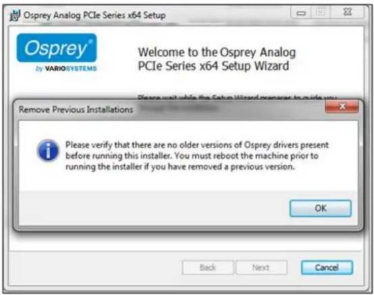
- Click OK. The Welcome to the Setup Wizard window displays (Figure 2).
Note: The version number may be dierent.
Figure 2. Welcome to the Setup Wizard

- Click Next. The End-User License Agreement window displays (Figure 3).
Figure 3. End-User License Agreement
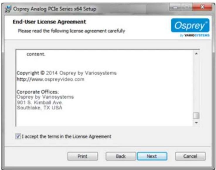
- Read the end-user license agreement. Click I accept the terms in the license agreement.
- Click Next. The Video Standard window displays (Figure 4).
6 Osprey
Figure 4. Video Standard window
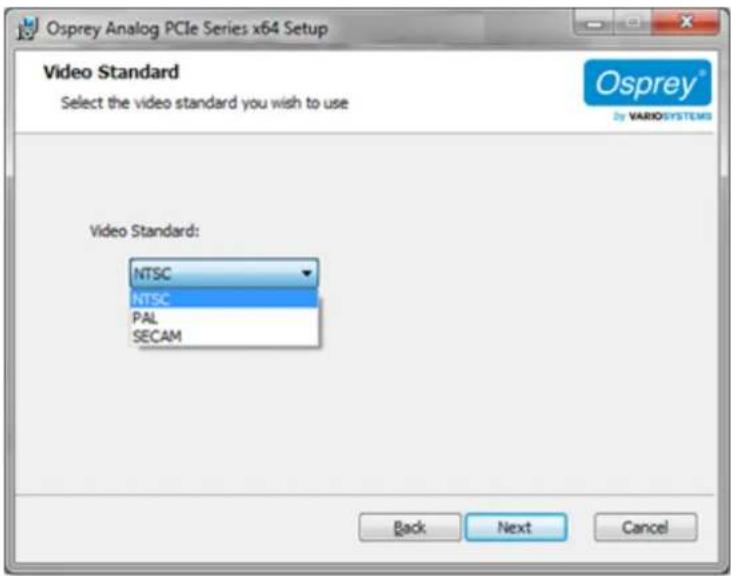
- Click a video standard from the drop-down list.
- Click Next. The Desnaon folder window displays (Figure 5).
Figure 5. Desnaon Folder window
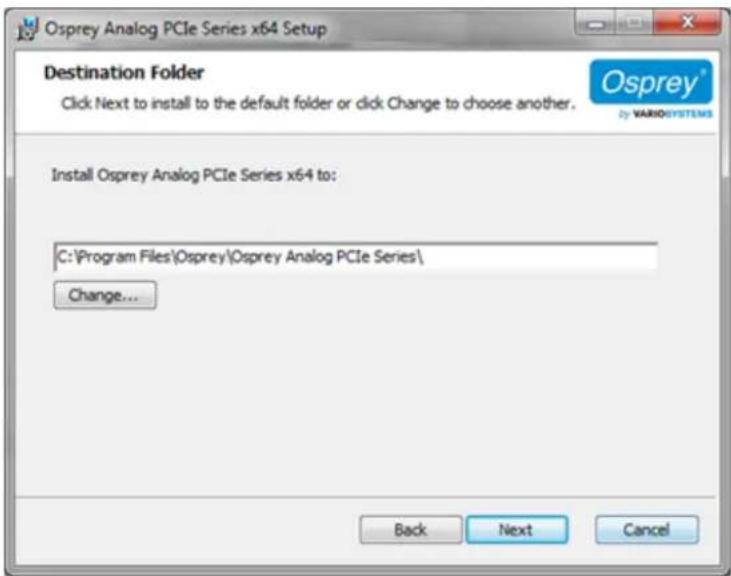
- Click Next. The Ready to Install window displays (Figure 6).
Note: Click Change to change the desnaon folder.
Figure 6. Ready to install
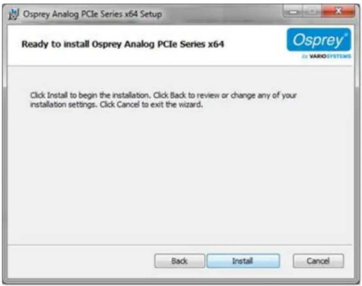
- Click Install. The Windows Security window displays (Figure 7).
Figure 7. Windows Security window
- Click Install. When the installaon nishes, the Install Completed window displays (Figure 8).
Figure 8. Install Completed
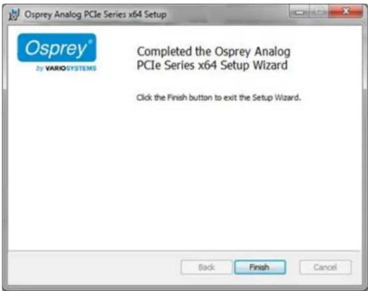
- Click Finish. The restart window displays (Figure 9).
Figure 9. Restart window
- Click Yes to restart your system now.
Installing the video capture card
Aer you install the Osprey Analog PCIe Series driver, physically install the video capture card into the computer.
All computer cards are sensitive to electrostac discharge. Slight electrostac discharges from clothing of from the normal work environment can adversely act these cards. By following these simple guidelines, however, you can minimize the chance of damaging the Osprey video capture card.
- Handle cards only by the non-conducng edges.
- Do not touch the card components or any other metal parts.
- Wear a grounding strap while handling the cards (especially when located in a high stack area).
• Properly ground your computer to avoid stac discharge. - Ensure the workstaon is powered o and the power cord is unplugged before installing any components.
- If you are not familiar with how to install a PCI Express bus card, refer to the system's document on for more complete, step-by-step instrucons.
- Install the card only in UL Listed computers that include instrucons for user-installed accessories.
To install the video capture card:
- Power down and unplug your computer.
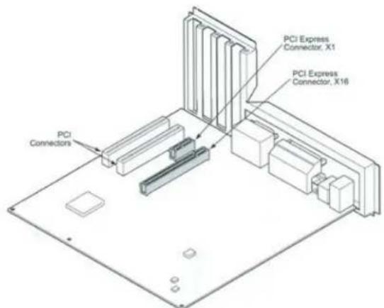
- Remove the computer's cover and locate an empty PCI Express slot.
WARNING! Be sure to install the card in the PCI Express slot. This slot is usually black. Refer to the following diagram as a guide. Placing the card in the wrong slot can damage the card.
Figure 10. Typical PCI Express Slot diagram
- Remove the cover screw from the empty PCI Express slot's cover, set the screw aside.
-
Remove the slot cover.
-
Remove the Osprey card from its an-stac bag.
- Insert the Osprey card into the desired PCI Express slot and make sure it is seated evenly.
- Secure the back panel of the card with the slot's cover screw.
- Replace the computer cover.
- Plug the power cord into an electrical outlet and turn the computer on.
Installing the hardware
Aer you install the Osprey Analog PCIe series card and restart the computer, the InstallShield Wizard displays and guides you through the installaon process.
To install the hardware:
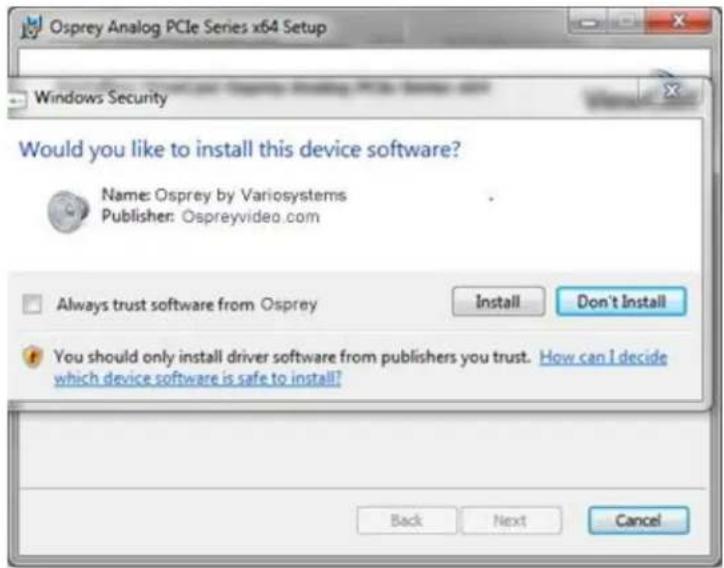
- The New Hardware Wizard runs and the Windows Security window (Figure 11) displays. Click Install.
Note: You can enable Always trust soware from "ospreyvideo.com." to eliminate this step in the future.
Figure 11. Windows Security window

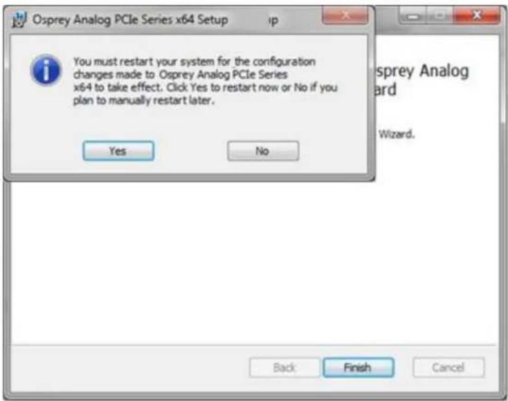
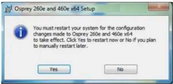
The device soware installs. When the installaon is complete, the Osprey setup window appears (Figure 12). You must restart your system for the conguraon to take eect. Click Yes.
Figure 12. System Sengs Change Window
Multiple board types
All Osprey video capture cards are designed to co-exist with other Osprey cards within praccal limits of slot placement, available power, and the upper limits of system and CPU performance. Each class of Osprey devices requires its own Windows driver.
class 1: o100, o200, o210, o220, o230
class 2: o300
class 3: o440
class 4: o530, o540, o560
class 5: o700e HD and o710e HD
class 6: o240e, o450e
class 7: o100e, o210e, o260e, o460e
class 8: o820e, o825e, o845e
This user guide applies only to class 7.
For example, if you install an Osprey 530 and an Osprey 460e card in the same computer, you must install separate drivers for each board.
Adding or moving boards
When you add or move boards aer you install the Osprey Analog PCI series driver, the following two scenarios exist.
A. You added a board of a dierent class to a computer that already contains another board. For example, an Osprey 240e is already installed with its current driver on the computer. You want to add an Osprey 260e/460e card. You must install the driver installaon package for the new board to work.
B. You moved a board from one slot to another, or added another board of the same type. For example, an Osprey 240e card is installed in the computer, and you want to install another Osprey 240e card. In this case, the following sequence takes place.
To add or move boards:
- The New Hardware Wizard runs and the Found New Hardware window displays followed by the Digital Signature Not Found window.
- Click Connue Anyway. (The Digital Signature Not Found window will only display on drivers that have not been WHQL cered. WHQL-cered drivers skip this step.)
- The Controller Installing window appears, and the text inside this window changes to Osprey Video Capture Device, Installing ... Then the Digital Signature Not Found window appears.
-
Click Connue Anyway. (Again, the Digital Signature Not Found window will only display on drivers that have not been WHQL-cered. WHQL-cered drivers skip this step. The Compleng the Found New Hardware window displays.
-
Click Finish. The Digital Signature Not Found window appears.
- The Digital Signature Not Found window appears once for each Osprey board you install.
- The Systems Seng Change window appears.
- Click Finish to restart the computer.
- The Osprey Analog PCIe Series card is now ready for use.
Setting Video Driver Properties
Aer installing the Osprey card and Analog PCIe series driver, you need to access the card's sengs and possibly modify them to t your needs. This manual takes you step-by-step through the card sengs. Start by opening the OspreyCong ulity.
You need to use a DirectShow applicaon such as Microso Windows Media® Encoder or RealProducer®. We also access card property pages through Osprey Cong, the ulity bundled with our 4.6 driver suite. Once installed you can see the card's default sengs and change them as needed.
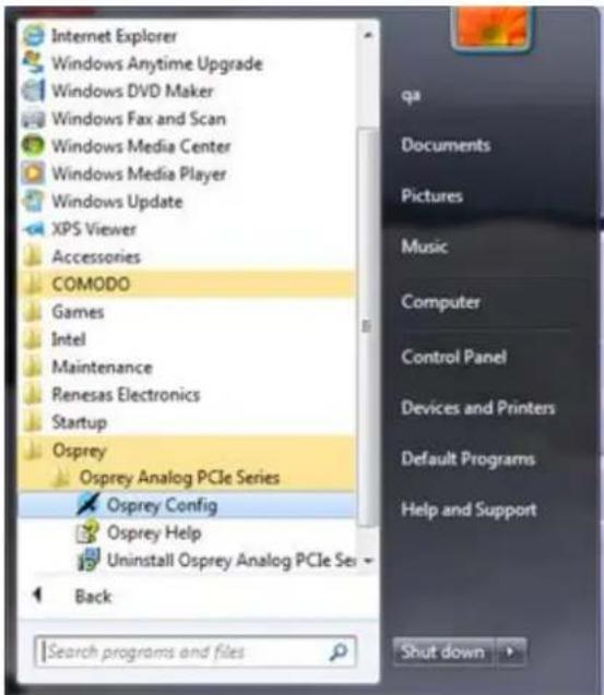
To open Osprey Cong click All Programs in the Start menu of your Windows computer ➤ Osprey ➤ Osprey Analog PCIe Series ➤ Osprey Cong (Figure 13).
Figure 13. Accessing the OspreyCong Utility
Note: Other DirectShow applicaons can nd the property page too. If you use a third-party applicaon, you will nd how to access the card's sengs in the third-party applicaon's documentaon.
OspreyConfig's initial processing sequence
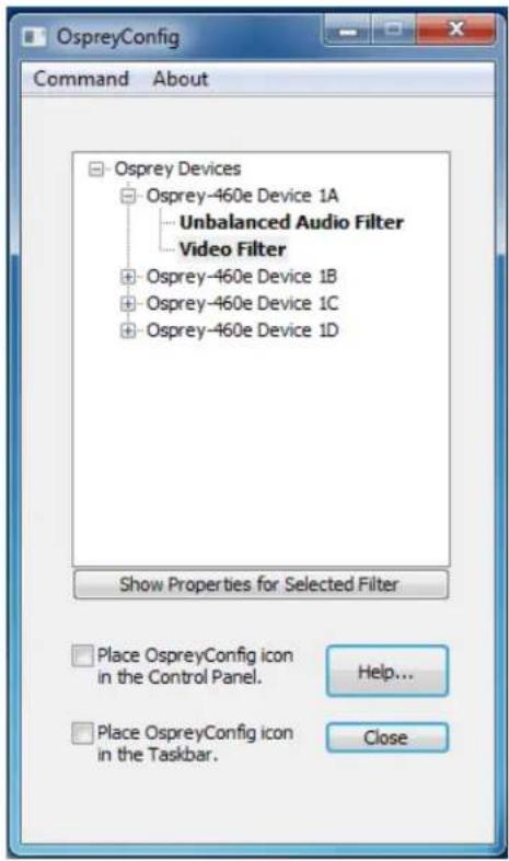
Aer clicking on the Osprey Cong icon, the rst screen of the applicaon appears (Figure 14) displaying the cards and devices installed on your computer. The main window (Figure 14) depicts a tree view of Osprey audio and video capture Iters installed in the system. They are organized by device – each device has an Audio Filter and Video Filter. If SimulStream is installed, there may be mulple Video Filters listed under each device.
Figure 14. Inial OspreyCong user interface
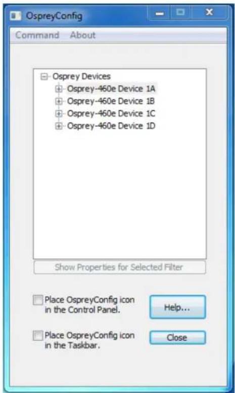
In this example, the computer in use has one card and four devices. The card can take a single input and stream the content dierently, for example, you can use several bit rates, sizes, and formats.
The OspreyCong window has the following controls:
| + | Click the + icon on the le side of the device you want to congure, to change the properes of that device.Note: You can also double-click on the name of a lter to display its properes. |
| Show Properes for Selected Filter | This buon becomes acve when you choose a device or video lter. The device properes window displays (see Understanding the device properes window). |
| Place OspreyCong icon in the Control | Select this check box to place the OspreyCong icon to appear in the Control Panel that next me the Control Panel is opened. |
| Panel | Note: You need to have administrave rights on the machine to add OspreyCong to the Control Panel or remove it. A diagnosc message displays if you try this command without administrave rights.Vista or later Note: If you are running Windows Vista or later, in addition to having administrave rights you need to open OspreyCong with the Run as Administrator opon. If you see a diagnosc message to this eect, exit OspreyCong: Command ➤ Exit OspreyCong rather than using the Close buon. Right click on the OspreyCong icon, select Run as Administrator and retry the command. |
| Place OspreyCong icon in the Taskbar | Select this check box to immediately display the OspreyCong icon in the nocaon area at the right end of the Taskbar. The icon reappears each me the current user restarts the user session. Mulple users control this seng individually as they log onto the system. |
| Help | Click Help to access the Help les. |
| Close | Click Close to close OspreyCong's main applicaon window. If you place OspreyCong in the taskbar, it is removed and the applicaon remains loaded to respond to clicks on that icon. |
Seng Video Driver Properes
Figure 15 shows the user interface that appears when you select a liter. In this example, the Osprey 460e Device 1A is expanded and Video Filter is highlighted.
Figure 15. Selecng a device for conguraon
Understanding the device properties window
Osprey's device properes window enables you to view and change the default sengs of the driver. Once you are familiar with the video card's properes, you can make changes to get the opmum performance from your card and change sengs in real me.
Device properes are visible through tabs to select dierent controls (Figure 16).
Figure 16. Osprey Video Device Properes window tabs

The Osprey Analog PCIe Series cards have the following tabs:
| Input tab | Select the video input, NTSC / PAL / SECAM video standard. |
| Video Proc Amp tab | Set brightness, contrast, saturaon, hue, gamma, and sharpness. |
| Video Decoder tab | Select the video standard – NTSC, PAL, SECAM. |
| Debug tab | Sets Osprey Analog PCIe series internal test controls. The user should only use these controls when instructed by Osprey support. Doing so without proper instrucons may result in system instability or in the system crashing. |
| RefSize tab | Set the reference size for cropping. |
| Filters tab | Enable SimulStream®, deinterlace/ detelecine. |
| Device tab | Use various other specialized controls. |
| Capons tab | Set up on-video closed capon rendering. |
| Logo tab | Set up on-video logos. |
| Size and Crop tab | Set the default size, enable cropping, and set the cropping rectangle. |
On some systems you may see additional tabs besides the ones listed. The additional tabs are system-supplied, for-your-informaoon only, and contain no controls that you can set.
Common buons
The following informaon applies to controls that are not interact.
| OK | Commits the changes you have made on the currently displayed page, and exits the dialog. |
| Cancel | Exits the window without comming the changes you have made on the currently displayed page. Changes made before the most recent click ofApplyare not cancelled. |
| Apply | Commits the changes you have made on the currently displayed page, without exing the dialog. |
Some controls are interactive – changes you make are immediately updated on the video. Examples are the brightness, contrast, hue, saturaon, and sharpness controls, the graphical gamma control; and the graphical sizing and posioning controls for logos. OK, Cancel, and Apply have no effect on these controls.
In all cases, Help accesses this help module. The buon on each tab displays the descripon for that page.
Note: OK and Apply commit only the changes on the currently displayed page. To set changes on three different pages you need to click Apply twice and OK once.
Per-device, per-pin, and global controls
Some controls operate on the device as a whole, while other controls operate on individual Iters and pins. Controls on the following tabs are per-device. A change to any of the following controls aects all pins and Iters on the device:
- Video Proc Amp
- Video Decoder
- Input
- Filters
- RefSize
- Device
Controls on the following tabs are per-Iter and per-pin. Changes on these tabs aect only the Iter or pin specied:
- Crop
- Logo
- Capons
At the top of these three tabs is a control group named Pin Select. The three buons in this group determine whether changes you make will select both the capture and preview pin associated with the iter, or just the pin – preview or capture – that you have selected.
Figure 17. Pin Select buons
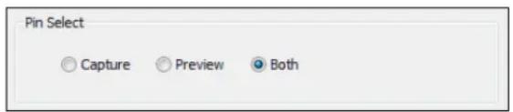
When you enable Both, changes you make to the setup apply to both the capture and preview pins.
You can have dierent setups for the two pins. For example, you could enable a feature on the capture pin but not on the preview pin. When you enable Capture, the current logo sengs for the capture pin are loaded, and changes you make apply only to the capture pin, not to the preview pin. Preview works the same way. The DirectShow Pin Properes that applicaons may display for Capture and Preview pins are always separate for each pin.
Some of the controls on the Filters tab and the Device tab are global to all Osprey Analog PCIe Series devices. Global controls are noted as such in their descripons. The raonale is either that the control is or logically global to all devices; or that it is rarely used, less important control, such that users will prefer the convenience of seng the control just once for all devices. Global controls aect only Osprey Analog PCIe Series devices, not other kinds of Osprey cards that might be in the system.
Input tab
All controls in the Input tab apply to all Iters and pins on the currently selected device. If you have mulple Osprey cards, set the input individually for each card.
Figure 18. Input tab
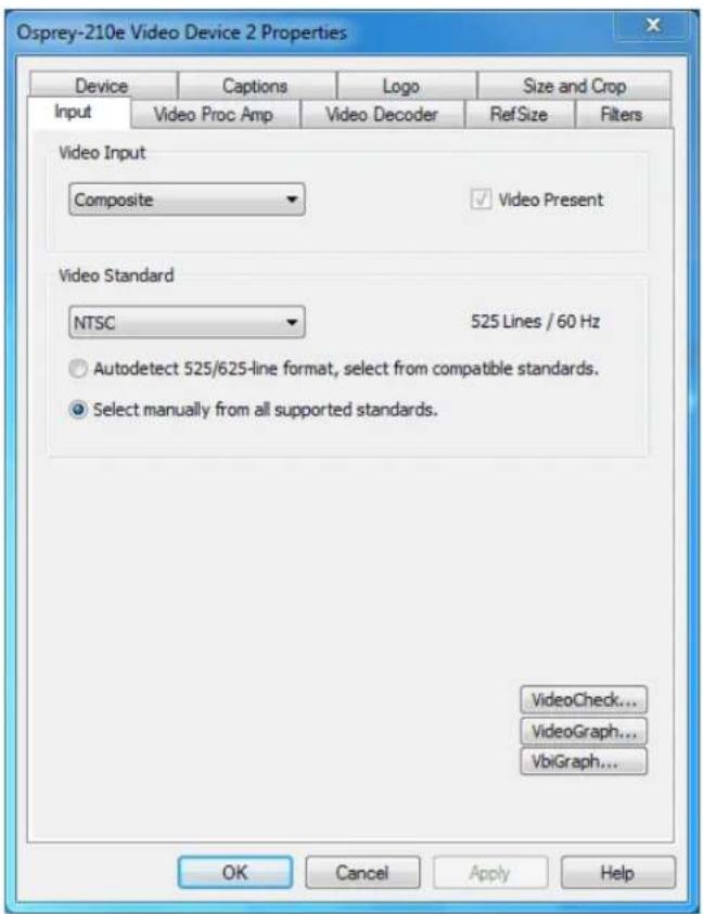
The Input tab has the following controls.
| Video Input | Allows you to select the video signal source. |
| Video Present | This indicator is enabled when video is present. |
| Video Standard | Select the standard dierent countries or geographical areas (Figure 18) from the drop-down list. The North American standard is NTSC. The Japanese standard is NTSC-Japan. The ve PAL standards, B, D, G, H, and I are similar and treated the same way by the Osprey driver. The driver also supports PAL-M and N and SECAM video. |
| Ulies | Allows you to launch ulies that are useful for seng up and checking video:VideoCheckVideoGraph |
Osprey Analog PCIe Series User Guide
| • VbiGraph |
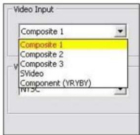
Video Input group
The main Video Input control is a drop-down list for selecng the video signal source.
Figure 19. Osprey 460e Video Input group
Osprey 260e
The Osprey 260e is a single channel card. It has mulple video inputs, but you can only select one of them at a me.
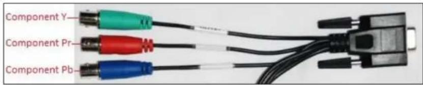
Which inputs are actually selectable depends on the type of dongle you use. The Osprey 260e ships with a YPrPb (Component) dongle (Figure 20) and an adapter (Figure 22).
You can use YPrPb dongle three ways. First, you can use it for YPrPb (Component) inputs as shown in Figure 20.
Figure 20. YPrPb (Component)
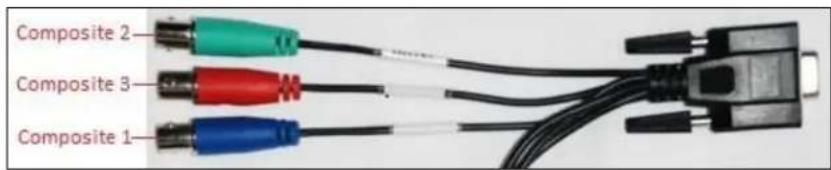
This dongle also provides three Composite inputs. Only one of these can be selected at a me. The numberings in the selecon control correspond to the lines on the dongle as shown in Figure 21.
Figure 21. Selecon control numbering
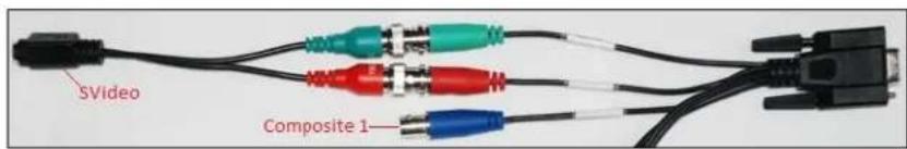
Finally, with an additional adapter, a SVideo source can be connected to this dongle. The SVideo conncon replaces Composites 2 and 3, but Composite 1 is sll available as shown in Figure 22.
Figure 22. Adapter
You can also use a Composite/SVideo dongle with the Osprey 210e, the connecons are shown in Figure 23.
Figure 23. Composite/SVideo dongle
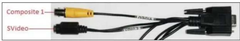
The Composite line is Composite 1 in the selecon control. With this dongle, you cannot use the Composite 2, Composite 3, and YPrPb connecons.
Osprey 460e
The Osprey 460e has four separate independent video channels that can run simultaneously. Unless you each an oponal auxiliary expansion connector, the only input available is the Composite BNC on the board's moung bracket. The four connectors correspond from top to boom to channels A, B, C, and D. In this case the Video Input control shows just the one input for channel, which will be selected automacally.
The Osprey 460e's oponal auxiliary expansion connector adds ve additional inputs, more than three mul-purpose physical connectors, for each of the four channels:
- Component (YPrPb) uses all three of the auxiliary video connectors
• S-Video (Y-C) connects an S-Video connector to two of the connectors via an adapter cable
• Three additional composite inputs
The labeling on the expansion panel shows which connectors to use for each purpose. The inputs for each channel, along with the channel's bracket connector, can only be used one at a me. The hardware automacally senses at system start whether the expansion connector is plugged in, and if it is then all six inputs appear in the Video Input control.
Changes to the video input take eect as soon as you click Apply or OK.
Video standard group
Figure 24. Video Standard eld
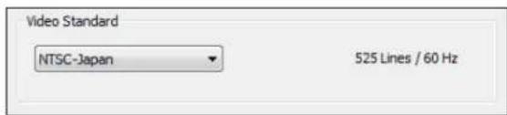
The Video Standard control group is a copy of the controls on the Video Decoder tab.
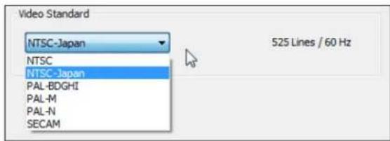
The North American standard is NTSC. The Japanese standard is NTSC-Japan. The ve PAL standards, B, D, G, H, and I are similar, and are treated the same by the Osprey driver. The driver also supports PAL-M, PAL-N, and SECAM video. PAL-N is the Argenne standard with a 3.58 MHz subcarrier. PAL-M is a standard that uses the PAL method of color encoding combined with an NTSC-type 525-line, 29.97 Hz frame format.
Changes to the video standard take eect as soon as you click Apply or OK. If video is currently streaming you will not see correct video unless the signal format on the input is the same as the video standard you have just selected. If you are changing from a 625-line standard to a 525-line standard and your video is larger than the maximum size for the 525-line format, video will not restart until you adjust the video size to an allowed value.
Figure 25. Video Standard drop-down list
Ulies
The buons in the lower right corner of the Input property page launch ulies that are useful for seng up and checking video.
These ulies run independently of the property pages. They connue to run aer property pages are closed. Each ulity also has a device select control, so it can be switched to monitor another board.
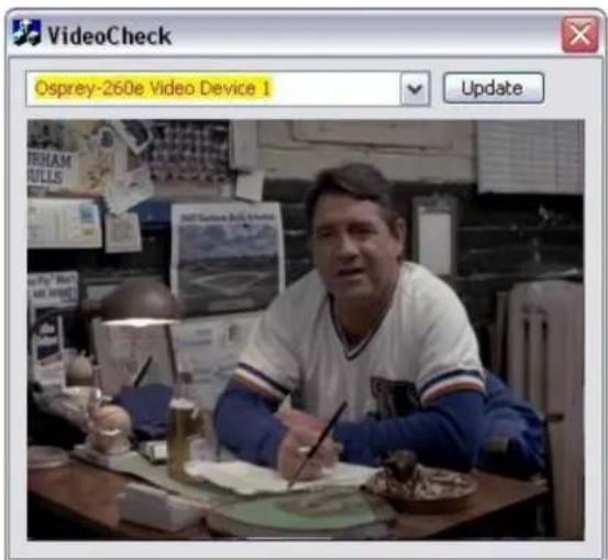
VideoCheck ulity
VideoCheck opens a simple video monitoring window (Figure 26). You can see the immediate effect of changes to your sengs. Most changes show up automatically as soon as you click Apply. You will need to click the applet's Update buon to see a change that alters the output size of the video.
VideoCheck uses one preview stream of video. If you do not have SimulStream installed, you can only view one preview stream at a me from each device (this is in addition to the main capture stream). If VideoCheck does not work, the rst thing to check is whether a preview stream is already running on the device.
Figure 26. VideoCheck ulity
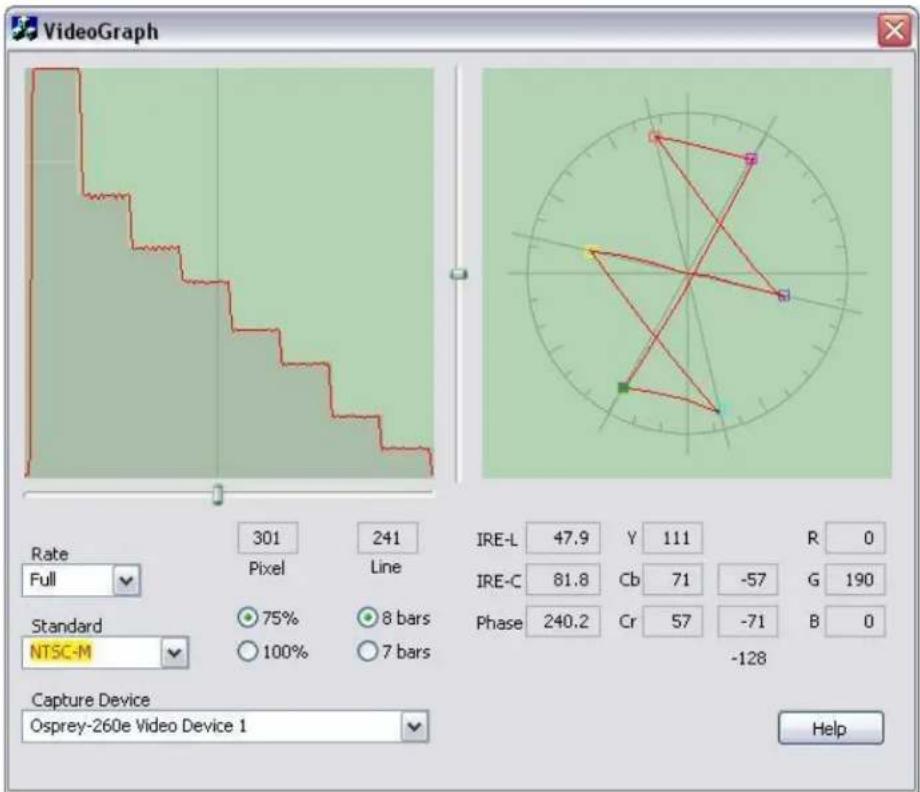
VideoGraph ility
The VideoGraph ulity (Figure 27) launches a vectorscope/lumascope ulity. VideoGraph is intended to be used with a color bar signal from a calibrated signal generator. It shows whether the signal and the card's Video Proc Amp sengs are calibrated to the correct luma and chroma levels.
In the picture, the le-hand panel shows the luma levels of standard 75 % NTSC color bars. The grey background shows the expected levels, and the red line shows the actual levels measured. The right-hand panel shows the chroma posions of the six colors. The small colored squares show the expected posions, and the points on the red signal paern should line up with them.
If there are discrepancies, you can use the driver's Brightness, Contrast, Saturaon, and Hue controls on the Video Proc Amp property page to adjust the levels.
If you don't have a signal generator available, you can get a general idea of how VideoGraph works by disconnecting the input signal and running it with the 75% or 100% no-signal color bar test paern. The driver's test paern will line up exactly with the VideoGraph's targets – IF the gamma seng is at the default posion. Soware-based Video Proc Amp controls alter the test paern levels; hardware based-controls do not. The gamma control, and in some cases the hue control, are soware based.
The vercal slider adjusts which video line displays. You may have to move the slider so that a line that has color bar informaon is selected.
The horizontal slider moves the horizontal cursor – the vercal line on the luma display. The data displayed at the lower right – IRE-L, etc. – is for the pixel selected by the horizontal cursor. Also, on the chroma display, the small solid rectangular cursor corresponds to the luma cursor, that is, if the luma cursor is on the red color bar, the chroma cursor will be at or near the red point in the chroma display.
There are controls to set the background markings for 75 % or 100 % signal levels, and for eight or seven bars – so that the markings correspond to the type of color bars your signal generator is making.
The Help buon on the applet brings up a message box with an alternate and slightly more technical descripon.
Figure 27. VideoGraph utility
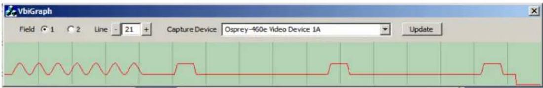
VbiGraph ulity
The VbiGraph utility (Figure 28) opens an applet that displays the raw waveforms of the video's Vercal Blanking Interval (VBI). The informaon on these lines may include closed capons (CC), wide screen signaling (WSS), vercal interval mecode (VITC), and teletext. The applet is useful as a diagnosc if the expected data is not being decoded – you can see if the required signal is there at all, whether it is in spec, and which line it is on.
The controls select the eld and line to be displayed. The only me you need the Update buon is when you switch between 525-line and 625-line video standards.
Figure 28. VbiGraph ulity
Osprey Analog PCIe Series User Guide
Video Proc Amp tab
Use the slider controls to set Brightness, Contrast, Hue, Saturaon, Sharpness, and Gamma (Figure 29). If preview video is running when you access this tab, you can see your adjustments interactively. These controls are implemented in hardware, and work as typically expected.
Figure 29. VideoProc Amp tab
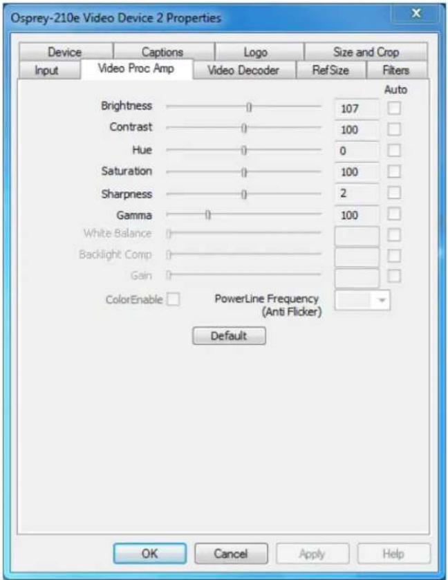
The Video Proc Amp tab has the following controls.
| Brightness and Contrast | These are terms for what one would call a contrast rao. It's a measure of a display system, dened as the rao of the brightest color (white) to that of the darkest color (black) that the system is capable of producing. A high contrast rao is a desired aspect of any display, but with the various methods of measurement for a system or its part, dierent measured values can sometimes produce similar results. The control exists in the event you need to change the rao of an incoming signal. |
| Hue | Hue adjustment is calibrated in degrees. It is implemented in hardware for NTSC video. An alternate soware implementation is used when PAL or SECAM standards are used. |
| Saturaon | In color theory, saturon or purity refers to the intensity of a speci hue. A highly saturated hue has a vivid, intense color, while a less saturated hue appears more muted and grey. With no saturon at all, the hue becomes a shade of grey. You can adjust the saturon level in the event a video feed alters it. |
| Sharpness | This slider has a small number of discrete posions corresponding to speci hardware lter sengs. Generally, the posions to the le result in smoother video, the posions to the right result in sharper video. If the seng is too sharp, fringes or ghosts appear at vercal boundaries. Because each step engages a dierent combinaon of discrete lters, the control may be non-linear in its acon. Some steps may result in slight dierences while other steps may result in large dierences. The eects of dierent sharpness sengs are easier to see when the video is completely sll, or is paused. |
| Gamma | The Gamma adjustment is calibrated at 0.01 mes the indicated value – that is, 30 refers to gamma correcon of 0.3, 100 to 1.0, and 300 to 3.0. Therefore, the video appears generally brighter when you move the slider to the le. |
| White Balance | This eld is an unused DirectShow feature and is not selectable. |
| Backlight Comp | This eld is an unused DirectShow feature and is not selectable. |
| Gain | This eld is an unused DirectShow feature and is not selectable. |
| Color Enable | This eld is an unused DirectShow feature and is not selectable. |
| PowerLine Frequency (An Flicker) | This eld is an unused DirectShow feature and is not selectable. |
| Default | Click Default to return to the default sengs. |
| Auto | This eld is an unused DirectShow feature and is not selectable. |
For all of the Video Proc Amp controls the driver maintains one set of seng per Osprey device. It does not maintain individual sengs for each input or type of input.
Changes made on this page apply to all video previews and capture pins on the currently selected device.
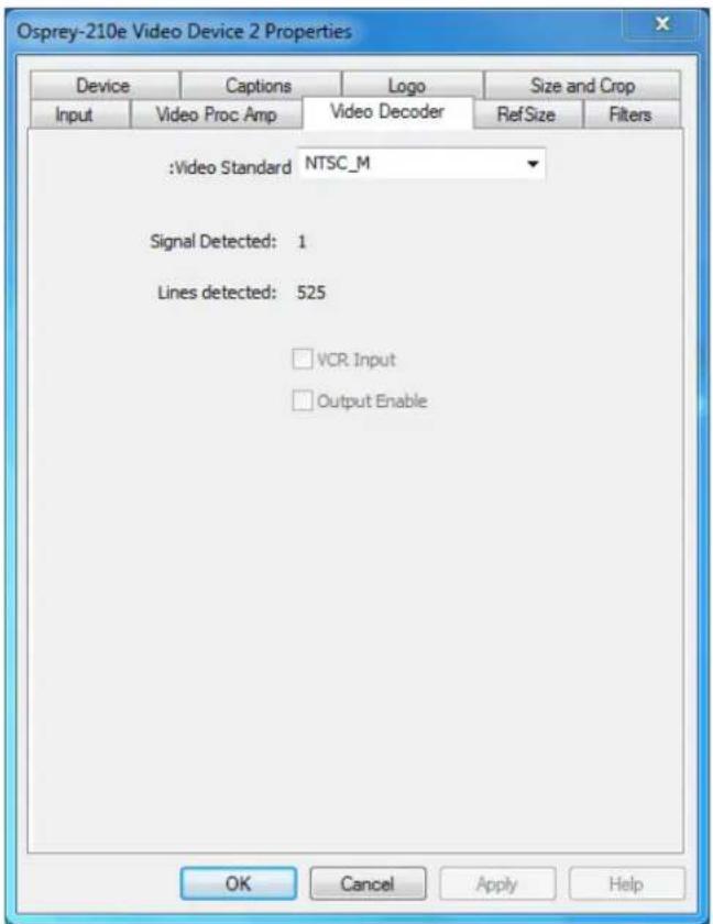
Video Decoder tab
The Video Decoder tab (Figure 30) is a Microso® DirectShow standard control for seng the NTSC/PAL/SECAM video standard.
Note: These controls are also on the Input tab. Most users nd the Input tab more convenient to use.
Figure 30. Video Decoder tab
Changes apply to all video previews and capture pins on the currently selected device. If you have mulple Osprey cards, you can set the input individually for each of them.
Changes made with this control take eect immediately. Apply really has no funcon on this tab. If video is running and you select a standard that does not match the incoming signal, the video is likely to freeze or glitch unl the signal matches again.
Osprey cards support the Signal Detect (0 or 1) and Lines Detected (525 or 625) status readouts. They do not support the VCR Input or Output Enabled controls, which are always disabled.
The Video Decoder tab has the following controls.
| Video Standard | Select the video standard. |
| Signal Detected | When the card does not detect the input signal, this eld displays a 0. When the card detects the input signal, it displays 1. |
| Lines detected | This eld displays the number of lines the card detects in the input signal. |
| VCR Input | This eld is a DirectShow feature that is not implemented. |
| Output Enable | This eld is a DirectShow feature that is not implemented. |
RefSize tab
The RefSize tab (Figure 31) controls features related to the reference size, format, and proporons of the video. These controls are not commonly used. Most users can set up this page once and never refer to it again.
Note: This tab does not provide everyday control of the nal output size of your video. Control nal output size either from your applicaon, from the Crop tab, or from the Pin Properes dialog described in the next secon.
Changes made on this page apply to all video previews and capture pins on the currently selected device.
Figure 31. RefSize tab
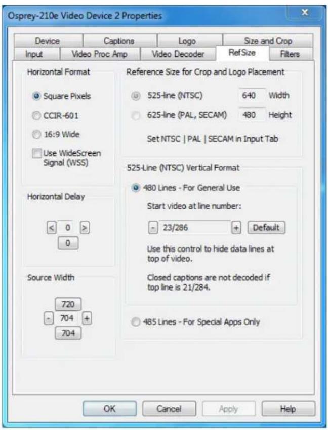
The RefSize tab has the following controls.
| Horizontal Format | Sets the horizontal mode for the output. Opons include Square Pixels, CCIR-601 seng, 16:9 Wide, and Use WideScreen Signal control. |
| Horizontal Delay | The horizontal delay control moves the video horizontally in the capture or preview frame. |
| Source Width | Use the Source Width control to trim the black le and right edges of an image. |
| Reference Size for Crop and Logo Placement | This part of the dialog box displays the results of more fundamental sengs made elsewhere in the dialog box. |
| 525-Line (NTSC) Vercal Format | This control is for NTSC users. It has no eect for PAL and SECAM 625-line video standards. |
Horizontal Format
Figure 32. Horizontal Format
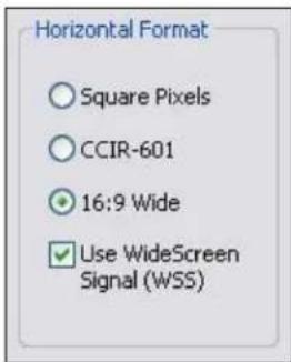
The Horizontal Format has the following controls.
| Square Pixels | Use the Square Pixels seng for normal 4:3 video (Figure 32) that is viewed via a computer monitor. This seng results in a square aspect rao sampling of the source video. It also results in a source image of 640 x 480 for 525-line standards and 768 x 576 for 625-line standards. |
| CCIR-601 | Use the CCIR-601 seng for 4:3 video that is viewed on a dedicated video monitor. This seng results in a CCIR-601 aspect rao sampling of the source video. It results in a video input horizontal size of 720 pixels for both 525-line and 625-line standards. This sizing is standard for dedicated monitors but the resuling video appears horizontally stretched (525-line) or squeezed (625-line) on a computer monitor.It is more ecient to set the horizontal mode to match the size of the output. For example, if your target video size is 640 x 480 using Square Pixel sizing in PostProcessing Mode, it will avoid an unnecessary soware scaling step in the driver. |
| 16:9 Wide | Select 16:9 Wide for 1.85:1 anamorphic video such as DVD content and any PAL widescreen content. The output video size is 852 x 480 for 525-line standards, and 1024 x 576 for 625-line standards. To see output of this size, you have to also select this size in your applicaon. |
| Use WideScreen Signal (WSS) | The Use WideScreen Signal (WSS) control enables automac sidebars and leerboxing when the input video aspect rao does not match the output aspect rao. If the aspect rao of your content is subject to change between 16:9 and 4:3, it is useful to enable this control.WSS is a line of the vercal blanking interval (VBI) that encodes the aspect rao of the video. It is normally line 20 of 525-line video and line 22 of 625-line video. It is generated by newer DVD players, and is present in PAL broadcast content.This control is useful for both 4:3 and 16:9 input formats, and for both 4:3 and 16:9 output formats. When selected, it has the following eects:4:3 video on a 4:3 window shows without sidebars or leerboxing4:3 video on a 16:9 window shows with sidebars16:9 video on a 16:9 window shows without sidebars or leerboxing16:9 video on a 4:3 window shows with leerboxing |
Changes to this control take eect as soon as you click Apply or OK. If video is currently streaming, you may not see correct video until you have adjusted the video output size. If your output size is larger than the new reference size, you have to adjust the output size to be not larger than the reference size before the stream can be restarted.
Horizontal Delay
Figure 33. Horizontal Delay
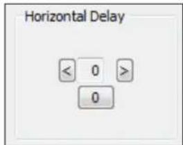
The Horizontal Delay control works in conjuncon with the Source Width control to adjust the width and borders of the acve video eld (Figure 33).
The Horizontal Delay control moves the le edge of the video horizontally in the capture or preview frame. Video devices dier in their ming characteriscs, so some devices may need dierent adjustments from other devices. Use the le and right arrow buons to move the acve video to the le or right. Click 0 to restore the default zero seng. The range of adjustment is from -15 to +15.
This control is interactive. Use this control while a preview stream is being displayed to see the changes immediately.
If you see a black line to the le of the acve video, use the le arrow buon to move the acve video to the le. The video can be too far to the le, so that several columns of pixels are not visible. In this case, use the le arrow buon to move the video leward unl the black line disappears.
This control aects all streams on the selected video channel.
Source Width
Figure 34. Source Width
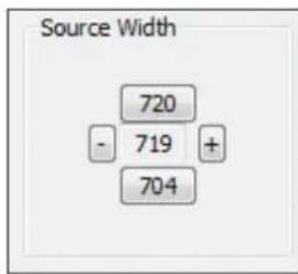
The Source Width control (Figure 34) works in conjuncon with the Horizontal Delay control to adjust the width and borders of the acve eld.
The Source Width control adjusts the width of the poron of the video line that is captured. It moves the right edge of the video horizontally in the capture or preview frame. (This control does not move the le edge – the le edge is aected only by the Horizontal Delay control.) The minus buon moves the right edge to the le the plus buon moves it to the right. Adjustments are relave to the standard CCIR horizontal size of 720 pixels. The [720] buon resets the width to that default. The [704] buon sets the width to a useful smaller size. The range of adjustment is from 688 to 720.
To trim an image:
Perform this adjustment in conjuncon with the Horizontal Delay adjustment, as follows:
- Make the adjustment with a live preview stream running, so you can see changes immediately.
- Use the Horizontal Delay control to set the le edge of the video.
- Use the Source Width adjustment to set the right edge of the video.
You can get the same results using the cropping control (Size and Crop tab) but there are dierences.
- The Source Width control aects all pins and all Iters on the device, whereas the crop control must be set separately for all SimulStream Iters.
- Source Width control uses less CPU resources than cropping in the specific case of 525-line (NTSC, PAL-M) video that is uncropped and in square pixel (640 x 480) format.
The driver performs the source width adjustment in hardware if possible; otherwise it performs it in sware. The following table summarizes the behavior of the control. The column “Adds CPU” refers to whether seng the control to a value other than 720 increases CPU usage beyond what is required by other aspects of the format.
| Video Type | Format | HW or SW | Adds CPU | Granularity |
| 525-line | Square Pixels | HW | No | 1 |
| CCIR | SW | Yes | 4 | |
| Widescreen | SW | No | 4 | |
| 625-line | Square Pixels | SW | No | 4 |
| CCIR | SW | Yes | 4 | |
| Widescreen | SW | No | 4 |
Reference Size for Crop and Logo Placement
Figure 35. Reference Size for Crop and Logo Placement
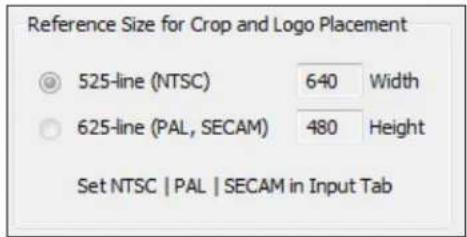
This part of the dialog is read-only because you do not set it directly – rather, it shows the results of sengs made elsewhere in the dialog.
The sengs shown by the 525-line / 625-line buons react the video standard selected in the Input or Video Decoder tab (Figure 35). NTSC and PAL-M formats result in 525-line, 29.97 frame per second video. PAL (other than -M) and SECAM formats result in 625-line, 25 frames per second video.
The Height and Width elds show the size of the incoming video based on all the sengs you have made. They react the video standard (NTSC, PAL, or SECAM) that you have selected on the Input Property Page, and the seng in the adjacent Horizontal Format group. They are updated when you click Apply for these changes.
525-Line (NTSC) Vercal Format
Figure 36. 525-Line (NTSC) Vercal Format

This control is only meaningful for NTSC users. It has no eect for PAL and SECAM 625-line video standards.
Select 480-line video for all normal applicaons and specialized applicaons. Select 485-line video for specialized applicaons.
When you select 480-line video, you can select which video lines should be the top line of displayed or captured video. For non-broadcast applicaons, all video lines starng with 21 / 284 can be part of the
Osprey Analog PCIe Series User Guide
displayed video. In lms and analog broadcast video, however, lines 21 and 284 are oen used for Closed Capon. In broadcast video, lines 22 and 285 are somemes used for proprietary ancillary data. If these lines are used for data they will appear as moving bands or streaks across the top lines. Therefore, the most generally useful start lines are 23 / 286.
Some broadcast video also uses additional top line pairs for ancillary data. We are seeing cases where the top line has to be set to lines 26 / 289 to hide all the data lines.
You can set start lines all the way up to 27 / 290. (On the PCI products which have a Direct Mode opon, PostProcessing Mode must be set in order to have top lines below 23 / 286.)
When the start lines are below 23 / 286, the boom of the video frame spills o the boom of the 485-line NTSC-standard frame. In this case the driver adds black lines at the boom of the frame.
Note: If you select start line 21 / 284, Closed Capons cannot be decoded.
Changes to this control take eect as soon as you click Apply or OK.
Filters tab
The Filters tab (Figure 37) covers two independent technologies: SimulStream and deinterlacing. Funconality for both technologies exists on this tab.
Figure 37. Filters tab
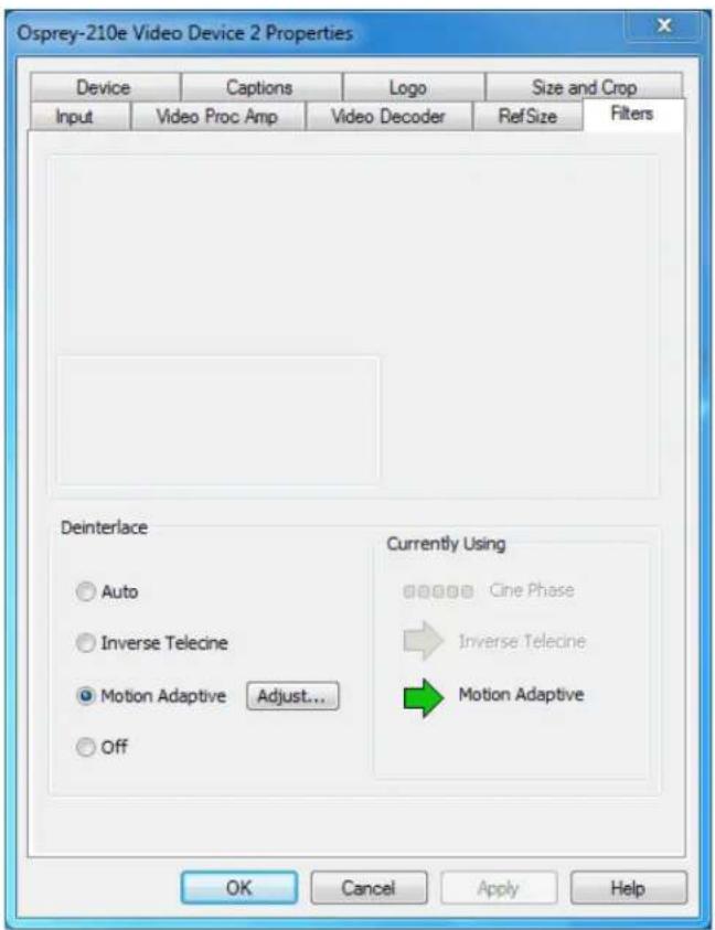
The RefSize tab has the following controls.
| SimulStream | Enable SimulStream or SimulStream evaluaon mode, and to specify how many Iters will be exposed. (This control group is not applicable to the Osprey 100e.) |
| Deinterlace | Deinterlace sengs are applied and stored per-device and are applied to all Iters and pins associated with a device. |
| Currently Using | The read-only indicators allow you to see the current algorithm. |
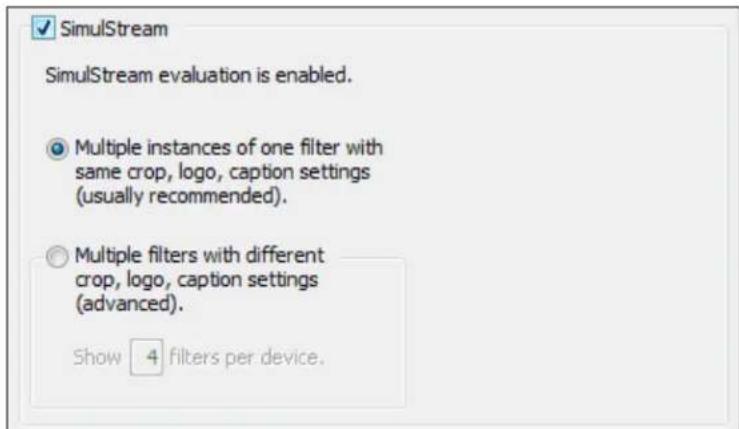
SimulStream
Use this control group (Figure 38) to enable SimulStream or SimulStream evaluaon mode, and to specify how many Iters will be exposed.
Note: The Osprey 100e and 210e do not support SimulStream.
SimulStream is a purchased soware opon. It makes a single hardware device appear as several separate devices capturing the same input stream. Each stream can have dierent size, color format, frame rate, crop, logo, and caponing. You can have mulple video capture streams in a single applicaon, or mulple applicaons each with one or more capture streams.
The driver includes an evaluaon version for free. Evaluaon mode works the same as licensed SimulStream except that an evaluaon mode graphic is always displayed on the video. For details about purchasing and installing SimulStream, refer to ospreyvideo.com.
Figure 38. SimulStream
Changes to SimulStream sengs take eect only aer the system is restarted.
For more background about Devices, Filters, Pins, and their relaon to SimulStream, refer to Filters, Pins, and Properes.
Figure 39. SimulStream enabled
The check box at the top of the group (Figure 38) turns on SimulStream for the currently selected device. The line of text below the check box conrms whether a SimulStream license is installed on the system, whether SimulStream is enabled or disabled, and if enabled, whether it is enabled in licensed or evaluaon mode.
SimulStream is enabled individually for each device. When you click OK or Apply, the driver advises you to restart your applicaon if this is needed. You can use SimulStream in two ways:
- One Iter
- Mulple Iters
One Iter
Figure 40. One Iter
Multiple instances of one filter with same crop, logo, caption settings (usually recommended).
You can have as many streams from the device as you want. They can each have a dierent size, color format, and frame rate. The term one Iter means all streams have the same Osprey custom properes. Specifically, cropping, logos (watermarks), and NTSC Closed Capon rendering sengs must all be the same for all streams on the device.
The advantage of this mode is that it is simpler. If you are not using Osprey custom cropping, logos, or closed capons, or if all streams have the same sengs, this mode is recommended.
This seng aects all Osprey Analog PCIe series cards served by the currently accessed driver. When you click OK or Apply, the driver will advise you to restart the system or your applicaon if needed.
Mulple Iters
Use this mode (Figure 41) if you are using Osprey custom cropping, logos (watermarks), and NTSC Closed Capon rendering, and want each stream to have separate sengs for these items.
Figure 41. Mulple Iters
○ Multiple filters with different crop, logo, caption settings (advanced).
Show 4 filters per device.
This mode is denitely more complicated than the one liter opon just described – so only use it if you are sure you need it.
Note: You do not have to use the Mulple Filters mode if the only things you want to be dierent on dierent streams are the video output size, color format, and/or frame rate. The applicaon stores these sengs, not the driver.
The term "mulple Iters" refers to the method of saving and accessing these dierent sengs. You can have 2 to 9 dierent Iters, each holding dierent sengs. The number of sengs is determined by the edit box in Figure 38 the Show [4] Iters per device eld.
For example (for the Osprey 260e) if you elect to have 4 Iters per device, each with separate crop, logo, and capon sengs and the underlying device has had the name Osprey 260e Video Device 1, when you open a list of capture devices with SimulStream enabled, you see Osprey 260e Video Device 1.1, Osprey 260e Video Device 1.2, and ...1.3, and ...1.4.
For example (for the Osprey 460e), the designaons would add an A, B, C, or D to indicate the channel number on the board. Therefore, for Osprey 460e Video Device 1A, when SimulStream is enabled, you will see Osprey 460e Video Device 1A.1, osprey 460e Video Device 1A.2, and ...1A.3, and ...1A.4.
To set the custom properes for one of these Iters, select it from the device list and open the driver properes dialog. The tle at the top of the window conrms you are seng up, for example, Osprey 460e Video Device 1A.2. When you set crop, logo, and capon sengs, they are saved separately for Device 1A.2 and do not aect Devices 1A.1, 1A.3, or 1A.4. Sengs that are not per-Iter – such as Reference Size or the Video Proc Amp sengs –aect all Iters on the underlying Osprey 460e Video Device 1A.
Later, whenever you select one of the four Iters as your capture Iter, the Osprey custom crop, logo, and capon sengs previously set for that Iter is enabled automacally.
You can have mulple streams on each Iter. For example, you could have four streams consisting of two instances of Osprey 260e Video Device 1.1, and two instances of Osprey 260e Video Device 1.2. The first two instances will have Iter 1.1's sengs; the second two instances Iter 1.2's sengs.
This seng aects all Osprey 260e and 460e devices in the system. When you click OK or Apply, the driver prompts you to restart your applicaon if this is needed.
Deinterlace
Figure 42. Deinterlace sengs
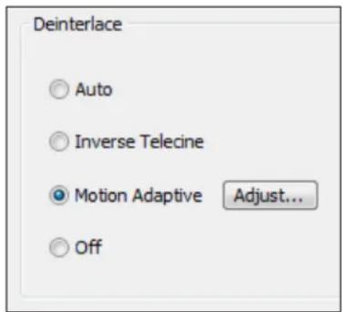
The deinterlace group has four radio buons.
| Auto | Apply inverse telecine deinterlacing to all telecine video. Apply moon adapve deinterlacing to all video that is not telecine. Switch dynamically between the two modes as the content changes. Available for 525-line (NTSC) video only. |
| Inverse Telecine | Apply inverse telecine deinterlacing to all telecine video. Perform no deinterlacing of video that is not telecine. Available for 525-line (NTSC) video only. |
| Moon Adapve | Apply moon adapve deinterlacing to all video. |
| Adjust... | Click this buon to display the Adapve Deinterlace window. See Adapve Deinterlace window for informaon on using this dialog box. |
| O | Perform no deinterlacing of any kind.Note: Before using this mode, refer to When to deinterlace. |
Deinterlace sengs are applied and stored per device and are applied to all Iters and pins associated with a device.
Changes to this control take eect as soon as you click Apply or OK.
When to deinterlace
When in doubt, deinterlace. In some cases, bad arfacts will be seen if you do not deinterlace.
| NTSC (29.97 fps) | When in doubt, use moon adapve deinterlacing rather than Inverse telecine. Moon adapve deinterlacing is not ideal for all content, but it works at least adequately with all content. Inverse telecine is ideal for telecine content – it completely removes interlacing arfacts – but for non-telecine content, inverse telecine is the same as no deinterlacing at all.When the content is known to be 100 percent progressive, it is advantageous to turn o deinterlacing. Video sharpness will be superior.Refer to background informaon below. |
| PAL/SECAM (25 fps) | When content is 100 percent progressive (shot by lm, universal, or progressive camera) it is advantageous to turn o deinterlacing. Video sharpness will be superior. |
| Vercal scaling | When the driver scales video it uses both elds of the frame as a single progressive frame unit. The frame has to be deinterlaced or progressive. If it is not, and there is moon in the video, the result in scaled video will be large jagged patches on vercal or diagonal edges. If you see these, it is a sign that you denitely need to turn on deinterlacing. (Refer to the notes at the end of this secon.) |
| Auto mode | In Auto mode, when the driver detects telecine sequences, it applies the inverse telecine algorithm; otherwise it falls back to adapve deinterlace. Auto mode is intended for content in which:There may be both telecine and video segmentsThe telecine content is substanal and important, and needs to be of highest qualityBoundaries between telecine and video are not too frequentThe issue with this mode is that it takes the driver several frames to detect dropout of the telecine sequence, and fall back to adapve deinterlace. These intervening frames will not be deinterlaced by either algorithm. |
| External deinterlacers | Encoding and eding clients oen oer their own deinterlace and inverse telecine Iters. If you want to use these Iters, turn the driver's deinterlacing o. You can only do this with video that exits the driver at exact 1:1 vercal scaling, relave to the raw capture format. The downstream deinterlacer will not be able to work with video that is scaled upstream of it. (Refer to the notes at the end of this secon.) |
Background – telecine and inverse telecine
Telecine video is NTSC video that was originally created on lm at 24 frames per second. In the telecine conversion process, certain elds are repeated in a regular, recurring sequence. If a telecined sequence is viewed directly on a progressive screen, interlacing artifacts are visible.
The inverse telecine process is the reverse of telecine; it drops the redundant elds and reassembles the video in a 24 fps progressive format. Interlacing arfacts are 100 percent removed. If the video is viewed at 24 fps, you see the exact ming and sequencing that was on the original lm. If the video is viewed at 30 fps, every 5th frame is repeated; however, there are no deinterlacing arfacts.
Telecine and inverse telecine only apply to NTSC video. They are not used for PAL and SECAM video. The Auto and Inverse Telecine buons are disabled when PAL or SECAM is selected as the video standard.
Background – moon adapve deinterlace
Moon adapve deinterlace is an algorithm for deinterlacing pure video (non-telecine) content. All deinterlacing inherently causes some loss of detail in the aected areas. It is therefore desirable to detect which porons of the image are sll, and which porons are in moon. Deinterlacing is applied only to regions where moon is detected, while full detail is preserved in sll areas.
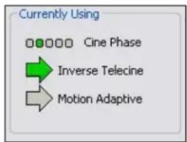
Currently Using group
The Currently Using indicators allow you to see the current algorithm. These are not control buons; they are read-only indicators. They are mainly useful in Auto Mode, to indicate which algorithm – Inverse Telecine or Moon Adapve – is currently being applied. They are also useful in Inverse Telecine mode to show whether telecine content is present and the Inverse Telecine algorithm is being applied.
The mode currently in use is designated with a green arrow (Figure 43). A mode that is possible under current control sengs but not currently in use is marked by a dark grey arrow. A mode that is not available with the current control sengs is designated with a pale outline arrow.
Figure 43. Current Using sengs
With inverse telecine enabled, when telecine content is detected, the ve Cine Phase dots show whether the 3:2 pull-down sequence is shiing. If it is shiing, the green marker shis. This happens in mixed telecine/video content, and also in content that was converted to telecine and then post-edited in the video domain. Whenever a shi happens, there are a few frames that are not deinterlaced. If these shis are frequent, you may have to switch to Moon Adapve deinterlacing for consistent quality.
When the telecine detector locks the rst me in a streaming session, the lemost Cine Phase buon is green. If the telecine sequence is perfectly coherent, the phase never shis. Once it does shi, the absolute phase of the Cine Phase display (which of buons 1 through 5 is green) is not significant – the only significant fact is that phase shis are occurring. When the sequence relocks, all phase buons are equally correct.
Adapve Deinterlace window
Click Adjust (Figure 44) to access the Adapve Deinterlace window (Figure 45) in order to adjust the parameters that control moon adapve deinterlacing.
Note: When the driver is using the Inverse Telecine algorithm, either in Telecine mode or Auto mode, the Adjust sengs have no eect at all, and Test Mode is inoperave.
Figure 44. Adjust buon

Figure 45. Adapve Deinterlace window
![Adaptive Deinterlace Motion Threshold 12 3-Frame Algorithm (more precise) 2-Frame Algorithm (less cpu, less latency) Test Mode Restore Defaults Test mode shows visually which portions of the image are being adaptively deinterlaced, to help you adjust the parameters. In test mode, deinterlaced video displays as bright white or colors. Test mode always exits when you close the dialog. Click [Help] for detailed information. Help Close](/content/2026/05/1059310/images/80105de71876d42040aac68747cc9491b050b1e0e292ab303fdb507b9cf72082.jpg)
The Adapve Deinterlace window has the following controls.
| Moon Threshold | The Moon Threshold slider and edit box adjust the threshold of change of pixels that is judged to be moon. If you enter Test Mode and move the slider to the right, the number of pixels that are considered in moon is greatly reduced. As you move the slider to the le, the number of moon pixels greatly increases unl nearly the enre screen is considered in moon. The recommended default is 12. |
| 3-Frame Algorithm | The 3-frame algorithm detects areas of moon and synthesized adapve pixels for those areas by looking at three frames of video – the current frame, the frame before it, and the frame aer it (the video is pipelinesso that the next frame can be examined before the current frame is released). |
| 2-Frame Algorithm (less CPU) | The 2-frame algorithm refers to just two frames. The 3-frame algorithm results in slightly more accurate deinterlacing but uses slightly more processing power. The 2-frame algorithm is the default because the quality dience is not easy to see.The 3-frame and 2-frame algorithms treat non-moon areas (areas that are not green in Test Mode) the same way, and there should be no loss of detail in sll areas. |
| Test Mode | When you select Test Mode, the moon adapve algorithm displays moon pixels as bright white or colored dots in place of the actual pixels of the image. The dots will mainly be along edges that are in moon. If the moon threshold is set too low, there may also be a random distribuon of bright altered dots caused by pixel jier and instability of the video signal. If the moon threshold is set too high, there will be few or no altered dots, and deinterlacing will be insucient. Test mode is always automacally exited when you close the Adjust window. |
| Restore Defaults | Click Restore Defaults to restore the default sengs. |
Notes:
- When you enable Auto mode, some kinds of content cause the driver to frequently switch between Inverse Telecine and Moon Adapve processing. Content such as tle sequences and commercials are oen telecine, but cuts between scenes generally break the telecine sequence, forcing the driver to resynchronize. It takes it a number of frames to lock on to the new sequence. The driver drops back to the Moon Adapve algorithm as soon as it becomes aware that telecine sync has been lost. However, it may take it several frames to discover that this has happened; these frames are not correctly deinterlaced.
- You should decide whether to use Auto, Inverse Telecine, or Moon Adapve mode depending on the type of content you expect.
° If the content is consistently telecine (pure movie content), then either Auto or Inverse Telecine is recommended for perfect recovery of the original progressive format.
If the content is telecine with post-detelecine video-based eding, Auto mode results in the best overall quality – but several frames may not be deinterlaced every me the pull down phase sequence has to be relocked.
If the content format is a rapidly changing mix of telecine and video, or is all video, or is of unknown type, the Moon Adapve seng gives the most consistent results. (Most broadcast video is of this kind.) The quality of telecine sequences is not the best possible, but there are no instances of frames not deinterlaced at all due to telecine re-locking.
Eects on video latency
Some deinterlacing modes introduce one frame me of latency to the processing of captured video frames. That is, the processing adds 33 msec (525-line, NTSC), or 40 msec (625-line, PAL/SECAM) or delay to the me between end of frame capture, and return to the client. In all cases, this latency is in addition to the me for processing aer capture – which is typically 1 to 5 msec. The one frame of latency is inserted or not inserted as follows:
- If deinterlace mode is 0, there are zero frames of latency.
- If the mode requested is Moon Adapve, and the algorithm selected in the Adjust subdialog is 2-frame, there is one frame of latency.
- If the mode requested is Moon Adapve and the algorithm selected in the Adjust subdialog is 3-frame, there is one frame of latency.
- If the mode requested is Inverse Telecine or Auto, there is one frame of latency. In Auto mode, there is one frame of latency regardless of whether the 2-frame or 3-frame algorithm is selected for Moon Adapve fallback.
Video processing latency does not act most applicaons. For applicaons where it is important to reduce latency, the single most important step is to set deinterlacing mode wither to O or to Moon Adapve - 2 frame. Other factors to reduce processing me are the following:
- Set Deinterlacing to O rather than Moon Adapve – 2-frame – for absolute minimum processing me.
- Set gamma correcon to the default, 100.
- For SECAM video, set the hue adjustment to the default, zero.
• For 525-line (NTSC) video, either: - set Square Pizel (640 x 480) reference size, and capture full sized, 640 x 480 video; or
- set CCIR (720 x 480) reference size, set Source Width to 720, and capture full sized, 720 x 480 video
- For 625-line (PAL/SECAM) video, set CCIR (720 x 576) reference size, set Source Width to 720, and capture full sized, 720 x 576 video.
- Set the client applicaon for YUY2 color format.
- Turn o logos and on-video capon rendering.
When all these steps are taken, latency will be 1 msec or less if the capture desnaon buers are in system memory (they will be in system memory except in some direct-render-to-screen applicaons).
When diagnoses are enabled, the latency is shown in a line of the form, "latency per frame msec = 0.8554164," meaning that video frame delay from capture to return to client is 0.85 msec.
Notes:
When you select Auto mode, some kinds of content will cause the driver to frequently switch between Inverse Telecine and Moon Adapve processing. Content such as tie sequences and commercials is oen telecine, but cuts between scenes generally break the telecine sequence, forcing the driver to resynchronize. It takes it a number of frames to lock on to the
new sequence. The driver will drop back to the Moon Adapve algorithm as soon as it becomes aware that telecine sync has been lost. However, it may take it several frames to discover that this has happened; these frames will not be correctly deinterlaced.
If the content is consistently telecine, that is, pure movie content, then either Auto or Inverse Telecine is recommended for perfect recovery of the original progressive format.
If the content is telecine with occasional post-detelecine video-based eding, Auto mode will result in the best overall quality – but there may be several frames that are not deinterlaced every me the pulldown phase sequence has to be relocked.
If the content format is a rapidly changing mix of telecine and video, or is all video, or is of unknown type, the Moon Adapve seng will give the most consistent results. Most broadcast video is of this kind. The quality of telecine sequences will not be the best possible, but there will be no instances of frames not deinterlaced at all due to telecine re-locking.
Device tab
Device controls (Figure 46) are more specialized items. Unless specifically noted, changes made on this page apply to all Iters and all video previews and capture pins on the currently selected device. Unless noted, dierent sengs may be set and stored for dierent devices.
Changes to these controls take eect as soon as you click Apply or OK.
Figure 46. Device tab
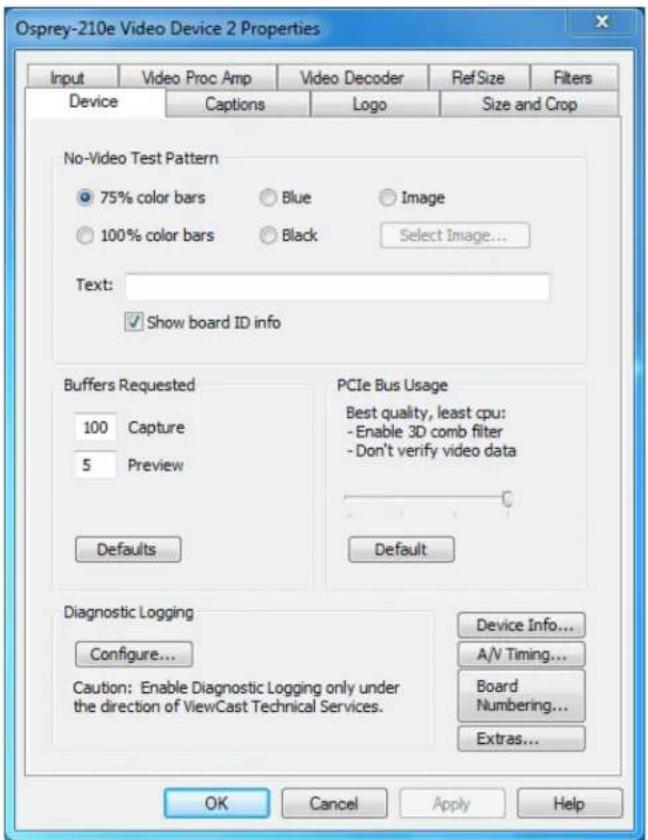
The Device tab has the following controls.
| No-Video Test Paern | This control enables you to select a paern to display when no video signal is present. |
| Buers Requested | The driver indicates the minimum number of video capture buers needed to allocate for proper operaon. |
| PCIe Bus Usage | The driver has adjustments to ensure that the board does not try to capture more video that the system’s PCIe bus can absorb. |
| Diagnosc Logging | For use by Osprey Technical Support Only. |
| Device Info ... | Click this buon to display the Device Info dialog box (see Device Info). |
| A/V Timing | Click this buon to display the Audio/Video Timing dialog box (see A/V Timing). |
| Board Numbering | Click this buon to open a dialog box for renumbering the boards (see Board numbering). |
| Extras ... | Click this buon to display the Extras dialog box (see Extras). |
No-Video Test Paern
The No-Video Test Paern (Figure 47) controls what to display when no video signal is present.
Figure 47. No-Video Test Paern
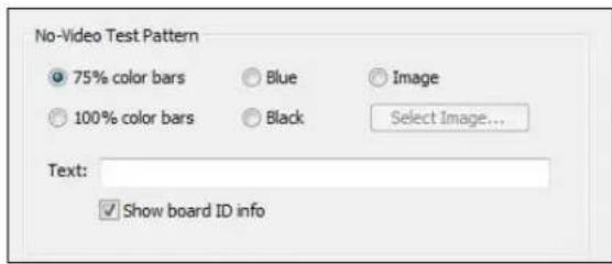
You can select one of the following paerns:
- 75 % color bars
• 100 % color bars - Solid black
- Solid blue
- Image
The 75 % color bars are calibrated to show correct luma and chroma test paerns on a vector scope. The calibraons are slightly dierent for NTSC, NTSC-J, and PAL/SECAM.
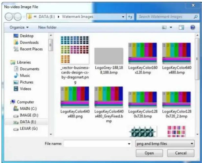
You can also display a PNG or 24-bit BMP image when there is not video signal. The image will stretch or shrink to t the size of the full video reference frame. If you are cropping the video, the crop is applied to the no-video image as well as to the video. Clicking Select Image displays a standard Windows le select sub-dialog box (Figure 48) to select the image. It is customary for BMP les to have a le name extension .bmp and for PNG les to have the extension .png. However, the driver determines the le type by reading the le header.
Figure 48. Selected Image
You can place a text line on the test paern. If the Text edit box is empty - no spaces and no text characters – then no text will exist. Otherwise, whatever you type here, up to 32 characters, displays on the test paern.
Click Show board ID info to display the device name, the currently selected video input, the PCI Express bus and slot number, and the board serial number. This display is useful for determining which physical board in the system corresponds to each device name.
Buers Requested
The driver can tell DirectShow the minimum number of video capture buers it needs to have allocated for proper operaon (Figure 49). The client applicaon may ask for a dierent number of buers; in general DirectShow honors the larger of the requests.
Figure 49. Buers Requested
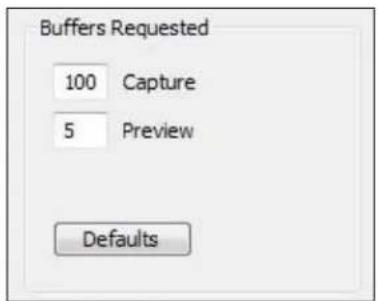
Buers are used in a round-robin style. The driver Ils a buer; the client then consumes the buer, and releases it when it is done. The buer then circulates to the driver to be lled with video again. If the
client holds on to a large number of buers at once, there may be no empty buers available to the driver and frames may be dropped. The soluon is to allocate a larger number of buers.
Capture and encoding applicaons generally need a large number of buers so they can deeply pipeline the downstream processing without danger of buer starvaon at the driver. If buer starvaon is evident, in the form of dropped frames, you can try increasing the number of buers allocated for the Capture pin.
Preview video that is directly rendered on the screen does not use deep pipelining and cannot benefit from it. There has been some evidence that too many buers for direct rendering can harm performance.
- On the Capture pin, increase the number of buers from the default 100 for deeper pipelining and more resistance to dropped frames.
- On the Capture pin, reduce the number of buers to around 5 if the video is going to be used only for direct rendering. Remember to put the number back to 50 or more for capture or encoding to avoid dropped frames.
- On the Preview pin, increase the number of buers to about 7 to 10 if preview video is jerky or irregular.
Click Defaults to return to the default sengs.
PCIe Bus Usage
PCIe system bus implementaons vary in quality and performance. The Osprey Analog PCIe series driver has adjustments (Figure 50 and Figure 51) to ensure the board does not try to capture more video than the system's PCIe bus can absorb.
Figure 50. Osprey 260e PCIe Bus Usage
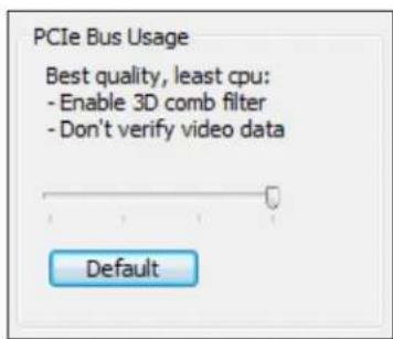
Figure 51. Osprey 460e PCIe Bus Usage
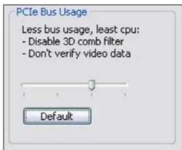
The Osprey Analog PCIe series driver uses three methods to ensure adequate PCIe bandwidth and prevent video data errors:
• Disabling 3D comb Itering
• Vericaon of video data
- EaseStream reduced DMA
Disabling 3D comb Itering
Disabling 3D comb Itering is the most important method to ensure adequate PCIe bandwidth and prevent video data errors.
One of the special features of the Osprey 260e/460e is 3D comb ltering, which improves color separaon and video quality on Composite NTSC and PAL video input, compared to the more common 2D comb ltering. The implementation is hardware based and uses system memory to store frame data needed for the 3D method. This data is both written from the card to system memory and then read back into the card; both these steps consume significant PCIe bandwidth.
Osprey 260e
Each device occupies a separate PCIe X1 lane. It is not likely that you will have any problems using 3D comb ltering all the me, even when mulple cards are installed in the system. Therefore the default seng for the Osprey 260e is for 3D comb ltering to be turned on (Figure 50).
Osprey 460e
All four channels on one board use the same PCIe X1 lane. While it is possible to run two of three video streams on a PCIe 1.X system with 3D comb Itering turned on, the PCIe bus may be overloaded by three or four streams on these systems.
The default seng for the Osprey 460e (Figure 51) is for 3D comb Itering to be disabled. If the bus is overloaded by 3D comb Itering, the eects on the video are severe – the video will be streaked and torn, and it will be obvious that something is wrong. However, systems vary and it is worth trying the 3D comb Iter to see it if will work reliably in your scenario.
PCIe 2.0 systems now entering the market have twice the PCIe bandwidth per lane of the older PCIe versions. It is hoped that PCIe 2.0 will make 3D comb iterating much more widely usable on the Osprey 460e card.
Note: When 3D comb Itering is disabled, 2D comb Itering is enabled, so the video connues to be good quality. The dierence between 2D and 3D comb Itering is subtle – to see the dierence clearly you may have to capture individual freeze frames and look at them side by side.
Comb Itering is only meaningful for Composite NTSC and PAL inputs. It has no funcon for SECAM video. It has no funcon for Component (YPrPb) video or for S-Video. In these cases it is turned o automacally. You can therefore leave 3D comb Itering enabled while using SECAM, YPrPb, or S-Video, without incurring an unnecessary PCIe bus usage penalty.
Vericaon of video data
Vericaon of video data is less likely to be needed than the comb Iter control. When this facility is enabled, the driver detects and corrects certain types of PCIe errors in the video. Turning on this facility increases the amount of CPU me used by the driver. The amount of the increase would only be a problem on slower or heavily loaded systems. Because the impact varies from system to system, we suggest you use the system Task Manager's Performance Meter to see the eect on your specific system.
EaseStream
EaseStream is not normally needed. EaseStream reduces horizontal video capture resolution by half, which may solve extreme PCIe bandwidth problems. If the output capture size is CIF (half-sized) the reduce in quality is not noceable. But with full sized video output, you would noce a significant loss of video quality.
Sengs details
The bus usage control opons are organized into four steps controlled by the slider in this control group.
Figure 50 and Figure 51 shows the default seng. At this seng, 3D comb ltering is disabled and video data vericaon and EaseStream are turned o. The default buon returns the seng to this posion at any me.
The lemost posion (Figure 52 and Figure 53) combines all three PCIe quality strategies: 3D comb ltering is disabled and video data vericaon and EaseStream are turned on. You should rarely, if ever, need this seng. It results in acceptable half-frame (CIF) capture but should be avoided for full-frame capture.
Figure 52. Osprey 260e Lemost posion
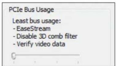
Figure 53. Osprey 460e Lemost posion
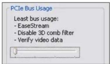
The third posion (Figure 54 and Figure 55) disables 3D comb Itering and turns on video data vericaon, but turns o EaseStream. We have not seen any need for this seng yet in the systems we have tested so far. Use this seng when intermittent horizontal streaks appear in the video, especially when a lot of video streams are running.
Figure 54. Osprey 260e Third posion
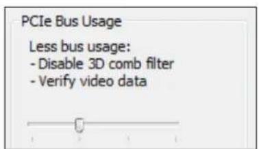
Figure 55. Osprey 460e Third posion

The rightmost posion (Figure 56 and Figure 57) is for systems with high PCIe bandwidth, and especially for PCIe 2.0 systems. It disables video data vericaon and EaseStream and turns on 3D Itering. The warning message only appears for Osprey 260e/460e boards and should not discourage you from trying this seng, but ensures you understand that problems are likely on PCIe 1.X systems when mulple video streams are run.
Osprey Analog PCIe Series User Guide
This control is global – changing the seng in the property page of any channel changes the settings for all Osprey Analog PCIe series cards and channels.
Figure 56. Osprey 260e Rightmost posion
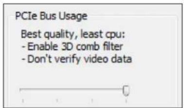
Figure 57. Osprey 460e Rightmost posion
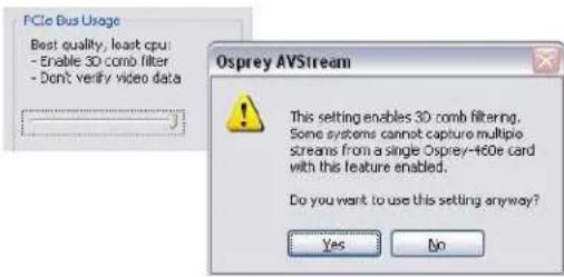
Diagnosc logging
Figure 58. Diagnosc Logging
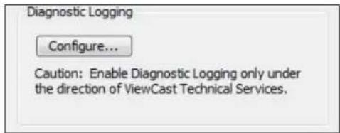
If you contact Osprey Support about a problem, they may request that you provide a diagnosc log from the system that is showing the problem. This control group sets up logging. Diagnoscs logs can be written directly to a le you specify, as well as to the standard kernel driver debug stream. The direct to le opon is usually more convenient.
When you click Congure, the Diagnosc dialog box displays (Figure 59).
Figure 59. Diagnosc Logging
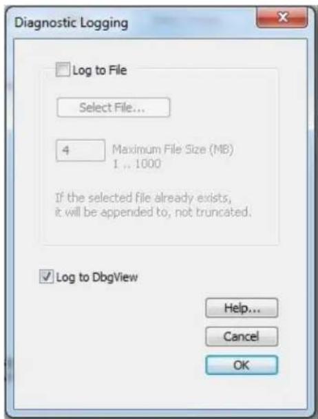
The Log to File check box enables wring diagnoses directly to a le.
Select a directory and le name to complete the setup. For this purpose, when you click Select File a standard Windows select sub-dialog box displays. If you do not select a le, the default is c:\dialog888-1.log. If you select a le that already exists, that le will be appended.
You can specify the maximum size that this le is allowed to grow to. The number in the dialog is this size in megabytes. The allowed range is 1 MB to 1000 MB (1 GB). If the le increases to the size you have specied, data already wrien is retained, but no new data will be wrien.
The Log to DbgView check box enables wring diagnoses to the standard kernel driver debug stream, which can be captured and displayed by ulies such as DbgView. DbgView is a Microso ulity that you can download from MSDN (search for DbgView download). Direct-to-le logging is usually easier, so you will probably not need this opon.
The data collected includes the stream conguraon of each Osprey Analog PCIe series audio and video stream, each stream's stascs at the end of the run, and all run state changes of all streams. A typical secon of data is depicted in (Figure 60).
Figure 60. Data collecon sample
v- 2011/04/27 14:35:14.765: o260 video channel 3 filter 1 preview pin 1: pause->run video cap,pre running = 1,1
v- 2011/04/27 14:35:14.765: o260 video channel 3 filter 1 cc pin 1: pause->run video cap,pre running = 1,1
a- 2011/04/27 14:35:23.343: o260 audio channel 3 pin 1: run->pause audio cap running = 0

v- 2011/04/27 14:35:23.343: o260 video channel 3 filter 1 capture pin 1:

v- device level configuration:
v- OS = W7 64-bit
v- driver version = 4.6.2.0 board type = 51 (33h)
v- input line: type = composite instance = 0
v- video standard = NTSC-M
v- reference size: mode = square pixel process wss = no
v- ntsc lines: top = 23 number of lines = 480
v- simulstream: enabled, licensed mode, number of filters = 1
v- deinterlace mode = adaptive
v- proc amp:
v- brightness = 100 contrast = 100
v- saturation = 100 hue = 0
v- gamma = 80 sharpness = 2
v- dma control: easestream = no underrun = no 2Dcomb = no
v- registry settings:
v- driver 'Config' dword = 084A4000h
v- device 'Config' dword = 01000348h

v- pin level configuration:
v- color format = rgb32 inverted
v- output height = 240 output width = 320 output stride = 320
v- crop top = 0 bottom = 480 left = 0 right = 640
v- frame rate requested = 29.97 frame interval requested 10M = 333667
v- 24 fps locked = no
v- clock type = avstream master
v- number of buffers requested = 100

v- pin level stats:
v- duration of capture session 10M = 81749682
v- actual minus expected duration 10M = 1267
v- actual frame rate fps = 29.9695|
v- actual frame interval 10M = 333672.171
v- avg cpu per frame 10M = 75093.869
v- client buffer type = fast

v- frame count current = 243 cumulative = 825
v- drop count current = 2 cumulative = 2
v- no video signal current = 66 cumulative = 66
v- processing overruns current = 0 cumulative = 0
v- client no buffers current = 0 cumulative = 0
v- audio restarts current = 0 cumulative = 0

v- device level stats:
v- number of dmas = 244
v- dma interval, average 10M = 336411.716
A detailed explanaon of how to interpret this data is beyond the scope of this document. Osprey normally supports interpretaon of diagnosc logs only in reference to speci issues raised with Osprey support. The meaning of many of the log entries will be evident to an experienced user, though.
This control is global to all Osprey Analog PCIe series audio and video devices and streams.
Device Info
Figure 61. Device Info
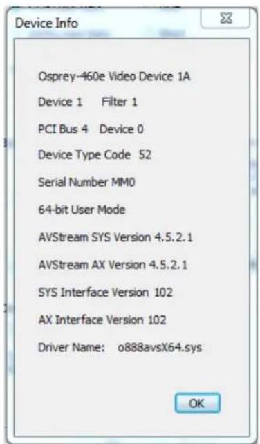
The Device Info window (Figure 61) displays useful informaon about the capture card and the driver:
- DirectShow name of the device
• Device and Iter number
• PCI bus and slot numbers of the device - Device type code
- Serial number of the device
• Whether the applicaon is 32-bit or 64-bit - Versions of the kernel driver and user mode DLL (AX)
- Versions of the interfaces between the kernel driver and user mode DLL
- File name of the kernel driver binary
Click OK to close the window.
A/V Timing
The Audio/Video Timing dialog box (Figure 62) controls audio/video (A/V) synchronizaon and mestamps. (Osprey 100e: Flash/Click A/V Sync Test control does not display and Audio references do not display.) Changes take eect on a given device aer all audio and video streams on that device have been stopped.
Figure 62. Audio/Video Timing
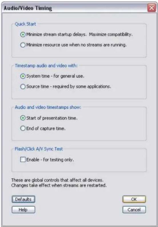
Quick Start
In the absence of Quick Start, video capture on the Osprey Analog PCIe series cards takes about 350 to 400 msec to start up when a channel's rst stream is started. When you enable the Quick Start opon (Figure 63), the startup delay is reduced to between 5 to 50 msec. Audio startup is reduced from about 100 msec to the same range – 5 to 50 msec.
Figure 63. Quick Start
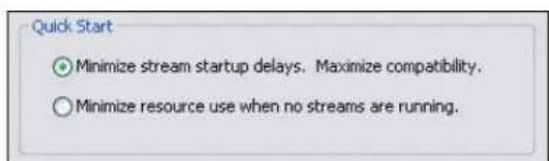
The Quick Start opon also causes the rst audio buer and video frame to be delivered at close to the same me. This fact is important to some applicaons. Most mainstream applicaons determine correct
sync from mestamps, and are therefore immune to dierences between audio and video startup mes. But some applicaons do not do this correctly, and for correct initial A/V sync theQuick Start opon must be enabled.
Another advantage of Quick Start is relevant for SimulStream users. If Quick Start is disabled, the startup ming for the rst A/V stream pair to start is dierent from the ming for subsequent stream pairs. When Quick Start is enabled, the startup ming of all A/V stream pairs is about the same.
The Quick Start opon avoids startup delays by running video and audio capture in the background at all mes, and discarding the results when they are not needed. This opon consumes some system resources – in particular, PCIe to system memory bandwidth. The driver avoids processing the captured audio and video, so processor ulizaon remains low.
When Quick Start is enabled, audio and video internal capture has to be restarted when some sengs change. Audio must be internally restarted when the audio capture sampling rate (32 K, 44.1 K, or 48 K) is changed. Video must be internally restarted when the NTSC/PAL video standard is changed, or when any of several frame geometry parameters is changed. The driver performs these restarts as soon as it can, but in some cases the rst startup aer a sengs change may not be a Quick Start.
Timestamp audio and video width
Figure 64. Timestamp audio and video width
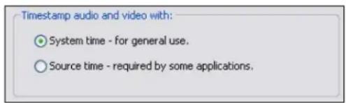
Capture drivers mark audio buers and video frames with mestamps that the client applicaon uses to align the audio and video streams for correct A/V sync. Timestamps are most commonly derived from the system's me base.
The system me base used for mestamps does not exactly correspond to the incoming video rate. The incoming video rate will be close to 33.3666666... msec per frame for 525-line video (see Note below), and 40.0000 msec per frame for 625-line video. But the system clock will never be exactly at this rate. Furthermore, PC system clocks usually are not accurate – and usually are less accurate than the ming of the video signal.
These discrepancies do not cause problems for most encoders and players – they maintain correct A/V sync regardless of how the me base is scaled.
Some clients, however, require that both the audio and video streams be marked with the exact mestamps implicit in the audio and video sources. That is, audio, which the driver returns in 10-msec blocks, must be marked with successive mestamps that increment in exact 10.0000 msec increments. Video frames must be marked with successive mestamps that increment at exact 33.3666666... or 40.0000 msec increments. This marking is referred to as source-driven mestamping. The Source me eld enables source-driven mestamping (Figure 64).
Source-driven mestamps require audio and video rates to be locked together in an exact rao. The Osprey Analog PCIe series cards provide hardware rate locking that ensures this locking is done.
Source-driven mestamps are enabled only when the audio Iter is a WDM Streaming Capture Filter. Source-driven mestamps cannot be used with legacy Audio Source Filters, because the system sets
their mestamps, and the system always uses system ming. The driver automacally disables source-driven mestamps for both audio and video when it detects an Audio Source Filter in the liter graph. Since this disabling is automac, you can set Source me even if you are not sure what kind of audio liter will be used – the worst that can happen is that mestamping will fall back to system me.
All applicaons that normally use system mestamps will run correctly with source-driven mestamps. Therefore, if you are running mulple simultaneous streams, and some but not all of these require source-driven mestamps, then the global control should be set for source-driven mestamps.
Notes for 525-line (NTSC, PAL-M) video users:
The exact denion of the frame rate for 525-line video is (30 / 1.001) frames per second. This works out to a frame interval that is not exactly 33.3667msec – the nominal value commonly used by Microso convenon – but is really 33.3666666... msec, with the trailing '6' innitely repeang. The discrepancy between these two numbers is about 2.5 video frames per day. The Osprey Analog PCIe series hardware rate locking converges audio and video to the correct and exact 33.3666666... msec rate. The driver's source-driven mestamps increment in a sequence (33.3666 – 33.3667 – 33.3667 msec) such that the cumulave me also converges correctly to the exact 33.3666666... msec rate. Currently, no applicaon specially requires the nominal 33.3667 msec rate rather than the exact 33.3666666... msec rate, but the driver has a registry control to enable the nominal rate – contact Osprey Support if you encounter this issue.
The exact frame intervals – such as 33.3666666... msec rather than 33.3667msec – are used only when the client applicaon species a frame rate at or close to one of the following: 30 or 29.97, 24 or 23.976, 15 or 14.985, or 10 or 9.99. When (and only when) source-driven mestamps are enabled, the driver will snap any of these rates to the closest exact rate. When the client applicaon species any other video frame rate, the driver will not perform a snap-to funcon and will deliver frames at the exact rate specified by the client.
None of these issues arise with 625-line (PAL, SECAM) video. The full-rate frame interval is always exactly 40.0000 msec and no snap-to funcon is required.
Presentaon Time Adjustment
Figure 65. Audio and video mestamps show
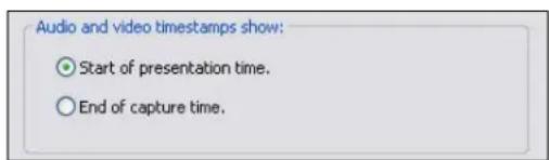
Mulmedia capture drivers most oen mark each frame and buer with the me of the end of its capture. Encoders and players, on the other hand, work in terms of the “presentaon me” of media samples, which is the beginning of the interval when each media sample should be played. Since audio and video samples are of dierent lengths (10 msec for audio, versus 33 or 40 msec for full-rate video), the way mestamps are interpreted aects the A/V sync relationship of the two streams. Although encoders and players could in theory assume that the capture driver is marking the ends of capture intervals, and translate the mestamps to presentaon me format, it appears that they do not generally do so.
The Start of presentaon me opon tells the driver to perform this translaon. Windows Media Encoder provides a ghter A/V sync with this opon, especially in conjuncon with the Silverlight Player.
The End of capture me opon tells the driver to not perform any translaon, and to return mestamps that mark the ends of media samples.
The adjustment consists of shiing video slightly earlier relave to audio. The shift is small – ranging from 23 msec for full rate NTSC to 50 msec for half rate PAL. It is noceable to many video professionals, but for typical end users it is at most a subliminal experience enhancer. Use the Start of presentation me opon unless a specific reason is found not to.
Flash/Click A/V Sync Test
Figure 66. Flash/Click A/V Sync Test
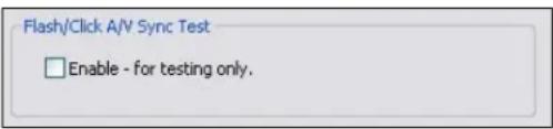
Selecng Flash/Click A/V Sync Test (Figure 66) enables a test mode in which the driver marks audio and video samples at approximately 1.5 second intervals. (This control is not applicable to the Osprey 100e.) The marks are placed on audio buers and video frames captured at exactly the same me, and are used to verify a correct A/V sync. The video mark is a bright red frame; the audio mark is a 1 kHz tone of the same duraon as one video frame interval. When video is captured at half-rate, the video marking interval is 3 seconds rather than 1.5 seconds.
This control is immediate in its eect – sync marks will show up in running streams as soon as the check box is selected. Flash/click test mode remains enabled only as long as the A/V Timing dialog box is opened. It is automatically cancelled when the dialog is closed or you click Default. This seng is not saved from session to session – the dialog box always opens with the ash/click test disabled.
Board numbering
When a system with mulple Osprey boards is rst set up, the device numbers react the order that the system idened and initialized the boards. The driver associates each device number with the PCI address of the board to which it is initially assigned, and saves that informaon. Each me you restart the system the same associaons are preserved.
This initial ordering might not be the order you want. For example, in a system with four boards you may want the boards ordered 1-2-3-4 from le to right or top to boom of the chassis.
Click Board Numbering on the Device tab to display the Board Numbering window (Figure 67) for renumbering the boards.
Figure 67. Board Numbering
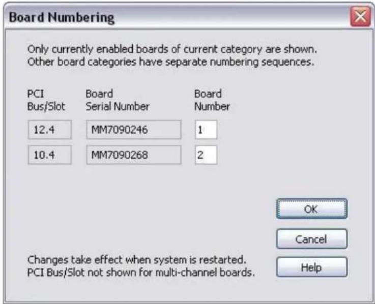
Each line represents the informaon for one Osprey board. Only boards that are currently installed and enabled appear. Also, only boards of one type at a me appear. For example, in a system with two Osprey 260e and two Osprey 460e boards, the two board types are numbered separately. There is a board 1 and a board 2 of each kind. Which lisng is shown depends on the context in which you open the property pages. If you open them from an Osprey 260e context, you see the two Osprey 260e boards. If you open them from an Osprey 460e context, you see the two Osprey 460e boards.
The informaon for each board includes the PCI bus and device address on the le, the serial number in the middle, and the current device number on the right. For boards such as the Osprey 460e which span mulple PCI addresses, the PCI Bus/Slot informaon does not display.
You can edit the device numbers. You can assign each board any number from 1 to 10. All boards in the current list must have dierent numbers. The numbers do not have to be in a packed sequence 1, 2, 3...
The easiest way to identify boards is to start all boards streaming, and remove the video sources so that test paerns like those in Figure 68 display.
Figure 68. Test paerns
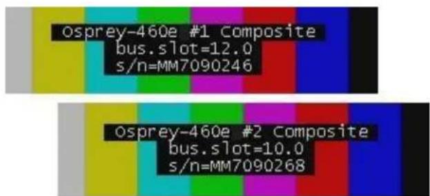
To set up the test paerns, enable the board ID informaon display by enabling Show board ID info on the Device tab (Figure 69).
Figure 69. Show board ID info eld
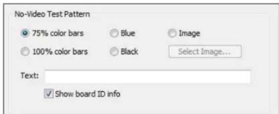
The informaon shown includes the PCI bus and slot for the board, and the board's serial number, in the same format as the Board Numbering dialog.
When you have set the new board numbers and want to save them, click OK. The dialog warns you if the numbers are not in the allowed range 1 to 64, or if there are duplicates – you must correct these issues before saving the numbers and exing. However, click Cancel at any me to exit, and your changes are discarded.
The new numbering takes eect when you restart the system.
Note: Board sengs, especially video custom properes such as Crop, Logo, and Capons sengs, are linked to board PCI addresses rather than to board numbers.
Aer you renumber boards, you may have to re-set your volume levels. On Microsoft Windows XP plaorms, you may also have to re-select your audio inputs.
When you add a new board, especially a board with complex PCIe topology such as an Osprey 460e, the PCI addresses of boards already in the system may be altered. This may cause the driver to renumber boards already in the system. Use the Board Numbering window to set numbers the way you want. You may have to manually adjust board sengs such as video custom properes when boards are added or removed.
Extras
Extras (Figure 70) are features of the AVStream driver that are new, not fully dened, or subject to change. Extras may also include workarounds to apparent DirectShow issues that may be resolved at a future me. Extras should be expected to change more frequently than other aspects of the driver, and may not be shown for all versions of the drivers.
Figure 70. Extras
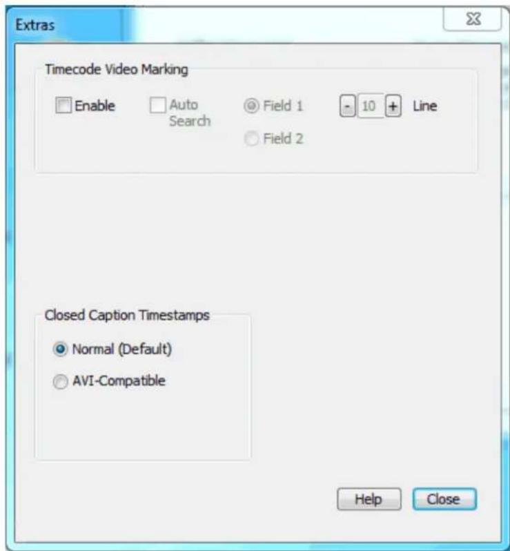
There are currently just two Extras for the Osprey Analog PCIe series cards.
| Timecode Video Marking | Refer to the User Guide for more informaon. |
| Closed Capon Timestamps | This control is a workaround to an apparent problem in DirectShow with capture of CC to AVI les. Always use the Normal seng. |
Captions tab
The Osprey Analog PCIe series driver has four ways of delivering NTSC closed capon (CC) data:
- Renders capons directly on to the video before it leaves the driver
- Sends decoded capon data to a DirectShow-compliant CC pin
- Sends the raw, undecoded Line 21 capon waveform to a DirectShow-compliant VBI pin
- Delivers decoded capon data to a proprietary interface than can be used by C++ developers
The controls on this page pertain mostly to closed capons on video. One control aects closed capon DirectShow pin.
Changes to the controls on the Capons tab (Figure 71) take eect only when you click Apply or OK.
Figure 71. Capons tab
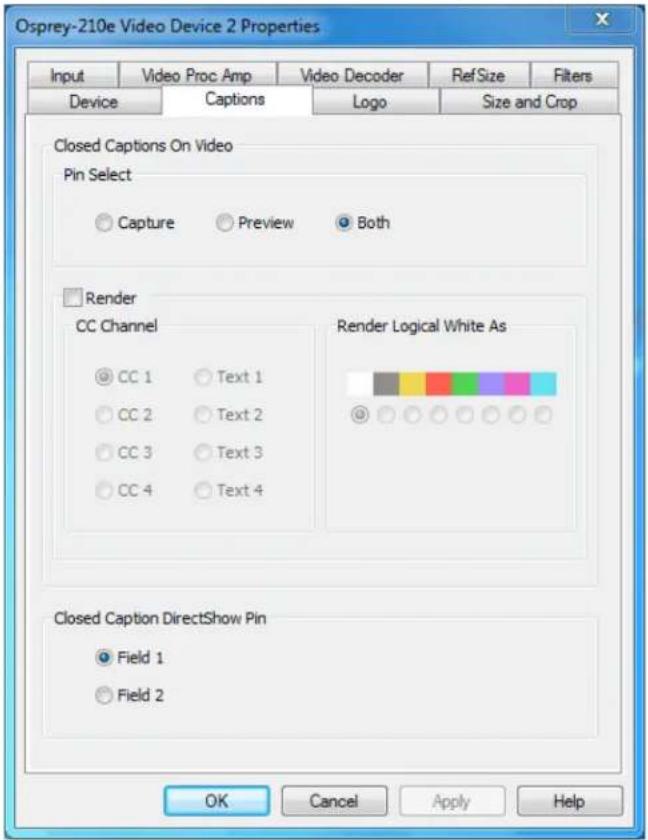
The Capons tab has the following controls.
| Pin Select | The drop-down list has three choices:CapturePreviewBoth |
| Render | The driver can internally render closed capons onto captured video when the video standard is NTSC. |
| Render Logical White as | This control group maps white capons to a color other than white. |
| Closed Capon DirectShow Pin | This group controls whether the closed capon character pairs emied by the DirectShow CC pin are from Field 1 or Field 2 of the video. |
Pin Select
Figure 72. Pin Select
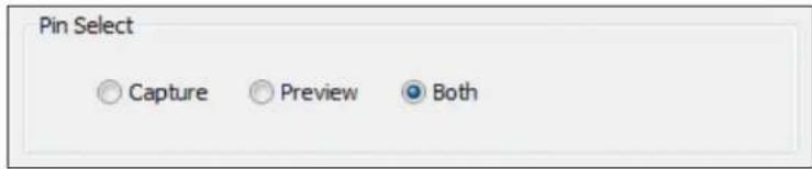
The driver can internally render closed capons onto captured video when the video standard is NTSC. The driver supports the complete EIA-608 closed caponing standard. The 64 additional characters in the EIA-608-B extended character set are also supported.
The Pin Select control (Figure 72) at the top of this control group determines whether changes you make will apply to the capture pin, to the preview pin, or to both:
| Capture | When you click Capture, sengs are shown for the capture pin, and your changes apply to the capture pin. |
| Preview | When you click Preview, sengs are shown for the preview pin, and your changes apply to the preview pin. |
| Both | When you click Both, sengs are shown for the capture pin, but your changes apply to both the capture and preview pins. |
To create dierent sengs for the capture and preview pins:
- Click Capture.
- Congure the capture pin the way you want.
- Click Preview.
- Congure the preview pin the way you want.
- Click Apply or OK.
Note: Click Apply or OK once to apply the settings you have made for both pins.
Render
The Render check box (Figure 73) controls whether or not rendering of closed capons on video is enabled.
Figure 73. Render

CC Channel
When rendering is enabled, the CC Channel control selects which channel to render.
Figure 74. CC Channel
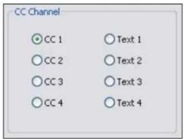
The details of Closed Capon channels are beyond the scope of this descripon – refer to the EIA-608 standards document. But CC 1 is by far the most commonly used channel. Select CC 1 unless you have specific knowledge that you want to render another channel.
Render Logical White As
When rendering is enabled, the control group Render Logical White As (Figure 75) maps white capons to a color other than white.
When rendering is enabled, the control group Render Logical White As can map white capons to a color other than white.
Figure 75. Render Logical White As
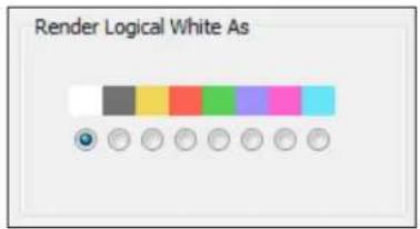
This feature is a proprietary extension by Osprey to the Closed Caponing standard. Nearly all caponing content uses only the default color white. This control causes white capons to appear in the selected color. Capons in other colors are not aected.
Closed Capon DirectShow Pin
Figure 76. CC Pin
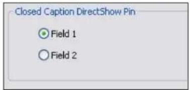
The Closed Capon DirectShow Pin (Figure 76) controls whether the closed capon character pairs emied by the DirectShow CC pin are from Field 1 or Field 2 of the video. The DirectShow specicaon is that CC on a CC pin is always from Field 1; however, this extension allows applicaon developers to access Field 2 data such as XDS data (including V-chip) via a standard DirectShow CC pin.
Logo tab
The logo property superimposes a graphic over captured video using the logo property controls (Figure 77).
Figure 77. Logo tab
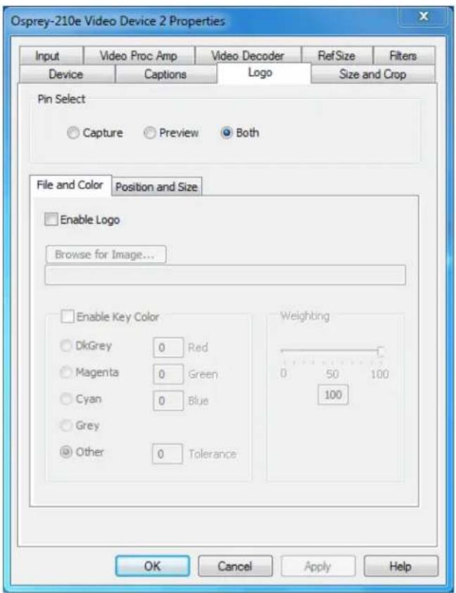
The Logo tab has the following controls.
| Pin Select | The drop-down list has three choices:CapturePreviewBoth |
| Enable Logo on File and Color sub tab | From this control, enable or disable the logo. |
| Enable Key Color on File and Color sub tab | Control the key color and eciency eect. |
| Weighng on File and Color sub tab | Set the degree of transparency of the logo. |
| Posion and Size sub tab | Set the posion of the logo and the scale. |
Logos have the following characteristics:
- Use any RGB-24 bitmap in .bmp le format.
- Use any PNG le.
- For BMP les, and for PNG les without alpha (transparency) data, specify a selectable key color; all parts of the logo graphic with that color are not drawn on the video.
- For PNG les with alpha data, the alpha data determines transparency on a per-pixel basis.
- Use a transparency or weighing control to blend the logo graphic with the background video. You can use this control in combinaon with the alpha data in a PNG le.
• Interacvely posion and scale the logo. - Congure a logo to appear on either or both captured and previewed video.
- The capture and preview streams can have the same or dierent logos. The settings (key color, transparency, size, and posion) of the two logos can be independent or linked. If video sizes of the two streams are dierent, you will usually want to set the size and posion dierently for each logo.
The logo property controls work best when you are already running video that you can directly view, so you can view your changes interactively.
The logo property is organized as two sub-tabs:
- File and Color
- Posion and Size
Pin Select
You can have dierent setups for the two pins. You can enable the logo on the capture pin but not on the preview pin, and thereby save some CPU me.
Figure 78. Pin Select
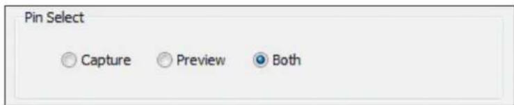
| Capture | When you click Capture, the current logo sengs for the capture pin are loaded, and changes you make apply only to the capture pin, not to the preview pin. |
| Preview | The Preview buon works analogously. |
| Both | When you click Both, changes you make to the logo setup apply to both the capture and preview pins. |
File and Color
Figure 79. File and Color
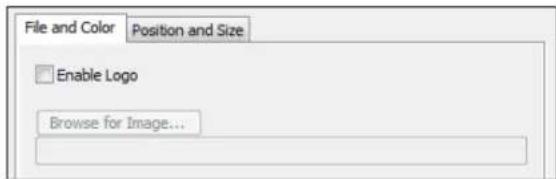
The Enable Logo check box, which is repeated on both sub-tabs, enables or disables logos. If you disable logos, all your other logo sengs are retained for when you re-enable logos.
In Figure 79, clicking Browse for File displays a standard le select dialog. Logo les must be either:
• In BMP 24-bit format
- In PNG format (all commonly used PNG formats are accepted
If you have a graphic in another format, edit it with a drawing or photo edit program such as Windows Paint, and save it as PNG le. The PNG format is recommended instead of the BMP format because it is both compressed lossless – so the image le is smaller, but with no sacrifice of quality. Also, if you use a suitable image editor, you can create transparency eects that are not possible with the BMP format.
Enable Key Color
Figure 80. Enable Key Color
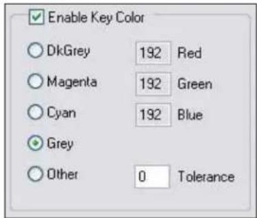
You can control the key color and the transparency eect. If video is running, you see your changes interactively.
You can use these controls with both BMP and PNG images. You can use key colors with PNG images that contain embedded alpha channels, but alpha keying is a superior soluon. If your image editor supports alpha keying, use alpha keying and leave the key color controls disabled. The key color disappears from the graphic so the underlying video shows through unchanged.
If you select Enable Key Color, all colors display.
If you select the check box, key coloring is enabled. The ve radio buons are enabled. You can select one of four standard colors – dark gray, medium gray, cyan, or magenta – or a custom color. If you select Other for a custom color, the three edit boxes – Red, Green, Blue – are enabled, and you can enter any color value in the range 0 to 255 into these boxes.
Figure 81. Tolerance control

Key colors to identify transparent porons of logos can be exact or inexact. The Tolerance control (Figure 81) determines this. If Tolerance is 0, then all key colors have to exactly match the Red / Green / Blue values shown in the key color control group. If Tolerance is nonzero, then the Red / Green / Blue values can deviate from the key color by the tolerance value and sll be treated as being equal to the key color. For example, if Tolerance is set to 5, and the key color is set to grey (192, 192, 192), then pixels in the bitmap with value (187, 187, 187) are also transparent.
Weighng
The degree of weighing of the logo is variable through 100 steps. If the seng is 100, the logo is 100 percent opaque. If the seng is 0, the logo is completely transparent and invisible. If you have set a key color, the weighing or transparency value is applied only to pixels that do not match the key color; key colored pixels are always completely transparent. You can set the weighing either with the slider or by eding the number in the text box (Figure 82).
Figure 82. Weighng
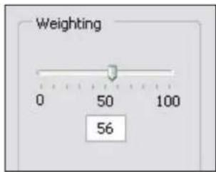
For PNG images with embedded alpha data, the weighing control is combined with the alpha data. For example, if a pixel is weighted 50 percent according to the alpha data, and the weighing control is also set to 50 percent, the pixel displays as 25 percent opaque.
Posion and Size
The Posion and Size sub-tab lets you posion and scale the logo. It is strongly recommended that you have video running when you use these controls, so you can see results interactively.
Figure 83. Logo posion

natural_image
Geometric diagram with a red rectangle and intersecting lines on a green background (no text or symbols)The large green rectangle on this sub-tab represents the video area where the logo can be posioned. The smaller red rectangle represents the logo. To posion the logo, click on the logo rectangle and drag it to the new posion.
If you enable logos, but the red rectangle is not visible, it means that the driver could not nd the logo, or it was in a format other than PNG or 24-bit BMP. Go back to the File and Color page and correct this rst.
The four Nudge buons, (Figure 84) L, R, U, and D, move the logo le, right, up, or down exactly one pixel at a me on the output video. Since the posioning rectangle is scaled down from the full video size, the Nudge buons allow more accurate posioning of the logo.
Figure 84. Nudge buons
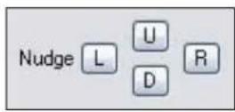
The slide control at the boom right of this sub-tab controls the scaling of the logo. The 1X Scale buon (Figure 85) returns the size to the original size of the .bmp graphic.
If your capture and preview streams have dierent video sizes, you need to view both streams and set the size and posion separately for each.
Figure 85. 1X Scale

Note: Because the Logo tab is used to set up a logo interactively on live video, it behaves dierently from other tabs. The driver updates the controls on the Logo tab immediately, without waiing for you to click Apply.
Size and Crop tab
This tab (Figure 86) has two funcons:
- It sets the default output size, whether or not cropping is enabled.
• It enables and disables cropping, and sets the cropping area.
The default output size is the video size that appears in the DirectShow pin properes dialog as the "default" choice. It is a pathway for seng a custom or nonstandard video size in applicaons that do not have a built-in custom video sizing controls.
Cropping means removal of unwanted video around the edges of the incoming image. For example, if the incoming video is leerboxed, with an aspect rao wider than 4:3, you can crop the black slivers at the top and boom of the image and capture just the acve poron.
Figure 86. Size and Crop tab
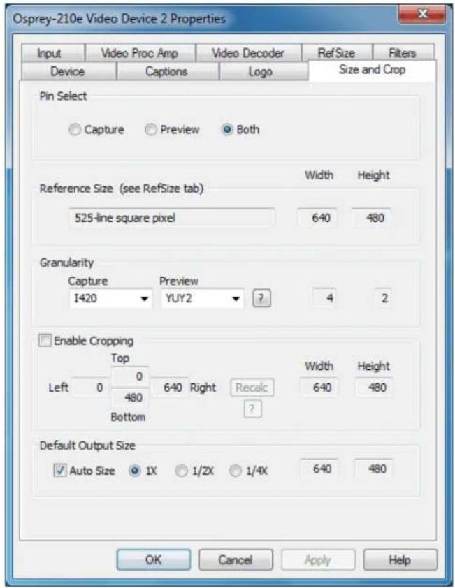
The Size and Crop tab has the following controls.
| Pin Select | This eld has three choices:CapturePreviewBoth |
| Reference Size | Displays the full uncropped size of the incoming video. This read-only informaon is determined by sengs made on the Input tab and the RefSize tab. |
| Granularity | This control helps you choose crop and output sizes that observe those restricons |
| Enable Cropping | When enabled, your video is cropped to the indicated boundaries. When disabled, your video is not cropped regardless of any crop sengs you may have made previously. |
| Default Output Size | Select the height and width of captured video. |
Changes made on this page apply to all video previews and capture pins on the currently selected device.
Pin Select
You can have dierent setups for the two pins. For example, you could enable cropping on the capture pin but not on the preview pin.
| Capture | When you click Capture, the current crop sengs for the capture pin are loaded, and changes you make apply only to the capture pin, not to the preview pin. |
| Preview | The Preview buon works analogously. |
| Both | When you click Both, changes you make to the crop setup apply to both the capture and preview pins. This seng is the default. |
Reference Size
The reference size informaon is always read-only on this tab. It is determined by sengs made on other tabs – specifically, the Input tab, where a 525-line or 625-line standard is selected, and the RefSize tab, where Square Pixel or CCIR proporoning is selected. The read-only text box describes which of these opons is currently governing the reference size.
The reference width and height represent the full uncropped size of the incoming video. Your crop sengs are interpreted relave to this reference size. For example, if you are capturing 525-line video, with a reference size of 640 x 480, and your crop rectangle is (0, 0, 640, 480), then your video is eecvely uncropped. But if you are capturing 625-line video, with a reference size of 768 x 576, the same (0, 0, 640, 480) crop specicaon truncates the right and boom edges of the video.
Granularity
Most video data capture formats impose restricons on the possible width and/or height of the video, referred to as “granularity” restricons. For example, the I420 capture format requires that the capture width be a mulple of 4 and the capture height be a mulple of 2.
The granularies for all products in Post Processing Mode are as follows:
| Format | Horizontal | Vercal |
| RGB32 | 4 | 1 |
| RGB24 | 4 | 1 |
| RGB555 | 4 | 1 |
| Greyscale | 4 | 1 |
| YUY2 | 4 | 1 |
| UYVY | 4 | 1 |
| I420 | 4 | 2 |
| YVU9 | 4 | 4 |
| [none] | 4 | 1 |
| [any] | 4 | 4 |
The Granularity controls show you set restricons for the selected video format, and assist you in choosing crop and output sizes that observe those restricons.
Because the preview and capture pins may be set to dierent color formats, they may have dierent granularies. When the Crop tab is opened, the Capture and Preview elds are initialized to the current or most recently used format for the selected pin.
If your Pin Select setng is Capture, only the Capture granularity box is enabled; similarly for Preview. The two small read-only edit boxes to the right of the group show the horizontal and vercal granularies for the selected color format for the selected pin type.
If your Pin Select setng is Both, both the Capture and Preview elds are enabled, and the two elds to the right of the group show the worst-case granularity that works for both the Capture and Preview color formats. For example, if the Capture color format is I420 and the Preview color format is YUY2, the resultant granularity is I420's more stringent 4 x 2 requirement.
The granularity sengs aect values you subsequently enter for crop width, crop height, and default output width and height – they are adjusted to these granularies. Adjustments are made when you click on another control.
You can change the video format in the drop-down list, so that granularies are set for a dierent format.
Note: This acon does not automacally cause the pin to have this format – you sll have to select that format using the Pin Properes window or via your applicaon. It just ensures the sizes you select work correctly when you do select this color format in the applicaon.
If you set up your crops with a less restrictive granularity (for example, YUY2) and then capture with a more restricted granularity (for example, I420), the driver may automatically adjust the video crop
and/or output size without nofying you. Or, the capture may fail. You may also nd that in the Pin Properes window the default size you wanted is not listed – because it is not a legal size for this format.
If you select None as the color format(s), no granularity adjustments are applied to your crop and size data. In pracce, None is the same as the packed RGB and YUV modes.
If you select Any as the video format, the coarsest granularity required by any of the available formats is applied to your crop and size data. In pracce, Any is the same as YVU9, that is, 4 x 4. You are guaranteed your crop and output sizes will never be adjusted, regardless of what video format you select now or in the future.
There is also a restricon on horizontal placement of a cropping window – the placement must be on an even pixel boundary, 0, 2, 4 ...
Enable Cropping
If you clear Enable Cropping, your video is not cropped regardless of any crop sengs you may previously have made. The edit boxes showing the edges, height, and width of your crop is read-only and shows sengs for full-frame, uncropped video.
Figure 87. Enable Cropping

If you select Enable Cropping, your video is cropped to the indicated boundaries. The edit-boxes are initially set for the full uncropped video frame. The Top and Le boxes set the top le corner of the cropping rectangle. The Right and Boom boxes set the boom right. The Width and Height boxes set the size of the rectangle.
Recalc buon
The Recalc buon recalculates whichever of the crop edit boxes you have not lled in. For example, if you set Top, Le, Width, and Height, Recalc calculates Right and Boom. If you set Top, Le, Right, and Boom, Recalc calculates Width and Height. Whichever of the vercal group was least recently touched, is the item that is recalculated; similarly with the horizontal group. If you have only changed one box of the group, you can force the order of recalculaon by clicking one of the other two boxes. For example: If you changed Le, and you want to preserve Width (but alter Right), then click on Width before Recalc. If you have changed Le, and want to preserve Right (but alter Width), then click on Right before Recalc.
If your specicaon results in a crop rectangle that is too large or too small, Recalc adjusts it appropriately. If it can't set up an allowed size by changing just the third most recently clicked seng, then it tries to change the second most recently clicked seng instead or as well. If it has to, it changes your most recently changed seng.
Recalc also factors in granularity and posioning requirements. The le edge, height, or width value of a crop rectangle may be lowered to the next smaller granularity threshold. This approach is the likely
reason why small adjustments may not take aer Recalc – they are rounded down, so nothing changes. You have to use a value that is larger than the next granularity threshold. See Granularity for the value of the granularity parameters.
In the Default Output Size group, Recalc changes the default output size if Auto Size is enabled. If Auto Size is not enabled, Recalc leaves the output size alone.
Note: The crop width and height are subject to the granularity requirements of the selected video format, as explained in the previous secon. For example, if your video format is 1420 and you try to set a crop width of 360, it gets adjusted down to 352.
If you enable cropping, enter in some custom sengs, and then disable cropping, an uncropped specicaon displays and your sengs disappear from view. However, the driver does remember your custom sengs, and if you enable cropping again, they reappear.
The driver can upscale cropped video, up to the reference size.
Cropping rectangles are frame-based rather than eld-based. Thus if a crop rectangle is set up dening a 320 x 240 area, then a capture of video sized at 320 x 240 results in video being captured from two elds. You may therefore see interlacing artifacts in the captured video, unless a deinterlacing iter is applied. This may be initially confusing since most users typically think of 320 x 240 video captures only coming from a single eld and thus would not have interlaced artifacts. However, in this case, the source video is only 320 x 240 in size (i.e. the crop rectangle) and thus any captured video that is greater than the eld height within the crop rectangle (equal to 12 cropped ROI height) results in a scaled capture of mulple elds. Also, the driver uses both elds whenever they are needed to interpolatively scale the output with best possible accuracy.
Default Output Size
Figure 88. Default Output Size
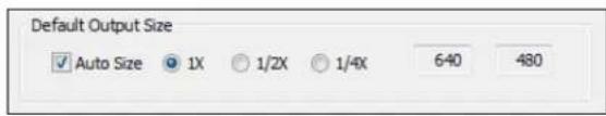
The standard DirectShow Pin Properes dialog allows you to select the height and width of captured video from a drop-down list. The drop-down list has a parcular range of choices that may or may not t your needs. The drop-down list includes one default size that the capture driver provides. The Default Size control allows you to set up what default size appears.
If you select Auto Size, (Figure 88) your default video size is sized automatically to your crop sengs. The three radio buons, 1X, 1/2X, and 1/4X, determine whether the output size is scaled down from the crop size.
Example 1: If you are running standard 640 x 480 NTSC video, and Enable Cropping is not enabled, your crop size is 640 x 480. With Auto Size enabled, and the 1X radio buon enabled, your default size is 640 x 480; with 1/2X, 320 x 240; and with 1/4X, 160 x 120.
Example 2: If you have enabled cropping with size 320 x 240 (one quarter of the full video area), the default Auto Sizes are as follows: 1X, 320 x 240; 1/2X, 160 x 120; 1/4X, 80 x 60.
If you clear Auto Size, the default size radio buons are disabled and the height and width edit boxes are enabled. You can set any default size with the following two restricons:
- Since the driver does not upscale video, the default size must be smaller than the crop size. For example, if the crop size is 320 x 240, you cannot set default output size 400 x 300.
- Sizes are subject to the granularity requirements of the selected video format, as explained in the Granularity secon above. For example, if your video format is 1420 and you try to set a default width of 360, it gets adjusted down to 352 as soon as you click on another control
Note: The Pin Properes dialog default entry does not appear in the default VFW/DirectShow mapper dialog. Thus, unless a VFW applicaon, like Virtual Dub, specifically allows for custom resoluons, the VFW app is only able to select from the opons the VFW/DirectShow mapper lists.
Filters, Pins, and Properties
DirectShow technology uses terms with specific meanings. For example, Iter, pin, driver and device appear frequently when discussing DirectShow media standards. Figure 89 depicts the relationship of DirectShow terms as they apply to Osprey hardware and drivers.
Figure 89. DirectShow

flowchart
graph TD
    A["SimulStrm Video Filter 1B"] --> B["Capture Pin"]
    A --> C["Preview Pin"]
    D["SimulStrm Video Filter 1A"] --> E["Audio Filter 1"]
    E --> F["Video Filter 2"]
    F --> G["Audio Filter 2"]
    H["Video Device 1"] --> I["Audio Device 1"]
    J["Video Device 2"] --> K["Audio Device 2"]
    L["Osprey AVStream Driver"] --> M["Osprey Physical Device 1"]
    N["Osprey Physical Device 2"] --> O["Osprey Physical Device 2"]
At the boom of this diagram are one or more physical Osprey hardware devices. For each physical device the AVStream driver creates one logical Video Device and one logical Audio Device.
On top of each Osprey logical Video Device, one or more Video Filters is created. If the SimulStream opon is not installed, each Video Device has a single Video Filter. If SimulStream is installed, each Video Device can have mulple Video Filters. The SimulStream opon is not available for the Osprey 100e.
The disncon between Device and Filter is important mainly to SimulStream users. For non-SimulStream users, Device and Filter eecvely mean about the same thing. For SimulStream users, each SimulStream Filter acts as a virtual device that can have its own independent control sengs.
When you enable SimulStream, some funcons and capabilities are device-level, and others are iter-level. Examples of device-level funcons are input select, and the controls for brightness, contrast, hue, saturaon, and sharpness. These are closely ed to the underlying hardware of the device, which inherently allows only one input to be selected at a me, and one set of hardware control sengs to be applied. Examples of Iter-level funcons are crop, logo, and capon sengs, which can be dierent for each video Iter, and in fact for each pin of each Iter. Some other capabilities such as deinterlace and soware gamma correcon could logically be either device-level or Iter-level, but are treated as device-level for praccal reasons.
Each Video Filter has one Capture Pin and one Preview Pin. A pin is the source or desnaon of a video or audio stream. A video capture pin is a general purpose pin used for capture to a le, an encoder, an
Filters, Pins, and Properes
on-screen renderer, or any other desnaon. A video preview pin is mainly intended for on-screen rendering. Each Osprey Video Filter also has a Closed Capon pin and a Vercal Blanking Interval (VBI) pin for capture of specialized ancillary data.
On top of each Osprey logical Audio Device, one Audio Filter is created, with one or more pins capable of sourcing one or more audio streams. There is not much praccal disncon between an Audio Device and an Audio Filter in either the SimulStream or non-SimulStream cases.
Both devices, Iters, and pins may have associated Properes. Properes are control parameters that can be read from or written to the component. Some Property Pages are standard Windows DirectShow pages. For example, the Property Page for an individual pin is a standard DirectShow page. The Video Proc Amp and Video Decoder Pages are also DirectShow-standard. The rest are proprietary to the Osprey driver.
As a user, you interact with Property through visual Property Sheets, Property Pages, or Property Tabs that are part of a tabbed dialog. As a programmer, you can set properes directly from within the code of your applicaon, using either the standard DirectShow API or the custom Osprey extension API that is available from Osprey in a soware development kit (SDK).
Post-Processing mode
The Osprey Analog PCIe series driver does more than move video data from the hardware to the system. Its Post-Processing facility includes a variety of Iters, transforms, and renderers within the driver, and supports the SimulStream opon.
Figure 90. Post-Processing mode
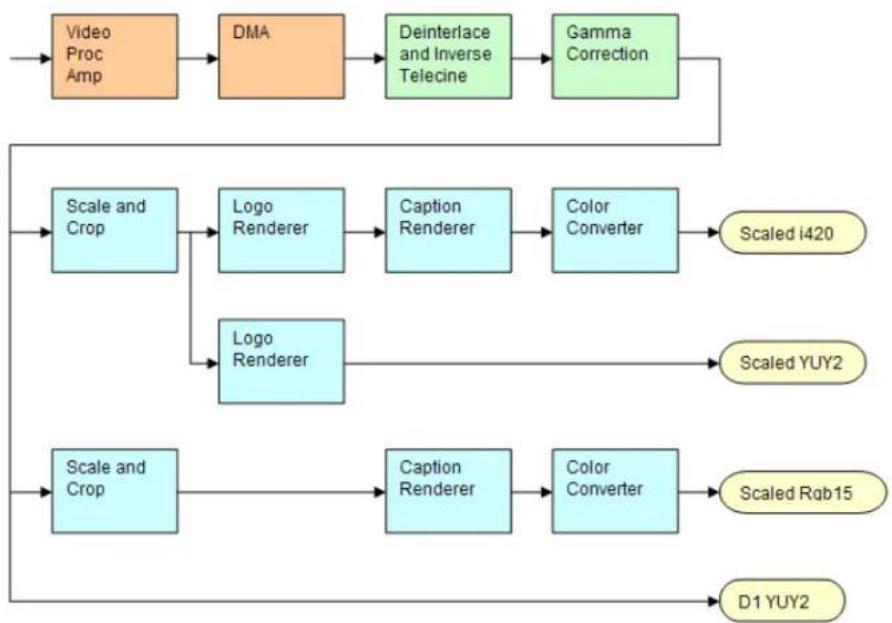
flowchart
graph TD
    A["Video Proc Amp"] --> B["DMA"]
    B --> C["Deinterlace and Inverse Telecine"]
    C --> D["Gamma Correction"]
    D --> E["Scale and Crop"]
    E --> F["Logo Renderer"]
    F --> G["Caption Renderer"]
    G --> H["Color Converter"]
    H --> I["Scaled i420"]
    E --> J["Logo Renderer"]
    J --> K["Scale and Crop"]
    K --> L["Caption Renderer"]
    L --> M["Color Converter"]
    M --> N["Scaled Rqb15"]
    K --> O["D1 YUY2"]
Figure 90 assumes that SimulStream is acvated (SimulStream is not available for the Osprey 100e) so that more than two video pins are possible. In this case, there are four video output pins, represented by the rounded rectangles:
- The upper pin produces scaled and/or cropped I420 video, with a logo (watermark) and NTSC Closed Capons rendered on the video.
- The second pin produces scaled and/or cropped YUY2 video with a logo but no caponing. In this particular graph, the upper two pins are scaled and cropping idencally, so a single scaling operaon can service both pins.
- The third pin has a different scale/crop specicaon, so its video runs through a separate scaler/cropper. The video is caponed and converted to Rgb15.
• The lower pin produces unscaled, uncropped D1 YUY2 video with no logo or caponing.
The video routed to all pins is in this example deinterlaced and gamma-corrected. Deinterlace or inverse telecine if used are always applied globally to all pins, as is gamma correcon. Scaling, cropping, logoing, caponing, and color format conversion are performed separately for each pin.
Post-processing mode has the following capabilities:
- With SimulStream disabled, there is sll a maximum of one capture pin and one preview pin on the device at a me. However, there are no restricons on combinaons of video size
and rate, color formats, or crop sengs. The driver color converts and copies video as required to deliver up to 25 or 29.97 frames per second in any format to the two pins.
- With SimulStream enabled, there can be mulple capture pins and mulple preview pins. Each capture and preview pin pair is placed on a separate Iter. The maximum number of each type of pin is the same as the maximum number of Iters you have elected to expose in the SimulStream control group. Any pin can produce video at any size, rate, color format, and crop seng. Of course, praccal limits are imposed by the bandwidth of the machine.
- The following post-processing Iters can be applied, with or without SimulStream enabled:
° Moon adapve deinterlacing and inverse telecine
° Gamma correcon
° Logos
° On-video capon rendering
Some of these Iters operate globally on all Iters and pins of a device, and some operate on a per-Iter or per-pin basis:
- The Video Proc Amp controls – brightness, contrast, hue, saturaon, and sharpness – are applied globally in hardware to the incoming video.
- The basic reference size – CCIR–601 or square pixel – is established in hardware. Horizontal delay and the 720/704 width select are also performed in hardware.
- Deinterlace / inverse telecine and gamma correcon are applied to all Iters and pins on the device and have the same sengs for all Iters and pins.
- Crop, logo, and capon settings can be dierent for each pin of each iter, and the driver maintains separate sengs for each iter and pin.
- Video size, color format, and frame rate can also be different for each pin. It is the responsibility of the applicaon to maintain these sengs.
Efficient Video Rendering
The following informaon is primarily useful to developers, but may also be helpful for those who want to ne-tune exisng applicaons. If you are seeing poor rendering performance, in terms of either excessive CPU ulizaon or jerky, stuering video, read this secon. The gures in this secon are examples only.
There are at least four basic ways to render video from the capture driver onto the screen. They vary greatly in their eciency, and applicaons do not always make the best choice of renderer.
In these descripons it is assumed that the AVStream driver's Preview Pin is being used. The results would be the same if the Capture Pin were used instead.
Preview Pin to Video Renderer
Figure 91. Video Renderer
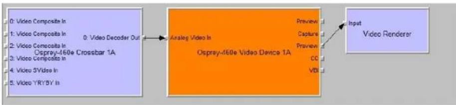
flowchart
graph LR
    A["Input Video Renderer"] --> B["Analog Video In"]
    B --> C["Video Decoder Out"]
    C --> D["Video Composita In: 0: Video Decoder Out"]
    D --> E["Video Composita In: 1: Video Composita In"]
    E --> F["Video Composita In: 2: Video Composita In"]
    F --> G["Ospray-460e Crossbar 1A"]
    G --> H["Video Composita In: 3: Video Composita In"]
    H --> I["Video 5Video In: 4: Video 5Video In"]
    I --> J["Video YRY5Y In: 5: Video YRY5Y In"]
    B --> K["Preview"]
    B --> L["Capture"]
    B --> M["Preview"]
    B --> N["CC"]
    B --> O["VBI"]
Video Renderer is the oldest and simplest DirectShow renderer. It does not use DirectDraw in the rendering process, which makes it substanally slower than VMR7 described below. It is the default rendering pathway that is chosen when an applicaon says Render without specifying a preferred pathway. For this reason, many applicaons deliver unnecessarily slow rendering performance.
Video Renderer works best when your output format is RGB rather than YUV, with the RGB format matched to your screen depth. On most modern systems that means RGB32 is the preferred format. If a YUV format is used, an extra Iter, AVI Decompressor, will be inserted into the graph to convert the YUV to RGB. The driver can do this conversion faster internally.
The best video format to use with Overlay Mixer is YUY2.
Filters, Pins, and Properes
Preview Pin to VMR7
Figure 92. Video Mixing Renderer 7
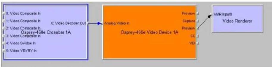
flowchart
graph LR
    A["0: Video Composite In\n1: Video Composite In\n2: Video Composite In\n3: Video Composite In\n4: Video GVideo In\n5: Video YR/YB IN"] --> B["Analog Video In\nOsprey-460e Video Device 1A"]
    B --> C["Preview\nCapture\nPreview\nCC\nVBR"]
    C --> D["VMR Input0\nVideo Renderer"]
VMR7 is short for Video Mixing Renderer 7. VMR7 is a newer renderer that is generally much faster than the old Video Renderer. When the driver is running in Direct Mode, VMR7 uses an ecient DirectDraw conguraon to render with almost no CPU overhead, especially when YUY2 video is used. When the driver is running in PostProcessing Mode, DirectDraw is not used but it is sll the fastest renderer.
Unfortunately, VMR7 is not the default video renderer in building a ltergraph – an applicaon must explicitly ask for VMR7 in its graph for it to be used. This causes many simpler applicaons to render video much less eciently than they might.
VMR7 works best with YUY2 video and there is usually lile reason to use any other format. It will, however, work fairly well with the RGB format – usually RGB32 – that matches the current screen depth. We recommend leng DirectShow choose the video format. It generally makes the correct choice. In parcular, on some (usually older) systems, if two video frames are to be rendered with VMR7 at the same me, only one can be YUY2; other(s) are RGB, with a conversion Iter inserted into the graph if necessary.
We do not provide an RGB24 opon on the preview pin for use with 24-bit screens because on at least some display adapters the rendering of RGB24 to VMR7 is incorrect.
Note: VMR7 cannot be used when closed capons are to be rendered from the driver's DShow-standard CC or VBI pin – use the Overlay Mixer to Video Renderer pathway instead. If the driver's internal rendering is used, the VMR7 works and is recommended.
Preview Pin to VMR9
Figure 93. Video Mixing Renderer 9
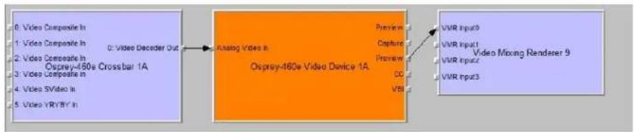
flowchart
graph LR
    A["0: Video Composite In"] --> B["Analog Video in Osprey-460e Video Device 1A"]
    B --> C["Preview"]
    B --> D["Capture"]
    B --> E["Preview"]
    B --> F["DC"]
    B --> G["VBI"]
    H["0: Video Decoder Out"] --> B
    I["VMR Input0"] --> B
    J["VMR Input1"] --> B
    K["VMR Input2"] --> B
    L["VMR Input3"] --> B
    M["Video Mixing Renderer 9"] --> B
Video Mixing Renderer 9 is the newest video rendering method and the one on which Microso supposedly is basing its future development. The intent is to combine the funconality of the Overlay Mixer plus Video Renderer in one module that takes advantage of the latest developments in DirectShow. We are nding that at its present stage of development, with our hardware, VMR9 does not achieve the high eciency of YUY2-to-VMR7. Also, although VMR9 is supposed to funcon as an overlay mixer for rendering caponing from the driver's DShow CC or VBI pin, we have never seen it funcon correctly.
Some Data Points
The following measurements are CPU percent on two machines – a fairly old P4, and a dual Opteron 244. The video size is 640 x 480. The screen depth is 32 bits. The following abbreviations are used:
| YUY2 | the Osprey driver's preview pin in YUY2 format |
| RGB15 | the Osprey driver's preview pin in RGB15 format |
| RGB32 | the Osprey driver's preview pin in RGB32 format |
| VR | old Video Renderer |
| VMR7 | Video Mixing Renderer 7 |
| VMR9 | Video Mixing Renderer 9 |
| AVI | AVI Decompressor |
| OVL | Overlay Mixer |
The PostProc results are shown in two modes: with all post processing Iters turned o, and with the adapve deinterlace Iter turned on.
Generally these results show the following:
- The great desirability of newer machines for video processing. This has to do with system architecture more than raw CPU speed.
- VMR7 is generally fastest. If you don't need the driver's PostProcessing, then Direct Mode with VMR7 is especially fast.
- Results for specific pathways can be inconsistent across dierent machines. For example, on the P4, YUV to VR is faster than RGB to VR; on the Opteron, RGB is faster.
In evaluang these benchmarks, remember that all of them involve video rendering to the screen. Depending on the exact pathway, video rendering can result in CPU ulizaon that is a lot higher than for other capture scenarios. Specifically, writes to display adapter memory that are performed by the
Filters, Pins, and Properes
CPU rather than with direct memory access (DMA) operaons may be inordinately slow. If you are streaming video or capturing to le you do not see numbers this high. If you are encoding video, you may see high CPU ulizaon, but much or most of it is from the encoder rather than the driver.
Dual Opteron 244, 1.8 GHz, 3GB, NVIDIA GeForce 6600 PCIe x16
| Rendering Pathway | PostProc w/o Deilace | PostProc w/ Deilace |
| Video Renderer | ||
| RGB15 -> VR | 13% | 16% |
| RGB32 -> VR | 10% | 13% |
| YUY2 -> AVI -> VR | 12% | 13% |
| YUY2 -> OVL -> VR | 18% | 20% |
| VMR7 | ||
| RGB32 -> VMR7 | 25% | 26% |
| YUY2 -> VMR7 | 8% | 10% |
| VMR9 | ||
| YUY2 -> VMR9 | 13% | 15% |
P4, 2.0 GHz, 512MB, Rage Fury Pro/Xpert 2000
| Rendering Pathway | PostProc w/o Deilace | PostProc w/ Deilace |
| Video Renderer | ||
| RGB15 -> VR | 44% | 52% |
| RGB32 -> VR | 44% | 50% |
| YUY2 -> AVI -> VR | 49% | 56% |
| YUY2 -> OVL -> VR | 55% | 62% |
| VMR7 | ||
| RGB32 -> VMR7 | 54% | 61% |
| YUY2 -> VMR7 | 39% | 43% |
| VMR9 | ||
| YUY2 -> VMR9 | 47% | 52% |
Capture Properes
Figure 94. Capture Properes
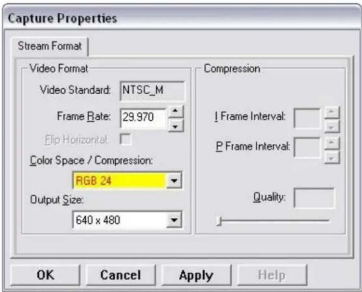
The informaon in this secon applies to DirectShow's standard Pin Properes dialog that many DirectShow applicaons use for seng the video color format, output size, and frame rate for each pin.
This window is the default DirectShow method for obtaining a user's sengs for the output format of captured video.
Changes you make to this window only apply to the currently selected pin. The sengs for the capture and preview pins are independent; in applicaons like GraphEdit, you must set both pins before you use them.
The way to access the Pin Properes window is dierent for each applicaon. In GraphEdit, for example, right click on the pin you wish to set the properes.
Many applicaons do not enable these windows. Instead, they have built-in ways of seng these parameters.
The three acve elds of the dialog set the Color Space or pixel format of captured video; Output Size of the video, and Frame Rate. The recommended order for seng these parameters is:
- Color Space
- Output Size
- Frame Rate
If you set the frame rate before the other two, it may be lost so that you have to reset it.
The Output Size drop-down list displays a selecon of standard size sengs plus one additional seng designated as "default" that DirectShow obtains from the capture driver. You can obtain specialized video sizes by a two-step process:
- Go to the Filter Properes Crop tab described above and set the Default Size to a custom value.
Filters, Pins, and Properes
- Enter the Pin Properes dialog and select the default entry, which will now be set to your custom value.
The area of the dialog marked Compression is not relevant for the Osprey AVStream driver.
The Video Standard seng is read-only in this window. To set the video standard, go to the Input tab, or the Video Decoder tab, of the Iter property pages.
Video standards and sizes
Video standard refers to whether the video signal format is NTSC, PAL, or SECAM. Depending on the exact product version you have, some or all of the following standards are available:
525-line formats:
• NTSC-M – North America
- NTSC-J – Japan
- 625-line formats:
- PAL-B, D, G, H, I – many countries in Europe and elsewhere. B, D, G, H, and I refer to ve nearly identical subformats.
Full-sized NTSC-M and NTSC-J have 525 lines total, 480 lines visible, per frame and a display rate of 59.94 elds per second, or 29.97 interlaced frames per second. Although capture-to-PC applicaons normally use only 480 video lines, the full NTSC frame actually contains 485 video lines, and the AVStream driver provides a control to capture all 485 lines. The control is located on the RefSize property tab.
Full-sized PAL and SECAM have 625 lines total, 576 lines visible, per frame and a display rate of 50 elds per second, or 25 interlaced frames per second.
The standard frame sizes are dierent for NTSC and PAL. For example, the half-frame size in pixels is 360 x 240 for NTSC, and 360 x 288 for PAL. The driver automacally adjusts the reference size and default size for the video standard you are using.
Color formats
The Color format is the arrangement of data bits representing the colors of each pixel. For example, in the RGB555 format, each pixel of data is stored as 5 bits of red, 5 bits of green, and 5 bits of blue color informaon.
Video delivered by the Osprey board to the system is in uncompressed format. It is possible to compress the video at a subsequent stage of processing. However, this dialog eld refers specially to the uncompressed raw video that the board delivers to the system.
The Osprey AVStream driver supports the following capture pin formats.
- YUY2 and UYVY – Each pixel is represented with a total of 2 bytes (16 bits) of data. The data is encoded as separate data for luminance (intensity) and chrominance (color). This mode is mainly used as an input to soware compressors. See YUV format details.
- YUV12 planar – Also known as I420. This is a complex format in which there are in the aggregate 12 bits of data per pixel. Each pixel has 8 bits of luminance data. Each group of 4
adjacent pixels arranged in a 2 x 2 square shares two bytes of chrominance data. See YUV format details.
- YVU9 planar – Similar to YUV12 planar, except that there are in the aggregate 9 bits of data per pixel, and each byte pair of chrominance data is shared by 16 adjacent pixels arranged in a 4x4 square. See YUV format details.
- RGB32 – Each pixel has four bytes (32 bits) of data – one each for red, green, and blue, plus one byte that is unused. The pixel has 256 shades of each of the three colors, for a total of 16.7 million colors.
- RGB24 – Each pixel has three bytes (24 bits) of data – one each for red, green, and blue. This is another “true color” mode with 16.7 million colors.
- RGB555 – Each pixel has two bytes (16 bits) of data. There are 5 bits each of red, green, and blue data; the sixteenth bit is unused. This mode is “high color”, also known as “5:5:5.”
- RGB8 (Greyscale) – The Osprey AVStream driver uses the RGB8 format for greyscale video. RGB8 is a pallezed format. Each pixel is represented by one byte, which indexes one of 256 colors in a color palee specied by the driver. The Osprey driver sets the color palee to greyscale entries, and captures "Y8" luminance-only data.
YUV format details
YUY2, UYVY, YVU9, and YUV12 are YUV formats. In these formats, each pixel is dened by intensity or luminance component, Y, and two color or chrominance components, U and V. Since the human eye is less sensitive to color informaon than to intensity informaon, many video formats save storage space by having one luminance byte per pixel while sharing the chrominance byte among two or more pixels. YUV is also similar to the color encoding used for analog color television broadcast signals.
YUY2 mode, sometimes referred to as 4:2:2 packed mode, consists of a single array of mixed Y, U, and V data. Each pixel has one Y (intensity) byte. Each pixel shares its U and V bytes with one of the pixels horizontally next to it.
YUY2 uses the same number of aggregate bytes per pixel as RGB15, which are two. However, YUY2 is more efficient than RGB15 because it stores relatively more of the intensity information to which that the human eye is most sensitive.
UYVY mode is similar to YUY2 except that the bytes are swapped as follows:
- YVU9 and YVU12 are “planar” modes – the Y, U, and V components are in three separate arrays. It is easiest to explain the format with an example: Let’s say you have a 320 x 240 YVU9 format. The buer has 320 x 240 bytes of Y data, followed by 80 x 60 bytes of V data, followed by 80 x 60 bytes of U data. So each U and each V byte together contain the color informaon for a 4 x 4 block of pixels.
- Similarly, a 320 x 240 YUV12 format has a 320 x 240 Y array, followed by a 160 x 120 U array, and then a 160 x 120 V array.
Note: In the I420 format used by Osprey, the order of the U and V arrays is reversed from the order in the YVU9 format.
Closed caponing (CC)
The Osprey AVStream driver supports NTSC closed capons in three separate ways.
- Through standard DirectShow CC and VBI pin.
- By rendering capons directly onto video on the capture or preview pin. The caponed video can be streamed, written to le, or rendered directly.
• Through an Osprey custom property.
On products other than the Osprey 530/540/560, the driver also provides PAL/SECAM capons as well as teletext data in raw form via the VBI pin (not through the CC pin). Refer to the next secon on Vercal Blanking Interval (VBI) Capture for more informaon. The rest of this secon is specic for NTSC caponing only.
Caponing via CC or VBI pins
The driver supports the standard DirectShow CC and VBI pins on Windows XP; additional les may be required for other Windows operang systems. The CC character pair data can be streamed to applicaons such as Windows Media Encoder 9, or rendered directly to the screen using the DShow Overlay Mixer lter. The 4.6 driver can be set to output CC eld 2 character pairs on the CC pin, instead of the standard CC eld 1 data. XDS (vchip) data is embedded in the eld 2 stream.
The GraphEdit Itergraph shown here displays CC rendered onto preview video. The Overlay Mixer combines the CC overlay with the preview video, which is then rendered onscreen. It is also possible to capture the character pair stream as a standard stream of an AVI le, (although there will be problems with mestamping and synchronizaon); or, to directly manipulate the CC stream in a standard way with a custom applicaon.
Our tesng with the current version of DirectX 9 indicates that closed capons do not render properly with the VMR9 renderer in place of the Overlay Mixer / Video Renderer combination. Therefore, the default Video Renderer in combinaon with Overlay Mixer should be used.
When SimulStream is not installed, the driver supports two CC pin instances. One could be associated with the video capture stream, the other with the preview stream. In pracce, a DirectShow Smart Tee Filter can be inserted into the graph to make any number of VBI pins. When SimulStream is installed, you can have two CC pin instances per SimulStream Iter.
The driver has three built-in user-accessible controls that aect Closed Caponing.
- On the RefSize property page, in the control group shown below, 480-line video must be selected and the radio buon to start video at either Lines 23/286 or Lines 22/285 must be selected.
- On the Capons property page, most of the controls relate to the driver's internal direct rendering on video. The following control selects eld 1 or eld 2 as the eld to be streamed through the CC pin. This control is per-Iter; both available pins on the lter are set the same way. For SimulStream users, the pins on dierent Iters can have dierent sengs.
- On the Device -> Extras... property page, you have the choice to set with Normal or AVI-Compatible mestamping of Closed Capon samples.
This control is a workaround to an apparent problem in DirectShow – if you aempt to capture a CC character pair stream to an AVI le with Normal mestamping, the le becomes extremely large and the capture will fail within a few seconds. The AVI-Compatible mode allows capture of CC to AVI.
Unfortunately, the problem with mestamping means that me synchronizaon between the video and CC streams depend on their physical interleaving in the le, so that me synchronizaon is poor. If the AVI le is set up to be non-interleaved, synchronizaon is not good. If the AVI le is set up to be interleaved, synchronizaon is poor.
For all applicaons other than capture to AVI, this control should be set to Normal. WME9 among others requires the Normal seng if CC is used.
Windows Media Player does not play back an AVI le with an embedded CC stream. The following GraphEdit ltergraph plays back an AVI le containing a video stream plus a CC stream, with the CC rendered on the video:
Direct CC rendering on video
The driver can render closed capons directly onto capture or preview video. The caponed video can be encoded, wrien to le, or rendered directly to the screen.
Filters, Pins, and Properes
CC streaming interface
The driver supports an Osprey custom property which provides the closed capon character stream for use by custom applicaons. The Osprey Iter named CCLineInterp.ax, supplied with the driver package, provides user-mode support for this caponing mode. The Osprey sample applet named CCChannels.exe, also supplied with the driver package, demos a CC line interpreter and XDS (vchip) extracon and display. Both the Iter and the applet are provided in source code form in the SDK.
Vercal Interval Timecode (VITC)
Vercal Interval Timecode (VITC) data is embedded in the Vercal Blanking Intervals (VBIs) of some video content. Timecodes mark each frame with an hour / minute / second / frame number marking that can be used for frame-precise eding.
Figure 95. AcveMovie Window
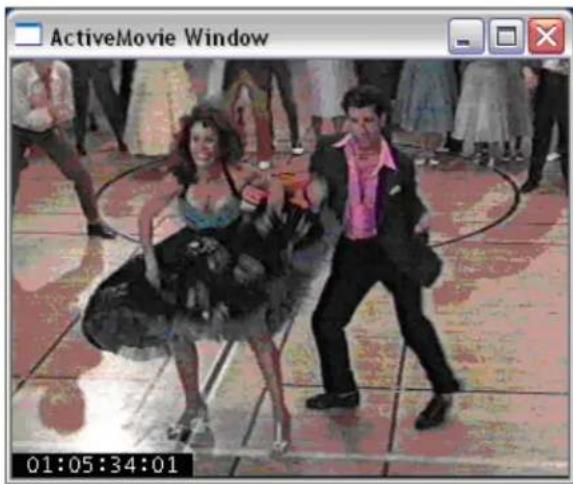
The current Osprey VITC implementaon is preliminary in nature. The features and method of implementaon are subject to change. We invite comments on the mecode-related capabilities that you need for your applicaon.
Osprey's approach to VITC is to invisibly watermark the video bits of each outgoing video frame with its mestamp data. The illustraon shows a mecode extracted from a watermarked frame and rendered as text on the video. Four elements are used to produce it:
• The device extracts mecode data from the vercal blanking interval (VBI) waveform.
- The driver watermarks mecode into the video preview or capture pin's output data.
• A custom Iter decodes the watermark from the video and renders it.
• A GraphEdit graph combines the required Iters.
The Osprey Timecode Filter resides in the module TCOverlay.ax and is installed and registered as part of the standard driver installaon. The source code for this Iter is included in the Osprey AVStream SDK.
The Osprey Timecode Filter also exposes to applicaons a custom property and callback funcon that allows it to return the VITC data for each frame along with the frame's mestamp to the applicaon.
This capability requires custom programming. Refer to the Osprey AVStream SDK Users' Guide. A sample SDK applet named TCApp illustrates the interface.
Figure 96. Timecode Video Marking
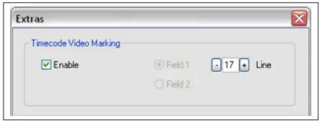
Timecode stamping must be enabled in the driver before it can be used, and the eld and line number correctly set. To access the controls, go to the Device property tab and click Extras...
It is recommended that mecode marking be disabled when not in use, especially the auto search feature – on a slow machine it uses several percent of CPU bandwidth – especially if mecodes are not present.
Note: VITC and LTC – Longitudinal Timecode – are two disnct encoding systems, and this driver supports only VITC.
A suggested reference on mecode is Timecode: a user's guide – 3rd ed., John Ratcli, Focal Press, 1999.
Vercal Blanking Interval (VBI) capture
The Osprey AVStream driver provides DirectShow-compatible VBI pins. VBI data includes Vercal Interval Timecode (VITC) in both the NTSC and PAL worlds. In NTSC, line 21 Closed Caponing (although it is part of the video interval rather than true VBI data), is commonly treated as VBI data. In PAL, World Standard Teletext (WST) is encoded in the VBI data region.
The driver delivers VBI data as raw waveforms, which are then decoded by external DirectShow Iters. DirectShow provides three Iters under the classicaon "WDM Streaming VBI Codecs" that will decode data from VBI pins:
- CC Decoder
• NABTS/FEC VBI Codec - WST Codec
With the Osprey AVStream driver, either the CC pin or the VBI pin can be used to obtain closed capon data. If the VBI pin is used, an extra iter is required to turn the raw waveform into CC character pairs.
When SimulStream is not installed, the driver supports two VBI pin instances. In pracce, a DirectShow Smart Tee Filter can be inserted into the graph to make any number of VBI pins. When SimulStream is installed, mulple VBI pins are allowed.
Setting audio driver properties
Setup and control for audio are much simpler than for video.
Setting the audio source and input volume
The audio source is set using the Osprey mixer driver interface. Most applicaons, including the Windows Media Encoder applicaons, interface to the mixer driver directly and expose the look and feel specific to that applicaon. However, the default Windows interface to the mixer driver can also be used.
To set the audio source and input volume:
- Right click the speaker symbol on your taskbar (typically on the boom right-hand side of your screen).
- Click Playback devices (Figure 97).
Figure 97. Open Playback devices
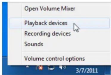
The Sound window displays with a list of recording devices (Figure 98).
Figure 98. Sound window
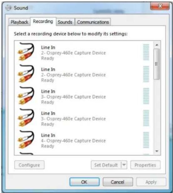
Windows XP species
To get to the Osprey audio capture (recording) device, select Properes under Recording Control opons menu. This opens the Properes window. Click on the Mixer device drop-down list at the top to see the list of audio input and output devices, including one or more Osprey cards. When you have chosen the device, click OK, and you will be returned to the Recording Control display (Figure 98).
The Osprey device is not a mixer in that it does not allow for mixing the various audio sources.
Therefore, when one audio input is selected, any other input previously selected becomes unselected.
The Select check box at the boom of each source sets which source is being used.
Osprey cards have hardware gain control. To control hardware gain, use the volume slider in the mixer applet. The unity gain seng is when the volume slider is all the way up (in default driver sengs).
The quick-access volume control (le click on the speaker symbol) on the task bar controls recording volume and playback volume. To change record levels, go to Opons > Properties > Recording.
Audio properties window
OspreyCong's audio properes window enables you to access:
- Standard volume controls – input select, volume, mute, and peak meter for Osprey audio Iters (also referred to as the Recording Controls)
- Custom audio controls
It also has a sound check listening or monitoring funcon.
OspreyCong runs from an icon in the Nocaon Area at the far right of the system Start Bar. To display OspreyCong, right-click on the icon and select a device from the menu. The OspreyCong audio properes window displays in basic mode (Figure 99).
Basic mode
Figure 99. Audio properes window – Basic mode
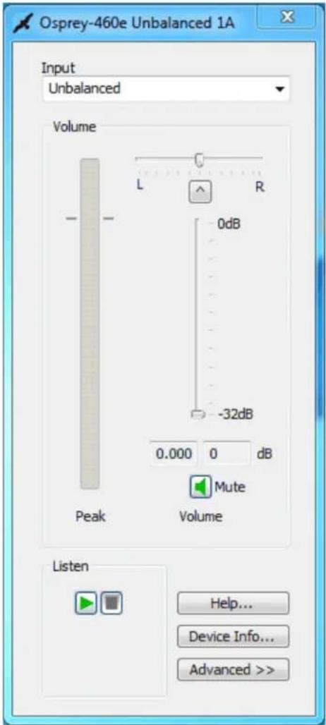
The basic mode has the following controls:
| Input | Select which input line is acve. |
| Volume | The mixer control group includes several controls:The volume slider controls both stereo channels at once.The balance control aenuates the le or right channel. The le channel is aenuated when the slider is moved right of center, otherwise is unaenuated; the right channel is aenuated when the slider is moved le of center, otherwise is unaenuated. At the center posion both channels are unaenuated.The balance control buon centers the control.Mute always mutes both stereo channels.The peak meter shows the current audio level on both channels. The level shown is the nal output from the driver condioned by the Volume and Balance sliders in the mixer group as well as the Preamp sliders in the Advanced group. The peak meter works only when the device is acvely capturing audio, either using OspreyCong's built-in monitor, or under the control of another applicaon. |
| Listen | The listen funcon provides a basic sound check through the system default sound renderer. You can instead monitor sound through your main applicaon at the same me you are making adjustments in OspreyCong. Click the green triangle to play and the red square to stop. |
| Help | Click to access the user help les. |
| Device Info | Click to access informaon about the hardware device and its driver. |
| Advanced/Basic | Click Advanced to open a second pane showing advanced mode custom audio controls (see Advanced mode).Click Basic to collapse the second pane back to basic mode. |
| Preamp | Adjust the analog prescale and soware boost. Click Default to return the sengs to the default levels. |
| Mono Source Mode | Choose the source mode:Use Le ChannelUse Right ChannelUse Le + Right Average |
| Dual Mono | Click this buon to access the Dual Mono window (see Dual Mono). |
| Test Signals | Access the Test Signals window to set the test signal mode and test signal frequency (see Test Signals). |
Vista or later species
OspreyCong running under Windows 7 generally follows the Windows 7 Core Audio Point to Point model. Each Osprey input is a separate audio Point or Filter.
For example, an Osprey 530 has ve audio inputs – unbalanced, balanced, AES/EBU, SDI 12 and SDI 34 - which appear in Vista or later device lists as ve separate source Points or Filters. When you select one of these Iters, you not only select the Osprey 530, but you also implicitly switch the boards internal input selector to the input associated to the Iter you have chosen. To put it another way, the two steps under XP – (1) select the board; (2) select the input – are condensed into one – select the Iter for the desired board and input.
The Vista or later version of the OspreyCong Basic property page looks similar to the XP version with some important functional differences. Most of the difference is in how the Input selecon box at the top of the panel works.
- XP – When you select an input, the Osprey board's internal selector immediately switches the board to that input. If another applicaon is using this board as its audio source, the applicaon's selecon is overridden without warning.
- Vista or later – When an applicaon is running with a parcular input selected, the applicaon owns the device and that input selecon. Neither OspreyCong nor any other applicaon except the owner can change the input selecon. Only the owning applicaon can do that, by releasing its current Filter selecon, and selecng a new Filter for the desired input.
When OspreyCong selects a line on a device that is currently in use by another applicaon, the Input control shows the name of that line followed by the designaon Acve. OspreyCong's Listen funcon can monitor that audio on the currently acve line.
If no applicaon is currently streaming audio through the device, no line is marked as Acve. If
OspreyCong starts to monitor a line via the Listen buon, that line becomes marked Acve.
OspreyCong in this case becomes the owning applicaon, and no other applicaon is able to change the input selecon until OspreyCong stops listening.
OspreyCong's peak meter only works when the Acve line is selected and sound is on the line.
When OspreyCong selects the Acve line, the volume, balance, and mute controls operate on the acve audio stream, including the audio going to the applicaon that owns the input.
The Mute buon always aects the Acve line. The driver does not store this seng separately for each audio line.
Advanced mode
Click Advanced to open up the advanced custom Cong controls.
Vista or later Note: The controls on this page work the same on XP and Vista, except Preferred Audio Sample Rate is not on Vista. The windows in this user guide are on a Windows 7 64-bit operang system.
Figure 100. Audio properes window – Advanced mode
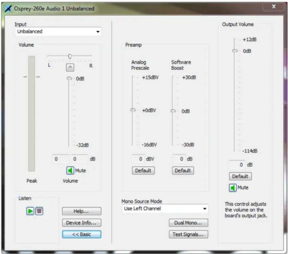
Note: This window is for the Osprey 260e video card. The Mute buon on the Input secon does not display on the Osprey 210e. Also, the Output Volume secon on the far right of the window only displays on the Osprey 260e.
The Advanced mode has the following controls:
| Preferred Audio Sample Rate (XP only) | This control is not provided, or needed for Vista or later.The system sound control has a default rate control that has about the same eect. The system control is in Sounds (the speaker icon in the nocaon area or in the Control Panel). Right click on the nocaon area Sounds icon and select Recording Devices. Or, click Sounds in the Control Panel and select the Recording tab. Highlight a capture Iter and click Properes. Go to the Advanced tab and select the Default form desired. |
| Preamp | The Preamp controls set the hardware Analog Prescale level and a Soware Boost factor. |
| Mono Source Mode | This control tells the driver what to do when the audio capture client connects to the driver via a monaural channel. It has no eect in the usual case the conneccon is via stereo channels. |
| Dual Mono | The Dual Mono window enables a special mode of the driver in which the le and right stereo pair inputs to a device are used as two separate mono channels serving two separate audio capture lters. |
| Test Signals | The driver emits a test signal in place of the normal incoming audio. |
Preferred audio sample rate (XP only)
At the top of the advanced mode panel (for XP only) is a control for Preferred Audio Sample Rate. Osprey hardware can deliver audio at a hardware sample rate of 32.0 kHz, 44.1 kHz, or 48.0 kHz. With this control you can force just one of these rates. The control tells the driver to tell applicaons that it only supports the selected rate rather than all three rates.
Most oen you want to let the audio applicaon control which sampling rate will be used; however, there are cases where you may want to force a parcular rate. If you use soware sample rate conversion, the system does not necessarily select the opmum hardware rate for a given soware rate. For example it may specify a 44.1 kHz hardware rate when supplying 16 kHz soware rate to the applicaon. In this case, it would be beer to set the Preferred Audio Sample Rate 32 kHz, so that downsampling is exactly 2:1.
This control takes eect when the device's audio streams are restarted – you may have to restart the applicaon to pick up the change.
In general, Osprey hardware can deliver audio at a hardware sampling rate of 32.0 kHz, 44.1 kHz, or 48.0 kHz, with the following excepons:
- The Osprey 200 always delivers audio at 44.1 kHz. (This card is older and no longer sold. The new Osprey 210, 230, 300, and 440 do not have this restricon.)
- The Osprey 5xx series (Osprey 530, 540, and 560) have an SDI input that only supports 48.0 kHz audio sampling. The driver overrides any other Preferred Audio Sample Rate.
- The Osprey 540 and Osprey 560 have a DV1394 input. When the audio input is DV1394, you may have to use the Preferred Audio Sample Rate control to match your audio sample rate to the actual rate of the incoming data. The usual formats are 48 kHz/16-bit, and 32 kHz/12-bit, You may have to listen to a captured sample of your audio to determine whether the sample rate is set correctly – if the pitch is incorrect or there are disconnuies, try the other seng.
Preamp
The Preamp controls set the hardware Analog Prescale level and a Soware Boost factor. The sengs are separate for each input of each device, and are applied to whichever input is selected in the current applicaon or in the system mixer.
It is recommended that you use the system Volume control in the Basic pane of the dialog (or in the system mixer) for general purpose volume seng. Use the preamp controls to opmize and normalize signals:
- The Analog Prescale seng is meaningful only for the analog unbalanced and balanced inputs, and is calibrated dierently for each. When a digital input is selected this control is disabled. The Osprey 200 does not have this seng.
Analog Prescale is an analog hardware gain control with the default level chosen such that the expected amplitude of a full volume input signal will have adequate headroom without clipping. If you do experience clipping, or are working with low-level signals, you can adjust this level. On this control, a higher reference level results in lower gain, so the quietest seng is at the top of the scale. Click Default to restore the default value.
- The Soware Boost seng is a soware gain adjustment that applies to both analog and digital inputs. Boost can be set individually for each input. It supplements the system volume control by providing a wide adjustment range. You can use it to calibrate or normalize input levels across mulple inputs; or to accommodate microphones or other non-line inputs that have nonstandard signal levels. Click Default to restore the default levels.
Mono source mode
This control tells the driver what to do when the audio capture client connects to the driver via a monaural channel. It has no effect in the usual case the connecion is via stereo channels.
The control signals the driver whether the audio for the mono conncon should come from the le physical channel, the right physical channel, or an average of both.
- If Mono Source Mode is set to Use Le Channel, the audio from the le physical channel is copied to the mono desnaon buer.
- If Mono Source Mode is set to Use Right Channel, then audio from the right physical channel is copied to the mono desnaon buer.
- If Mono Source Mode is set to Average Left and Right, audio from the le and right physical channels is averaged, and the result is put in the mono desnaon buer.
When Dual Mono mode is in eect, the Mono Source Mode control has no funcon and is disabled. In Dual Mono mode there is only one physical source channel, and therefore you do not need to choose which channel to use.
Dual Mono
The Dual Mono window enables a special mode of the driver in which the le and right stereo pair inputs to a device are used as two separate mono channels serving two separate audio capture Iters. A typical use for this mode is audio-only applicaons where stereo is not needed and maximum density of inputs per system is the driving factor.
In Dual Mono mode, each audio device enumerates as two separate Iters, respectively for the le and right physical inputs. The Iters' names will have L and R suxes, for example, Osprey 230 Audio Device 1L.
These Iters behave for the most part like normal audio Iters. When you use AudioCong, or most other applicaons, you connect with either the L or R Iter, one at a me, not both. The user volume, balance, and mute (Basic mode of AudioCong) are independent for the L and R Iters. Each has two quasi-stereo outputs. The audio is identical on each quasi-channel, except that the user balance control can be used to reduce the volume on one channel.
However, the underlying hardware requires:
- Both Iters of the pair must be set to the same audio input – unbalanced, XLR balanced, etc.
- Both must have the same hardware prescale and soware boost sengs.
• The Mono Source Mode control has no meaning in Dual Mono mode, and is disabled.
This control globally aects all audio devices of the category that the dialog is accessing (that is, all Osprey 2X0s as a group, or all Osprey 5X0s as a group). When the seng is changed, you have to restart the system for the change to take eect.
Figure 101. Dual Mono
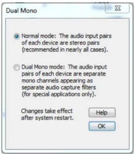
Test Signals
Using the Test Signals window (Figure 102), you can have the driver emit a test signal in place of the normal incoming audio. The raw test signal is a sine wave with full 16-bit amplitude (range -32767 to +32767).
The test signal can be injected at either of two points in the driver's processing. In both cases, the signal is a soware-generated waveform that is injected downstream of the hardware.
- The rst opon is to inject the signal into the earliest possible point in audio processing. That means it is placed in the driver's Direct Memory Access (DMA) buer, overwring the normal capture data. This form of the test signal will be modified by all user controls except the analog input hardware prescaler. Volume, mute, and balance controls will all act the signal. If A/V Acve Sync is used, or if rate conversion occurs, these operaons will be performed on the test wave. The peak meter reading will show all modicaons of the signal level. The signal will be converted to 8-bit format or to mono if either is specied. If the device is sourcing mulple audio streams, the test signal will appear on all these streams.
- The second opon is to inject the signal at the last possible point in the driver's audio processing. The raw sine wave is copied into the outgoing client buer in place of the normal received waveform. This signal is not modified by the driver's volume, balance, or mute controls. The peak meter will show the level of the incoming signal, not of the test wave. The output format must be 16-bit stereo, of the test signal will not be injected.
There is also the choice to emit an exact 1 kHz waveform, or a 997 Hz waveform. The 997 Hz opon may be useful for some kinds of troublesomeong since the periodicity of the waveform will not coincide with buer packet boundaries.
In all cases, the sample rate of the test wave will be the same as the rate of the incoming audio. For analog inputs, the on-board sample clock determines the rate. For Osprey 5X0 digital inputs (AES-EBU), SDI, or DV1394) the clock embedded in the incoming signal is used.
This control aects the one speci Osprey audio device currently being accessed; to switch all devices to a test signal you would have to repeat the operaon for each individually.
As soon as you click the buon, this control is eecve immediately.
Figure 102. Test Signals
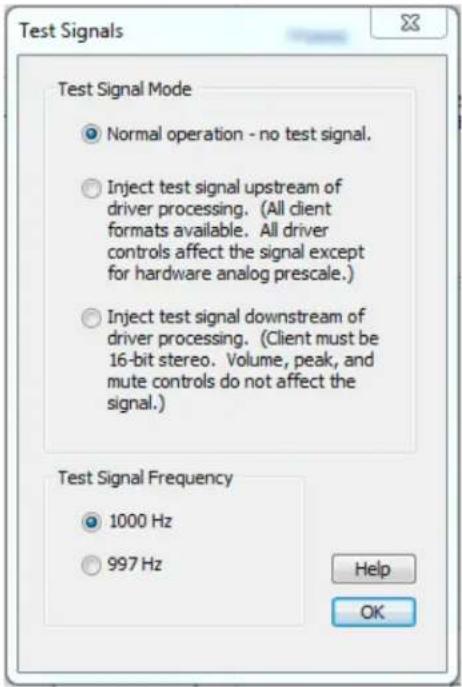
Appendix A: Osprey hardware specifications
Osprey 100e
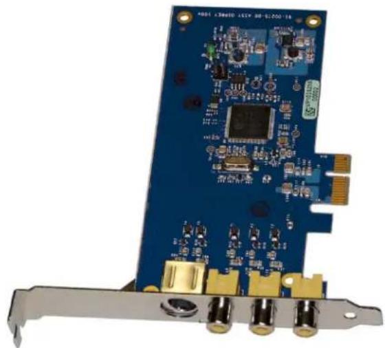
natural_image
Close-up of a blue PCI card with gold connectors and various electronic components (no visible text or symbols)Environmental specicaons
| Operang temperature range | 0° to 40°C |
| Non-operang temperature range | -40° to +75°C |
| Operang humidity range | Between 5 % and 80 % (non-condensing) @ 40°C |
| Non-operang humidity range | 95 % RH (non-condensing; gradient 30 % per hour |
| Operang altitude range | 0 to 3,048 meters (10,000 feet) |
| Non-operang altitude range | 0 to 15,240 meters (50,000 feet) |
• PCI Express Bus compliant
• Approximate card weight = 42 grams
Figure 103. Osprey 100e backplate
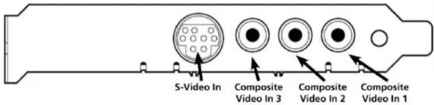
Osprey 210e
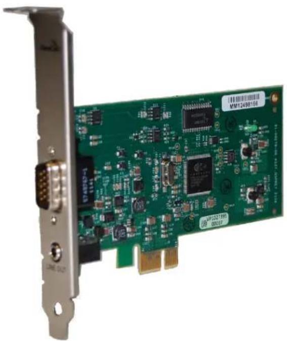
natural_image
Green PCI card with various electronic components and connectors, mounted on a metal frame (no readable text or symbols)Environmental specicaons
| Operang temperature range | 0° to 40°C |
| Non-operang temperature range | -40° to +75°C |
| Operang humidity range | Between 5% and 80% (non-condensing) @ 40°C |
| Non-operang humidity range | 95% RH (non-condensing; gradient 30% per hour |
| Operang altitude range | 0 to 3,048 meters (10,000 feet) |
| Non-operang altitude range | 0 to 15,240 meters (50,000 feet) |
• PCI Express Bus compliant
• Approximate card weight = 42 grams
Figure 104. Osprey 210e backplate

Osprey 260e
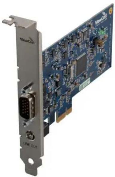
natural_image
Close-up of a blue PCI card with visible circuitry and connectors, no text or symbols present.Environmental specicaons
| Operang temperature range | 0° to 40°C |
| Non-operang temperature range | -40° to +75°C |
| Operang humidity range | Between 5% and 80% (non-condensing) @ 40°C |
| Non-operang humidity range | 95% RH (non-condensing; gradient 30% per hour |
| Operang altitude range | 0 to 3,048 meters (10,000 feet) |
| Non-operang altitude range | 0 to 15,240 meters (50,000 feet) |
• PCI Express Bus compliant
• Approximate card weight = 65 grams
Figure 105. Osprey 260e backplate
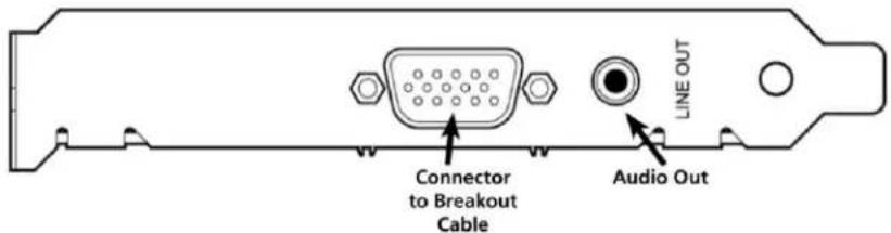
Osprey 460e
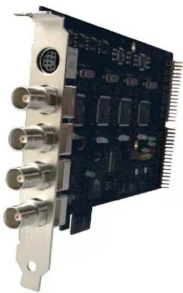
natural_image
Close-up of a black electronic circuit board with multiple connectors and ports (no visible text or symbols)Environmental specicaons
Operang temperature range 0^ to 40^ C
Non-operang temperature range -40^ to +75^ C
Operang humidity range Between 5 % a
Non-operang humidity range 95 % RH (non-condensing; gradient 30 % per hour
Operang altitude range 0 to 3,048 meters (10,000 feet)
Non-operang altitude range 0 to 15,240 meters (50,000 feet)
• PCI Express Bus compliant
• Approximate card weight = 227 grams
Figure 106. Osprey 460e backplate
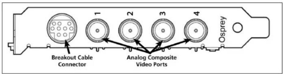
Appendix B: Osprey Breakout Cables
Osprey 210e breakout cable
Figure 107 shows the Osprey 210e connector on the bracket.
Figure 107. 15 pin mini-DIN male on Osprey bracket
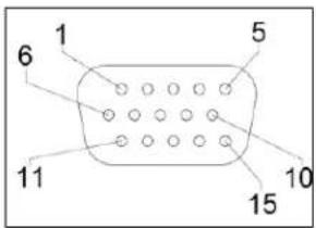
| Pin | Funcon |
| 1 | Unbalanced le audio in, Tip for 3.5mm audio |
| 2 | Unbalanced right audio in, Ring for 3.5mm audio |
| 3 | Ground for 3.5mm audio |
| 4 | |
| 5 | |
| 6 | S-Video Luma (to mini-DIN 3) |
| 7 | Ground for R & L unbalanced audio |
| 8 | |
| 9 | Composite video ground |
| 10 | S-Video Luma and Chroma ground (to mini-DIN 1 & 2) |
| 11 | |
| 12 | |
| 13 | |
| 14 | S-Video Chroma (to mini-DIN 4) |
| 15 | Composite video |
Osprey 260e breakout cable
Figure 108 shows the Osprey 260e connector on the bracket.
Figure 108. 15 pin mini-DIN male on Osprey bracket
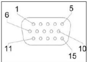
| Pin | Funcon |
| 1 | Unbalanced le audio in |
| 2 | Unbalanced right audio in |
| 3 | Shield for R & L balanced audio (to XLR pin 1) |
| 4 | Balanced Audio Le + (to XLR pin 2) |
| 5 | Balanced Audio Right - (to XLR pin 3) |
| 6 | Y / S-Video Luma |
| 7 | Ground for right unbalanced audio |
| 8 | Ground for le unbalanced audio |
| 9 | Pb / Composite video ground |
| 10 | S-Video Luma Ground |
| 11 | Balanced Audio Le - (to XLR pin 3) |
| 12 | Pr / S-Video Chroma ground |
| 13 | Balanced Audio Right + (to XLR pin 2) |
| 14 | Pr / S-Video Chroma |
| 15 | Pb / Composite Video |
Osprey 460e breakout cable
Figure 109 shows the Osprey 460e connector on the bracket.
Figure 109. 9 pin mini-DIN on Osprey bracket
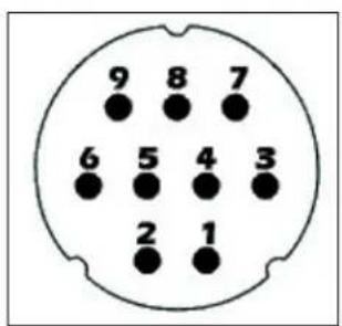
| Mini-DIN | Signal | RCA Connectors |
| 1 | Channel A Le | Channel A Le Center |
| 2 | Channel A Right | Channel A Right Center |
| 3 | Channel B Le | Channel B Le Center |
| 4 | Channel B Right | Channel B Right Center |
| 5 | Channel C Le | Channel C Le Center |
| 6 | Channel C Right | Channel C Right Center |
| 7 | Channel D Le | Channel D Le Center |
| 8 | Channel D Right | Channel D Right Center |
| 9 | Shield | Channel A Le Shield |
| 9 | Shield | Channel A Right Shield |
| 9 | Shield | Channel B Le Shield |
| 9 | Shield | Channel B Right Shield |
| 9 | Shield | Channel C Le Shield |
| 9 | Shield | Channel C Right Shield |
| 9 | Shield | Channel D Le Shield |
| 9 | Shield | Channel D Right Shield |
Appendix C: Troubleshooting
Color bars on video screen
The Osprey 460e AVStream driver has a built-in color bar generator. If color bars appear in your video preview window, it is an indicaon that video is not present on the selected video input (Figure 110).
The color bar display can be adjusted or changed in the Device Properes tab, including the text overlay on the screen.
Figure 110. No-Video Test Paern
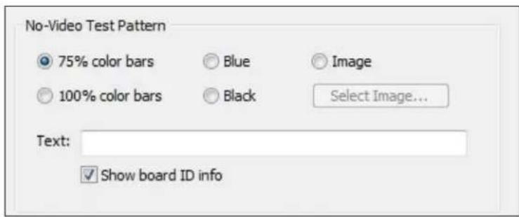
To solve this problem, check the following:
- Check that the camera, VCR, or other video source is powered and that its output is connected to the Osprey card's input.
- Check that the correct video input is selected in the Control Dialog's Source page.
Scrambled video image
You may have set the wrong video signal format for the signal input you are using. For example, you may have told the driver to look for NTSC-M video but are using a PAL-BDGHI video source. Make sure you know what signal format your video source is generang. Go into the Video Standard eld of the Control Dialog's Source page, and click the buon for that signal format.
Poor video quality at large frame sizes
Large frame sizes with the deep pixel depth (24- or 32-bit), or complex format (YVU9 or YUV12 planar), impose heavy demands on the PCI bus' data transfer capacity. Our experience is that some systems cannot handle these formats at full frame sizes.
Systems vary in their data transfer limits. The characteriscs of the PCI bridge are oen more important than processor speed.
If you are having problems, we recommend that you:
- Use a smaller frame size (480 x 320 or less).
- Use a shallower color format (RGB15 or RGB24 instead of RGB32).
- Try a YUV format instead of an RGB format, and a packed format instead of a planar format.
If you have a choice of PCs for video capture, try using another system with a dierent system board chipset.
Multiple horizontal lines across video image
If there are mulple, regularly spaced, horizontal lines across your video image and your source material is copyrighted and copy-protected, you are seeing Macrovision™ copy protecon.
The lines can vary in color from yellow to blue to green. These lines are not present in every frame of video. There may also be a black band at the top of the frame.
There are other brands of copy-protecon besides Macrovision. Some of these employ similar methods (resulting in the above) and others do not. This is a good example of Macrovision eects but you should find a good way if possible to briefy note that there are other forms of copy protecon and that they may have different eects on the picture.
Cannot play back recorded audio
If you have a sound card installed, you should be able to hear audio when you play back recorded audio.
Verify that the volume control for your playback device is not muted.
Verify that the selected playback device is your sound card. Some Windows applicaons cannot use a recording device unless a playback device is also installed. The Placeholder device cannot play back recorded audio. You can use the same method to select playback device that you use when selecng the audio source.
Audio recording control comes up with wrong device and wrong inputs
The cause of this problem may be that you currently have or have had previously, a Video for Windows audio capture driver installed in the system. The Osprey AVStream install process normally removes a previous Video for Windows driver, but if you have mulple Osprey cards installed you do have the opon of running the Video for Windows driver on some cards and the AVStream driver on others. Unfortunately the Recording Control does not work smoothly in this situation. The Video for Windows device will always try to act like it is the selected device even if it is not. You have to manually enter Recording Control's Opons ➤ Properes dialog to select your device.
If you no longer have a need for the Video for Windows driver, you can uninstall it using instrucons obtainable from Osprey technical support. If you are comfortable using RegEdit to edit your registry, you can instead go to the following locaon:
HKEY_LOCAL_MACHINE\SOFTWARE\Microsoft\Windows NT\CurrentVersion\Drivers32
Index
+, 20
16:9 Wide, 40
1X Scale, 83
2-frame algorithm (less CPU), 53
3D comb Itering, 61
3D Itering, 61
3-frame algorithm, 52
525-line, 43
525-Line (NTSC) Vercal Format, 39, 43
525-line standard, 39
625-line, 43
625-line standard, 39
A
A/V Timing, 57
Accessing the OspreyCong Ulity, 19
AcveMovie Window, 104
Adapter, 28
Adapve Deinterlace window, 52
Adding or moving boards, 16
Adjust buon, 52
Apply, 24
Audio and video mestamps show, 68
Audio properes window – Advanced mode, 112
Audio properes window – Basic mode, 109
Audio/Video Timing, 66
Auto, 48
Auto mode, 49
Auto Size check box, 89
Auto Sizes, 89
B
Backlight Comp, 34
basic reference size, 94
Board Numbering, 57, 70
Both, 25
Both buon, 25, 75, 80, 85
Brightness, 33
Brightness and Contrast, 34
Browse for File buon, 80
buers, 58
Buers Requested, 56, 58
C
Cancel, 24
Capons tab, 24, 74
Capture, 25
Capture buon, 25, 75, 80, 85
Capture color format, 86
Capture pin, 59
capture pin formats, 100
Capture Properes, 99
CC Channel, 76
CC Pin, 74, 77
CCIR-601, 39
Change
default sengs of the driver, 23
Cine Phase, 51
Close, 21
Closed Capon Timestamps, 72
closed caponing, 103
Color Enable, 34
Color formats, 100
Composite/SVideo dongle, 28
Contrast, 33
C (cont.)
contrast rao, 34
Creang dierent sengs for the capture and preview pins, 75
Crop tab, 38
cropping, 84
Current Using sengs, 51
Currently Using, 45
Currently Using group, 51
custom properes, 48
D
Debug tab, 23, 37
Default Output Size, 84, 85, 89
Default Output Size group, 88
degree of weighng, 82
deinterlace, 23, 45, 48, 49, 91, 94, 97
Deinterlace sengs, 48
deinterlacing, 45
Desnaon Folder window, 11
detelecine, 23
Device controls, 56
Device Info, 56, 65
Device Info window, 65
Device tab, 24, 56
Diagnosc Logging, 56, 62, 63
DirectShow, 19, 91
Disabling 3D comb Itering, 60
Dual Mono, 113, 115
E
EaseStream, 61
Enable Cropping, 85
Enable Cropping, 87
Enable Cropping check box, 89
Enable Key Color, 81
Enable Key Color check box, 81
Enable Key Color on File and Color sub tab, 78
Enable Logo check box, 80
Enable Logo on File and Color sub tab, 78
End-User License Agreement, 10
External deinterlacers, 49
Extras, 57, 72
F
Field 1, 77
Field 2, 77
File and Color, 80
Itergraph, 96
Filters tab, 23, 45
Iters, pins, and properes, 91
Flash/Click A/V Sync Test, 69
G
Gain, 34
Gamma, 33, 34
gamma correcon, 94
Global controls, 25
Granularity, 85
Granularity controls, 86
granularity restricons, 86
H
Help, 21
Horizontal Delay, 39, 41
Horizontal Format, 39
Hue, 33, 34
|
Inial OspreyCong user interface, 20
Input tab, 23, 26
Install Completed, 13
Installing the driver, 9
Installing the hardware, 15
I (cont.)
Installing the video capture card, 14
inverse telecine, 48, 49, 53, 94
inverse telecine deinterlacing, 48
inverse telecine process, 50
K
key color, 81
L
Limited Warranty, 6
Lines detected, 36
Logo posion, 82
logo property controls, 78
Logo tab, 24, 78, 83
M
Mono Source Mode, 112
moon adapve, 48, 53
moon adapve deinterlace, 50
moon adapve deinterlacing, 48, 49, 94
moon threshold, 52
mulple Iters, 47
N
No-Video Test Paern, 56, 57, 129
NTSC, 49
NTSC Closed Capon, 47
Nudge buons, 82, 83
Number of Capture Buers Requested, 58
0
OK, 24
one Iter, 47
Osprey 260e Lemost posion, 61
Osprey 260e PCIe Bus Usage, 59
Osprey 260e Rightmost posion, 62
Osprey 260e Third posion, 61
Osprey 460e backplate, 126
Osprey 460e Lemost posion, 61
Osprey 460e PCIe Bus Usage, 59
Osprey 460e Rightmost posion, 62
Osprey 460e Third posion, 61
Osprey soware CD, 9
Osprey Video Device Properes window tabs, 23
Other check box, 81
Output Enable, 36
Overlay Mixer, 102
P
PAL/SECAM, 49
PCIe Bus Usage, 56
Pin Properes, 38
Pin Select, 25, 74, 75, 78, 80, 85, 86
Pin Select buons, 25
Pin Select seng, 86
Place OspreyCong icon in the Control Panel, 20
Place OspreyCong icon in the Taskbar, 21
Playback devices, 107
Posion and Size sub tab, 79
Post-Processing mode, 93
PowerLine Frequency (An Flicker), 34
Preamp, 112
Preferred Audio Sample Rate (XP only), 112
Preview, 25
preview and capture pins, 86
Preview buon, 25, 75, 80, 85
Preview color format, 86
Preview pin, 59
Q
Quick Start, 66
R
Ready to install, 12
Recalc buon, 87
Reference Size, 85
Reference Size for Crop and Logo Placement, 39, 43
RefSize, 38
RefSize tab, 38
RefSize tab, 23
Remove Previous Installaon, 9
Render, 74, 75
Render Logical White as, 74
Render Logical White As, 76
Reseller Pass Through of Standard Limited Warranes, 6
Restart window, 13
Selecng a device for conguraon, 22
Selecon control numbering, 27
set cropping area, 84
Seng the audio source and input volume, 107
Sharpness, 33, 34
Show [4] Iters per device, 47
Show board ID info, 58
Show board ID info eld, 71
Show Properes for Selected Filter, 20
Signal Detected, 36
SimulStream, 7, 23, 42, 45, 46, 91, 92, 93, 94, 102, 103, 105
SimulStream enabled, 46
Size and Crop tab, 24, 84
Sound window, 108
Source Width, 39, 41, 42
Square Pixels, 39
System Sengs Change Window, 15
T
telecine, 48, 50
Test Mode, 53
Test paerns, 71
Test Signals, 113, 117
Timecode Video Marking, 72, 105
Timestamp audio and video width, 67
Tolerance, 81
Tolerance control, 81
Trimming an image, 42
Typical PCI Express Slot diagram, 14
U
Use WideScreen Signal (WSS), 40
Ulies, 26
V
VbiGraph ulity, 32
VCR Input, 36
vericaon of video data, 60
vercal blanking interval, 40
vercal blanking intervals, 104
Vercal Interval Timecode, 104
Vercal scaling, 49
Video Decoder, 35
Video Decoder tab, 23, 35
video Iter, 22
Video Input, 26, 27, 28
Video Input group, 27
Video Mixing Renderer 7, 96
Video Mixing Renderer 9, 97
Video Present, 26
Video Proc Amp controls, 94
Video Proc Amp tab, 23
Video Renderer, 95
video rendering, 95
Video Standard, 26, 29, 36, 100, 129
Video Standard drop-down list, 29
Osprey Analog PCIe Series User Guide
V (cont.)
Video Standard eld, 29
Video Standard window, 11
VideoCheck ulity, 30
VideoProc Amp, 33
VideoProc Amp tab, 33
VMR7, 96, 97
VMR9, 97
W
Warranes, 6
Weighng, 82
Weighng on File and Color sub tab, 78
Welcome to the Setup Wizard, 10
When to deinterlace, 49
White Balance, 34
Windows Security window, 12, 15
Y
YPrPb (Component), 27
Osprey®
by VARIOSYSTEMS
ospreyvideo.com


- UL Statement
- Contents
- Overview....1
- Installation Steps 5
- Setting Video Driver Properties....15
- Filters tab 40
- Device tab 51
- Capons tab 68
- Logo tab 73
- Size and Crop tab 79
- Filters, Pins, and Properties 85
- Post-Processing mode....87
- Ecient Video Rendering 89
- Setting audio driver properties ....101
- Appendix A: Osprey hardware specifications....113
- Appendix B: Osprey Breakout Cables....121
- Appendix C: Troubleshooting ....125
- Overview
- Product Description
- Audience
- Conventions for this guide
- Warranties
- Limited Warranty
- Reseller Pass Through of Standard Limited Warranes
- System requirements
- Minimum system requirements
- Installation Steps
- Installing the driver
- To install the driver:
- Installing the video capture card
- To install the video capture card:
- Installing the hardware
- To install the hardware:
- Multiple board types
- Adding or moving boards
- To add or move boards:
- Setting Video Driver Properties
- OspreyConfig's initial processing sequence
- Understanding the device properties window
- Common buons
- Per-device, per-pin, and global controls
- Input tab
- Video Input group
- Osprey 260e
- Osprey 460e
- Video standard group
- Ulies
- VideoCheck ulity
- VideoGraph ility
- VbiGraph ulity
- Video Proc Amp tab
- Video Decoder tab
- RefSize tab
- Horizontal Format
- Horizontal Delay
- Source Width
- To trim an image:
- Reference Size for Crop and Logo Placement
- 525-Line (NTSC) Vercal Format
- Filters tab
- SimulStream
- One Iter
- Figure 40. One Iter
- Mulple Iters
- Figure 41. Mulple Iters
- Deinterlace
- When to deinterlace
- Background – telecine and inverse telecine
- Background – moon adapve deinterlace
- Currently Using group
- Adapve Deinterlace window
- Notes:
- Eects on video latency
- Device tab
- No-Video Test Paern
- Buers Requested
- PCIe Bus Usage
- Disabling 3D comb Itering
- Vericaon of video data
- EaseStream
- Sengs details
- Diagnosc logging
- Device Info
- A/V Timing
- Quick Start
- Timestamp audio and video width
- Presentaon Time Adjustment
- Flash/Click A/V Sync Test
- Board numbering
- Extras
- Captions tab
- Pin Select
- To create dierent sengs for the capture and preview pins:
- Render
- CC Channel
- Render Logical White As
- Closed Capon DirectShow Pin
- Logo tab
- File and Color
- Enable Key Color
- Weighng
- Posion and Size
- Size and Crop tab
- Reference Size
- Granularity
- Enable Cropping
- Recalc buon
- Default Output Size
- Filters, Pins, and Properties
- Post-Processing mode
- Efficient Video Rendering
- Preview Pin to Video Renderer
- Preview Pin to VMR7
- Preview Pin to VMR9
- Some Data Points
- Capture Properes
- Video standards and sizes
- Color formats
- YUV format details
- Closed caponing (CC)
- Caponing via CC or VBI pins
- Direct CC rendering on video
- CC streaming interface
- Vercal Interval Timecode (VITC)
- Vercal Blanking Interval (VBI) capture
- Setting audio driver properties
- Setting the audio source and input volume
- To set the audio source and input volume:
- Windows XP species
- Audio properties window
- Basic mode
- Vista or later species
- Advanced mode
- Preferred audio sample rate (XP only)
- Preamp
- Mono source mode
- Dual Mono
- Test Signals
- Appendix A: Osprey hardware specifications
- Osprey 100e
- Environmental specicaons
- Osprey 210e
- Appendix B: Osprey Breakout Cables
- Osprey 210e breakout cable
- Osprey 260e breakout cable
- Osprey 460e breakout cable
- Appendix C: Troubleshooting
- Color bars on video screen
- Scrambled video image
- Poor video quality at large frame sizes
- Multiple horizontal lines across video image
- Cannot play back recorded audio
- Audio recording control comes up with wrong device and wrong inputs
- Index
- A
- B
- C
- C (cont.)
- D
- E
- F
- G
- H
- |
- I (cont.)
- K
- L
- M
- N
- 0
- P
- Q
- R
- T
- U
- V
- V (cont.)
- W
- Y
- Osprey®
Brand : Osprey
Model : 210e
Category : Soundcard