
DH-TPC-DF1241N-D - Camera Dahua Technology - Free user manual and instructions
Find the device manual for free DH-TPC-DF1241N-D Dahua Technology in PDF.


| Product Type | Thermal Network Camera |
| Brand | Dahua Technology |
| Model | DH-TPC-DF1241N-D |
| Sensor | Uncooled vanadium oxide (VOx) microbolometer |
| Resolution | 256 x 192 pixels (thermal) |
| Frame Rate | 25 fps (PAL) / 30 fps (NTSC) |
| Thermal Sensitivity | < 50 mK |
| Field of View | 24° x 18° (fixed lens) |
| Power Supply | DC 12V / PoE (IEEE 802.3af) |
| Power Consumption | < 5W |
| Dimensions (Φ x L) | 74 mm x 131 mm |
| Weight | Approximately 0.44 kg |
| Ingress Protection | IP67 |
| Operating Temperature | -40°C to +60°C |
| Video Compression | H.265, H.264, MJPEG |
| Network Interface | 1x RJ-45 10/100 Base-T |
| Main Functions | Thermal imaging, temperature measurement, intrusion detection, fire prevention |
| Mounting | Wall mount, ceiling mount (bracket included) |
| Memory Card Slot | MicroSD up to 256GB |
| Maintenance & Cleaning | Wipe lens with soft dry cloth; avoid solvents |
| Safety | Use only supplied power adapter; disconnect before cleaning |
| Spare Parts & Repairability | Contact Dahua support for authorized service |
| General Information | Complies with CE, FCC, RoHS |
Frequently Asked Questions - DH-TPC-DF1241N-D Dahua Technology
User questions about DH-TPC-DF1241N-D Dahua Technology
0 question about this device. Answer the ones you know or ask your own.
Ask a new question about this device
Download the instructions for your Camera in PDF format for free! Find your manual DH-TPC-DF1241N-D - Dahua Technology and take your electronic device back in hand. On this page are published all the documents necessary for the use of your device. DH-TPC-DF1241N-D by Dahua Technology.
USER MANUAL DH-TPC-DF1241N-D Dahua Technology
Hybrid Thermal Camera
Web Operation Manual
Cybersecurity Recommendations
Mandatory actions to be taken towards cybersecurity
1. Change Passwords and Use Strong Passwords:
The number one reason systems get “hacked” is due to having weak or default passwords. It is recommended to change default passwords immediately and choose a strong password whenever possible. A strong password should be made up of at least 8 characters and a combination of special characters, numbers, and upper and lower case letters.
2. Update Firmware
As is standard procedure in the tech-industry, we recommend keeping NVR, DVR, and thermal imaging camera firmware up-to-date to ensure the system is current with the latest security patches and fixes.
"Nice to have" recommendations to improve your network security
1. Change Passwords Regularly
Regularly change the credentials to your devices to help ensure that only authorized users are able to access the system.
2. Change Default HTTP and TCP Ports:
- Change default HTTP and TCP ports for systems. These are the two ports used to communicate and to view video feeds remotely.
- These ports can be changed to any set of numbers between 1025-65535. Avoiding the default ports reduces the risk of outsiders being able to guess which ports you are using.
3. Enable HTTPS/SSL:
Set up an SSL Certificate to enable HTTPS. This will encrypt all communication between your devices and recorder.
4. Enable IP Filter:
Enabling your IP filter will prevent everyone, except those with specified IP addresses, from accessing the system.
5. Change ONVIF Password:
On older IP Camera firmware, the ONVIF password does not change when you change the system's credentials. You will need to either update the camera's firmware to the latest revision or manually change the ONVIF password.
6. Forward Only Ports You Need:
- Only forward the HTTP and TCP ports that you need to use. Do not forward a huge range of numbers to the device. Do not DMZ the device's IP address.
- You do not need to forward any ports for individual cameras if they are all connected to a recorder on site; just the NVR is needed.
7. Disable Auto-Login on SmartPSS:
Those using SmartPSS to view their system and on a computer that is used by multiple people should disable auto-login. This adds a layer of security to prevent users without the appropriate credentials from accessing the system.
8. Use a Different Username and Password for SmartPSS:
In the event that your social media, bank, email, etc. account is compromised, you would not want someone collecting those passwords and trying them out on your video surveillance system. Using a different username and password for your security system will make it more difficult for someone to guess their way into your system.
9. Limit Features of Guest Accounts:
If your system is set up for multiple users, ensure that each user only has rights to features and functions they need to use to perform their job.
10. UPnP:
- UPnP will automatically try to forward ports in your router or modem. Normally this would be a good thing. However, if your system automatically forwards the ports and you leave the credentials defaulted, you may end up with unwanted visitors.
- If you manually forwarded the HTTP and TCP ports in your router/modem, this feature should be turned off regardless. Disabling UPnP is recommended when the function is not used in real applications.
11. SNMP:
Disable SNMP if you are not using it. If you are using SNMP, you should do so only temporarily, for tracing and testing purposes only.
12. Multicast:
Multicast is used to share video streams between two recorders. Currently there are no known issues involving Multicast, but if you are not using this feature, deactivation can enhance your network security.
13. Check the Log:
If you suspect that someone has gained unauthorized access to your system, you can check the system log. The system log will show you which IP addresses were used to login to your system and what was accessed.
14. Physically Lock Down the Device:
Ideally, you want to prevent any unauthorized physical access to your system. The best way to achieve this is to install the recorder in a lockbox, locking server rack, or in a room that is behind a lock and key.
15. Connect IP Cameras to the PoE Ports on the Back of an NVR:
Cameras connected to the PoE ports on the back of an NVR are isolated from the outside world and cannot be accessed directly. And the condition above is only for cameras with PoE ports.
16. Isolate NVR and IP Camera Network
The network your NVR and IP camera resides on should not be the same network as your public computer network. This will prevent any visitors or unwanted guests from getting access to the same network the security system needs in order to function properly.
FCC Information

CAUTION
Changes or modifications not expressly approved by the party responsible for compliance could void the user's authority to operate the equipment.
FCC conditions:
This device complies with part 15 of the FCC Rules. Operation is subject to the following two conditions:
- This device may not cause harmful interference.
- This device must accept any interference received, including interference that may cause undesired operation.
FCC compliance:
This equipment has been tested and found to comply with the limits for a digital device, pursuant to part 15 of the FCC Rules. This equipment generate, uses and can radiate radio frequency energy and, if not installed and used in accordance with the guide, may cause harmful interference to radio communication.
- For class A device, these limits are designed to provide reasonable protection against harmful interference in a commercial environment. Operation of this equipment in a residential area is likely to cause harmful interference in which case the user will be required to correct the interference at his own expense.
- For class B device, these limits are designed to provide reasonable protection against harmful interference in a residential installation. However, there is no guarantee that interference will not occur in a particular installation. If this equipment does cause harmful interference to radio or television reception, which can be determined by turning the equipment off and on, the user is encouraged to try to correct the interference by one or more of the following measures:
- Reorient or relocate the receiving antenna.
- Increase the separation between the equipment and receiver.
- Connect the equipment into an outlet on a circuit different from that to which the receiver is connected.
- Consult the dealer or an experienced radio/TV technician for help.
General
This user's manual (hereinafter referred to as "the Manual") introduces the characteristics, basic configurations, daily operation and maintenance of the thermal camera (hereinafter referred to be "the Device").
Thermal hybrid camera contains all the binocular and trinocular cameras.
Models
TPC5 series
Safety Instructions
The following categorized signal words with defined meaning might appear in the Manual:
| Signal Words | Meaning | |
 | DANGER | Indicates a high potential hazard which, if not avoided, will result in death or serious injury. |
 | WARNING | Indicates a medium or low potential hazard which, if not avoided, could result in slight or moderate injury. |
 | CAUTION | Indicates a potential risk which, if not avoided, could result in property damage, data loss, lower performance, or unpredictable result. |
 | TIPS | Provides methods to help you solve a problem or save you time. |
 | NOTE | Provides additional information as the emphasis and supplement to the text. |
Revision History
| No. | Version | Revision Content | Release Time |
| 1 | V1.0.0 | First release. | January 13, 2017 |
| 2 | V1.0.1 | "Cybersecurity Recommendations" added. | October 18, 2017 |
| 3 | V1.0.2 | Content about device initialization added.Interface screenshots updated.Description of reserved spots' input and output added.Content about safety management added. | February 1, 2017 |
| 4 | V1.0.3 | Function of safety management modified.Parameters of camera modified.Screenshots of interfaces updated.GDPR requirements added. | July 15, 2018 |
Privacy Protection Notice
As the device user or data controller, you might collect personal data of others such as face, fingerprints, car plate number, Email address, phone number, GPS and so on. You need to be in compliance with the local privacy protection laws and regulations to protect the legitimate rights and interests of other people by implementing measures include but not limited to: providing clear and visible identification to inform data subject the existence of surveillance area and providing related contact.
About the Manual
- The Manual is for reference only. If there is inconsistency between the Manual and the actual product, the actual product shall prevail.
• We are not liable for any loss caused by the operations that do not comply with the Manual. - The Manual would be updated according to the latest laws and regulations of related regions. For detailed information, see the paper manual, CD-ROM, QR code or our official website. If there is inconsistency between paper manual and the electronic version, the electronic version shall prevail.
- All the designs and software are subject to change without prior written notice. The product updates might cause some differences between the actual product and the Manual. Please contact the customer service for the latest program and supplementary documentation.
- There still might be deviation in technical data, functions and operations description, or errors in print. If there is any doubt or dispute, please refer to our final explanation.
- Upgrade the reader software or try other mainstream reader software if the Manual (in PDF format) cannot be opened.
- All trademarks, registered trademarks and the company names in the Manual are the properties of their respective owners.
- Please visit our website, contact the supplier or customer service if there is any problem occurred when using the device.
- If there is any uncertainty or controversy, please refer to our final explanation.
Table of Contents
Cybersecurity Recommendations.... I
Regulatory Information...... III
Foreword IV
1 Product Introduction.... 1
1.1 Overview ...... 1
1.2 Features....1
1.3 Functions....2
2 Basic Settings....7
2.1 Device Initialization 7
2.2 Modifying IP Address 8
2.2.1 Modifying One IP Address 8
2.2.2 Modifying Several IP Addresses....9
2.3 Logging in Web Interface 10
2.4 Resetting Password....11
3 Daily Operation.... 13
3.1 Live....13
3.1.1 Introduction to Live Interface 13
3.1.2 Function Bar 14
3.1.3 Window Adjustment 15
3.1.4 More Functions.... 18
3.2 PTZ....19
3.2.1 Bullet Camera.... 19
3.2.2 Dome Camera 23
3.3 Playback.... 36
3.3.1 Video Playback 36
3.3.2 Picture Playback 41
3.4 Reports....43
3.5 Alarm 44
3.5.1 Introduction to Alarm Types 44
3.5.2 Subscribing Alarm Information.... 45
4 Setting 47
4.1 Configuring Camera.... 47
4.1.1 Configuring Lens....47
4.1.2 Configuring Video Parameters 59
4.1.3 Configuring Audio Parameters....68
4.2 Configuring Network 70
4.2.1 Configuring TCP/IP 70
4.2.2 Configuring Port 72
4.2.3 Configuring PPPoE....75
4.2.4 Configuring DDNS 75
4.2.5 Configuring SMTP 76
4.2.6 Configuring UPnP 78
4.2.7 Configuring SNMP 78
4.2.8 Configuring Bonjour 81
4.2.9 Configuring Multicast 81
4.2.10 Configuring Auto Registration 82
4.2.11 Configuring 802.1X 82
4.2.12 Configuring QoS 83
4.3 Peripheral 84
4.3.1 Configuring IR Light 84
4.3.2 Configuring Wiper 84
4.3.3 Configuring Fan 85
4.3.4 Configuring Heater 85
4.4 Smart Thermal 86
4.4.1 Configuring Smart Plan 86
4.4.2 Configuring IVS....86
4.4.3 Configuring Fire Warning....99
4.4.4 Configuring Hot Trace.... 101
4.4.5 Configuring Pic in Pic 104
4.4.6 Configuring Link Schedule.... 104
4.5 Event 105
4.5.1 Configuring Video Detection.... 105
4.5.2 Configuring Audio Detection....110
4.5.3 Configuring Temperature Alarm....113
4.5.4 Configuring Alarm 115
4.5.5 Configuring Abnormality 116
4.6 Temperature Measuring Settings....120
4.6.1 Configuring Rules 120
4.6.2 Configuring Global Setup 124
4.6.3 Exporting Heat Map....127
4.7 Storage Management 127
4.7.1 Configuring Schedule 127
4.7.2 Device Storage 130
4.7.3 Configuring Record Control Parameters 133
4.8 System Management....134
4.8.1 General Settings.... 134
4.8.2 User Management 136
4.8.3 Adding ONVIF User 140
4.8.4 Safety Management.... 141
5 System Maintenance.... 153
5.1 Maintenance Requirements.... 153
5.2 Auto Maintenance 153
5.2.1 Rebooting Device 153
5.2.2 Deleting Old Files 153
5.3 Backing Up and Restoring 154
5.3.1 Importing and Exporting 154
5.3.2 Default Settings 154
5.4 Upgrading Firmware 155
5.5 Version Information 155
5.6 System Log 156
5.6.1 Searching System Logs.... 156
5.6.2 Remote View.... 157
5.7 Online User 158
6 Additional Accessing Methods....159
6.1 Accessing through NVR 159
6.2 Accessing through SmartPSS.... 160
Overview 1.1
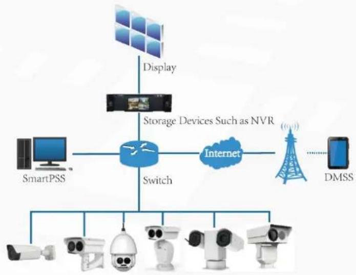
Thermal Hybrid Camera is based on requirements such as temperature measurement, fire prevention, safety protection and night vision. This product can help you view videos, videotape an object, test temperature, warn the potential fire, track a cold/hot spot and analyze a special behavior. This product can be used in energy industry, transportation, building, power system, public security, government, enterprises, and other fields (such as science, education, culture and health). You can use the product alone or combine the product with other storage devices to provide solutions for safety/intelligence city, production safety, safety protection of residential buildings and public area safety.
Features 1.2
- Safe and stable.
With a full embedded system, this Device can implement all-day monitoring in a stable way.
- A long detection distance.
Wide monitoring range and long detection distance. Used for surveillance of wide range and long distance.
• Strong detection ability.
With night vision ability, this Device can clearly distinguish different objects in the dark and can tell camouflage and hidden objects.
• Strong anti-interference ability.
This Device can get rid of interference of light intensity under backlight or strong light environment.
- Adaptive capacity to complex environment.
Applicable to such environment as smoke, smog, rain, snow, and dust which will block your eyes and is very confusing in colors.
This product can be used in various scenarios and the "small application scenarios" is taken as an example here for detailed description. See Figure 1-1.
Application scenarios Figure 1-1
flowchart
graph TD
    A["Display"] --> B["Storage Devices Such as NVR"]
    B --> C["Internet"]
    C --> D["DMSS"]
    E["SmartPSS"] --> F["Switch"]
    F --> G["Camera"]
    G --> H["Camera"]
    H --> I["Camera"]
    I --> J["Camera"]
    J --> K["Camera"]
    K --> L["Camera"]
    L --> M["Camera"]
    M --> N["Camera"]
    N --> O["Camera"]
    O --> P["Camera"]
    P --> Q["Camera"]
    Q --> R["Camera"]
    R --> S["Camera"]
    S --> T["Camera"]
    T --> U["Camera"]
    U --> V["Camera"]
    V --> W["Camera"]
    W --> X["Camera"]
    X --> Y["Camera"]
    Y --> Z["Camera"]
Functions 1.3
Live
Table 1-1 Function description
| Function | Description |
| Real-time preview | You can view both the visible images and thermal images.You can use thermal images to identify an object, and then use visible images to view more details of the object. |
| PTZ operation | For those cameras with PTZ, you can use the PTZ to operate the cameras to enlarge the surveillance range and identify details of an object.You can set a bullet camera's PTZ functions such as preset, tour, pattern, assistant and wiper.You can set a speed dome's PTZ functions such as preset, tour, pattern, horizontal rotation, PTZ speed, free action, boot action and timing task. |
| Voice intercom | For cameras with voice intercom function, you can talk indoors with a person near the outdoor monitor to facilitate problem solution. |
| Snapshot | When previewing, you can snapshot an abnormal image for further check and handling. |
| Local recording | When previewing, you can record abnormal images for further check and handling. |
| Real-time reports | For cameras with temperature measuring, you can check the real-time temperature data of your monitoring area. |
| Real-time spot temperature measurement | For cameras with temperature measuring, you can check the real-time temperature data of any spot in your monitoring area. |
| Laser ranging | For cameras with laser ranging, you can measure the distance between the camera and the object in the middle of the image. |
| Additional functions | Switch video bit stream or streaming protocol.The visible image will be adjusted to the relevant location when you zoom in or out the thermal image.Mark information you need in the surveillance image.Check whether there is any alarm output.Magnify part of the surveillance image. Or, scroll the mouse to zoom the whole surveillance image.You can help the camera focus manually on the web interface.Set a smart rule. When the rule is broken and an alarm is triggered, you can track the target manually.Adjust display effect of the surveillance images.Bot up or shut down the intelligent rule display. |
Playback
Table 1-2 Description of playback function
| Function | Description |
| Videotaping manually | When playing back a video, you can record the key information of the previous video for further check and handling. |
| Planned recording | After you set a recording plan, the system will record automatically. |
| Video playback and download | ● Play back a previous video to find some valuable video fragments.● Download the valuable video fragments for further judgment. |
| Picture playback | Play back pictures you have snapshot to find something valuable. |
| Relay activation | When there is an alarm, the system will videotape automatically. |
Report
You need to follow certain rules such as time sequence to check history data of temperature saved in the device Micro SD card.
Alarm
- Set prompting mode (sound, for example) based on the alarm type.
• View alarm information.
Account Management
Table 1-3 Function description
| Function | Description |
| Management of user group | Add, modify or delete an account group.Manage user permissions based on user groups. |
| User Management | Add, modify or delete a user account.Set the user permissions. |
| Change password | Change users' admin password. |
External Device Management
You can manage your camera's external devices such as heater, fill light and wiper.
Intelligent Thermal Imaging
Table 1-4 Function description
| Function | Description |
| Intelligent Behavior Analysis | Both visible channel and thermal channel have intelligent behavior analysis, including tripwire, area intrusion, abandoned object and missing object.When there is an alarm, you can implement following operations at the same time such as linkage video recording, alarm output, email delivery, PTZ operation and screenshots.Supports addition of detection area and exclusion area. You can also filter disturbances and shadows, save the target objects you need, and lower false alarms caused by ripple on the water surface.For thermal channel, you can set the parameter of misinformation caused by waving water to reduce the misinformation.You can set the tracking mode in the linked tracking function. |
| Fire warning | Both visible channel and thermal channel have fire warning.When there is an alarm, you can implement following operations at the same time such as linkage video recording, alarm output, email delivery, PTZ operation and screenshots. |
| Cold/hot spot tracking | Only thermal channel can implement the cold/hot spot tracking operation.Supports real-time display of surveillance scenario's cold spots and hot spots according to different colors.When there is an alarm, you can implement following operations at the same time such as linkage video recording, alarm output, email delivery, PTZ operation and screenshots. |
| Picture in picture | Only visible channel can implement the picture in picture operation.You can put the thermal image into the visible image. |
Event
Table 1-5 Function description
| Function | Description |
| Video detection | You can implement operation of motion detection and video masking detection.When there is an alarm, you can implement following operations at the same time such as linkage video recording, alarm output, email delivery, PTZ operation and screenshots. |
| Audio detection | Supports detection of input exception and mutation of acoustic intensity.When there is an alarm, you can implement following operations at the same time such as linkage video recording, alarm output, email delivery, PTZ operation and screenshots. |
| Temperature alarm | When temperature satisfies the alarm conditions of temperature testing rules, an alarm is triggered.When there is an alarm, you can implement following operations at the same time such as linkage video recording, alarm output, email delivery, PTZ operation and screenshots. |
| Alarm settings | The alarm is triggered when there is an alarm from external device.When there is an alarm, you can implement following operations at the same time such as linkage video recording, alarm output, email delivery, PTZ operation and screenshots. |
| Abnormality | Supports detection of SD card or network abnormality and illegal access.When there is SD card abnormality or illegal access, you can implement following operations at the same time such as linkage video alarm output, and email delivery.When there is an alarm of network abnormality, you can implement following operations at the same time such as linkage video recording, and alarm output. |
Temperature Measuring Settings
This function is available on select model.
Table 1-6 Function description
| Function | Description |
| Temperature measuring rules | Supports measuring spot, line, polygon and ellipse's average temperature, maximum temperature and minimum temperature.Supports outputting alarm based on different conditions.Supports setting different alarm output conditions to different objects that need to be measured. |
| Temperature contrast | Supports temperature contrast of different objects that needs to be measured.Supports outputting alarm based on different conditions.Supports setting different alarm output conditions to different temperature contrast rules. |
| Heat map | Supports outputting real-time heat map information. Then, you can do the further analysis through the heat map tools. |
| Additional functions | Supports enabling or closing temperature testing rules.Supports enabling or closing isotherm.Supports enabling or closing color code articles. |
Device Initialization 2.1
When using the Device for the first time or after the Device is restored to factory settings, you need to initialize the Device. To initialize the Device, you can log in the web client or use the ConfigTool. Web client is taken as an example for detailed description.

- The Device cannot be used if not initialized.
- To secure your admin account, please keep the password properly and change it regularly.
- Device initialization can be implemented only when the device IP address (192.168.1.108 by default) and the PC IP address are in the same network segment.
____ Open browser, enter camera default IP address in the address bar, and then press Step 1 Enter.

The default IP is 192.168.1.108.
After logging in the device, the Device Initialization interface is displayed. See Figure 2-1.
Device initialization Figure 2-1
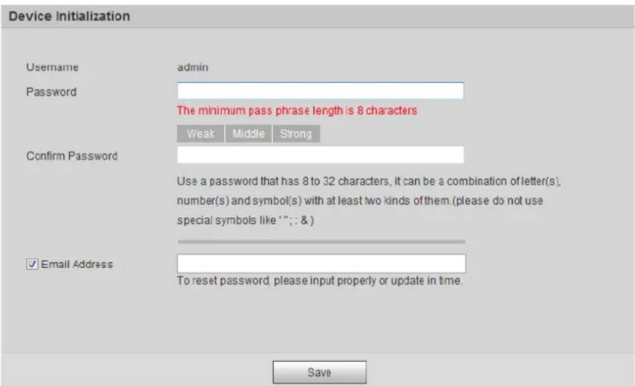
Set the login password of admin user and reserve your phone number. Step 1

- The phone number you have reserved is used for password reset. And this function is set by default. When you forget the password, you need to scan the QR code to reset the password. And the phone number you have reserved will be used to receive the safety code. Then, by the safety code, you can reset the password of admin user.
- If you do not set a number for reservation or you need to change the reserved number, you can follow the path Setting > System Management > User
Management > User Management > User to implement the settings. See "2.4 Resetting Password" for more details.
Step 2 Click Save to complete initialization.
After you have initialized the Device, if the Online Upgrading is displayed, please operate according to the interface prompts.
Modifying IP Address 2.2
Default IP address of all devices is 192.168.1.108. When you use the Device for the first time or there is change of the network, modify IP address of your device according to network planning.
You can modify one or several IP addresses through ConfigTool. You can also log in the web client to modify IP addresses.
2.2.1 Modifying One IP Address
When there are only a few devices or the login passwords of devices are different, you can modify only one IP address at one time. Logging in WEB client to modify IP addresses is taken as an example for detailed description.
Log in web interface from the IE browser. Step 1

• The default IP is 192.168.1.108.
- The default user is admin. The password is the one that was configured during initial settings.
Select Setting > Network > TCP/IP. Step 2
The TCP/IP interface is displayed. See Figure 2-2.
TCP/IP interface Figure 2-2

Configure relevant information of IP address and then click Save. Step 3
2.2.2 Modifying Several IP Addresses
When there are several devices or the login passwords of devices are the same, you can modify several IP address at the same time through the ConfigTool.
Preparation
- You have obtained the installation package of ConfigTool. To obtain the installation package, you can consult technical support staffs.
- You have achieved network communication between PC (which is with ConfigTool) and the Device.
Procedure
Click

The Modify IP interface is displayed.
(No text)
Click Search Settings. Step 2
The dialog box named by "settings" is displayed.
The Ground Truth image displays a single, solid horizontal line. According to Rule 2 (UNDERSCORE & LINE RULES), if the GT contains lines used for stylistic emphasis or as background (like ruled paper), the OCR result must ignore them. The line in the GT is clearly a stylistic or background line, not a placeholder for text. Therefore, the OCR should not have output any underscores. Outputting `____` constitutes an error under Rule 2, as it hallucinates placeholder symbols where none are semantically intended. Hence, the OCR result is inconsistent with the Ground Truth.
Set the network segment of the Device, admin and password. Then click OK. Step 3
After the search, the system displays devices that have been searched.

Default user name and password are both admin.
The Ground Truth image displays a single, solid horizontal line. According to Rule 2 (UNDERSCORE & LINE RULES), if the GT contains lines used for stylistic emphasis or as background (like ruled paper), the OCR result must ignore them. The line in the GT is clearly a stylistic or background line, not a placeholder for text. Therefore, the OCR should not have output any underscores. Outputting `____` constitutes an error under Rule 2, as it hallucinates placeholder symbols where none are semantically intended. Hence, the OCR result is inconsistent with the Ground Truth.
Select devices whose IP address needs to be modified and click the icon indicating that Step 4 you can modify several IP addresses at one time.
The dialog box of Modify IP Address is displayed. See Figure 2-3.
Modifying IP address Figure 2-3

(No text)
Select the mode of IP address based on the actuality. Step 5
- DHCP mode: When there is a DHCP server in the network, set the Mode as DHCP and the Device obtains IP addresses from the DHCP server automatically.
- Manual mode: Set Mode as Static and enter Starting IP, Subnet Mask and Gateway. Then, IP addresses of devices are incrementally modified from the start IP address.

Select the check box of The Same IP and set the IP addresses of the Devices you have picked up as the same one.
____ Click OK to finish configuration. Step 6
Logging in Web Interface 2.3
After you have modified the IP addresses, you can log in the WEB interface of the Device through a browser to operate, configure and maintain the Device.
Background Information
To log in the Device in a smooth way, you need to make sure that the PC connected to the Device satisfies the following requirements. See Table 2-1.
Table 2-1 Recommended PC configuration
| PC items | Recommended configuration |
| Operation system | ≥ Windows 7 |
| CPU | ≥ Intel core i3 |
| Graphics card | ≥ Intel HD Graphics |
| Storage | ≥ 2GB |
| Display | ≥ 1024×768 Resolution |
| Browser | Internet Explorer 9/10/11 |
Procedure
____ Open browser, enter IP address in the address bar, and then press Enter. Step 1 The login interface is displayed. See Figure 2-4.
Login Figure 2-4
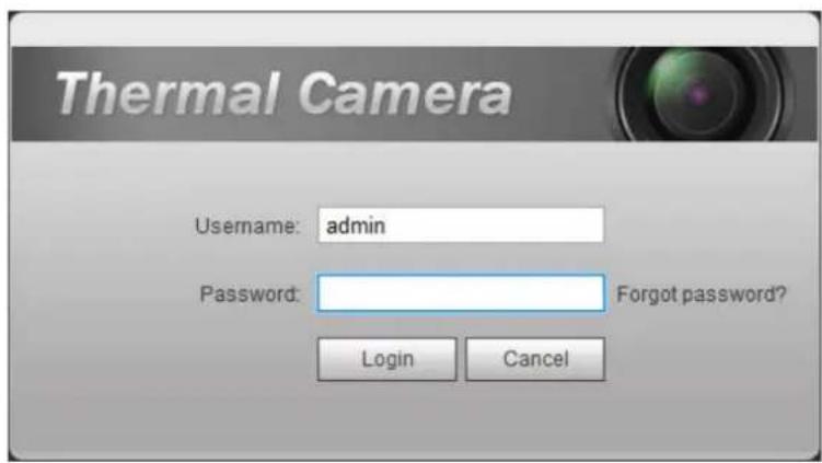
Enter username and password, and click Login. Step 2
After the successful login, the Live interface is displayed. See Figure 2-5.

- The default user is admin. The password is the one that was configured during initial settings.
- It will prompt you to install plug-in for the first system login. Please download and install plug-in according to the prompt.
- Functions of different devices might vary, and the actual product shall prevail.
Live Interface Figure 2-5
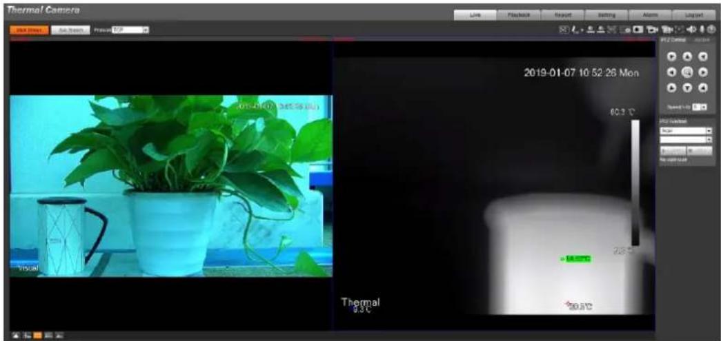

Click Log out on the upper right corner to exit the interface.
Resetting Password 2.4
If you forget the password, you can use the reserved E-mail address to achieve password resetting.
Step 1 Open IE browser and type the camera's IP address. Then press Enter. The Thermal Camera interface is displayed. See Figure 2-6.
Logging in the Device Figure 2-6

____ Click Forgot Password? Step 2
The Reset the password (1/2) interface is displayed. See Figure 2-7.
Reset the password(1/2) Figure 2-7

Reset the password. Step 3
Scan the QR code, and the security code will be sent to the email address you have already fulfilled. Type the security code then.

- Reset the password in time when you receive the security code, because the security code will be invalid within 24 hours.
- If you get security codes twice but do not use them, when you get the security code for the third time, the system will prompt failure. To solve this problem, you need to restore your device to default settings or wait 24 hours to get a new one.
Click Next. Step 4
The Reset the password (2/2) interface is displayed. See Figure 2-8.
Resetting the password(2/2) Figure 2-8
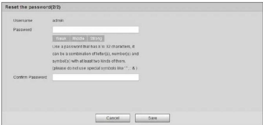
Fill in a new password and confirm it. Step 5
The password is made up of characters for 8–32 digits and the password must contain two of the three forms (number, letter, and the common characters. “”、“”、“;”、“.”、“&” are not included.) You should obey the prompt of the password’s security level and set a password with high security level.
Click Save to finish password resetting. Step 6
The login interface is displayed.
Live 3.1
On the Live interface, you can do operations to the real-time surveillance images such as viewing, taking snapshots and recording videos.

• Functions of different devices might vary, and the actual product shall prevail.
- Image channel with a box around it is the one that has been chosen. All your operation is valid only to this channel.
- Double-click an image channel and the image channel is displayed in a full video display area. Double-click the image channel again and the channel will be displayed in a full screen. Then, right-click the full-screen image and the image returns to its previous state.
3.1.1 Introduction to Live Interface
Click the Live tab, and the Live interface is displayed. See Figure 3-1. In the live interface, there are five function bars. See Table 3-1.
The live interface Figure 3-1
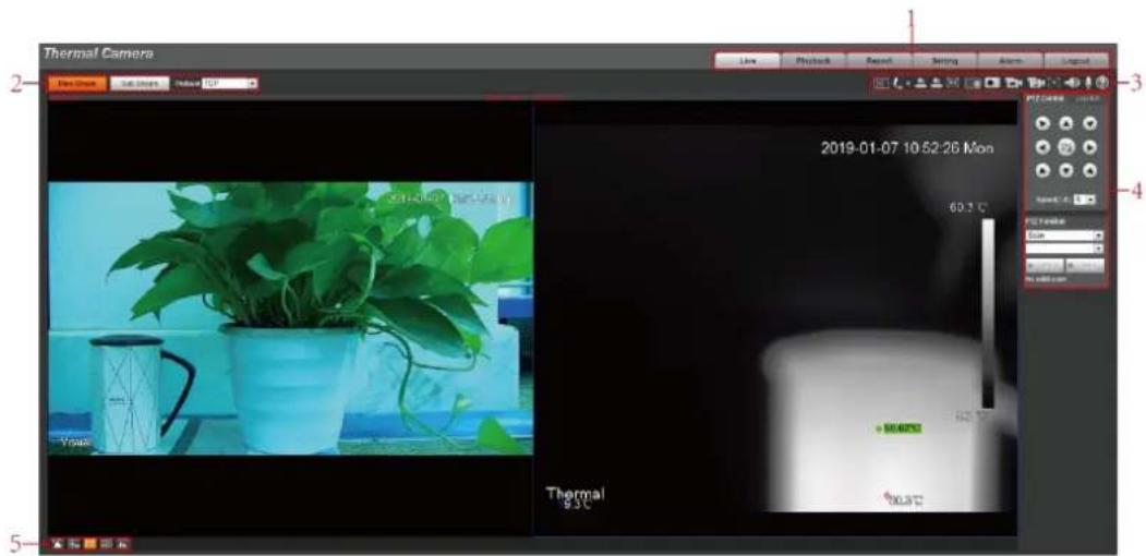
Table 3-1 Description of function bar
| No. | Name | Description |
| 1 | System menu | Click each function tab in the system menu to go to the corresponding interface. |
| 2 | Encode bar | Select bit stream type and streaming protocol when previewing a video.Main Stream: It has large bit stream value and image with high resolution, but also requires large bandwidth. This option is normally used for storage and surveillance.Sub Stream: It has small bit stream value and smooth image, and requires little bandwidth. This option is normally used to replace main stream when bandwidth is not enough.Streaming protocol: A network transmission protocol, supports TCP, UDP and Multicast. |
| 3 | Live view function bar | For functions and operations of live view bar, see "3.1.2 Function Bar." |
| 4 | PTZ control | For details of PTZ control, see "3.2 PTZ." |
| 5 | Adjustment bar of video window | Supports adjusting clarity of video images, displaying intelligent rules, zooming with focusing at the same time, checking real-time reports.See "3.1.3 Window Adjustment" for details. |
3.1.2 Function Bar
See Figure 3-2 and Table 3-2 for more details.

Functions of different devices might vary, and the actual product shall prevail.
Live view function Figure 3-2

Table 3-2 Live view function description
| No. | Name | Description |
| 1 | Regional focus | Click this icon, and click or draw a box on the video image. Then the camera will implement auto focus. |
| 2 | Mark pen | Click to mark a target on the video image and the default pen color is red.Click to switch the pen color from red, green and blue.Marks are not carried in video recordings. |
| 3 | Relay-out | Shows alarm output state. Click the icon to force enable or force disable alarm output.Alarm output state description:Red: Alarm output.Grey: Alarm over. |
| 4 | Fixed Focus | Click this icon. Then the visible image adjusts its values of zoom and focus in accordance with values of the thermal image. |
| 5 | Zoom in | You can zoom in video image with two operations:Click the icon to enlarge part of visible light or thermal images.Right-click to resume.Click the icon to zoom a video image by scrolling the mouse. |
| 6 | Snapshot | Click the icon to capture a live image and save it under the path you have set.To check or modify the storage path, see "4.7.2.1 Configuring Storage Path." |
| 7 | Single-lens video recording | Select visible image or thermal image. Then click this icon to start video recording.To check or modify the storage path, see "4.7.2.1 Configuring Storage Path." |
| 8 | Double-lens video recording | If you want to record both visible image and thermal image at the same time, click this icon. And, when you play the videos, videos of both visible image and thermal image will be played. |
| 9 | Easy focus | Only thermal image supports easy focus.Click this icon. Then you can see the two parameters of AF Peak and AF Max.AF Peak: The live image clarity value.AF Max: The best image clarity value.The closer AF Peak is to AF Max, the better the focusing effect. Easy focus will be disabled after five minutes. |
| 9 | Audio | Click the icon to enable or disable audio output.This function is available on select model. |
| 10 | Voice intercom | Click this icon to enable or disable the intercom function.Please open stereo remix after enable the voice intercom function.This function is available on select model. |
| 11 | Help | Click to open help document. |
3.1.3 Window Adjustment

Functions of different devices might vary, and the actual product shall prevail.
Window adjustment (dome camera and PTZ camera) Figure 3-3

Window adjustment (bullet camera) Figure 3-4

3.1.3.1 Image Adjustment
Adjust brightness, contrast, hue and saturation of video images on your web.

For detailed operations, see "4.1.1 Configuring Lens."
Click 📄, and the Image Adjustment interface is displayed at the right side of live interface. See Figure 3-5.
Image adjustment interface Figure 3-5
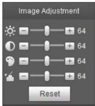
Table 3-3 Image adjustment configuration
| Icon | Function | Description |
 | Brightness | Adjusts the overall image brightness, change the value when the image is too bright or too dark. The bright and dark areas will have equal changes. |
 | Contrast | Change the value when the image brightness is proper but contrast is not enough. |
 | Hue | Makes the color deeper or lighter. The default value is made by the light sensor and is recommended. |
 | Saturation | Adjusts color depth. This value doesn't change the overall image brightness. |
 | Reset | Click the icon to reset brightness, contrast, hue and saturation to their default values. |
3.1.3.2 Display of Smart Rules
You can control whether rules information is displayed on surveillance images. It is set by default that this function is in opening state.
Click 📋 to select Enable, and then select Enable to display smart rules and detection box; select Disable to stop.
3.1.3.3 Zoom and Focus

Zooming and focusing functions are only available on motorized vari-focal devices.
Adjust focal length of your lens to zoom in or out surveillance images; adjust optical afterfocus of your lens to improve clarity level of video images.
Click, and the zooming and focusing interface is displayed at the right side of live interface.
- Select the visible channel and you can zoom, focus and change the aperture.
- Select the thermal channel and you can zoom and focus.
Table 3-4 Zoom and focus description
| Parameters | Description |
| Variable focal length | Click  and and  t the optical back focal length of thermal tunnel to make images more clear. t the optical back focal length of thermal tunnel to make images more clear. |
| Auto focus | Auto focus. |
3.1.3.4 Optical Axis Calibration
Used only for calibrating the device lens when the Device is being debugged in the factory. You do not need to operate this function.
3.1.3.5 Real-time Reports
Within the set time, record the average temperature of the presets, lines and area that you have selected.

Only Devices with temperature-measuring function support this function, and the actual product shall prevail.
Preparation
You have set the temperature measuring rules. For detailed operation, see "4.6.1.1 Configuring Temperature Measuring Rules."
Procedure
Click and the real-time reports interface is displayed. Select the temperature-measuring program and set the time circle. Then the real-time temperature change is displayed. See Figure 3-6.
Temperature recording area Figure 3-6

3.1.4 More Functions
3.1.4.1 Real-time Spot Temperature Measuring

Only devices with temperature-measuring function support this function, and the actual product shall prevail.
Move the pointer to any position of the video image and click. Then the real-time temperature of this spot is displayed. See Figure 3-7.
Real-time spot temperature measuring Figure 3-7

3.1.4.2 Laser Ranging

- Only device with laser ranging can implement this operation and the actual interface shall prevail.
- Laser ranging does not perform well to those objects (such as glass and marble) with strong reflection ability. During laser ranging, select those objects with rough surface as your target.

Mind the distance during laser ranging. Less than 50 m will result in a damaged laser.
Click Start Ranging, and the camera starts to measure the distance from itself to the object in the middle of the image (as indicated with the red cross sign).
PTZ 3.2
3.2.1 Bullet Camera

PTZ setting of bullet camera is used for controlling external PTZ device. Connect the Device to external PTZ through RS-485 port before using this function.
3.2.1.1 Configuring Protocol
If you want to control the external PTZ by your bullet camera, you need to set the PTZ protocol first and then connect PTZ to your camera.
Select Setting > System Management > PTZ Setting. Step 1
The PTZ Settings interface is displayed. See Figure 3-8.
PTZ settings Figure 3-8

Configure PTZ parameters. For detailed description, see Table 3-5. Step 2
Table 3-5 Parameter description
| Parameter | Description |
| Protocol | Matches with the PTZ protocol. |
| Address | Enter the corresponding device address.[IMAGE]The entered address must be the same with the address configured on the PTZ; otherwise the PTZ cannot be controlled from the bullet camera. |
| Baud rate | Configure device baud rate. |
| Data bit | The default is "8". |
| Stop bit | The default is "1". |
| Parity | The default is "none". |
3.2.1.2 Configuring PTZ Functions

- The protocol setting has been completed. For detailed operations about protocol setting, see "3.2.1.1 Configuring Protocol".
- For images representing the effect of external PTZ, you need to preview on the preview images of the external PTZ, not on the preview image of the bullet camera.
- The following functions are available only when your bullet camera is connected to the external PTZ.
3.2.1.2.1 Configuring Scan
The camera scans on the horizontal direction between the left and right borders.
Step 1 Click the PTZ tab and select Scan in the PTZ function setting list.
Linear sweep Figure 3-9

____ Type the scan number and set the left and right border. Step 2
1) Through the direction button, move the camera to the left border that you want and click Set Left.
2) Through the direction button, move the camera to the right border that you want and click Set Right.
Click Start to start scan; click Stop to end it. Step 3
3.2.1.2.2 Configuring Presets
By configuring presets, the camera can store parameters such as PTZ's horizontal angle, inclination angle, and the lens focal length under the current situation to the Device. If you need those parameters later, you can quickly adopt them and adjust the PTZ and camera to those locations.
Step 1 Click the PTZ tab and select Preset in the PTZ Function setting list.
Preset Figure 3-10

____ Through the direction button, move the camera to the surveillance direction that you Step 2 need.
Step 3 In the preset box, type the preset number.

Range of the preset number is limited by the PTZ protocol.
Click Add to add a preset. Step 4
Enter a preset number and click Go to. The camera turns to the corresponding Step 5 position.
3.2.1.2.3 Configuring Tour
By configuring tour, you can put the presets to the auto tour to make the camera move back and forward quickly and automatically according to the presets.
Preparation
You have set several presets.
Procedure
Step 1 Click the PTZ tab and select Tour in the PTZ Function setting list.
In the tour typing box, type the tour number. Step 2

Range of the preset number is limited by the PTZ protocol.
In the preset typing box, type the preset number. Step 3
Step 4 Click Add Preset to add a preset in the tour.
Repeat step 3 to step 4 to add several presets in the tour.

Type a preset number and click Delete Preset to delete preset it in the tour group.
Step 5 Type a tour number. Click Start to start touring; click Stop to end it.
3.2.1.2.4 Configuring Pattern
By configuring pattern, you can record continuously your operation to the PTZ and record the moving pattern of the camera's lens. The Device will make the location where the recording begins as the beginning point, and move back and forward automatically following the preset movement pattern.
Step 1 Click the PTZ tab and select Pattern in the PTZ Function setting list.
In the pattern typing box, type a pattern number.

Range of the pattern number is limited by the PTZ protocol.
Click Start Rec. Step 2
Step 3 By operating the PTZ control panel, you can control the camera's surveillance direction, zoom images or change the focal length.
Step 4 Click Stop Rec to complete setting of the pattern.
Step 5 Select a pattern number. Click Start to start pattern; click Stop to end it.
3.2.1.2.5 Turing on Wiper
Step 1 Click the PTZ tab and select Wiper in the PTZ Function setting list. See Figure 3-11. Wiper Figure 3-11

Step 2 Click Enable to enable the wiper; click Disable to disable it.
3.2.1.3 Operating PTZ

- The corresponding protocol setting and function setting have been completed. See "3.2.1.1 Configuring Protocol" and "3.2.1.2 Configuring PTZ Functions" for more details.
- For images representing the effect of external PTZ, you need to preview on the preview images of the external PTZ, not on the preview image of the bullet camera.
Click the PTZ tab and the PTZ control panel is displayed on the right side of the PTZ interface. See Figure 3-12.
PTZ control panel Figure 3-12

Table 3-6 Parameter description
| No. | Function | Description |
| 1 | Direction button | Eight directions are contained: up, down, left, right, upper left, upper right, lower left, and lower right. |
| 2 | Speed | Controls the movement speed. The bigger the value is, the faster the movement will be.With this function, you can also change the speed of adjusting the PTZ direction, zooming, changing the focal length and adjusting the aperture. |
| 3 | Zoom, focus and iris | Click  the zoom, focus and iris' value becomes bigger; click the zoom, focus and iris' value becomes bigger; click  the zoom, focus and iris' value becomes smaller. the zoom, focus and iris' value becomes smaller. |
| 4 | PTZ function | For detailed operations of PTZ, see "3.2.1.2 Configuring PTZ Functions." |
3.2.1.4 Configuring Preset Backup
You can export presets you have set to back them up. When you need those presets, you can import them to your device and restore them.

If you want to export or import presets, you have to obey the following steps.
Select Setting > PTZ > Preset Backup. Step 1
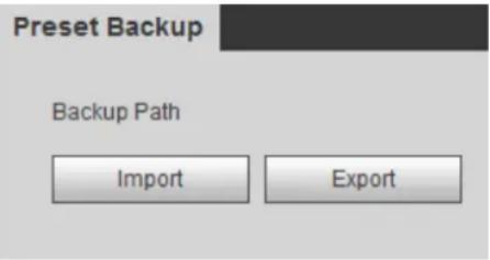
The Preset Backup interface is displayed.
Preset backup Figure 3-13
____ Export or import presets. Step 2
- Click Export to export presets for backup.
- Click Import to import presets you have already backed up
3.2.2 Dome Camera
3.2.2.1 Configuring Protocol
For external devices (such as network keyboard, NVR), if you want to use them to control the dome camera or its PTZ, you need to set the protocol to connect the external devices to the dome camera or its PTZ first.
Select Setting > PTZ > Protocol. Step 1
The Network PTZ interface is displayed. See Figure 3-14.
Network PTZ setting Figure 3-14

Select the protocol that is matched with the camera. Step 2
____ Click Save to finish configuration. Step 3
3.2.2.2 Configuring PTZ Functions
Select Setting > PTZ > Function and the Function interface is displayed.
It's set by default that the thermal image is displayed. In the thermal image, you can click

to switch the image to visible image. And, in the visible image, you can click 📄 to switch the image to thermal image.
3.2.2.2.1 Configuring Preset
By configuring presets, the camera can store parameters such as PTZ's horizontal angle, inclination angle, and the lens focal length under the current situation to the Device. If you need those parameters later, you can quickly adopt them and adjust the PTZ and camera to those locations.
Select Setting > PTZ > Function. Step 1
The Preset interface is displayed. See Figure 3-15.
The preset interface Figure 3-15

Configure preset. Step 2
1) Click Add to add a new preset.
2) Operate the PTZ control panel to move the camera lens to a specific direction you need.
3) Double-click the preset's Number to modify it.
Some presets are already endowed with fixed and special functions by this camera producer. See Table 3-7. If you want to use those functions, you can set these presets' No. to be the Number.
Table 3-7 Function description of the very presets
| Preset No. | Description |
| 21 | Enable this preset. Then the camera will automatically turn off the fill light under color image and turn it on under black/white image. |
| 67 | Enable this preset and the laser current will be increased. |
| 68 | Enable this preset and the laser current will be decreased. |
| 69 | Enable this preset and the camera will automatically switch the image from color mode to black/white mode under low lighting condition. |
4) Double-click the preset's Preset Title to modify it. Then click 🔒 to finish configuration.


Click - to delete a preset that is wrongly configured or that is not needed anymore.
- Click Delete to delete all the presets you have added.
3.2.2.2.2 Configuring Tour
By configuring tour, you can put the presets to the auto tour group to make the camera move back and forward quickly and automatically according to the presets.
Preparation
You have set several presets.
Procedure
Step 1 Select Setting > PTZ > Function > Tour.
The Tour interface is displayed. See Figure 3-16.
The tour interface Figure 3-16

Configure tour. Step 2
1) Click Add to add a tour.
2) Click Add to add a preset.
Click repeatedly to add several presets.
3) Double-click to select a preset. And double-click to configure the lasting time.
4) Double-click the touring name that you have added to modify it. Click Save to finish configuration.

Click to delete a tour or a preset.
Select a tour and click Start to start camera tour. Step 3 Click Stop to stop the tour.
3.2.2.2.3 Configuring Scan
You can configure an arc and horizontal area for your camera PTZ's rotation. Then by giving your PTZ a fixed rotation speed, you can get your camera scan from left to right (and from right to left) at a fixed speed.
Step 1 Select Setting > PTZ > Function > Scan.
The Scan interface is displayed. See Figure 3-17.
The scan interface Figure 3-17

Configure scan. Step 2
1) Select a Scan No. and set its Speed.
2) Click Setup.
Buttons of Set Left Limit and Set Right Limit are displayed.
3) Operate the PTZ control panel and move the camera to a left border you want and click Set Left Limit; move the camera to a right border you want and click Set Right Limit.
Step 3 Select a Scan No. and click Start to start scan.
Click Stop to stop the scan.
3.2.2.2.4 Configuring Pattern
The function of "pattern" can record continuously the user's manual operation to the PTZ and record the moving tracking of the camera's lens. The camera will make the location where the recording begins as the beginning point, and move back and forward automatically following the preset movement pattern.
Select Setting > PTZ > Function > Pattern. Step 1
The Pattern interface is displayed. See Figure 3-18.
The pattern interface Figure 3-18

Configure pattern. Step 2
1) Select a Pattern No.
2) Click Setup.
Buttons of Start Rec and Stop Rec are displayed.
3) Click Start Rec.
4) Operate the PTZ control panel and adjust you camera's direction, zoom and focus.
5) Click Stop Rec to finish configuration.
Step 3 Select a Pattern No. and click Start to start pattern.
Click Stop to stop the pattern.
3.2.2.2.5 Configuring Pan
You can enable this function and get your camera PTZ rotate horizontally for 360^ at a fixed speed all the time.
Select Setting > PTZ > Function > Pan. Step 1
The Pan interface is displayed. See Figure 3-19.
The pan interface Figure 3-19

Step 2 Set a Pan Speed. Click Start to start pan.
Click Stop to stop the pan.
3.2.2.2.6 Configuring PTZ Speed
PTZ speed is determined by two factors—firstly and basically, the speed level (low, middle and high, marked by ① in Figure 3-20); secondly, the control panel's speed value (1, 2, 3...8 marked by ② in Figure 3-20). If you select Low as the PTZ Speed ①, then according to the maximum Low value, the Speed② will be divided into 8 parts, and it's the same for you to select Middle or High as the PTZ Speed ①.
Select Setting > PTZ > Function > PTZ Speed. Step 1 The PTZ Speed interface is displayed. See Figure 3-20.
PTZ speed Figure 3-20

Step 2 Select from Low, Middle and High. The configuration takes effect immediately.
3.2.2.2.7 Configuring Idle Motion
Enable this function. And when there is a time period when PTZ does not receive any instructions, motions you have already set will be implemented.
Preparation
You have configured preset, tour, scan and pattern before configuring idle motion.
Procedure
Select Setting > PTZ > Function > Idle Motion. Step 1 The Idle Motion interface is displayed. See Figure 3-21.
The idle motion interface Figure 3-21

Configure idle motion. Step 2
1) Select the Enable check box to enable this function.
2) Select an idle motion and set idle time.

After you have set a value of idle time, when the time when you do not operate the PTZ is longer than that value, the idle motion will be implemented immediately.
3) Click Save to finish configuration.
3.2.2.2.8 Configuring Power Up
If you want the PTZ to implement certain actions after the camera is powered, configure this function.
Select Setting > PTZ > Function > Power Up. Step 1 The Power Up interface is displayed. See Figure 3-22.
Power up Figure 3-22

Select the Enable check box. Step 2
Select the Power Up actions. Step 3

Select Auto and the PTZ will continue to implement the action before the power is off.
Click Save to finish configuration. Step 4
3.2.2.2.9 Configuring Time Task
You can configure a time task and let camera implement certain actions within the period you have set.
Preparation
You have configured preset, tour, scan and pattern before configuring time task.
Procedure
Select Setting > PTZ > Function > Time Task. Step 1 The Time Task interface is displayed. See Figure 3-23.

Configure time task. Step 2
1) Select the Enable check box to enable this function.
2) Select a Time Task Num.
3) Select a Time Task Action from Preset, Tour, Scan and Pattern.

When you set Preset as Time Task Action, the Action Number selection box is displayed. You can select the action number based on your needs.
4) In the Auto Home selection box, set the time for the camera to return to its previous condition.

Auto home time: Time for your camera to return to its previous condition and continue the time task when the time task is interrupted by human operation.
5) Click Period Setting to set the detailed period for a time task.
6) Click Save to finish configuration.
(Optional) Copy a time task. Step 3
Copy task information you have configured to other tasks.
1) Select a Time Task Num you have already configured.
2) In Copy To Task No., select a task number to be configured.
3) Click Copy.
4) Click Save to finish task copy.
3.2.2.2.10 Restarting PTZ Manually
Select Setting > PTZ > Function > PTZ Restart. Step 1
The PTZ Restart interface is displayed. See Figure 3-24.
The PTZ restart interface Figure 3-24

Click PTZ Restart. PTZ restarts. Step 2
3.2.2.2.11 Restoring PTZ to the Default Settings

The operations below will delete all the PTZ settings you have configured. Please be cautious.
Select Setting > PTZ > Function > Default. Step 1
The Default interface is displayed. See Figure 3-25.
The default interface Figure 3-25

Click Default. Step 2 All your PTZ settings are restored to the default ones.
3.2.2.3 Operating PTZ

The corresponding protocol settings and function settings have been completed.

Table 3-8 Parameter description
| No. | Function | Description |
| 1 | Direction button | Eight directions are contained: up, down, left, right, upper left, upper right, lower left, and lower right. |
| 2 | Speed | Controls the movement speed. The bigger the value is, the faster the movement will be.With this function, you can also change the speed of adjusting the PTZ direction, zooming, changing the focal length and adjusting the aperture. |
| 3 | Zoom, focus and iris | Click and the zoom, focus and iris' value becomes bigger; click and the zoom, focus and iris' value becomes smaller. |
| 4 | PTZ function | For detailed operations of PTZ, see "3.2.1.2 Configuring PTZ Functions." |
3.2.2.4 Configuring Preset Backup
You can export presets you have set to back them up. When you need those presets, you can import them to your device and restore them.

If you want to export or import presets, you have to obey the following steps.
Select Setting > PTZ > Preset Backup. Step 1
The Preset Backup interface is displayed.
Preset backup Figure 3-27

____ Export or import presets. Step 2
- Click Export to export presets for backup.
- Click Import to import presets you have already backed up
Playback 3.3
Playback of both videos and pictures is supported.

Functions of different devices might vary, and the actual product shall prevail.
Click the Playback tab, and the Playback interface is displayed. See Figure 3-28.
Playback Figure 3-28

3.3.1 Video Playback
3.3.1.1 Interface Layout
Select dav in the File Type list, and the video playback interface is displayed. See Figure 3-29. On the Playback interface, there are seven function bars. See Table 3-9.
Video playback Figure 3-29
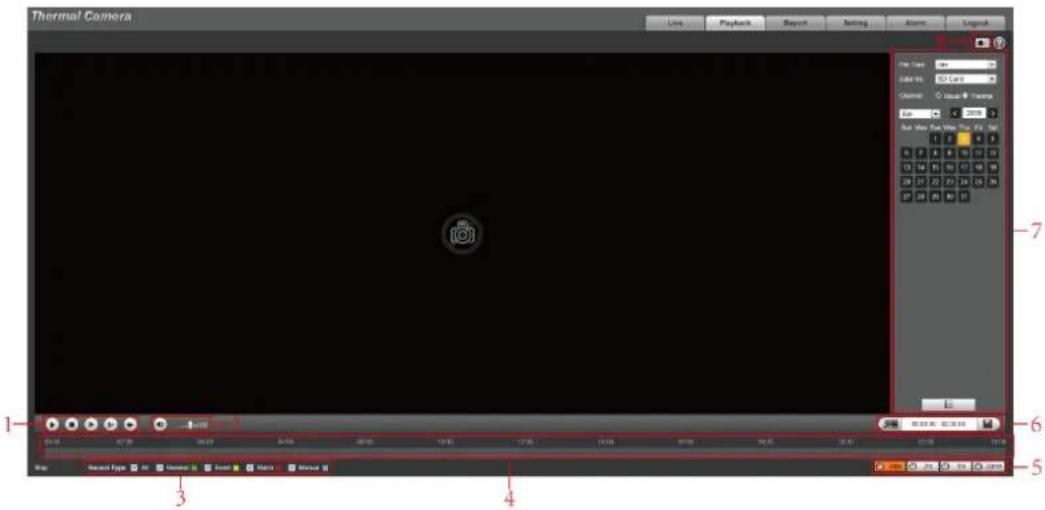
Table 3-9 Function bar description
| No. | Functions | Description |
| 1 | Playback control bar | For detailed information about control buttons, see "3.3.1.2 Operate Control Bar." |
| 2 | Volume adjustment | Controls playback volume. r^ d . r^ d . r^ d , and the volume can be adjusted. d , and the volume can be adjusted. |
| 3 | Record type | Record type includes All, General, Event, Alarm, and Manual.You can select according to your actual needs. |
| 4 | Time bar | Displays the record type and the time period.Click any point in the colored area, and the playback starts from this moment.Each color represents a certain video type, and the corresponding relationship is indicated in the record type selection area. |
| 5 | Time bar unit | [c3z4]  bar has 24 hours. bar has 24 hours. |
| 6 | Video clip | Clip and save certain video section. For detailed operations, see "3.3.1.4 Clipping Recorded Video." |
| 7 | Playback file list | You can select file type, data source and record date. |
| 8 | Snapshot | Click the icon to capture a live image and save it under the path you have set. |
3.3.1.2 Operate Control Bar
See Table 3-10 for details.
Table 3-10 Playback control bar
| Icons | Functions | Description |
 | Play | Click this icon to play video. |
 | Stop | Click this icon to stop playback. |
 | Play by Frame | Click this icon to play the next frame.You need to pause the playback before using play by frame. |
 | Slow playback | Click this icon to slow down the playback. |
 | Fast playback | Click this icon to speed up the playback. |
3.3.1.3 Playing Back Videos
There are differences in operation of video playback according to the differences of data sources. Data come from SD card or your local storage.
3.3.1.3.1 Playing Back Videos in SD Card
Select record type in the Data Src bar. See Figure 3-30. Step 1
Selecting record type Figure 3-30

Step 2 In the File Type box, select .dav, and in the Data Src box, select SD Card. See Figure 3-31.
File type contains dav and jpg. "Dav" represents video playback and "jpg" represents picture playback.
Setting files playback Figure 3-31

Those dates with blue color indicate there are recorded videos in those days. Select a Step 3 date with recorded video inside and its time bar is displayed.
Each color on the time bar represents a certain record type. See the matching relationship in Figure 3-30.
Step 4 Play video.
- Click in the playback control bar.
The system plays the recorded video of the selected date (in time order).
- Click any point in the colored area of the time bar. See Figure 3-32.
The playback starts from that point.
Time bar Figure 3-32

- Click ☐, and the video files of the selected date will be listed. Double-click a file in the list. See Figure 3-33. The system plays the video and displays file size, start time and end time.
For detailed operations, see Table 3-11.
List of playback files Figure 3-33

Table 3-11 Picture Playback file more operations
| Operation | Description |
| Search | Enter start time and end time, and then click 📄 to find out all the video filesbetween the entered start time and end time. |
| Download | Select dav or mp4 in the Download Format. Then clickThe file will be downloaded to the set storage path. For detailed operations of setting the storage path, see "4.1.2.5 Configuring Storage Path."Downloading and playing video at the same time is not supported. |
| Back | Click to go back to the calendar interface. |
3.3.1.3.2 Playing Back Local Videos
Step 1 In the Data Src box, select video type. See Figure 3-30.
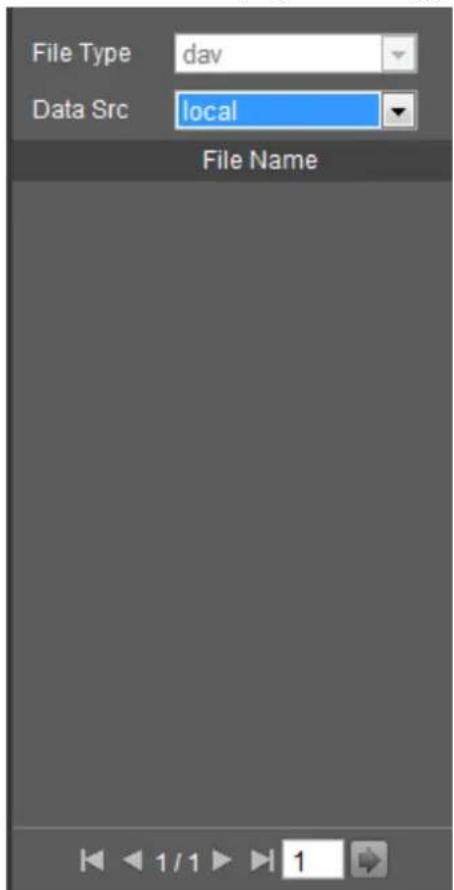
Step 2 Select dav in File Type, and Local in Data Src.
List of playback files is displayed. See Figure 3-34.
List of playback files (2) Figure 3-34
Double-click a file and the file is displayed. Step 3
3.3.1.4 Clipping Recorded Videos
You can clip a part of recorded video and save it under the path you have set. See Figure 3-35.
Video clipping Figure 3-35

____ Click on the time bar to select the start time, and then click to start. Step 2
____ Click again on the time bar to select the end time, and then click to finish. Step 3
Click Step 4
The system prompts that you cannot play back and download a recorded video at the same time.
Click Save. Step 5
The system stops playback and save the edited file under the storage path you have set. For detailed operations of setting the storage path, see "4.1.2.5 Configuring Storage Path".
3.3.2 Picture Playback
The following content is about the introduction of the interface function bar and how to play back pictures.
3.3.2.1 Interface Layout
Select "jpg" in "file type" list, and the Picture Playback interface is displayed. See Figure 3-36.
Image playback Figure 3-36

Table 3-12 Image playback
| No. | Function | Description |
| 1 | Control button for playing pictures | Includes the following two types:When this icon displays, the picture playback is paused or not started. Click this icon to start picture playback.When this icon displays, the picture playback is ongoing. Click this icon to stop picture playback.The two states above can be switched. |
| 2 | Snapshot type selection | There are three types including General, Event and Alarm, and you can select one of them according to actual needs. |
| 3 | Playback file list | You can select file type and snapshot data. |
3.3.2.2 Picture Playback
You can check and play a snapshot image based on your own needs.
Select a snapshot type in the selection bar of snapshot type. See Figure 3-37. Step 1
Snapshot type selection Figure 3-37

Step 2 Select jpg in File Type. See Figure 3-38.
File type contains dav and jpg. "Dav" represents video playback and "jpg" represents image playback.
Configuring playback files Figure 3-38

Those dates with blue color indicate there are snapshot images in those days. Select a Step 3 date with snapshot images inside.
____ Play images. Step 4
- Click ▶ in the play control bar and the system plays the snapshots you have selected (in time order).
- Click which represents the file list, pictures which you have selected would be displayed. Double-click a file in the list. See Figure 3-39. The file is displayed.
For detailed operations, see Table 3-13.

Table 3-13 Picture Playback file more operations
| Operation | Description |
| Search | Enter starting time and ending time, and click [IMAGE]Finds out all the picture files between the entered starting time and ending time. |
| Download | Click , and the file is downloaded to local host.[IMAGE]The download operation might vary with different browsers, and the actual interface shall prevail. |
| Back | Click [←] to go back to the calendar interface. |
Reports 3.4
You can follow certain rules such as time sequence, and check history data of temperature saved in the device Micro SD card.
Preparation
- You have set the temperature measuring rules (spots, lines and area included). For detailed operations, see "4.6.1.1 Configuring Temperature Measuring Rules".
- You have inserted a SD card to the Device.

Some devices do not support this function. The actual product shall prevail.
Procedure
Click the Report tab. Step 1
The Report interface is displayed. See Figure 3-40.
Figure 3-40 Report
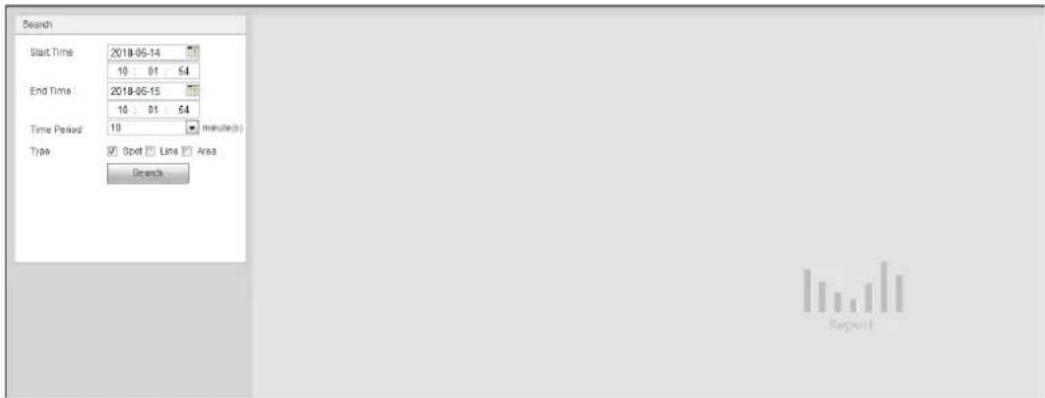
Set the conditions for searching and click Search. Step 2
Temperature data you have searched is displayed. See Figure 3-41.
Result of report searching Figure 3-41

Alarm 3.5
You can select alarm type as needed, when the selected alarms are triggered, the system would record detailed alarm information at the right side of the interface.

Function of different devices might vary, and the actual product shall prevail.
3.5.1 Introduction to Alarm Types
For alarm types and conditions that trigger an alarm, see Table 3-14.
Table 3-14 Alarm type description
| Alarm Type | Description | Condition |
| Motion detection | The alarm is triggered when moving objects are detected. | You have enabled motion detection. For detailed operations, see "4.5.1 Configuring Video Detection." |
| Disk full | The alarm is triggered when the free space in the SD card is lower than the set percentage. | You have enabled detection to lack of SD card storage space. For detailed operations, see "4.5.5.1 Configuring SD Card Abnormality Parameters." |
| Disk error | The alarm is triggered when there is SD card error or abnormality. | You have enabled detection to SD card storage space. For detailed operations, see "4.5.5.1 Configuring SD Card Abnormality Parameters." |
| External alarm | The alarm is triggered when there is alarm from external device. | There is an alarm input port and the external alarm is enabled. For detailed operations, see "4.5.4 Configuring Alarm." |
| Illegal access | The alarm is triggered when the login password has been wrongly entered for more than the set times. | You have enabled detection to illegal access. For detailed operations, see "4.5.5.3 Configuring Illegal Access." |
| Audio detection | Alarm is triggered when there are audio input errors. | You have enabled detection to audio errors. For detailed operations, see "4.5.2 Configuring Audio Detection." |
| IVS | Alarm is triggered when the set smart plans are triggered. | You have enabled detection to general behaviors. For detailed operations, see "4.4.2 Configuring ." |
| Fire warning | Alarm is triggered when fire is detected. | You have enabled fire alarm. For detailed operation, see "4.4.3 Configuring Fire Warning." |
| Temperature alarm | When temperature satisfies alarm conditions stipulated by temperature testing rules, alarm is triggered. | You have enabled temperature alarm. For detailed operations, see "4.5.3 Configuring Temperature Alarm." |
| Temperature difference alarm | When temperature difference satisfies alarm condition you have set, alarm is triggered. | You have enabled temperature comparison alarm. For detailed operations, see "4.5.3 Configuring Temperature Alarm." |
| Hot spot alarm | When temperature of a hot spot satisfies alarm condition you have set, alarm is triggered. | You have enabled hot/cold spot tracing. For detailed operations, see "4.4.4 Configuring Hot Trace." |
| Cold spot alarm | When temperature of a cold spot satisfies alarm condition you have set, alarm is triggered. |
3.5.2 Subscribing Alarm Information
You can enable alarm prompts and define alarm sound according to your preference.
Click the Alarm tab. Step 1 The Alarm interface is displayed. See Figure 3-42.
Alarm Figure 3-42
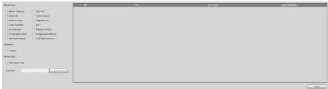
Select an alarm type. Step 2
Select Prompt, and the system prompts and records alarm information as needed. Step 3
- If you are not in the Alarm interface when alarm events you have subscribed are
triggered, there will be a displayed on the Alarm tab and the alarm
information will be recorded. Click the Alarm tab, and the sign disappears.
- If you are at the "Alarm" interface when the selected alarm is triggered, there will be detailed alarm information displayed at the right side of the interface.
Step 4 Select the check box of Play Alarm Tone, and select audio file.
System would play the audio file you have selected, when alarm events you have subscribed are triggered.

Click Remove all to remove all the alarm information.

- Click Default, and the Device is restored to default configuration.
- Click Refresh to view the latest configuration.
Configuring Camera 4.1
Configure camera's components such as lens, video and audio to ensure proper surveillance.

Functions of different devices might vary, and the actual product shall prevail.
4.1.1 Configuring Lens
4.1.1.1 Configuring Visible Image
4.1.1.1.1 Configuring Picture Parameters
You can configure the picture parameters including brightness, contrast, saturation, Chroma CNT, sharpness CNT and gamma.
Step 1 Click the Picture tab.
The Picture interface is displayed. See Figure 4-1.
The picture interface Figure 4-1

Configure picture parameters. See Table 4-1 for details. Step 2
Table 4-1 Description of picture parameters
| Parameter | Description |
| Style | Select display style of the video image, including Soft, Standard and Vivid. |
| Brightness | Changes the value to adjust the picture brightness. The bigger the value is, the brighter the picture will be. |
| Contrast | Changes the contrast of the picture. The bigger the value is, the more the contrast will be between bright and dark areas. |
| Saturation | Makes the color deeper or lighter. The bigger the value is, the deeper the color will be. Saturation value doesn't change image brightness. |
| Chroma CNT | Reduces the image color and prevents it from being too strong. The bigger the value, the better the effect. |
| Sharpness | Changes the sharpness of picture edges. The bigger the value is, the clearer the picture edges will be, and if the value is set too big, picture noises are more likely to appear. |
| Sharpness CNT | The bigger the value, the stronger the sharpness CNT. |
| Gamma | Changes the picture brightness and improves the picture dynamic range in a non-linear way. The bigger the value is, the brighter the picture will be. |
| Flip | In the Flip list, select 180° and the video image will be turned upside down. Select 0° and the video image returns to its primary condition. |
| EIS | Select the On check box to enable this function.Corrects the device shaking with difference comparison algorithm and improves the image clarity, effectively solves the picture shaking problem. |
4.1.1.1.2 Configuring Exposure
Click the Exposure tab. Step 1
The Exposure interface is displayed. See Figure 4-2.
The exposure interface Figure 4-2
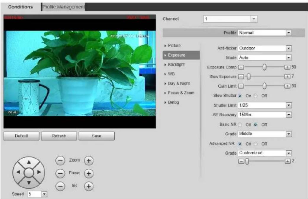
Configure exposure parameters. See Table 4-2 for details. Step 2
Parameters and its description in Table 4-2 are based on the condition that you have selected Standard as Profile.
Table 4-2 Description of exposure parameters
| Parameter | Description |
| Mode | ● Auto: Adjusts the image brightness according to the actual condition automatically.● Shutter priority: When the exposure range is normal, the system prefers the configured shutter range when auto adjusting according to the ambient lighting condition. If the image brightness is not enough and the shutter value has reached upper or lower limit, the system adjusts gain value automatically to ensure the image at ideal brightness.● Iris priority: The iris value is set to a fixed value, and the device adjusts shutter value then. If the image brightness is not enough and the shutter value has reached upper or lower limit, the system adjusts gain value automatically to ensure the image at ideal brightness.● Manual: Configure gain and shutter value manually to adjust image brightness. |
| Anti-flicker | ● 50Hz: When the current is 50Hz, the system adjusts the exposure according to ambient light automatically to ensure there is no stripe appears.● 60Hz: When the current is 60Hz, the system adjusts the exposure according to ambient light automatically to ensure there is no stripe appears.● Outdoor: You can select any exposure mode as needed. |
| Iris | SelectManualorAperture Priorityas theMode. Then you can configure the iris parameter. |
| Exposure Comp | SelectManual, Aperture PriorityorShutter Priorityas theMode. Then you can configure the exposure compensation parameter. |
| AE (Auto Exposure) Recovery | Set a recovery time. After you adjust the shutter manually, the exposure mode will be restored to the default one after the time you have set.In the selection box ofAE Recovery, you can selectOffto turn off AE recovery. |
| Shutter | SetManualorShutter Priorityas theMode. Then you can configure the parameter.Adjust the camera's shutter value. |
| 2D NR | Select theOncheck box to enable this function. Aiming at single-frame image, 2D NR averages the pixel points (points that are with image noise) with other common pixel points to decrease the image noise and achieve an acceptable and good image display effect. The higher the grade, the better the noise suppression effect. |
| 3D NR | Select theOncheck box to enable this function. Aiming at multiple-frame image, 3D NR handles information between two frames to reduce the image noise. The higher the grade, the better the noise suppression effect. |
4.1.1.1.3 Configuring Backlight
Backlight mode is divided into BLC, HLC and WDR. You can select one from the three options above at one time.
- When in BLC mode, the camera gets clearer image of the dark areas on the target when shooting against light.
- When in WDR mode, the camera constrains over bright areas and compensates dark areas to improve the image clarity.
- When in HLS mode, the camera dims strong light, and it is applicable to the exit of toll station or parking lot. This mode works well for taking pictures of human face or car plate detail under extreme low ambient light.
____ Click the Backlight tab. Step 1 The Backlight interface is displayed. See Figure 4-3.
The backlight interface Figure 4-3
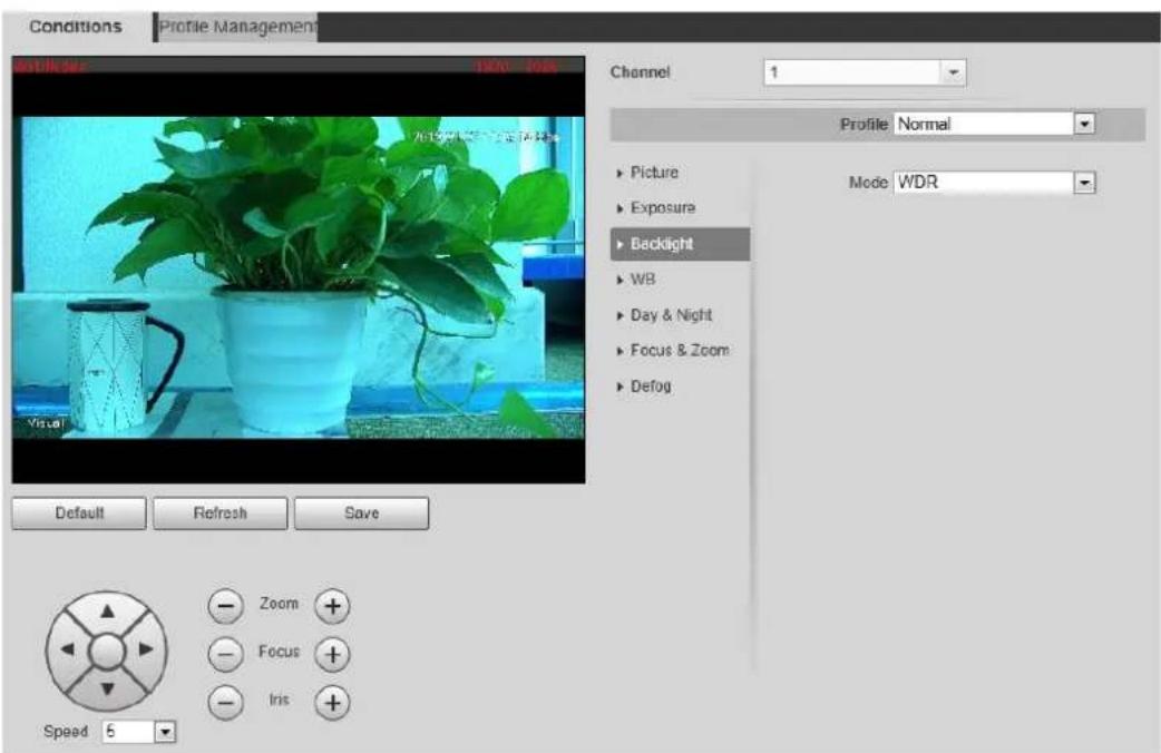
Configure backlight parameters. See Table 4-3 for details. Step 2

There might be a few seconds of video loss when the device is switching to WDR mode from other modes.
Table 4-3 Backlight mode description
| Backlight Mode | Description |
| BLC | The system adjusts exposure according to ambient lighting condition automatically to ensure the clarity of the darkest area. |
| WDR | The system dims bright areas and compensates dark areas to ensure the clarity of all the area. |
| HLS | The system constrains bright areas and reduces halo size to dim the overall brightness. |
4.1.1.1.4 Configuring White Balance
With the white balance technology, you can make a white object displaying itself clearly on the video image under all kinds of environment.
Click the WB tab. Step 1
The WB interface is displayed. See Figure 4-4.
The WB interface Figure 4-4
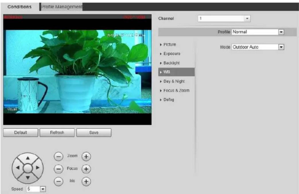
Configure white balance parameters. See Table 4-4. Step 2
Table 4-4 WB mode description
| WB Mode | Description |
| Auto | The system compensates WB according to light condition to ensure color precision. |
| Outdoor | The system auto compensates WB to most outdoor environments with natural or artificial light to ensure color precision. |
| Manual | Configure red and blue gain manually; the system auto compensates WB according to color temperature. |
| Natural | The system auto compensates WB to environments without artificial light to ensure color precision. |
| Street Lamp | The camera will implement white balance to ensure precision and clarity of the video image. |
4.1.1.1.5 Configuring Day & Night
You can configure this function to accomplish the switch of image display between color mode and black/white mode.
____ Click the Day & Night tab. Step 1
The Day & Night interface is displayed. See Figure 4-5.
The day & night interface Figure 4-5
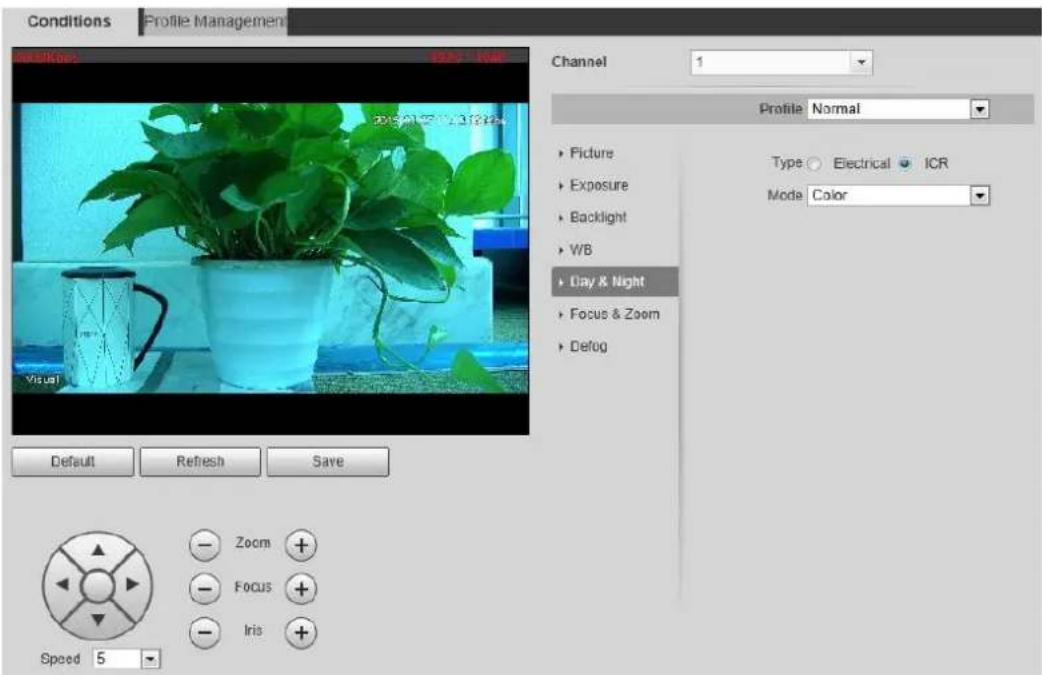
____ Configure day & night parameters. See Table 4-5. Step 2
Table 4-5 Day & night mode description
| Parameter | Description |
| Type | Select Type from Electrical and ICR. |
| Mode | You can select device display mode from Color, Auto and B/W.Day & night configuration is independent from profile management configuration.Color: The system displays color image.Auto: The system switches between color and black-and-white display according to the actual condition.B/W: The system displays black-and-white image. |
| Sensitivity | Select Auto as the Mode. Then You can configure this parameter.You can configure camera sensitivity in switching between color and black-and-white mode. |
4.1.1.1.6 Configuring Focus & Zoom
____ Click the Focus & Zoom tab. Step 1 The Focus & Zoom interface is displayed. See Figure 4-6.
The focus & zoom interface Figure 4-6
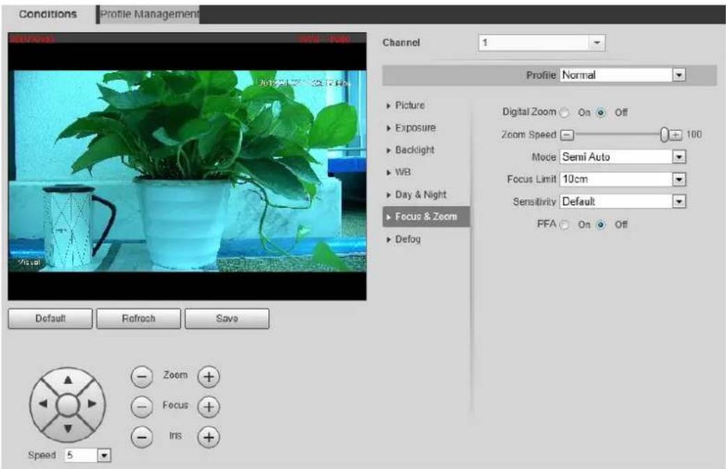
Configure the focus & zoom parameters. See Table 4-6 for details. Step 2
Table 4-6 Description of focus & zoom parameters
| Parameter | Description |
| Digital Zoom | Select theOncheck box to enable it.You can use the digital zoom to continue the zooming operation even if the optical zoom is at the maximum value. |
| Zoom Speed | The larger the value, the faster the zooming operation. |
| Mode | The camera's focusing mode.Auto: Once there is any movement or change of an object on the video image and the image turns blurry, the camera will focus again automatically.Semi Auto: A user needs to prepare some conditions for the camera to focus automatically. This is called “Semi Auto.” Pressing the focusing button, implementing the zooming operation, enabling preset or three-dimensional positioning, and PTZ’s rotation will all make the camera focus again automatically.Manual: You need to clickoron the camera’s web to achieve the focusing operation. |
| Focus Limit | The camera’s minimum focusing distance. If the focusing distance is too small, it might get the camera focus on its dome. |
| Sensitivity | Select fromHigh,DefaultandLow.When you selectHigh, it will be easier for the camera to focus. |
| PFA | Select the check box ofOnto enable the infrared correction.Then when you implement the zooming or focusing operation under low lighting condition, the camera will turn on the infrared light to aid you. |
| Lens Init | ClickLens Initto initialize the lens. The system will clear the zooming and focusing data you have set. |
4.1.1.1.7 Configuring Defog
The image quality will be compromised in foggy or hazy environment, and defog can be used then to improve image clarity.
Click the Defog tab. Step 1
The Defog interface is displayed. See Figure 4-7.
The defog interface Figure 4-7

Configure the defogging settings. See Table 4-7. Step 2
Table 4-7 Defogging settings description
| Defogging Settings | Description |
| Auto | The system adjusts image clarity according to the actual condition. |
| Manual | Adjust image clarity manually. |
| Off | Defogging function disabled. |
4.1.1.1.8 Restoring Lens to the Default Settings
After you have modified lens parameters as mentioned above in 4.1.1.1, if you find situations such as unclear images and abnormal colors, you can restore those parameters to the default settings—you just need to click the Default button and click Save to finish configuration. See Figure 4-8.
Restoring lens to the default settings Figure 4-8

4.1.1.2 Configuring Thermal Image

To find and configure thermal image, you need to select Setting> Camera > Conditions > Conditions first, and in the Channel box, select 2. See the following steps for details.
Configure a specific scenario where you use the camera, including indoor scenario, outdoor scenario, and adaptive scenario. You can choose a scenario you need, and configure and check the scenario.
Step 1 Select Setting> Camera > Conditions > Conditions.
The Conditions interface is displayed.
In the Channel box, select 2. Step 2
The thermal image interface is displayed. See Figure 4-9.

The thermal image interface might vary with different cameras, and the actual product shall prevail.
The thermal image interface Figure 4-9
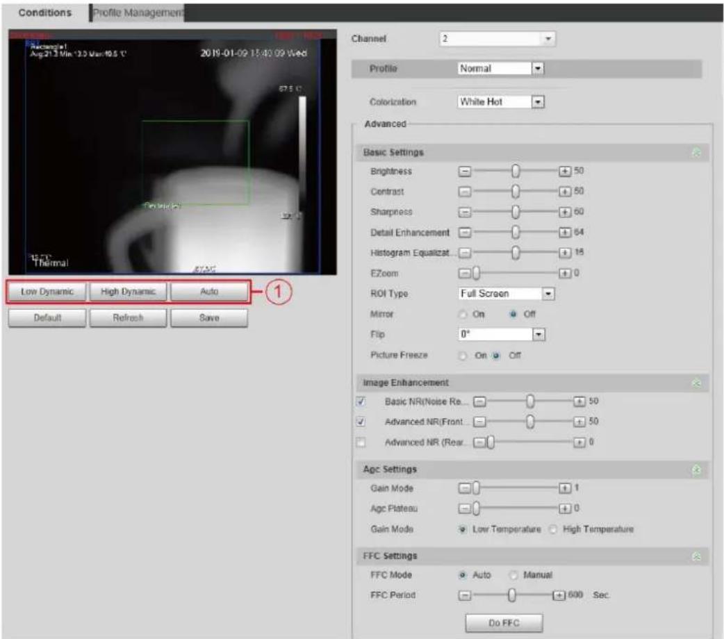
Step 3 Configure lens parameters. For detailed description, see Table 4-8.
Table 4-8 Parameter description of lens
| Classification | Parameter | Description |
| Profile | Profile | Common model, day and night can be selected.You can set the relevant parameter of thermal image after you configure files. |
| Scene (marked by 1 in Figure 4-9) | Select the duplicate frame and set the frequently used video parameter as the user-defined scene. Or, you can select the default scene and set the display of the thermal image.Low Dynamic: Thermal images will be displayed based on the configuration of low dynamic scene.High Dynamic: Thermal images will be displayed based on the configuration of high dynamic scene.Auto: Thermal images will be displayed based on the configuration of auto scene. | |
| Basic Settings | Colorization | Add color to the thermal imagery image and use color to indicate the temperature. "White glow" is the default color. White glow: Lighter when the temperature is higher in gray image. Black glow: Lighter when the temperature is lower in gray image. Fusion: Color is concentrated on the range of purple-red-yellow. More purple when the temperature is lower and more yellow when the temperature is higher. Rainbow: Color is concentrated on the range of blue-green-red-yellow. Bluer when the temperature is lower and more yellow when the temperature is higher. Golden autumn: Color is concentrated on the range of red- yellow. Redder when the temperature is lower and more yellow when the temperature is higher. Midday: Color is concentrated on the range of blue-green-red-yellow. Bluer when the temperature is lower and more yellow when the temperature is higher. Iron oxide red: Its color range is similar to that of Midday, but its brightness is lower than Midday. Amber: It's mainly represented as brown. Brighter when the temperature is higher. Boulder: Color is concentrated on the range of purple - red- yellow-green- blue. More purple when the temperature is lower and bluer when the temperature is higher. The setting sun: Color is concentrated on the range of blue- red- yellow. Bluer when the temperature is lower and more yellow when the temperature is higher. Ice and fire: In color image, high temperature objects show red and low temperature objects show blue. Ice and fire is usually used to give a warning. Oil painting: Color is concentrated on the range of purple-blue-green- yellow-red. More purple when the temperature is lower and redder when the temperature is higher. Pomegranate: It's mainly represented as wine red. Brighter when the temperature is higher. Green jade: It's mainly represented as aquamarine. Brighter when the temperature is higher. |
| Brightness | Change the overall image brightness through linear mode. The bigger the value is, the brighter the image will be, and the smaller the darker. | |
| Sharpness | Change the sharpness of image edges. The larger the value, the more obvious the image edge.Do not make the value too large to prevent image noise. | |
| EZoom | Enlarge the thermal image according to the zoom time you have set. | |
| ROI Type | Select the district of strengthening video quality. The brightness and clarity of the chosen district will be higher. District consists of 25% central point, 50% central point, 75% central point, full screen, bottom part, middle part, above part and user-defined part.When you setROI Type to Custom, you need to press and drag the left mouse button. Then, add the "ROI Type" box. | |
| Mirror | Open the mirror image and the monitor image will reverse from left to right. | |
| Picture Freeze | When you are using the preset, the preset image that has been used will be directly represented. The image during the movement of PTZ will not be displayed. | |
| Basic NR (Noise Reduction) | Average the pixel of single frame image with other pixels to reduce the image noise.Select the copy frame, open the basic noise reduction and configure the class of basic noise reduction. The higher the class, the better the noise reduction, but the image will be less clear. | |
| Gain settings | Auto Gain | The larger the gain value, the more unstable the image. |
| Balanced Gain | The larger the district, the bigger the contrast. | |
| Gain Model | Low-temperature mode and high-temperature mode are contained. | |
| FFC Settings | FFC Mode | Method of correcting the shutter.• Auto: According to the switch period that you have configured, the shutter will be corrected regularly.• Manual: Correct the shutter by yourself. |
| FFC Period | You can configure this parameter only when FFC Mode is set to beAuto.Adjust time gap of correcting the shutter automatically. | |
| Do FFC | Click Do FFC to trigger the shutter correcting for this time. |
Click Save to finish configuration. Step 4

Click Reset and the lens properties are restored to the primary state.
4.1.1.3 Configuring Profile Management
When configuring the profile management, you can select from Normal, Full Time and Schedule based on your own needs.
Step 1 Select Setting > Camera > Conditions > Conditions > Profile Management.
The Profile Management interface is displayed.
____ Profile management configuration: Step 2
- When Profile Management is set as Normal, the surveillance system works under normal configuration.
Common setting Figure 4-10

- When Profile Management is set as Full Time, you can select Day or Night as Always Enable, and the surveillance system works under Always Enable.
Full time setting Figure 4-11

- When Profile Management is set as Schedule, you can drag the slide block to set certain time as Day or Night. For example, set 8:00–5:00 PM as day, and 0:00–8:00 and 18:00–24:00 as night. System works under corresponding configuration in different time.
Switching based on time Figure 4-12

Click Save to finish configuration. Step 3
4.1.2 Configuring Video Parameters
4.1.2.1 Configuring Video Streaming
Configure video stream parameters, including stream type, encode mode, resolution, frame rate, bit stream control, bit stream, I frame interval, SVC, and watermark.
Select Setting > Camera > Video > Video. Step 1
The Video interface is displayed. See Figure 4-13.

The default bit stream value of different devices might vary, and the actual product shall prevail.
Video Figure 4-13

Configure video streaming. For detailed description, see Table 4-9. Step 2
Table 4-9 Parameter description
| Parameter | Description |
| Enable | Select the option box to enable sub stream (enabled by default).Enabling sub stream 1 and sub stream 2 at the same time are supported. |
| Encode Mode | Encode mode of video.H.264: Main profile encode mode.H.264H: High profile encode mode.H.264B: Baseline profile encode mode.MJPEG: Under this mode, the higher streaming value is required to ensure the clarity of images. And, we suggest that you should use the maximum streaming value we have offered. |
| Resolution | The resolution of the video The max resolution of different devices might vary, and the actual product shall prevail. |
| Frame Rate (FPS) | The number of frame in one second of video The higher the FPS is, the clearer and smoother the video will be. |
| Bit rate | You can select bit rate type:Fixed: the bit rate changes little and keeps close to the set bit rate value.Changeable: the bit rate changes as monitoring scene changes.Bit rate type can only be set as Fixed when Encode Mode is set as MJPEG. |
| Image quality | This parameter can be configured only when the bit rate type is set as "Changeable."Image quality can be classified as the six levels of "the best", "the better", "good", "bad", "the worse", "the worst." |
| Reference bit rate value | According to resolution and frame rate you have set, we have offered you a reference bit rate value, which is also the best value you can adopt. |
| Bit rate | This parameter can be configured only when the bit rate type is set as Fixed.If you select the bit rate value according to “reference bit rate value”, the streaming changes little and keeps close to the bit rate value you have selected.Select Customized and you can configure bit rate value manually. |
| Maximum bit rate | This parameter can be configured only when bit rate type is set as Changeable.You can select the max value of the bit rate according to the reference bit rate value, and the bit rate changes with monitoring scenes, but the max bit rate keeps close to the value you set. |
| I Frame Interval | The number of P frame between two I frames, and the I Frame Interval range changes as FPS.It is recommended to set I Frame Interval twice as big as FPS. |
| SVC | Scaled video coding, able to encode a high quality video bit stream that contains one or more subset bit streams. The default value is 1, which means no layered coding. |
| Watermark Settings | Select the check box to enable watermark.Then you can check if the video has been tampered by verifying the watermark. |
| Watermark character | The default character is Digital CCTV.You can configure at most 128 watermark characters which are composed of number, letter, underline and dash. |
Click Save to finish configuration. Step 3
4.1.2.2 Configuring Image Streaming
Configure parameters of image streaming which cover snapshot type/interval, image size/quality.
Select Setting > Camera > Video > Snapshot. Step 1
The Snapshot interface is displayed. See Figure 4-14.
Snapshot Figure 4-14

Configure snapshot streaming. See Table 4-10. Step 2
Table 4-10 Parameter description
| Parameter | Description |
| Snapshot type | You can select General or Event.General means the system takes snapshot as scheduledEvent means snapshot functions when video\audio detection, event or alarm is triggered. |
| Image Size | The same resolution with main stream. |
| Quality | Snapshot quality. The bigger the value, the better the snapshot quality. |
| Snapshot interval | Snapshot frequency.Select Customized to manually configure snapshot frequency. |
| Heat map in jpeg | Select the check box and snapshots of thermal images will carry the temperature-measuring information. |
Click Save to finish configuration. Step 3
4.1.2.3 Configuring Video Overlay
Configure Overlay which covers Privacy Masking, Channel Title, Time Title, Geography location, Font, and Picture Overlay.
4.1.2.3.1 Configuring Privacy Masking
You can enable this function if you need to cover certain area in the video image.

This function is available only for bullet cameras.
Select Setting > Camera > Video > Overlay. Step 1
The Overlay interface is displayed.
Click Privacy Masking. Step 2
The Privacy Masking interface is displayed. See Figure 4-15.
Privacy masking interface Figure 4-15

Step 3 Select Enable, and then drag the block to the area that you need to cover.

- You can draw four area boxes at most.
- Click Remove All to delete all the area boxes; you can also just select one box, and click Delete or right-click to delete it.
____ Click Save to finish configuration. Step 4
4.1.2.3.2 Configuring Channel Title
You can enable this function if you need to display Channel title in the video image.
Select Setting > Camera > video > Overlay. Step 1
The Overlay interface is displayed.
Click Channel Title. Step 2
The Channel Title interface is displayed. See Figure 4-16.
Channel title Figure 4-16
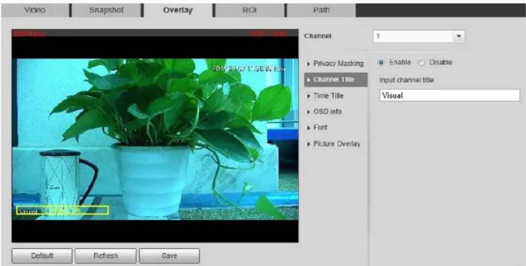
Step 3 Select Enable and enter channel title, and then the title displays in the video image.

You can drag the "Channel Title" box in the video image with your mouse to adjust the box's location.
Click Save to finish configuration. Step 4
4.1.2.3.3 Configuring Time Title
You can enable this function if you need to display time on the video image.
Select Setting > Camera > Video > Overlay. Step 1
The Overlay interface is displayed.
Click Time Title. Step 2
The Time Title interface is displayed. See Figure 4-17.
Time title Figure 4-17

Step 3 Select the Enable check box, and the time displays in the video image.
Step 4 Click Week Display, and then the week information displays in the video image.

You can drag the "Time Title" box in the video image with your mouse to adjust the box's location.
Click Save to finish configuration. Step 5
4.1.2.3.4 Configuring OSD Info
Enable this function if you want to display words on the video image.

- Text Overlay and Picture Overlay can't work at the same time.
- This function is available on select models and the actual interface shall prevail.
Select Setting > Camera > Video > Overlay. Step 1
The Overlay interface is displayed.
Click OSD Info. Step 2
The OSD Info interface is displayed. See Figure 4-18.
OSD Info Figure 4-18

Step 3 Select the Enable check box of Text Overlay, and enter text based on your own needs.
Then, select the text align method, and the OSD Info box is displayed on the video image.

You can drag the OSD Info box on the video image with your mouse to adjust the box's location.
____ Click Save to finish configuration. Step 4
4.1.2.3.5 Configuring Font
You can adjust size and color of the font in the video images based on your own needs.
Select Setting > Camera > video > Overlay. Step 1
The Overlay interface is displayed.
Click the Font tab. Step 2
The Font interface is displayed. See Figure 4-19.
Font setting Figure 4-19

Step 3 Select color and size of the font based on your own needs.
Click Save to finish configuration. Step 4
4.1.2.3.6 Configuring Picture Overlay
You can enable this function if you need to display picture information in the video image.

Geography location and Picture overlay can't work at the same time.
Select Setting > Camera > video > Overlay. Step 1
The Overlay interface is displayed.
Click the Picture Overlay tab. Step 2
The Picture Overlay interface is displayed. See Figure 4-20.
Picture overlay interface Figure 4-20

Select the Enable check box. Step 3
You will be informed that OSD information is to be closed. Click Save.
Step 4 Click Upload Picture, and select a picture. The picture is displayed in video images.

You can drag the "Picture Overlay" box in the video image with your mouse to adjust the box's location.
Click Save to finish configuration. Step 5
4.1.2.4 Configuring ROI
Select ROI in the image, and then the selected image would display with configured quality.
Select Setting > Camera > Video > ROI. Step 1
The ROI interface is displayed. See Figure 4-21.
ROI interface Figure 4-21

Select the Enable check box. Step 2
Step 3 Hold the left mouse button to draw a ROI area on video images. You can also configure the ROI's display quality.

- You can draw at most four ROI areas.
- Click Remove All to delete all the area boxes; you can also just select one box, and click Delete or right-click to delete it.
Click Save to finish configuration. Step 4
4.1.2.5 Configuring Storage Path
Configure storage paths covering Live Snapshot, Live Record, Playback Snapshot, Playback Download, Video Clips, and Heat Map.
Select Setting > Camera > Video > Path. Step 1
The Path interface is displayed. See Figure 4-22.
Storage path interface Figure 4-22

Step 2 Click Browse, and configure storage paths of live snapshot, live record, playback snapshot, playback download, video clips, and heat map. See Table 4-11 for detailed description.
Table 4-11 Storage path description
| Path | Description |
| Live Snapshot | Live snapshot refers to the snapshot of live interface.C:\Users\admin\WebDownload\LiveSnapshot is the default path. |
| Live Record | Live record refers to the recorded video of live interface.C:\Users\admin\WebDownload\LiveSnapshot is the default path. |
| Playback Snapshot | Playback snapshot refers to the snapshot of playback interface.C:\Users\admin\WebDownload\LiveSnapshot is the default path. |
| Playback Download | Playback download refers to the downloaded video of playback interface.C:\Users\admin\WebDownload\LiveSnapshot is the default path. |
| Video Clips | Video clips refer to the clipped video of playback interface.C:\Users\admin\WebDownload\LiveSnapshot is the default path. |
| Heat Map | Heat map comes from the location Setting > Temperature.C:\Users\admin\WebDownload\LiveSnapshot is the default path. |

Administrator in the default path is the user account.
Click Save to finish configuration. Step 3
4.1.3 Configuring Audio Parameters
Configure audio parameters covering Encode Mode, Sampling Frequency, Audio in Type, and Noise Filter.

Functions of different devices might vary and the actual product shall prevail.
Step 1 Select Setting > Camera > Audio.
The Audio interface is displayed. See Figure 4-23.
Audio Figure 4-23

Step 2 Configure Audio parameters. For detailed description, see Table 4-12.
Table 4-12 Parameters
| Parameters | Description |
| Enable | Audio can be enabled only when video is enabled. Enable Main Stream or Sub Stream, and the network stream is composed of both audio and video streams. If you do not select Main Stream or Sub Stream, then only video images are transmitted. |
| Encode Mode | You can select audio encode mode. G.711A, G.711Mu, and AAC are included.The configured audio encode mode applies to audio and intercom. |
| Sampling Frequency | Audio's sampling frequency. 8K and 16K are included. |
| Audio in Type | Two audio types are selectable.Linein: External audio input source is required.Mic: External audio input source is not required. |
| Noise Filter | Enable this function, and the system auto filters ambient Noise. |
| Microphone Volume | Adjusts microphone volume.This function is not available for all devices. |
| Speaker Volume | Adjusts speaker volume. |
| This function is not available for all devices. |
Click Save to finish configuration. Step 3
Configuring Network 4.2
4.2.1 Configuring TCP/IP
You need to configure the camera's IP address and DNS server to connect the camera with other devices in the network.
Preparation
You have connected the camera to network.
Procedure
Step 1 Select Setting > Network > TCP/IP.
The TCP/IP interface is displayed. See Figure 4-24.
TCP/IP interface Figure 4-24

Configure TCP/IP parameters. See Table 4-13 for details. Step 2
Table 4-13 TCP/IP parameters
| Parameter | Description | |
| Host Name | Enter host name, 15 characters at most. | |
| Ethernet Card | Wire (Default) is set by default. | |
| Mode | Static: You need to manually configure IP Address, Subnet Mask and Default Gateway.DHCP: Obtains IP address automatically. With DHCP enabled, IP Address, Subnet Mask and Default Gateway cannot be configured. You can check the current IP address whether the DHCP takes effect or not. | |
| MAC Address | Host's MAC address, cannot be modified. | |
| IP Version | Select IPv4 or IPv6. | |
| IP Address | You can type IP address and subnet mask according to your own needs.All the IPv6 addresses will be validated, so ensure IP address and subnet mask are in the same network segment, which means the front parts of the IP address and the default gateway are the same one. | |
| Subnet Mask | ||
| Default Gateway | Configure as needed, the default gateway must be in the same network segment with the IP address. | There is no default gateway for IPv6.Enter 128 digits in preferred DNS and alternate DNS. |
| Preferred DNS | IP address of the preferred DNS. | |
| Alternate DNS | IP address of the alternate DNS. | |
| Enable ARP/Ping to set IP address service. | Select the check box, get the device MAC address, and then you can modify and configure the device IP address with ARP/ping command.This is enabled by default. During reboot, you will have no more than two minutes to configure the device IP address with a ping packet which has certain length. The server will be turned off in 2 minutes, or it will be turned off immediately after IP address configuration. If this is not enabled, the IP address cannot be configured with ping packet.A demonstration of configuring IP address with ARP/Ping.1. To obtain a free IP address, you need to ensure that the Device and your PC are in the same LAN.2. Get MAC address from the device label.3. Open command editor on your PC and enter the following command.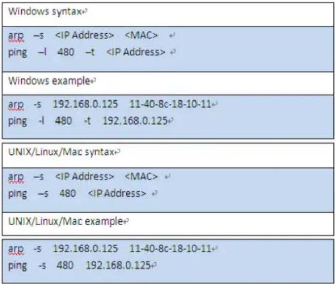 4. Reboot through power or network.5. Check your PC command line. If there is information such as "Reply from 192.168.0.125...", you have done configuration successfully. Turn it off then.6. Enter http://(IP address) in the browser address bar to log in. 4. Reboot through power or network.5. Check your PC command line. If there is information such as "Reply from 192.168.0.125...", you have done configuration successfully. Turn it off then.6. Enter http://(IP address) in the browser address bar to log in. | |
Click Save to finish configuration. Step 3
4.2.2 Configuring Port
4.2.2.1 Configuring Port Parameters
You can configure the maximum port number and each port value.
Step 1 Select Setting > Network > Port > Port.
The Port interface is displayed. See Figure 4-25.
Port Figure 4-25

Configure parameters. See Table 4-14 for details. Step 2

- Configuration of Max Connection takes effect immediately and others after reboot.
- 0–1024, 37780, 37880, 1900, 3800, 5000, 5050, 9999, 37776, 39999 and 42323 are occupied for specific uses.
- It is not recommended to use the default value of other port during port configuration.
Table 4-14 Port parameter description
| Parameters | Description |
| Max Connection | The maximum number of users (web client, platform client or mobile phone client) that can connect to the device simultaneously, the value is 10 by default. |
| TCP Port | Port of transmission control protocol. The value is 37777 by default. |
| UDP Port | User datagram protocol port, the value is 37778 by default. |
| HTTP Port | HTTP communication port. The default value is 80. If you have modified the default value, when logging in through a browser, you need to add the latest port number to the end of IP address. |
| RTSP Port | 554 is the default port number. If you play live view through Apple's QuickTime or VLC, the following format is available. This function is also available for Blackberry.When the URL format requiring RTSP, you need to specify channel number and bit stream type in the URL, and also user name and password if needed.When playing live view with Blackberry smart phone, you need to turn off the audio, and then set the code mode to H.264B and resolution to CIF.URL format example:rtsp://username:password@ip:port/cam/realmonitor?channel=1&subtype=0Username: admin, for example.passwordIP: your device IP.Port: leave it if the value is 554 by default.Channel 1: Channel number, starts from 1. For example, if you are using channel 2, then the channel=2.Subtype refers to Bit stream type; 0 means main stream (Subtype=0) and 1 means sub stream (Subtype=1).So, if you require the sub stream of channel 2 from a certain device, then the URL should be:rtsp://admin:admin@10.12.4.84:554/cam/realmonitor?channel=2&subtype=1If user name and password are not needed, then the URL can be:rtsp://ip:port/cam/realmonitor?channel=1&subtype=0 |
| Enable HTTPS | HTTPS: Control of communication service. After selecting the check box, you can log in the Device through https://ip:port. When there is a default port, you can log in through https://ip. |
| HTTPS Port | HTTPS communication port whose value can be selected from 1025-65534 and 443 is the default value. |
Click Save to finish configuration. Step 3
4.2.2.2 Configuring ONVIF Verification When Logging
With ONVIF port standard, network video products (video recording device and other recording devices included) of different manufacturers can be connected to each other.

- ONVIF is enabled by default.
- When logging in through ONVIF, the default names of both "username" and "password" are admin and the default port value is 80.
Select Setting > Network > Port > ONVIF. Step 1
The ONVIF interface is displayed. See Figure 4-26.
ONVIF Figure 4-26

Step 2 Select the On check box in Authentication bar
Click Save to finish configuration. Step 3
4.2.3 Configuring PPPoE
Point-to-Point Protocol over Ethernet, it is one of the protocols that device uses to connect to the internet. Get the PPPoE user name and password from the Internet Service Provider, and then, set up network connection through PPPoE, the device will acquire a WAN dynamic IP address.

- Disable UPnP while using PPPoE to avoid possible influence.
- After making PPPoE connection, the device IP address can not be modified through web interface.
Select Setting > Network > PPPoE. Step 1
The PPPoE interface is displayed. See Figure 4-27.
PPPoE Figure 4-27
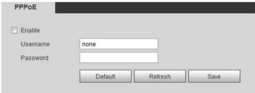
____ Select the Enable check box, and type user name and password. Step 2
Click Save to finish configuration. Step 3
The successful prompt displays, and then the real-time WAN IP address is displayed.
You can visit device through this IP address.
4.2.4 Configuring DDNS
When device's IP address is frequently changed, you can enable DDNS to dynamically update the relation between domain name and IP address (both of which are in the DNS server). By this, you can log in the device through a domain name.
Preparation
Before making any changes, check if your device supports the DNS server.
- If Quick DDNS is the DDNS' type, you do not need to register a new domain name.
- If Quick DDNS is not the DDNS' type, you need to log in the domain name of website registration provided by DDNS service provider.

Register and log in the DDNS website, and then you can view the information of all the connected devices in your account.
Procedure
Select Setting > Network > DDNS. Step 1
The DDNS interface is displayed. See Figure 4-28.
DDNS setting interface Figure 4-28
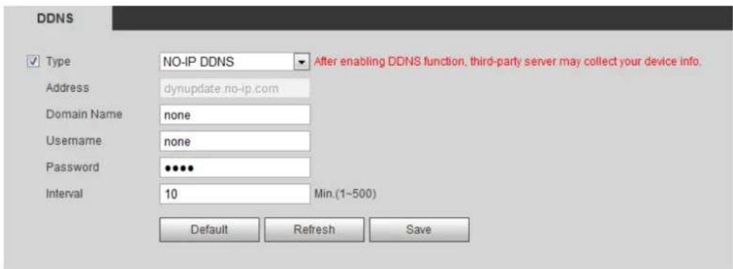
Select Type and configure as needed. Step 2
Table 4-15 DDNS parameters
| Parameter | Description |
| Type | See the name and web site of DDNS service provides below:• "members.dyndns.org" is the IP address of Dyndns DDNS.• "dynupdate.no-ip.com" is the IP address of NO-IP DDNS.• "members.3322.org" is the IP address of CN99 DDNS. |
| Address | |
| Domain name | The domain name you registered on the DDNS website. |
| User name | Enter the user name and password you got from DDNS service provide.You need to register an account (with user name and password) on the DDNS service provides' website. |
| Password | |
| Update period | The update cycle of the connection between your device and the server. 10 minutes are set by default. |
Click Save to finish configuration. Step 3
Open your browser, and type the domain name into address bar. Press Enter. If a web interface is displayed, the configuration is finished successfully.
4.2.5 Configuring SMTP
Configure SMTP (Email). When alarm, video detection, abnormal event and intelligent are triggered, SMTP alarms will be transmitted to the specific Emails you have configured.
Select Setting > Network > SMTP (Email). Step 1
The SMTP (Email) interface is displayed. See Figure 4-29.
SMTP (Email) Figure 4-29

Configure your SMTP server. Step 2
Step 3 For SMTP (Email)'s other parameters to be configured, see Table 4-16.
Table 4-16 SMTP (Email) parameter description
| Parameters | Description |
| Anonymity | Enable Anonymity, and senders' identities will not be displayed in Emails transmitted to others. |
| Sender | Sender's email address |
| Encryption type | Select Authentication type from None, SSL and TLS. TLS is set by default. |
| Attachment | Select the check box to support attachment in the email. |
| Title | You can enter no more than 63 characters in Chinese, English, and Arabic numerals. |
| Receiver | Receiver's mail address. Supports 3 addresses at most. |
| Interval | Time intervals of sending alarm Emails. "0" means there is no interval. Set a time interval (normally >0s) as you want and when alarm, video detection, or event is triggered, Emails will not be transmitted all the time but be transmitted in the time interval you have set. This function is aimed at easing the pressure that is put on the Email server when there are quite a lot of abnormal events. |
| Health Mail | The system sends test mail to check if the connection is successfully set up. Select Health Mail to configure Update Period. E-mail testing results will be transmitted in time intervals you have set. |
| Test | Test the email sending and receiving function. If the configuration is correct, you would receive test email. Save email configuration before running rest. |
____ Click Save to finish configuration. Step 4
4.2.6 Configuring UPnP
Configure UPnP protocols to establish the reflection relation between intranet and external network. A user can access IP address of external network to visit devices in the intranet.
Preparation
- Ensure UPnP network service has been installed to your PC.
- Log in the router, and configure WAN IP address to set up internet connection.
- Enable UPnP in the router.
- Connect your device to the LAN port of the router.
- Set IP address of your router as that of your device, or select DHCP to obtain IP address automatically.
Procedure
Step 1 Select Setting > Network > UPnP.
The UPnP interface is displayed. See Figure 4-30.
UPnP Figure 4-30

Select the Enable check box. Step 2
Select mode, and service name in the port mapping list. Step 3
UPnP can be classified as custom mode and default mode.
- Under custom mode, you can change external ports.
- Under default mode, you do not need to change ports and reflection relations.
Click Save to finish configuration. Step 4
Type "http:// (external network IP address): (external port number)" to access devices in Intranet whose ports correspond to your router.
4.2.7 Configuring SNMP
SNMP (Simple Network Management Protocol) is a basic network management framework. You need to install certain software to the Device to obtain the Device's information.
Preparation
- Install SNMP monitoring and managing tools such as MIB Builder and MG-SOFT MIB Browser.
- You can contact technical support for the MIB file that matches the current version.
Procedure
Select Setting > Network > SNMP. Step 1
The SNMP interface is displayed. See Figure 4-31 and Figure 4-32.
Figure 4-31 SNMP (1)

SNMP (2) Figure 4-32

Select the Version check box to enable SNMP. Step 2
Configure SNMP parameters. See Table 4-17 for details. Step 3
In the Trap Address bar, enter the IP address of the PC that has MIB Builder and MG-SOFT MIB Browser installed, other parameters leave to the default.
Table 4-17 SNMP parameter description
| Parameter | Description |
| SNMP Version | Select a version and its information will be displayed in the SNMP interface.Select v1, and only v1's information is displayed.Select v2, and only v2's information is displayed.Select v3, and you can configure user name, password and authentication type. It requires corresponding user name, password and authentication type from the server to visit your device. V1 and v2 version are now unavailable. |
| SNMP Port | Refers to the listening port of the software agent in the device. |
| Community | A character string, acts as a clear text password which can manage network's process and agent process. It defines the relation concerning certification, access, and escrow between agent and administrator. Device and agent must be consistent. |
| Read community, write community | Refers to the read and write community string that the software agent supports.[cyyo]You can enter number, letter, underline and dash to form the name. |
| Trap | SNMP trap is a SNMP agent which transmits information such as important event or change of state to the administrator. |
| Trap address | A destination address to which agent program sends trap information. |
| Trap Port | A destination port to which agent program sends trap information. 162 set by default and range from 1–65535. |
| Read-only username | The name is "public" by default. You can enter number, letter, underline to form the name. You can enter number, letter, underline to form the name. |
| Read/Write username | The name is "private" by default. You can enter number, letter, underline to form the name. You can enter number, letter, underline to form the name. |
| Authentication type | You can select from MD5 and SHA, the default type is MD5. |
| Authentication password | It should be no less than 8 digits. |
| Encryption type | The default is CBC-DES. |
| Encryption Password | It should be no less than 8 digits. |
Click Save to finish configuration. Step 4
View device information. Step 5
1) Run MIB Builder and MG-SOFT MIB Browser.
2) Compile the two MIB files with MIB Builder.
3) Load the generated modules with MG-SOFT MIB Browser.
4) Enter the IP address of the device you need to manage in the MG-SOFT MIB Browser, and then select version to search.
5) Unfold all the tree lists displayed in the MG-SOFT MIB Browser, and then you can view the configuration information, video channel amount, audio channel amount and software version.

Use PC with Windows OS and disable SNMP Trap service. The MG-SOFT MIB Browser will display prompt when alarm is triggered.
4.2.8 Configuring Bonjour
Bonjour is also called zero-configuration networking. With Bonjour built into devices such as your phone, this thermal camera can be searched and accessed. Bonjour is a protocol of industry standard which allows devices search and find each other. IP address or DNS server is not required during this process.
Enable Bonjour in this thermal camera, and this camera will be automatically detected by your client-side or web with Bonjour function. When this thermal camera is detected by Bonjour, server name you have set will be displayed.

Bonjour is enabled by default.
Select Setting > Network > Bonjour. Step 1 The Bonjour interface is displayed. See Figure 4-33.
Bonjour Figure 4-33

Select the Enable check box, and then configure server name. Step 2
Click Save to finish configuration. Step 3
You can use Safari browser, and your client side or web with Bonjour function to access the thermal camera's web.
Click "Show All Bookmarks" in Safari. Step 1
____ Enable Bonjour, and then, in your LAN, all the network cameras in which the "Bonjour" Step 2 is enabled are displayed.
____ Click to visit the corresponding Web interface. Step 3
4.2.9 Configuring Multicast
The Device has limit towards web visitors. If several people access this Device's web in the meantime, video images may not be represented. To solve the problem, you can set up the Device's multicast IP and adopt multicast protocol.
Step 1 Select Setting > Network > Multicast.
The Multicast interface is displayed. See Figure 4-34.
Multicast Figure 4-34

Step 2 Select Enable and then enter IP address and port number. For detailed description, see Table 4-18.
Table 4-18 Multicast
| Parameter | Meaning |
| Description | The Multicast IP address of Main Stream/Sub Stream is 224.1.2.4 by default, and the range is 224.0.0.0–239.255.255.255. |
| Port | See the multicast port of corresponding stream: Main Stream: 40000; Sub Stream1: 40016; Sub Stream2: 40032, all the range is 1025–65500. |
____ Click Save, and the login interface is displayed. The configuration finishes. Step 3 In the Live interface, set Protocol to Multicast, and then you can view the video image with Multicast protocol.
4.2.10 Configuring Auto Registration
In the Auto Register interface, you can set up an IP address to which the camera will report its location.
Step 1 Select Setting > Network > Auto Register.
The Auto Register interface is displayed. See Figure 4-35.
Auto registration Figure 4-35

Select the Enable check box. Step 2
Set up auto registration parameters. See Table 4-19. Step 3
Table 4-19 Auto registration parameter description
| Parameter | Description |
| IP Address | IP address or domain name to which the camera transmits its location. |
| Port | The port for auto registration. |
| Sub-device ID | Your device ID given by the server. |
____ Click Save to finish configuration. Step 4
4.2.11 Configuring 802.1X
802.1X can control the Device's access to LAN.
Select Setting > Network > 802.1x. Step 1
The 802.1x interface is displayed. See Figure 4-36.
802.1x Figure 4-36

Select the Enable check box. Step 2
Set up 802.1x parameters. See Table 4-20. Step 3
Table 4-20 Parameters of 802.1x
| Parameter | Description |
| Authentication | PEAP (protected EAP protocol). |
| Username | The user name that was authenticated on the server. |
| Password | Password of your username. |
Click Save to finish configuration. Step 4
4.2.12 Configuring QoS
QoS can solve problems including network delay and congestion. It helps to assure bandwidth, reduce transmission delay, packet loss rate and delay jitter to improve service quality.
For DSCP (Differentiated Services Code Point), there are 64 priority degrees (0-63) of data packets. 0 represents the lowest and 63 the highest. Based on those differences, the 64 priority degrees will be classified as different groups. Each group occupies different bandwidth and will be abandoned accordingly. The entire configuration is to improve video quality.
Select Setting > Network > QoS. Step 1
The QoS interface is displayed. See Figure 4-37.
QoS Figure 4-37

Set up QoS parameters. See Table 4-21 for details. Step 2
Table 4-21 QoS parameter description
| Parameters | Description |
| Real-time Monitor | Priority of the data packets that are used for network surveillance. |
| Command | Priority degree used for the Device's configuration and check which do not concern those surveillance data bags. |
Click Save to finish configuration. Step 3
Peripheral 4.3
Manage the Camera's components.
4.3.1 Configuring IR Light
Step 1 Select Setting > Peripheral > IR Light.
The IR Light interface is displayed. See Figure 4-38.
IR light Figure 4-38

Configure IR light's running mode. Step 2
- Zoom Prio: When the camera zooms in or out the visible surveillance image, the IR light's brightness will be adjusted automatically.
- Manual: Adjust the IR light's brightness manually to realize the best image display effect under night vision condition.
Click Save to finish configuration. Step 3
4.3.2 Configuring Wiper
Step 1 Select Setting > Peripheral > Wiper.
The Wiper interface is displayed. See Figure 4-39.
Wiper Figure 4-39

Configure IR light's running mode. Step 2
- Timing: You can configure the Interval Time and Period.
- Interval Time: Interval from the point when the wiper starts to the point when the wiper stops.
- Period: Time when the wiper works.
- Click Save to finish configuration.
• Manual: Turn on and off the wiper manually.
- Interval Time: Interval from the point when the wiper starts to the point when the wiper stops.
- Click Start to get the wiper work in the interval time you have just set, and if you think the wiper has done enough work, click Stop to end it; Click Once to get the wiper work for one round.
4.3.3 Configuring Fan
Step 1 Select Setting > Peripheral > Fan.
The Fan interface is displayed. See Figure 4-40.
Fan Figure 4-40

Configure fan's running mode: Step 2
• Auto: Fan works automatically. Click Save to finish configuration.
- Manual: Start your fan manually. Select the Enable check box and click Save to finish configuration.
4.3.4 Configuring Heater
Step 1 Select Setting > Peripheral > Heater.
The Heater interface is displayed. See Figure 4-41.
Heater Figure 4-41

Configure heater's running mode: Step 2
- Auto: Select Start Tem and Stop Tem as the temperature range for heater to start, and click Save. When the sensor temperature is in the range, heater works automatically.
- Manual: When you think it's cold enough and you want to let the camera work in a warm condition, you can select Manual as the Mode. Select the On check box, and click Save to finish configuration.
Smart Thermal 4.4
Configure the Device's common behavior analysis, fire alarm and hot trace.

- Functions of different devices might vary, and the final interface shall prevail.
- You cannot enable common behavior analysis and fire alarm in the meanwhile.
4.4.1 Configuring Smart Plan
You need to enable smart plan before intelligent rules function.
Select Setting > Event > Smart Plan. Step 1
The Smart Plan interface is displayed. See Figure 4-42.
Smart Plan Figure 4-42
Select a preset in Add Plan. Step 2
A solution corresponding to presets is displayed.

You need this step only when presets are supported in your Device.
Click the icon in the Smart Plan interface. Step 3

- The icon you have selected will be lighted.
- Click the icon again to cancel the smart plan.
Click Save to finish configuration. Step 4
4.4.2 Configuring IVS
4.4.2.1 Basic Scene-Selecting Requirements
- The target should occupy no more than 10% of the whole image.
- The pixel of the target should be no less than 10 × 10 ; the pixel of abandoned object should be no less than 15 × 15 (CIF image); the width and height of the target should be no more than 1/3 that of the image; it is recommended that the height of the target should be set to 10% of the image height.
- The brightness difference of the target and the background should be no less than 10 gray levels.
- The target should be continuously present in the image for no less than 2 seconds, and the moving distance should be larger its width and no less than 15 pixels (CIF image) at the same time.
- Try to reduce the scene complexity as much as condition allowed; it is not recommended to use Intelligence Behavior Analysis in scenes with intensive targets, changing lighting conditions or small difference between target temperature and scene temperature.
- Try to avoid the following scenes: scenes with reflective surfaces such as glass, bright ground or water; scenes that disturbed by tree branches, shadows or winged insects; scenes that against light or under direct light exposure. Control image proportion of objects that are with high relative ambient temperature.
4.4.2.2 Configuring Intelligent Rules
After enabling smart plan, you can set IVS (intelligent rules) covering tripwire, intrusion, abandoned object and missing object.

Preset spots that have been endowed with smart plan represent green.
4.4.2.2.1 Configuring Tripwire
When the target crosses the warning line toward the direction, an alarm is triggered.
Preparation
You have set smart plan of presets or channels. See "4.4.1 Configuring Smart Plan" for detailed operations.
Procedure
Select Setting > Smart Thermal > IVS > IVS. Step 1
The IVS interface is displayed.
Select a preset spot. Step 2
The camera turns to the spot.

This step is required only when preset spot function is carried on this interface.
Set up tripwire rules. Step 3
1) Click and then double-click the rule you have just added to set up its name.
Select Tripwire as the type. See Figure 4-43.
Tripwire Figure 4-43
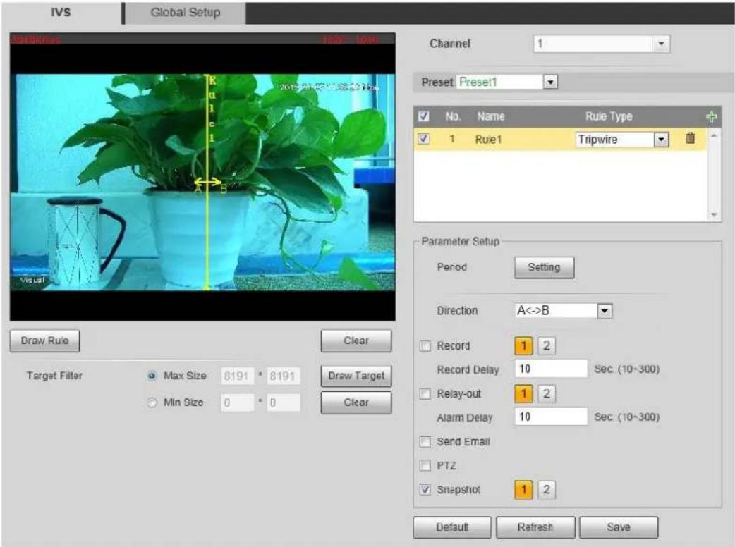
2) Click Draw Rule to draw a rule on surveillance image. Right-click to end drawing.

Click Clear to delete all the tripwires.
3) Select Maximum Size or Minimum Size and click Draw Target. Then you can drag the filter box's corner to make the box larger or smaller.

- An alarm is triggered only when size of the target that is crossing tripwire lies between the two filter boxes.
- When drawing a rule, you can select Maximum Size or Minimum Size and click Clear to delete a relevant filter box.
4) Set up tripwire parameters. See Table 4-22 for details.
Table 4-22 Tripwire parameter description
| Parameters | Description |
| Working Period | Define a period during which the alarm settings are active.1. Click Setting, and the period setting interface is displayed.2. Configure period.Method 1: Hold down and drag the left mouse button to select a period you need.Method 2: Select Setting > Event > Video Detection and click Setting on the right side of Period. An interface is displayed. In this interface, there are seven Settings altogether each of which corresponds to a day in a week. Select a Setting you want and there are six periods (period1-period6) below for you to pick up.1. Click Save to finish configuration of period. |
| Direction | Configure the target moving direction for tripwire alarm, you can select A->B, B->A and A<->B. |
| Record | Enable this function and alarm recording will be triggered when there is an alarm.To check and reset recorded videos' storage path, see "4.1.2.5 Configuring Storage Path".Two more conditions must be satisfied before alarm recording function works:You have enabled motion detection recording. See "4.7.1.1 Configuring Video Recording" for detailed operations.You have enabled auto recording. See "4.7.3 Configuring Record Control Parameters" for detailed operations. |
| Record Delay | The record keeps running for the set time after alarm is ended. |
| Relay-out | You can connect this relay-out port to such alarm devices as flashlights and alarm whistles. When an alarm is triggered, alarm devices connected to the relay-out port will work. Select the check box to enable this function. |
| Alarm Delay | The Alarm linkage keeps running for the set time after alarm is ended. |
| Send email | Enable this function. An e-mail will be delivered to the device user once the alarm is triggered.Set your e-mail first before enabling this function. See "4.2.5 Configuring SMTP" for detailed operations. |
| PTZ | Select the check box of PTZ and select an item from None, Preset, Tour, and Pattern in the Activation bar. Once an alarm is triggered, your PTZ will execute the item you have selected in the Activation bar.Set up PTZ first before enabling this function. See "3.2 PTZ" for detailed operations. |
| Snapshot | Enable this function and Snapshot will be triggered once there is an alarm.To check and set snapshots' storage path, see "4.1.2.5 Configuring Storage Path".Enable motion-detecting snapshots first before enabling this function. See "4.7.1.2 Configuring Snapshot" for detailed operations. |
Click OK to finish configuration. Step 4
4.4.2.2.2 Configuring Intrusion
When a target is crossing or appears in the area you have set up, an alarm is triggered.
Preparation
You have set up preset spots or tunnels' smart plan. See "4.4.1 Configuring Smart Plan" for detailed operations.
Procedure
Select Setting > Smart Thermal > IVS > IVS. Step 1
The IVS interface is displayed.
Select a preset in Preset bar. Step 2
The camera turns to the position.

This step is required only when preset dot function is carried on this interface.
Set up area invasion rules. Step 3
1) Click and then double-click the rule you have just added to set up its name.
Select Area Invasion as the type. See Figure 4-44.
Intrusion Figure 4-44
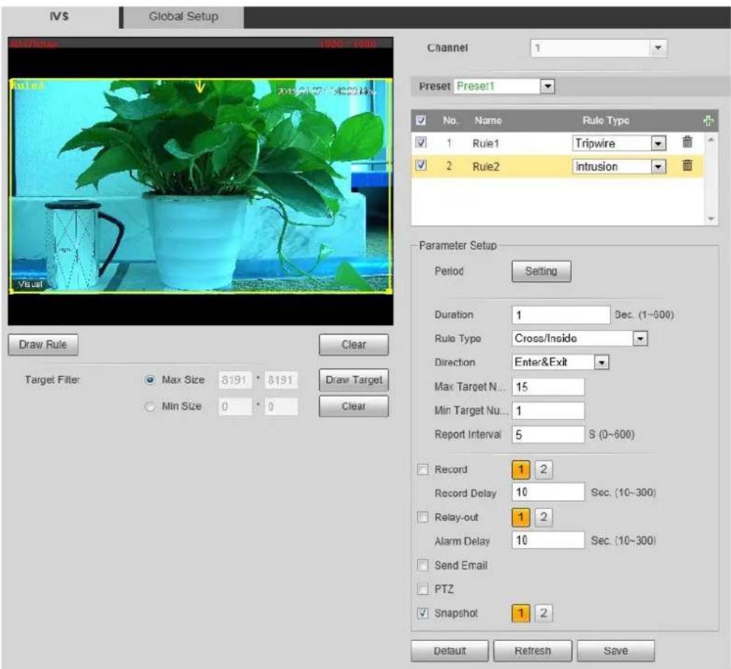
2) Click Draw Rule to draw a monitoring area on surveillance image. Right-click to end drawing.

- It requires certain residence time and moving space for the target to be confirmed, so leave some space around warning area during configuration and do not set it near obstacles.
- In Rule Type bar, when you select Cross/Inside, you need to modify your rule box to leave some detecting area around the box.
- Click Clear to delete monitoring area you have set up.
3) Select Maximum Size or Minimum Size and click Draw Target. Then you can drag the filter box's corner to make the box larger or smaller.

- An alarm is triggered only when size of target that is crossing your monitoring area lies between the two filter boxes.
- When drawing a rule, you can select Maximum Size or Minimum Size and click Clear to delete a relevant filter box.
4) Set up intrusion parameters. See Table 4-23 for details.
Table 4-23 Intrusion parameters
| Parameters | Description |
| Period | Define a period during which the alarm settings are active.1. Click Setting, and the period setting interface is displayed.2. Configure period.Method 1: Hold down and drag the left mouse button to select a period you need.Method 2: Select Setting > Event > Video Detection and click Setting on the right side of Period. An interface is displayed. In this interface, there are seven Settings altogether each of which corresponds to a day in a week. Select a Setting you want and there are six periods (period1-period6) below for you to pick up.3. Click Save to finish configuration of period. |
| Duration | The shortest time from placing an object in the detection area to an alarm is triggered. |
| Rule Type | Set area intrusion rules.Cross: An alarm is triggered when an object is entering or leaving the area.Inside: An alarm is triggered when an object appears in the area.Cross/Inside: An alarm is triggered when an object is entering, leaving or appears in the area. |
| Direction | Set this parameter when you select Cross or Cross/Inside as your Rule Type.You can select from Enters, Exits and Enters & Exits. |
| Max Target Number | Set this parameter when you select Inside or Cross/Inside as your Rule Type.Set a maximum target number and when targets' number in your area is larger than the number you have set, an alarm is frozen and does Not function. |
| Min Target Number | Set this parameter when you select Inside or Cross/Inside as your Rule Type.Set a minimum target number and when targets' number in your area is smaller than the number you have set, an alarm is frozen and does Not function. |
| Report Interval | Set this parameter when you selectInside or Cross/Inside as your Rule Type.Set the shortest time between a target appears and an alarm is triggered. |
| Record | Enable this function and alarm recording will be triggered when there is an alarm.To view and set storage path of recorded videos, see "4.1.2.5 Configuring Storage Path".The following two conditions must be satisfied before alarm recording function works:You have enabled motion detection recording. See "4.7.1.1 Configuring Video Recording" for detailed operations.You have enabled auto recording. See "4.7.3 Configuring Record Control Parameters" for detailed operations. |
| Record Delay | Set a length of time for the Device to delay turning off recording after an alarm is ended. |
| Relay-out | You can connect this relay-out port to such alarm devices as light and siren. When an alarm is triggered, those alarm devices will work. Select the check box to enable this function. |
| Alarm Delay | The Alarm linkage keeps running for the set time after alarm is ended. |
| Send Email | Select theSend Emailcheck box and an e-mail will be delivered to the device user once an alarm is triggered.Set your e-mail first before enabling theSend Emailfunction. See "4.2.5 Configuring SMTP" for detailed operations. |
| PTZ | Select the check box ofPTZand select an item fromNone,Preset,Tour,andPatternin theActivationbar. Once an alarm is triggered, your PTZ will execute the item you have selected in theActivationbar.Set up PTZ first before enabling this function. See "3.2 PTZ" for detailed operations. |
| Snapshot | Select theSnapshotcheck box to take a snapshot when there is an alarm.To view and set storage path of snapshots, see "4.1.2.5 Configuring Storage Path."To make the snapshot function take effect, you need to firstly enable motion-detection snapshots. See "4.7.1.2 Configuring Snapshot" for detailed operations. |
Click OK to finish configuration. Step 4
4.4.2.2.3 Configuring Abandoned Object
When the object is placed in the detection area longer than the defined period, the system activates alarms and links the configured actions.
Preparation
You have enabled detection to general behaviors. For detailed operations, see "4.4.1 Configuring Smart Plan."
Procedure
Select Setting > Smart Thermal > IVS > IVS. Step 1
The IVS interface is displayed.
Select a preset in Preset bar. Step 2
The camera turns to the position.

This step is required only when preset is supported by the Device.
Configure rules. Step 3
1) Click and then double-click the rule you have just added to set up its name. In the Rule Type list, select Abandoned Object. See Figure 4-45.
Abandoned object Figure 4-45

2) Click Draw Rule to draw a monitoring area on surveillance image. Right-click to end drawing.

- Pedestrians or cars might stay in your area and trigger an alarm. To filter this kind of alarm, you can set your targets' maximum size and ensure the size is smaller than people and vehicle.
- Click Clear to delete monitoring area you have set.
3) Select Max Size or Min Size, then click Draw Target, and then drag the filter box's corner to adjust the box's size to your requirement.

- An alarm is triggered only when size of abandoned objects lies between the two filter boxes.
- When drawing a rule, you can select Max Size or Min Size and click Clear to delete a relevant filter box.
4) Configure abandoned object parameters. See Table 4-24 for details.
Table 4-24 Abandoned object parameters
| Parameter | Description |
| Period | Define a period during which the alarm settings are active.1. Click Setting, and the period setting interface is displayed.2. Configure period.Method 1: Hold down and drag the left mouse button to select working period you need.Method 2: Select Setting > Event > Video Detection and click Setting on the right side of Period. An interface is displayed. In this interface, there are seven Settings altogether each of which corresponds to a day in a week. Select a Setting you want and there are six periods (period1-period6) below for you to pick up.3. Click Save to finish configuration of working period. |
| Duration | The shortest time from placing an object in the detection area to an alarm is triggered. |
| Record | Enable this function and alarm recording will be triggered when there is an alarm.To view and set storage path of recorded videos, see "4.1.2.5 Configuring Storage Path".The following two conditions must be satisfied before alarm recording function works:You have enabled motion detection recording. See "4.7.1.1 Configuring Video Recording" for detailed operations.You have enabled auto recording. See "4.7.3 Configuring Record Control Parameters" for detailed operations. |
| Record Delay | Set a length of time for the Device to delay turning off recording after an alarm is ended. |
| Relay-out | You can connect this relay-out port to such alarm devices as light and siren. When an alarm is triggered, those alarm devices will work. Select the check box to enable this function. |
| Alarm Delay | Set a length of time for the Device to delay turning off alarm after an event is actually ended. |
| Send Email | Select the Send Email check box and an e-mail will be delivered to the device user once an alarm is triggered.Set your e-mail first before enabling the Send Email function. See "4.2.5 Configuring SMTP" for detailed operations. |
| PTZ | Select the check box of PTZ and select an item from None, Preset, Tour, and Pattern in the Activation bar. Once an alarm is triggered, your PTZ will execute the item you have selected in the Activation bar.[IMAGE]Set up PTZ first before enabling this function. See "3.2 PTZ" for detailed operations. |
| Snapshot | Select the Snapshot check box to take a snapshot when there is an alarm.[IMAGE]To view and set storage path of snapshots, see "4.1.2.5 Configuring Storage Path".To make the snapshot function take effect, you need to firstly enable motion-detection snapshots. See "4.7.1.2 Configuring Snapshot" for detailed operations. |
Click Save to finish configuration. Step 4
4.4.2.2.4 Configuring Missing Object
When an object is taken away from the detection area and the absent time of the object is longer than the defined one, an alarm will be triggered and linked activities will be executed.
Preparation
You have set smart plans of presets or channels. See "4.4.1 Configuring Smart Plan" for detailed operations.
Procedure
Select Setting > Smart Thermal > IVS > IVS. Step 1
The IVS interface is displayed.
Select a preset in Preset bar. Step 2
The camera turns to the position.

This step is required only when preset is supported by the Device.
Set up rules about those missing objects Step 3
1) Click and then double-click the rule you have just added to set its name. In the Rule Type list, select Missing Object. See Figure 4-46.
Missing object Figure 4-46

2) Click Draw Rule to draw a monitoring area on surveillance image. Right-click to end drawing.

Click Clear to delete monitoring area you have set.
3) Select Max Size or Min Size, then click Draw Target, and then drag the filter box's corner to adjust the box's size to your requirement.

- An alarm is triggered only when size of the missing object lies between the two filter boxes.
- When drawing a rule, you can select Max Size or Min Size and click Clear to delete a relevant filter box.
4) Configure missing object parameters. See Table 4-25 for details.
Table 4-25 Missing object parameters
| Parameter | Description |
| Period | Define a period during which the alarm settings are active.1. Click Setting, and the period setting interface is displayed.2. Configure period.Method 1: Hold down and drag the left mouse button to select working period you need.Method 2: Select Setting > Event > Video Detection and click Setting on the right side of Period. An interface is displayed. In this interface, there are seven Settings altogether each of which corresponds to a day in a week. Select a Setting you want and there are six periods (period1-period6) below for you to pick.3. Click Save to finish configuration of working period. |
| Duration | The shortest time from placing an object in the detection area to an alarm is triggered. |
| Record | Enable this function and alarm recording will be triggered when there is an alarm.To view and set storage path of recorded videos, see "4.1.2.5 Configuring Storage Path".The following two conditions must be satisfied before alarm recording function works:You have enabled motion detection recording. See "4.7.1.1 Configuring Video Recording" for detailed operations.You have enabled auto recording. See "4.7.3 Configuring Record Control Parameters" for detailed operations. |
| Record Delay | Set a length of time for the Device to delay turning off recording after an alarm is ended. |
| Relay-out | You can connect this relay-out port to such alarm devices as light and siren. When an alarm is triggered, those alarm devices will work. Select the check box to enable this function. |
| Alarm Delay | Set a length of time for the Device to delay turning off alarm after an event is actually ended. |
| Send Email | Select theSend Emailcheck box and an e-mail will be delivered to the device user once an alarm is triggered.Set your e-mail first before enabling theSend Emailfunction. See "4.2.5 Configuring SMTP" for detailed operations. |
| PTZ | Select the check box ofPTZand select an item fromNone,Preset,Tour,andPatternin theActivationbar. Once an alarm is triggered, your PTZ will execute the item you have selected in theActivationbar.Set PTZ first before enabling this function. See "3.2 PTZ" for detailed operations. |
| Snapshot | Select theSnapshotcheck box to take a snapshot when there is an alarm.To view and set storage path of snapshots, see "4.1.2.5 Configuring Storage Path".To make the snapshot function take effect, you need to firstly enable motion-detection snapshots. See "4.7.1.2 Configuring Snapshot" for detailed operations. |
Click OK to finish configuration. Step 4
4.4.2.3 Configuring Global Setup
Preparation
You have set smart plans of presets or channels. See "4.4.1 Configuring Smart Plan" for detailed operations.
Procedure
Select Setting > Smart Thermal > IVS > Global Setup. Step 1
The Global Setup interface is displayed. See Figure 4-47.
Global setup Figure 4-47

Select a preset in Preset bar. Step 2
The camera turns to the position.

You need this step only when presets are supported in this Device.
Add detected area and excluded area. Step 3
1) Click Add Detect Region to draw a detected area on surveillance image. Right-click to end drawing.

Click Add Detect again to redraw.
2) Click Add Excluded Area to draw an excluded area on surveillance image. Right-click to end drawing.

- Click Delete Excluded Area to delete the excluded area.
- An excluded area takes effect only when it has been drawn in the detected area.
- Multiple excluded areas can be drawn in the detected area.
Step 4 Configure global setup parameters. See Table 4-26 for details.
Table 4-26 Global setup parameters
| Parameter | Description |
| Anti-Disturb Enable | Select the On check box to enable this function.This function is aimed at eliminating disturbance caused by shaking leaves or waving water. |
| Shadow Screen Enable | Select the On check box to enable this function.This function is aimed at eliminating an object's shadow and representing only the object itself in the object box; several objects with their shadows partly overlaid can be told separately. So this function can give user a precise clue of where the object really locates. However, if an object's part looks like the object's shadow, it's likely that this part will be identified as a shadow and eliminated. |
| Sensitivity | The larger this value is, the easier an alarm will be to be triggered by low-contrast or tiny objects. |
| Isotherm Filter | Select the On check box and set Upper Limit Threshold and Lower Limit Threshold on your own needs.This function is aimed at diminishing false alarms caused by waving water. |
| Tracking Overlap Rate | When overlap rate of an object at this moment and at earlier time is smaller than the rate you have set, this object can be detected and an alarm is triggered. |
| Valid Tracking Distance | Only when an object's moving distance is larger than valid tracking distance you have set, this object can be detected and an alarm is triggered. |
| Valid Tracking Time | Only when an object's moving time is larger than valid tracking time you have set, this object can be detected and an alarm is triggered. |
Click Save to finish configuration. Step 5
4.4.3 Configuring Fire Warning
The system will give out an alarm once a fire is detected.
Select Setting > Smart Thermal > Fire Warning. Step 1
The Fire Warning interface is displayed. See Figure 4-48.
Fire warning Figure 4-48
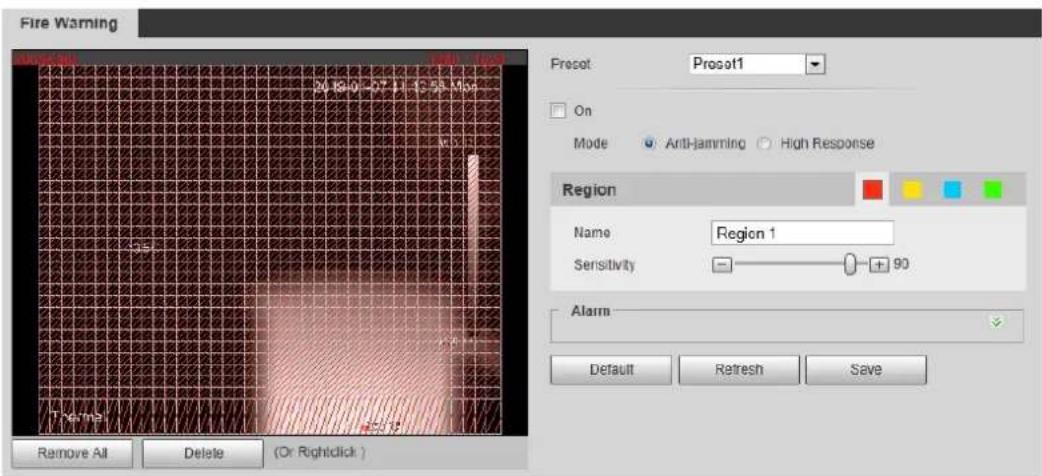
Select a preset. Step 2
The camera turns to the position.

This step is required only when preset is supported by your Device.
Select the On check box. Step 3
Set rules of fire warning. Step 4
1) Select fire warning mode on your own needs.

High response mode is your only option when you want your camera to detect any a hidden fire danger.
- Anti-jamming: Your camera will only detect those objects that are newly with high temperature and send off alarms. That means under Anti-jamming mode, a constantly high-temperature object (a boiler, for example) is excluded.
- High Response: Your camera will detect any a hidden fire danger and send off alarms.
2) Select a color in . Each color represents a certain area which
you can draw with your left mouse button. You can also give a name to the area you have drawn and set its sensitivity.

The larger the sensitivity is, the easier a fire will be triggered.
3) Set up fire warning parameters. See Table 4-27 for details.
Table 4-27 Fire warning parameters
| Parameter | Description |
| Period | Define a period during which the alarm settings are active.1. Click Setting, and the period setting interface is displayed.2. Configure period.Method 1: Hold down and drag the left mouse button to select working period you need.Method 2: Select Setting > Event > Video Detection and click Setting on the right side of Period. An interface is displayed. In this interface, there are seven Settings altogether each of which corresponds to a day in a week. Select a Setting you want and there are six periods (period1-period6) below for you to pick up.3. Click Save to finish configuration of working period. |
| Duration | The shortest time from placing an object in the detection area to an alarm is triggered. |
| Record | Enable this function and alarm recording will be triggered when there is an alarm.To view and set storage path of recorded videos, see "4.1.2.5 Configuring Storage Path".The following two conditions must be satisfied before alarm recording function works:You have enabled motion detection recording. See "4.7.1.1 Configuring Video Recording" for detailed operations.You have enabled auto recording. See "4.7.3 Configuring Record Control Parameters" for detailed operations. |
| Record Delay | Set a length of time for the Device to delay turning off recording after an alarm is ended. |
| Relay-out | You can connect this relay-out port to such alarm devices as light and siren. When an alarm is triggered, those alarm devices will work. Select the check box to enable this function. |
| Alarm Delay | Set a length of time for the Device to delay turning off alarm after an event is actually ended. |
| Send Email | Select theSend Emailcheck box and an e-mail will be delivered to the device user once an alarm is triggered.[IMAGE]Set your e-mail first before enabling theSend Emailfunction. See "4.2.5 Configuring SMTP" for detailed operations. |
| PTZ | Select the check box ofPTZand select an item fromNone,Preset,Tour,andPatternin theActivationbar. Once an alarm is triggered, your PTZ will execute the item you have selected in theActivationbar.[IMAGE]Set up PTZfirst before enabling this function. See "3.2 PTZ" for detailed operations. |
| Snapshot | Select theSnapshotcheck box to take a snapshot when there is an alarm.[IMAGE]To view and set storage path of snapshots, see "4.1.2.5 Configuring Storage Path.""To make the snapshot function take effect, you need to firstly enable motion-detection snapshots. See "4.7.1.2 Configuring Snapshot" for detailed operations. |
Click Save to finish configuration. Step 5
4.4.4 Configuring Hot Trace
You can enable Hot Trace to track spot with the highest temperature and spot with the lowest temperature.
Step 1 Select Setting > Smart Thermal > Hot Trace.
The Hot Trace interface is displayed. See Figure 4-49.
Hot trace Figure 4-49

Select the On check box. Step 2
Configure parameters of cold/hot spot tracking. See Table 4-28 for details. Step 3
Table 4-28 Parameters of hot trace
| Parameters | Description |
| Color Mode | Select a color for cold and hot spots.Auto: Select colors for the highest/lowest temperature automatically according to surveillance images.Manual: Define colors for the highest/lowest temperature. |
| Alarm Condition | Conditions under which an alarm is triggered.SingleSelect theHot Spot temperature more thancheck box and when the highest temperature is larger than the temperature you have set, an alarm is triggered.Select theCold Spot temperature less thancheck box and when the lowest temperature is smaller than the temperature you have set, an alarm is triggered.If you select both conditions above at one time, an alarm is triggered once any one condition is satisfied.CombinationOnly when the highest temperature is larger and the lowest temperature is smaller than the temperature you have set, an alarm is triggered. |
| Period | Define a period during which the alarm settings are active.ClickSetting,and the period setting interface is displayed.Configure period.Method 1: Hold down and drag the left mouse button to select working period you need.Method 2: SelectSetting > Event > Video Detectionand clickSettingon the right side ofPeriod.An interface is displayed. In this interface, there are sevenSettingsaltogether each of which corresponds to a day in a week. Select aSettingyou want and there are six periods (period1-period6) below for you to pick up.ClickSaveto finish configuration of working period. |
| Anti-Dither | Only one motion detection event is recorded within the time you have set. |
| Record | Enable this function and alarm recording will be triggered when there is an alarm.To view and set storage path of recorded videos, see "4.1.2.5 Configuring Storage Path".The following two conditions must be satisfied before alarm recording function works:You have enabled motion detection recording. See "4.7.1.1 Configuring Video Recording" for detailed operations.You have enabled auto recording. See "4.7.3 Configuring Record Control Parameters" for detailed operations. |
| Record Delay | Set a length of time for the Device to delay turning off recording after an alarm is ended. |
| Relay-out | You can connect this relay-out port to such alarm devices as light and siren. When an alarm is triggered, those alarm devices will work. Select the check box to enable this function. |
| Alarm Delay | Set a length of time for the Device to delay turning off alarm after an event is actually ended. |
| Send Email | Select theSend Emailcheck box and an e-mail will be delivered to the device user once an alarm is triggered.Set your e-mail first before enabling theSend Emailfunction. See "4.2.5 Configuring SMTP" for detailed operations. |
| PTZ | Select the check box of PTZand select an item from None, Preset, Tour, and Pattern in the Activation bar. Once an alarm is triggered, your PTZ will execute the item you have selected in the Activation bar.Set PTZ first before enabling this function. See "3.2 PTZ" for detailed operations. |
| Snapshot | Select theSnapshotcheck box to take a snapshot when there is an alarm.To view and set storage path of snapshots, see "4.1.2.5 Configuring Storage Path".To make the snapshot function take effect, you need to firstly enable motion-detection snapshots. See "4.7.1.2 Configuring Snapshot" for detailed operations. |
Click Save to finish configuration. Step 4
Effect of hot trace is as shown in Figure 4-50.

The thermal camera can be classified as temperature-measuring model and observation model according to whether it carries temperature-measuring function. Cold/Hot spot's temperature is not displayed on the Device of observing model.
Effect of hot trace Figure 4-50
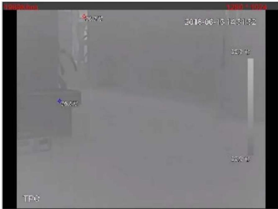
4.4.5 Configuring Pic in Pic
Put the thermal image that has shrunk on the visible image.
Step 1 Select Setting > Smart Thermal > Pic in Pic.
The Pic in Pic interface is displayed. See Figure 4-51.
Pic in pic Figure 4-51
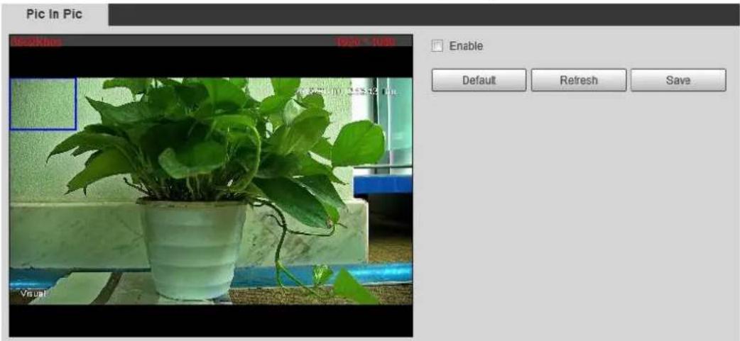
Select the Enable check box. Step 2
Step 3 Drag the blue box's angle to enlarge the box. Click in the box and drag your mouse to adjust the box's location.
Click Save to finish configuration. Step 4
4.4.6 Configuring Link Schedule
Step 1 Select Setting > Smart Thermal > Link Schedule.
The Link Schedule interface is displayed. See Figure 4-52.
Link schedule Figure 4-52

Configure periods for each weekday. Step 2

In Figure 4-52, you can hold your mouse's left button to directly drag a period bar for each weekday.
1) In Figure 4-52, click Setting next to the green bar and the dialogue box of Setting is displayed. See Figure 4-53.
Setting Figure 4-53

2) Select a weekday and a period. Then you can define the period.

When you select the check box of All, you're doing period settings towards all weekdays.
3) Click Save. You return to the Link Schedule interface.
Click Save to finish configuration. Step 3
Event 4.5
4.5.1 Configuring Video Detection
4.5.1.1 Configuring Motion Detection
When an object appears and moves fast enough to reach the sensitivity value you have set, the object will be detected and an alarm will be triggered.
Step 1 Select Setting > Event > Video Detection > Motion Detection.
The Motion Detection interface is displayed. See Figure 4-54.
Motion detection setting Figure 4-54

Select the Enable check box. Step 2 Configure a motion detection area. Step 3
1) Next to Area, click Setting. The Area interface is displayed. See Figure 4-55.
Area configuration Figure 4-55
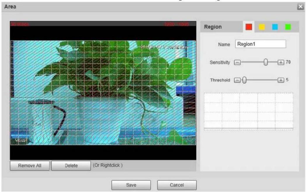
2) Set area name and select motion detection areas as needed. You can configure the sensitivity and mutation threshold. The threshold defines the allowed moving area for certain objects. The motion detection will not be triggered as long as those objects stay within the area.

- The higher the sensitivity value is, the easier the motion detection will be triggered; the lower the mutation threshold is, the smaller the allowed moving area for certain objects is, hence the easier the motion detection will be triggered.
- Different colors represent different area. For each area, you can set different sensitivity and mutation threshold.
- In the wave diagram, red line represents motion detection is triggered, and green line represents not.
3) Click Save to finish configuration.
Configure motion detection parameters. See Table 4-29 for details. Step 4
Table 4-29 Motion detection parameters
| Parameter | Description |
| Period | Define a period during which the alarm settings are active.1. Click Setting, and the period setting interface is displayed.2. Configure period.Method 1: Hold down and drag the left mouse button to select working period you need.Method 2: Select Setting > Event > Video Detection and click Setting on the right side of Period. An interface is displayed. In this interface, there are seven Settings altogether each of which corresponds to a day in a week. Select a Setting you want and there are six periods (period1-period6) below for you to pick up.3. Click Save to finish configuration of working period. |
| Anti-Dither | The system records only one motion detection event within the set time. |
| Record | Enable this function and alarm recording will be triggered when there is an alarm.To view and set storage path of recorded videos, see "4.1.2.5 Configuring Storage Path".The following two conditions must be satisfied before alarm recording function works:You have enabled motion detection recording. See "4.7.1.1 Configuring Video Recording" for detailed operations.You have enabled auto recording. See "4.7.3 Configuring Record Control Parameters" for detailed operations. |
| Record Delay | Set a length of time for the Device to delay turning off recording after an alarm is ended. |
| Relay-out | You can connect this relay-out port to such alarm devices as light and siren. When an alarm is triggered, those alarm devices will work. Select the check box to enable this function. |
| Alarm Delay | Set a length of time for the Device to delay turning off alarm after an event is actually ended. |
| Send Email | Select theSend Emailcheck box and an e-mail will be delivered to the device user once an alarm is triggered.[IMAGE]Set your e-mail first before enabling theSend Emailfunction. See "4.2.5 Configuring SMTP" for detailed operations. |
| PTZ | Select the check box ofPTZand select an item fromNone,Preset, Tour,andPatternin theActivationbar. Once an alarm is triggered, your PTZ will execute the item you have selected in theActivationbar.[IMAGE]Set PTZ first before enabling this function. See "3.2 PTZ" for detailed operations. |
| Snapshot | Select theSnapshotcheck box to take a snapshot when there is an alarm.[IMAGE]To view and set storage path of snapshots, see "4.1.2.5 Configuring Storage Path.""To make the snapshot function take effect, you need to firstly enable motion-detection snapshots. See "4.7.1.2 Configuring Snapshot" for detailed operations. |
____ Click Save to finish configuration. Step 5
4.5.1.2 Configuring Video Temper
When your camera lenses are masked, an alarm will be triggered.
Step 1 Select Setting > Event > Video Detection > Video Temper.
The Video Temper interface is displayed. See Figure 4-54.
Video temper Figure 4-56

Select the Enable check box. Step 2
Configure video temper parameters. See Table 4-29 for details. Step 3
Table 4-30 Parameters description
| Parameter | Description |
| Period | Define a period during which the alarm settings are active.1. Click Setting, and the period setting interface is displayed.2. Configure period.Method 1: Hold down and drag the left mouse button to select working period you need.Method 2: Select Setting > Event > Video Detection and click Setting on the right side of Period. An interface is displayed. In this interface, there are seven Settings altogether each of which corresponds to a day in a week. Select a Setting you want and there are six periods (period1-period6) below for you to pick up.3. Click Save to finish configuration of working period. |
| Record | Enable this function and alarm recording will be triggered when there is an alarm.To view and set storage path of recorded videos, see "4.1.2.5 Configuring Storage Path".The following two conditions must be satisfied before alarm recording function works:You have enabled motion detection recording. See "4.7.1.1 Configuring Video Recording" for detailed operations.You have enabled auto recording. See "4.7.3 Configuring Record Control Parameters" for detailed operations. |
| Record Delay | Set a length of time for the Device to delay turning off recording after an alarm is ended. |
| Relay-out | You can connect this relay-out port to such alarm devices as light and siren. When an alarm is triggered, those alarm devices will work. Select the check box to enable this function. |
| Alarm Delay | Set a length of time for the Device to delay turning off alarm after an event is actually ended. |
| Send Email | Select the Send Email check box and an e-mail will be delivered to the device user once an alarm is triggered.Set your e-mail first before enabling the Send Email function. See "4.2.5 Configuring SMTP" for detailed operations. |
| PTZ | Select the check box of PTZ and select an item from None, Preset, Tour, and Pattern in the Activation bar. Once an alarm is triggered, your PTZ will execute the item you have selected in the Activation bar.Set PTZ first before enabling this function. See "3.2 PTZ" for detailed operations. |
| Snapshot | Select the Snapshot check box to take a snapshot when there is an alarm.To view and set storage path of snapshots, see "4.1.2.5 Configuring Storage Path."To make the snapshot function take effect, you need to firstly enable motion-detection snapshots. See "4.7.1.2 Configuring Snapshot" for detailed operations. |
Click Save to finish configuration. Step 4
4.5.2 Configuring Audio Detection
Select Setting > Event > Audio detection. Step 1
The Audio Detection interface is displayed. See Figure 4-57.
Audio detection settings Figure 4-57

Configure parameters of audio detection. See Table 4-31 for details. Step 2
Table 4-31 Parameters of audio detection
| Parameters | Description |
| Input Abnormal | Enable this function and an alarm will be triggered when there is abnormal audio input. |
| Intensity Change | Enable this function and an alarm will be triggered when the change of sound intensity exceeds the threshold you have set. |
| Sensitivity | Volume change of input audio can be identified as audio abnormality only when volume change of input audio is larger than the lasting environment volume. You need to set the lasting environment volume on your own needs. |
| Threshold | Set the ambient sound intensity you need to filter. The louder the ambient noise is, the bigger this value should be, you can Adjust and test this option as needed. |
| Period | Define a period during which the alarm settings are active.1. Click Setting, and the period setting interface is displayed.2. Configure period.Method 1: Hold down and drag the left mouse button to select working period you need.Method 2: Select Setting > Event > Video Detection and click Setting on the right side of Period. An interface is displayed. In this interface, there are seven Settings altogether each of which corresponds to a day in a week. Select a Setting you want and there are six periods (period1-period6) below for you to pick up.3. Click Save to finish configuration of working period. |
| Anti-Dither | The system records only one audio detection event within the set time. |
| Record | Enable this function and alarm recording will be triggered when there is an alarm.To view and set storage path of recorded videos, see "4.1.2.5 Configuring Storage Path".The following two conditions must be satisfied before alarm recording function works:You have enabled motion detection recording. See "4.7.1.1 Configuring Video Recording" for detailed operations.You have enabled auto recording. See "4.7.3 Configuring Record Control Parameters" for detailed operations. |
| Record Delay | Set a length of time for the Device to delay turning off recording after an alarm is ended. |
| Relay-out | You can connect this relay-out port to such alarm devices as light and siren. When an alarm is triggered, those alarm devices will work. Select the check box to enable this function. |
| Alarm Delay | Set a length of time for the Device to delay turning off alarm after an event is actually ended. |
| Send Email | Select the Send Email check box and an e-mail will be delivered to the device user once an alarm is triggered.Set your e-mail first before enabling the Send Email function. See "4.2.5 Configuring SMTP" for detailed operations. |
| PTZ | Select the check box of PTZ and select an item from None, Preset, Tour, and Pattern in the Activation bar. Once an alarm is triggered, your PTZ will execute the item you have selected in the Activation bar.Set PTZ first before enabling this function. See "3.2 PTZ" for detailed operations. |
| Snapshot | Select the Snapshot check box to take a snapshot when there is an alarm. To view and set storage path of snapshots, see "4.1.2.5 Configuring Storage Path".To make the snapshot function take effect, you need to firstly enable motion-detection snapshots. See "4.7.1.2 Configuring Snapshot" for detailed operations. To view and set storage path of snapshots, see "4.1.2.5 Configuring Storage Path".To make the snapshot function take effect, you need to firstly enable motion-detection snapshots. See "4.7.1.2 Configuring Snapshot" for detailed operations. |
Click OK to finish configuration. Step 3
4.5.3 Configuring Temperature Alarm
You can set an alarm condition. When the temperature meets the defined alarm condition, an alarm is triggered and the linked activity is executed.

This function is available on select models, and the actual interface shall prevail.
Preparation
You have set the temperature measuring rules. See "4.6.1 Configuring Rules" for detailed operation.
Procedure
Select Setting > Event > Temperature Alarm. Step 1
The Temperature Alarm interface is displayed. See Figure 4-58.
Temperature alarm settings Figure 4-58
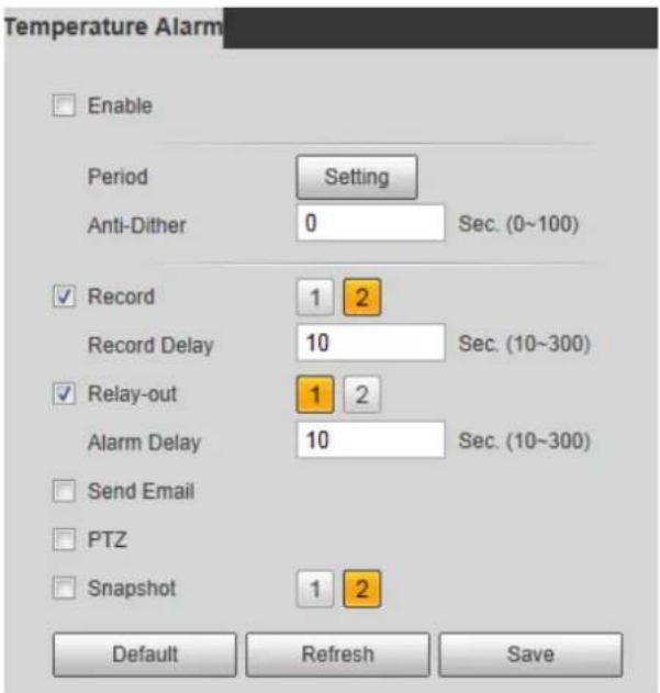
Select the Enable check box. Step 2
Configure parameters of temperature alarm. See Table 4-32 for details. Step 3
Table 4-32 Temperature alarm parameters
| Parameter | Description |
| Period | Define a period during which the alarm settings are active.1. Click Setting, and the period setting interface is displayed.2. Configure period.Method 1: Hold down and drag the left mouse button to select working period you need.Method 2: Select Setting > Event > Video Detection and click Setting on the right side of Period. An interface is displayed. In this interface, there are seven Settings altogether each of which corresponds to a day in a week. Select a Setting you want and there are six periods (period1-period6) below for you to pick up.3. Click Save to finish configuration of working period. |
| Anti-dither | Only one temperature alarm event is recorded within the time you have set. |
| Record | Enable this function and alarm recording will be triggered when there is an alarm.To view and set storage path of recorded videos, see "4.1.2.5 Configuring Storage Path".The following two conditions must be satisfied before alarm recording function works:You have enabled motion detection recording. See "4.7.1.1 Configuring Video Recording" for detailed operations.You have enabled auto recording. See "4.7.3 Configuring Record Control Parameters" for detailed operations. |
| Record Delay | Set a length of time for the Device to delay turning off recording after an alarm is ended. |
| Relay-out | You can connect this relay-out port to such alarm devices as light and siren. When an alarm is triggered, those alarm devices will work. Select the check box to enable this function. |
| Alarm Delay | Set a length of time for the Device to delay turning off alarm after an event is actually ended. |
| Send Email | Select the Send Email check box and an e-mail will be delivered to the device user once an alarm is triggered.Set your e-mail first before enabling the Send Email function. See "4.2.5 Configuring SMTP" for detailed operations. |
| PTZ | Select the check box of PTZ and select an item from None, Preset, Tour, and Pattern in the Activation bar. Once an alarm is triggered, your PTZ will execute the item you have selected in the Activation bar.Set PTZ first before enabling this function. See "3.2 PTZ" for detailed operations. |
| Snapshot | Select the Snapshot check box to take a snapshot when there is an alarm. To view and set storage path of snapshots, see "4.1.2.5 Configuring Storage Path".To make the snapshot function take effect, you need to firstly enable motion-detection snapshots. See "4.7.1.2 Configuring Snapshot" for detailed operations. To view and set storage path of snapshots, see "4.1.2.5 Configuring Storage Path".To make the snapshot function take effect, you need to firstly enable motion-detection snapshots. See "4.7.1.2 Configuring Snapshot" for detailed operations. |
Click Save to finish configuration. Step 4
4.5.4 Configuring Alarm
When there is an alarm from external devices, an alarm will be released and linked activities will be executed.
Select Setting > Event > Alarm. Step 1
The Alarm interface is displayed. See Figure 4-59.
Alarm settings Figure 4-59

Select the Enable check box. Step 2
Configure Relay activation parameters. For detailed description, see Table 4-33. Step 3
Table 4-33 Alarm parameters
| Parameters | Description |
| Relay-in | Select an external alarm device. |
| Period | Define a period during which the alarm settings are active.1. Click Setting, and the period setting interface is displayed.2. Configure period.Method 1: Hold down and drag the left mouse button to select working period you need.Method 2: Select Setting > Event > Video Detection and click Setting on the right side of Period. An interface is displayed. In this interface, there are seven Settings altogether each of which corresponds to a day in a week. Select a Setting you want and there are six periods (period1-period6) below for you to pick up.Click Save to finish configuration of working period. |
| Anti-dither | Only one temperature alarm event is recorded within the time you have set. |
| Sensor type | You can select from normally open (NO) and normally closed (NC). |
| Record | Enable this function and alarm recording will be triggered when there is an alarm.To view and set storage path of recorded videos, see "4.1.2.5 Configuring Storage Path."The following two conditions must be satisfied before alarm recording function works:You have enabled motion detection recording. See "4.7.1.1 Configuring Video Recording" for detailed operations.You have enabled auto recording. See "4.7.3 Configuring Record Control Parameters" for detailed operations. |
| Record Delay | Set a length of time for the Device to delay turning off recording after an alarm is ended. |
| Relay-out | You can connect this relay-out port to such alarm devices as light and siren. When an alarm is triggered, those alarm devices will work. Select the check box to enable this function. |
| Alarm Delay | Set a length of time for the Device to delay turning off alarm after an event is actually ended. |
| Send Email | Select theSend Emailcheck box and an e-mail will be delivered to the device user once an alarm is triggered.Set your e-mail first before enabling theSend Emailfunction. See "4.2.5 Configuring SMTP" for detailed operations. |
| PTZ | Select thePTZcheck box and select an item from None, Preset, Tour, and Pattern in the Activation bar. Once an alarm is triggered, your PTZ will execute the item you have selected in theActivationbar.Set PTZ first before enabling this function. See "3.2 PTZ" for detailed operations. |
| Snapshot | Select theSnapshotcheck box to take a snapshot when there is an alarm.To view and set storage path of snapshots, see "4.1.2.5 Configuring Storage Path".To make the snapshot function take effect, you need to firstly enable motion-detection snapshots. See "4.7.1.2 Configuring Snapshot" for detailed operations. |
____ Click Save to finish configuration. Step 4
4.5.5 Configuring Abnormality
Abnormality covers events of SD card, network and illegal access and burning warning.

The "No SD Card", "SD Card Error" and "Capacity Warning" events are available only on models that support SD card.
4.5.5.1 Configuring SD Card Abnormality Parameters
When any abnormality happens to the SD card, an alarm will be triggered and linked activities will be executed. SD card abnormality includes "No SD card", "SD Card Error" and "Capacity Warning."
Select Setting > Event > Abnormality > SD Card. Step 1
The SD Card interface is displayed. See Figure 4-60.
SD card Figure 4-60

Step 2 Select an event type.
Select the Enable check box. Step 3
Configure SD card abnormality parameters. For detailed description, see Table 4-34. Step 4
Table 4-34 SD card parameter description
| Parameters | Description |
| Minimum storage space in SD card | This parameter can be configured only when the event type is "capacity warning."Configure the free space percentage, and if the free space in the SD card is lower than the set percentage, the alarm is triggered. |
| Relay-out | You can connect this relay-out port to alarm devices such as light and siren. When an alarm is triggered, those alarm devices will work. Select the check box to enable this function. |
| Alarm Delay | Set a length of time for the Device to delay turning off alarm after an event is actually ended. |
| Send Email | Select the Send Email check box and an e-mail will be delivered to the device user once an alarm is triggered.[IMAGE]Set your e-mail first before enabling the Send Email function. See "4.2.5 Configuring SMTP" for detailed operations. |
____ Click Save to finish configuration. Step 5
4.5.5.2 Configuring Network Abnormality Parameters
When any abnormality happens to network, an alarm will be triggered and linked activities will be executed. Network abnormality includes "Disconnection" and "IP conflict."
Select Setting > Event > Abnormality > Network. Step 1
The Network interface is displayed. See Figure 4-61.
Network Figure 4-61

____ Select an event type. Step 2
Select the Enable check box. Step 3
Configure network abnormality parameters. See Table 4-35 for details. Step 4
Table 4-35 Network parameter description
| Parameter | Description |
| Record | Enable this function and alarm recording will be triggered when there is an alarm.To view and set storage path of recorded videos, see "4.1.2.5 Configuring Storage Path".The following two conditions must be satisfied before alarm recording function works:You have enabled motion detection recording. See "4.7.1.1 Configuring Video Recording" for detailed operations.You have enabled auto recording. See "4.7.3 Configuring Record Control Parameters" for detailed operations. |
| Record Delay | Set a length of time for the Device to delay turning off recording after an alarm is ended. |
| Relay-out | You can connect this relay-out port to such alarm devices as light and siren. When an alarm is triggered, those alarm devices will work. Select the check box to enable this function. |
| Alarm Delay | Set a length of time for the Device to delay turning off alarm after an event is actually ended. |
____ Click Save to finish configuration. Step 5
4.5.5.3 Configuring Illegal Access Parameters
If the password is continuously wrongly typed and the mistakes have reached the maximum you have set, an alarm will be triggered and linked activities will be executed.
Step 1 Select Setting > Event > Abnormality > Illegal Access.
The Illegal Access interface is displayed. See Figure 4-62.
Illegal access Figure 4-62
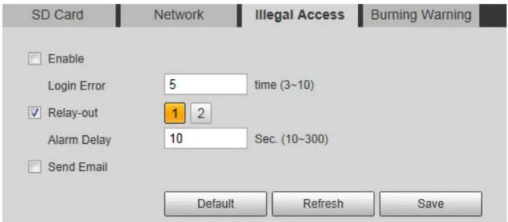
Select the Enable check box. Step 2
Configure illegal access parameters. See Table 4-36 for details. Step 3
Table 4-36 Illegal access parameter description
| Parameters | Description |
| Login error | The number of times that the login password is allowed to be wrongly entered for.When the login password has been wrongly entered for more than the set times, the account is locked. You need to wait 30 minutes before your account is unlocked. |
| Relay-out | You can connect this relay-out port to such alarm devices as light and siren. When an alarm is triggered, those alarm devices will work.Select the check box to enable this function. |
| Alarm Delay | Set a length of time for the Device to delay turning off alarm after an event is actually ended. |
| Send Email | Select theSend Emailcheck box and an e-mail will be delivered to the device user once an alarm is triggered.[IMAGE]Set your e-mail first before enabling theSend Emailfunction. See "4.2.5 Configuring SMTP" for detailed operations. |
Click Save to finish configuration. Step 4
4.5.5.4 Configuring Lenses Anti-Burning
Configure the lenses' anti-burning parameters and when the lenses are watching directly towards the sun and face the potential burning, the camera will automatically turn to other positions to avoid.

This function is supported on select models and the actual interface shall prevail.
Step 1 Select Setting > Event > Abnormality > Burning Warning.
The Burning Warning interface is displayed. See Figure 4-63.
Burning warning Figure 4-63

Select the Enable check box. Step 2
Step 3 Configure Sensitivity and Energy Threshold:
Sensitivity: Sensitivity for the camera to recognize whether the lenses are watching towards the sun. The larger the value is, the easier the camera will be to recognize the sun.
Energy Threshold: The minimum energy value of the object watched by the lenses. Select the energy threshold to filter the low-temperature objects and improve the identification accuracy.
Click Save to finish configuration. Step 4
4.6 Temperature Measuring Settings

Temperature measuring is available on select models and the actual interface shall prevail.
4.6.1 Configuring Rules
Configure temperature measuring rules and when alarm conditions are met, an alarm will be triggered.
4.6.1.1 Configuring Temperature Measuring Rules
Select Setting > Temperature > Rule > Parameter. Step 1 The Parameter interface is displayed. See Figure 4-64.
Parameter Figure 4-64

Configure temperature measuring rules and then parameters. Step 2
1) Click to add a rule.
See Figure 4-65.
Rule adding Figure 4-65

2) Double-click the rule you have just added to select measurement items and modify the measurement name.
3) Draw your rules.
- Select Measurement Items as Spot, and you can click a position on the surveillance image and a spot is formed.
- Select Measurement Items as Line, Rectangle or Ellipse, and you can hold the left mouse button to draw rules you need on the surveillance image.
- Select Measurement Items as Polygon, and you can hold the left mouse button to draw rules you need on the surveillance image. Right-click to end your drawing.

Select a rule you have drawn and click Redraw Rule. Then you can delete the rule and draw a new one.
4) Select the Open Local Config check box and configure parameters. See Table 4-37 for details.
Table 4-37 Parameter description of local configuration
| Parameters | Description |
| Target Radiation Coefficient | Radiation coefficient of targets that are shot by this Device. Ranges from 0.5 – 1. |
| Target Distance | Distance from the camera to targets that are shot. Ranges from 0m – 10000m. |
| Target Reflection Temperature | Temperature of targets that are shot by this Device. Ranges from -50 °C to 327.7 °C |
5) Enable the Relay-out check box and configure its parameters. See Table 4-38 for details.
Table 4-38 Parameter description of relay-out
| Parameter | Description |
| Alarm Results | Temperature's display items.Select Measurement Items as Spot, and average temperature and temperature slope will be displayed.Select Measurement Items as Line, Rectangle, Ellipse or Polygon, and maximum/minimum/average temperature, temperature slope and temperature difference are displayed. |
| By temperature difference, we mean the difference between maximum and minimum temperatures under rules you have set. By temperature slope, we mean temperature's varying rate under rules you have set. | |
| Alarm Condition | Set alarm conditions, covering Below, Match and Above. |
| Alarm Threshold Temperature | You can set this value when you select Alarm Results as Max, Min, Aver, or Temperature Difference.Ranges from -40 °C to 550 °C |
| Temperature Slope | You can set this value when you select Alarm Results as Slope.By temperature slope, we mean the temperature difference in each minute. Ranges from -600 °C/min – 600 °C/min. |
| Temperature Error | Set a temperature error value and if the alarm threshold temperature or temperature slope is within the value you have set, linked alarms will still be triggered. Ranges from -10 °C to 10 °C |
| Duration of Temperature | You can set a lasting time of abnormal temperature after which alarms will be triggered. Ranges from 0 – 1000s. |
Click Save to finish configuration. Step 3
You can watch temperature change under the rules you have set on surveillance images.
4.6.1.2 Configuring Temperature Contrast
You can compare temperature of spots, lines or area you have selected and display comparison results on surveillance images.
Preparation
You have set at least two temperature testing rules. See "4.6.1.1 Configuring Temperature Measuring Rules" for detailed operations.
Procedure
Select Setting > Temperature > Rule > Temp Contrast. Step 1
The Temp Contrast interface is displayed. See Figure 4-66.
Temperature contrast Figure 4-66

Set temperature contrast rules Step 2
1) Click to add a temperature contrast rule.
See Figure 4-67.
Temperature contrast rules adding Figure 4-67

2) Double-click to add a temperature contrast rule.
3) Set alarm parameters. See Table 4-39.
Table 4-39 Parameters
| Parameters | Description |
| Alarm Results | You can select from the following three options to determine a standard of triggering an alarm.Average temperature: Compare average temperatures of two rules.Maximum temperature: Compare maximum temperatures of two rules.Minimum temperature: Compare minimum temperatures of two rules.When one of the two rules refers to a spot, both maximum temperature and minimum temperature are actually average temperature. |
| Alarm Condition | Contains "lower", "matched" and "higher." |
| Alarm Threshold Temperature | Temperature of triggering an alarm. Ranges from 0 – 550 °C. |
____ Click Save to finish configuration. Step 3 On the left-side live image, you can view temperature contrast results of the object you have selected.
4.6.2 Configuring Global Setup
You can enable Temperature Switch, Isotherm and Color Code.
- Temperature Switch: A switch with which you can enable or disable temperature testing rules. Enable the Temperature Switch and the temperature testing rules you have set will be displayed on surveillance images.
- Isotherm: Used to highlight an object in images of high brightness. Isotherm is based on median temperature, with highest temperature and lowest temperature as its range. The part of an object whose temperature is higher than floor temperature will be represented in a bright color and the part of an object whose temperature is lower than floor temperature will be represented in a black/white color.
- Color Code: Enable this function, and a color code is displayed on the right side of surveillance images to show change of color between minimum temperature and maximum temperature.
Step 1 Select Setting > Temperature > Global Setup.
The Global Setup interface is displayed. See Figure 4-68.
Global setup Figure 4-68
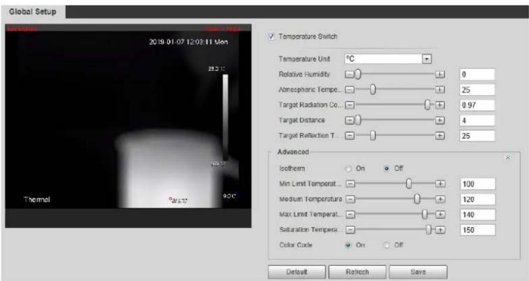
Step 2 Configure the global setup parameters. See Table 4-40 for details.
Table 4-40 Parameter description of global setup
| Parameter | Description |
| Temperature Switch | Select the check box to enable this function. |
| Temperature Unit | Includes °Cand °F. |
| Relative Humidity | Relative humidity of environment. Ranges from 0RH – 100 %RH. |
| Atmospheric Temperature | Temperature of our environment. Ranges from -50 °Qto 327.7 °C |
| Target Radiation Coefficient | Set Radiation coefficient of targets that are shot by this Device. Ranges from 0.5 – 1. |
| Target Distance | Distance from the camera to targets that are shot. Ranges from 0m – 10000m. |
| Target Reflection Temperature | Temperature of targets that are shot by this Device. Ranges from -50 °Qto 327.7 °C |
| Isotherm | Select the On check box.You have to make sure that floor temperature <= median temperature <= ceiling temperature <= saturation temperature. |
| Min Limit Temperature | When gain mode is under low-temperature mode, value ranges from -40 °Qto 150 °CWhen gain mode is under high-temperature mode, value ranges from -40 °Qto 600 °C |
| Medium Temperature | When gain mode is under low-temperature mode, value ranges from -40 °Qto 160 °CWhen gain mode is under low-temperature mode, value ranges from -40 °Qto 600 °C |
| Max Limit Temperature | When gain mode is under low-temperature mode, value ranges from -40 °Qto 160 °CWhen gain mode is under low-temperature mode, value ranges from -40 °Qto 600 °C |
| Saturation Temperature | When gain mode is under low-temperature mode, value ranges from -40°Qto 160°C.When gain mode is under low-temperature mode, value ranges from -40 °Qto 600 °C |
| Color Code | Select On to enable color code.A color code will be represented on the right side of surveillance images. |
____ Click Save to finish configuration. Step 3 Effect images are as shown in Figure 4-69, Figure 4-70, and Figure 4-71.
Temperature switch Figure 4-69

Isotherm Figure 4-70
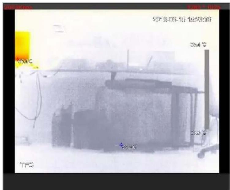
Color code Figure 4-71
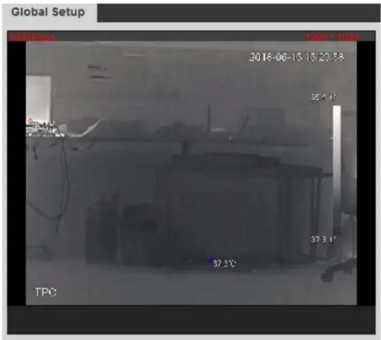
4.6.3 Exporting Heat Map
By exporting heat map, you can grasp temperature of every pixel on thermal images.
Step 1 Select Setting > Temperature > Heat Map.
The Heat Map interface is displayed. See Figure 4-72.
Heat map setting Figure 4-72

Click Export Heat Map. Step 2
Heat map files will be saved under the path you have set. For detailed operation of resetting the storage path, see "4.1.2.5 Configuring Storage Path."
Storage Management 4.7
4.7.1 Configuring Schedule
You can set schedule of recording, snapshotting, holidays.
[Non-Text]
If the record mode is Off in Storage > Record Control > Record Control interface, the system would not record video or snapshot as scheduled.
4.7.1.1 Configuring Video Recording
Set video recording, covering General, Motion and Alarm.
Select Setting > Storage > Schedule > Record. Step 1
The Record interface is displayed. See Figure 4-73.
Figure 4-73 Record
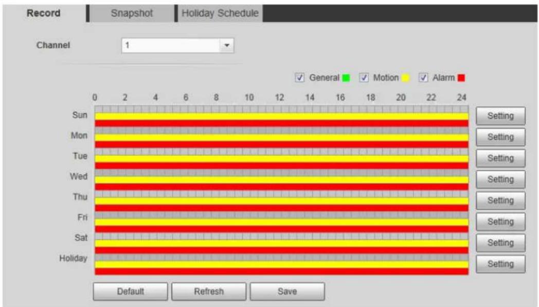
Select recording type and configure time period. Step 2

Select recording type, and then you can also press and hold the left mouse button to select the time period as needed in the chart.
1) Click the Setting for the day that you want to configure time period.
The Setting interface is displayed. See Figure 4-74.
Setting Figure 4-74
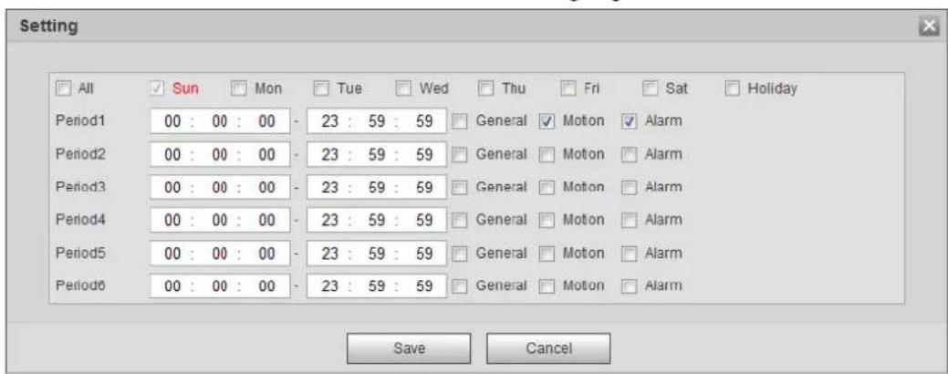
2) Select a day in a week and configure its period.

- There are 6 periods for each day.
- Select the All check box, and the entered time period will apply to the whole week. Sunday is selected by default, and you can select other days as needed.
3) Select the record type for the corresponding time period.
4) Click Save.
The system returns to the Record interface. Each color represents a video type. Green represents general video recording schedule, yellow represents video recording schedule under motion detection and red represents video recording schedule under alarm conditions.
4.7.1.2 Configuring Snapshot
Set video snapshot schedule, covering General, Motion and Alarm.
Select Setting > Storage > Schedule > Snapshot. Step 1
The Snapshot interface is displayed. See Figure 4-75.
Snapshot Figure 4-75
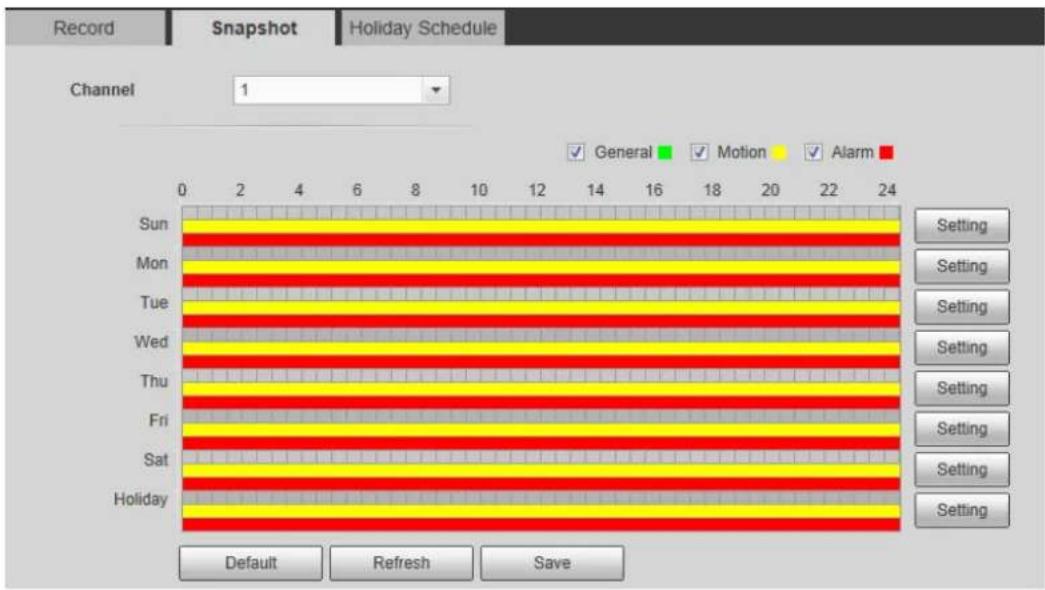
____ Select snapshot type and configure time period. Step 2

Select snapshot type, and then you can also hold down the left mouse button to select the time period in the chart as needed.
1) Click the Setting for the day that you need to configure time period.
The Setting interface is displayed. See Figure 4-76.
Settings Figure 4-76
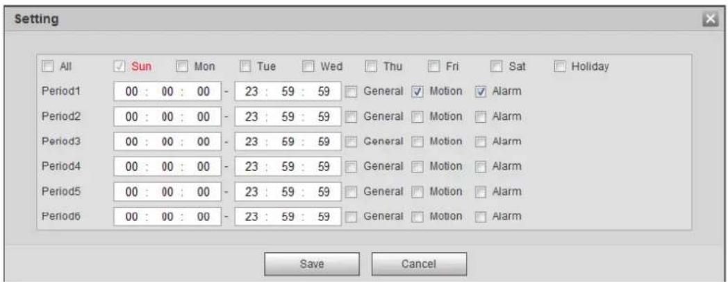
2) Select a day in a week and configure its time period.

- There are 6 time periods for each day.
- Select All, and the entered time period would apply to the whole week. Sunday is selected by default, and you can select other days as needed.
3) Select the snapshot type for the corresponding time period.
4) Click Save.
The system returns to the Snapshot interface. Each color matches with a certain Snapshot type. Green means General Snapshot, yellow means motion detection Snapshot and red means alarm Snapshot schedule.
Click Save to finish configuration. Step 3
4.7.1.3 Configuring Holiday Schedule
Select a day as your "holiday" and video recording/snapshots will be enabled at your "holiday."

- To use holiday recording function, you need to configure holiday recording schedule. For detailed operation, see "4.7.1.1 Configuring Video Recording."
- To use holiday snapshot function, you need to configure holiday record/snapshot schedule. For detailed operation, see "4.7.1.2 Configuring Snapshot."
Step 1 Select Setting > Storage > Schedule > Holiday Schedule.
The Holiday Schedule interface is displayed. See Figure 4-77.
Holiday schedule Figure 4-77

Select from record and snapshot. Step 2
Select days you need to set as your "holiday." Step 3
Those days with yellow color indicates they were set as holidays.
Click Save to finish configuration. Step 4
4.7.2 Device Storage
4.7.2.1 Configuring Storage Path
You can set video recording and snapshot's storage methods according to event types. You can save them in SD card, FTP or NAS.

Local storage is available only on models that support SD card.
Select Setting > Storage > Destination > Path. Step 1
The Path interface is displayed. See Figure 4-78.
Path Figure 4-78

Select different storage paths for the recorded videos and snapshots which belong to Step 2 different event types.
Table 4-41 Path parameters
| Parameter | Description |
| Event type | Select fromScheduled, Motion Detection and Alarm. |
| Local | Save in the internal SD card. |
| FTP | Save in the FTP server. |
| NAS | Save in the NAS (network attached storage). |
Click Save to finish configuration. Step 3
4.7.2.2 Configuring Local Storage
The system will display the internal SD card information. You can set it as Read Only or Read & Write; you can also Hot Swap or Refresh it.
Select Setting > Storage > Destination > Local, and the Local interface is displayed. See Figure 4-79.
- Select SD card you need to set and click Read Only. Then the SD card is set to read only.
- Select SD card you need to set and click Read & Write. Then the SD card is set to read& write.
- Select SD card you need to set and click Hot Swap. Then you can pull out the SD card.
- Select SD card you need to set and click Refresh. Then the SD card will be formatted.
Local storage setting Figure 4-79

4.7.2.3 Configuring FTP Server
You can set FTP server only when FTP is selected as the storage method in Path. When the network doesn't work, you can save all the files to the local SD card for emergency.
Select Setting > Storage > Destination > FTP. Step 1
The FTP interface is displayed. See Figure 4-80.
FTP settings Figure 4-80

Step 2 Select the Enable check box, and then select the service type.

SFTP service is recommended.
Step 3 Configure FTP parameters. See Table 4-42.
Table 4-42 FTP parameter description
| Parameters | Description |
| Server Address | The IP address of the SFTP or FTP server. |
| Port | The port of the SFTP or FTP server. |
| User name | The user name to log in the server. |
| Password | The password to log in the server. |
| Remote Directory | The destination path in the server. |
| Emergency (Local) | Select the Emergency (Local) check box, and when the FTP server does not work, all the files are saved to the internal SD card. |
____ Click Save to finish configuration. Step 4 Click Test to check whether the server has been properly connected.
4.7.2.4 Configuring NAS Server
This function can be enabled only when NAS has been selected as destination path. Select NAS interface and you can save files in NAS server.
Select Setting > Storage > Destination > NAS. Step 1
The NAS interface is displayed. See Figure 4-81.
NAS settings Figure 4-81

Select the Enable check box. Step 2
Configure NAS parameters. See Table 4-43 for details. Step 3
Table 4-43 NAS parameters
| Parameter | Description |
| Server Address | The IP address of the NAS server. |
| Remote Directory | The destination path in the NAS server. |
Click Save to finish configuration. Step 4
4.7.3 Configuring Record Control Parameters
This chapter introduces configurations including pack duration, pre-event record, disk full, record mode and record stream.
Select Setting > Storage > Record Control. Step 1
The Record Control interface is displayed. See Figure 4-82.
Record control settings Figure 4-82

Configure record control parameters. See Table 4-44 for details. Step 2
Table 4-44 Record control parameter description
| Parameters | Description |
| Pack Duration | The duration of each file pack. |
| Pre-event Record | The time period for which the system records video before alarm, if the value is 5, then the system records video for 5 seconds before alarm starts and save it.If theRecord Modeis Offand the record activity has been linked with alarm or motion detection, the system will still save the pre-event video. |
| Disk Full | The recording strategy when the disk is full.Stop: The system stops recording when the disk is full.Overwrite: The system overwrites the oldest files and keep recording when the disk is full. |
| Record Mode | At the record mode, if you selectManual, the system starts video recording; if you selectAuto, the system records video as time period scheduled; if you selectOff, video recording will not start. |
| Record Stream | Includes main stream and sub stream. |
Click Save to finish configuration. Step 3
System Management 4.8
4.8.1 General Settings
4.8.1.1 Configuring General Information
Configure device name, language and video standard.
Select Setting > System > General > General. Step 1
The General interface is displayed. See Figure 4-83.
General Figure 4-83

Step 2 Configure general parameters. See Table 4-45.
Table 4-45 General parameter description
| Parameter | Description |
| Device name | The name of the device.Each device has different name. |
| Language | Select system language. |
| Video Standard | Select video standard from PAL and NTSC. |
Click Save to finish configuration. Step 3
4.8.1.2 Configuring Date & Time
You can set up Date and Time format, Time zone, Current Time, DST (Daylight Saving Time) or NTP server.
Select Setting > System > General > Date & Time. Step 1
The Date & Time interface is displayed. See Figure 4-84.
Date & Time Figure 4-84

Configure Date & Time parameters. See Table 4-46 for details. Step 2
Table 4-46 Date & Time parameters
| Parameter | Description |
| Date Format | Date format. |
| Time Format | Configure the Time format, you can select from 24-Hour or 12-Hour. |
| Time zone | Configure the Time zone that the device is at. |
| Current Time | Configure system time.Click "Sync PC", and the system time changes to the time on PC. |
| DST | Enable DST as needed.Select the check box to enable daylight saving time. Select "DST", and then configure start time and end time of DST with dates or days of the week. |
| NTP | When you need the Device to transmit its time to NTP server, you can select the NTP check box to enable it. |
| Server | IP address or domain name of the NTP server. |
| Port | Port number of the FTP server. |
| Interval | Time gap of device's transmission of its current time to NTP server. |
Click Save to finish configuration. Step 3
4.8.1.3 Configuring GPS
Fill in the camera's GPS information in the web to remind you where your camera locates.
Also, automatically sent to the management platform, the GPS information can be viewed on the platform to help the platform operator track your camera.

This function is supported on select models and the actual interface shall prevail.
Step 1 Select Setting > System > General > GPS.
The GPS interface is displayed. See Figure 4-85.
GPS Figure 4-85

Step 2 Fill in your camera's LON, LAT and Altitude information.
Click Save to finish configuration. Step 3
4.8.2 User Management
Managing users and groups are only available for administrator users.
- The max length of the user or group name is 15 characters which can only be consisted of letters, numbers and underlines.
- The password must have 8 to 32 digits and at the same time have at least two forms (There are four password forms altogether: capital letter, lowercase letter, number and special characters. "", "", ";", ";", and "&" are not covered in special characters.) Administrator users can modify all the uses' password.
- You can have 19 users and 8 groups at most.
- You can manage users through single user or group, duplicate user names or group names are not allowed. A user can be in one group at a time and the group users can own authorities within group authority range.
• Online users cannot modify their own authority.
- There is one admin by default which has highest authority.
- Select "Anonymous login", and then log in with only IP address instead of user name and password. Anonymous users only have preview authorities. During Anonymous login, Click logout, and then you can log in with other username.
4.8.2.1 Adding a Group
You have two groups named admin and user by default, you can add new group, delete added group or modify group authority and memo.
Step 1 Select Setting > System > Account > Account > Group Name.
The Group Name interface is displayed. See Figure 4-86.
User group Figure 4-86
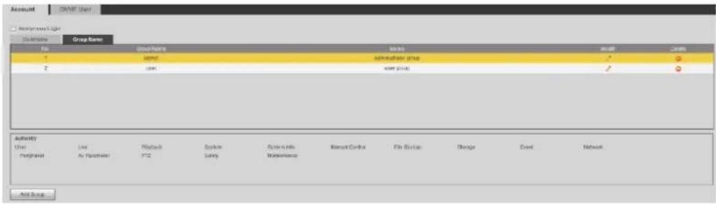
Click Add Group. Step 2
The Add Group interface is displayed. See Figure 4-87.
Add Group Figure 4-87

Enter Group name and memo. Then select Group authorities. Step 3
Click Save to finish configuration. Step 4
The newly added group displays in the group name list. See Figure 4-88.

- After adding group, click 🔍 to modify group memo or authorities; click 🔍 to delete the added group, admin group and user group cannot be deleted.
- Click in the row of admin group or user group to modify group memo.
User group added. Figure 4-88

4.8.2.2 Adding a User
You are admin user by default, and you can add user, delete added users or modify their password.
Select Setting > System > Account > Account. Step 1
The Account interface is displayed. See Figure 4-89.
Figure 4-89 User settings
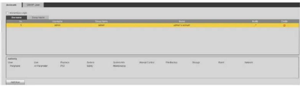
Click Add User. Step 2
The Add User interface is displayed. See Figure 4-90.
Add user Figure 4-90

Configure parameters. See Table 4-47. Step 3
Table 4-47 User parameter description
| Parameter | Description |
| Username | User's unique identification You cannot use existing user name. |
| Password | Enter password and confirm it.The two items must be the same. |
| Confirm Password | |
| Group name | The group that users belong to. Each group has different authorities. |
| Memo | Describes the user. |
| Authority | Select authorities as needed.It is recommended to give less authority to normal users than premium users. |
Click Save to finish configuration. Step 4
The newly added users are displayed in the user list.

- After adding user, click 🔍 to modify password, group, memo or authorities;
click to delete the added user, admin user cannot be deleted. - Click in the admin row to modify user name and email address.
4.8.2.3 Modifying User Password
For data security, it's strongly recommended that you change the default password of the Device and modify it regularly. Also, it's recommended that you adopt a complicated and strong password.
Step 1 Select Setting > System > Account > Account > Username.
The Username interface is displayed. See Figure 4-91.
Username Figure 4-91

Click . Step 2
The Modify User interface is displayed. See Figure 4-92.
Modify user (1) Figure 4-92

Select the Modify Password check box. Step 3
More settings are displayed. See Figure 4-93.
Modify user (2) Figure 4-93

____ Type old password. Type new password and confirm it. Step 4

The password must have 8 to 32 digits and at the same time have at least two of the four types: capital letter, lowercase letter, number and special characters.
Click Save to finish password modification. Step 5
4.8.3 Adding ONVIF User
Step 1 Select Setting > System > Account > ONVIF User.
The ONVIF User interface is displayed. See Figure 4-94.
ONVIF user Figure 4-94

Click Add User. Step 2
The Add User interface is displayed. See Figure 4-95.
Add user Figure 4-95
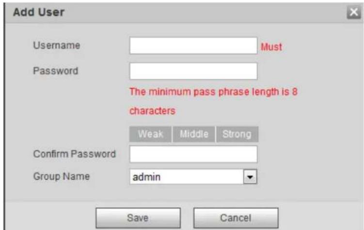
Enter username, password and confirm the password. Then, select group name. Step 3 Click Save to finish configuration. Step 4
4.8.4 Safety Management
Set RTSP authentication, IP filter, system service and HTTPS to secure data transmission and prevent data leakage.
4.8.4.1 Configuring RTSP Authentication
RTSP (Real Time Streaming Protocol) is to secure transmission of streaming media.
Step 1 Select Setting > System > Security > RTSP Authentication.
The RTSP Authentication interface is displayed. See Figure 4-96.
RTSP authentication Figure 4-96

Select an authentication mode. Step 2
Click Save. Step 3
4.8.4.2 Configuring IP Filter
To secure the network environment and protect your data, you can use IP filter to set who can and who cannot access your device.
- White list: Only users whose IP/MAC are on the white list can access your device.
- Black list: Only users whose IP/MAC are on the black list cannot access your device.
- Only when IP addresses of both your device and your PC are located in the same LAN, can MAC verification takes effect.

- When accessing through WAN, you can only use MAC of your router to limit MAC verification.
- You cannot enable white list and black list at the same time.
- You cannot add your device IP/MAC to the white list.
Select Setting > System > Safety > IP Filter. Step 1
The IP Filter interface is displayed. See Figure 4-97.
IP filter Figure 4-97
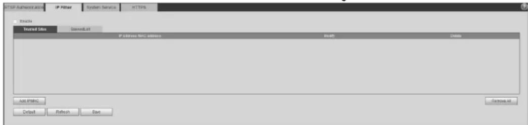
Select the check box of Enable. Step 2
- Add an IP/Mac address to the white list.
1) Click the Trusted Sites tab.
The Trusted Sites interface is displayed.
2) Click Add IP/MAC.
The dialogue box of Add IP/MAC is displayed.
3) Set IP/MAC address. See Table 4-48.
Table 4-48 IP/MAC address parameters description (trusted sites)
| Parameter | Description |
| IP address | IP address you are going to authorize. |
| IP segment | Start address and end address of the IP segment. |
| MAC address | MAC address you are going to authorize. |
4) Click Save.
- Add an IP/Mac address to the black list.
1) Click the Banned List tab.
The Banned List interface is displayed.
2) Click Add IP/MAC.
The dialogue box of Add IP/MAC is displayed.
3) Set IP/MAC address. See Table 4-49.
Table 4-49 IP/MAC address parameters description (banned list)
| Parameter | Description |
| IP address | IP address you are going to prohibit. |
| IP segment | Start address and end address of the IP segment. |
| MAC address | MAC address you are going to prohibit. |
4) Click Save.
Click Save to finish configuration. Step 3
4.8.4.3 Configuring System Service
You can set functions such as SSH, password reset, CGI service, Onvif service, genetec service, audio and video transmission encryption and mobile push.
Select Setting > System > Safety > System Service. Step 1
The System Service interface is displayed. See Figure 4-98.
Figure 4-98 System service
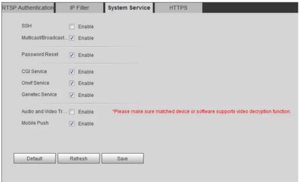
Step 2 Enable functions on the System Service interface. See Table 4-50.
Table 4-50 System service parameters description
| Parameter | Description |
| SSH | Disabled by default.SSH (Secure Shell) can encode your data for its transmission. By this way, data leakage can be prevented when you manage your device remotely. |
| Password Reset | Enabled by default.[IMAGE]If you choose to disable this function, then you can only restore hardware to reset password. |
| CGI Service | Enabled by default.Enable CGI (Common Gateway Interface) and then you can use your browser to get data from the server. |
| Onvif Service | Enabled by default.Enable Onvif service to connect your device to network video products (front ends of both vidicons and video recorders, and video recorders included) by other manufacturers. |
| Genetec Service | Enabled by default. |
| Audio and Video Transmission Encryption | Disabled by default.[IMAGE]If you enable this function, ensure the matching devices or software can decode audio and video you have encoded.Transmission of audio and video between your device and the third-party platform cannot be encoded. So, for data security, we recommend you to disable CGI service and Onvif service. |
| Mobile Push | Enabled by default. Snapshots under alarm condition can be delivered to your phone. |
Click Save. Step 3
4.8.4.4 Configuring HTTPS
With HTTPS, you can install customized certificates or signed certificates. You can also obtain and install a root certificate.
After installing customized certificates or signed certificates to your device, you need to install a root certificate to your PC. By this, your PC will log in the Device normally through HTTPS and guarantee your data security.
4.8.4.4.1 Creating and Installing Customized Certificates
Select Setup > Network > HTTPS. Step 1 The HTTPS interface is displayed. See Figure 4-99.
HTTPS Figure 4-99
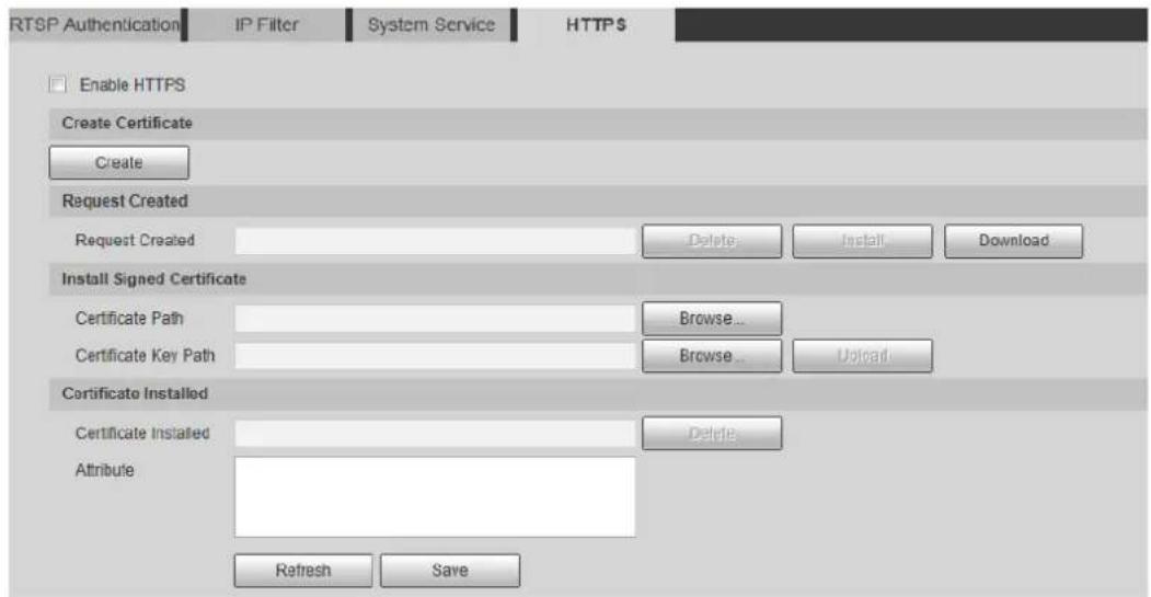
____ Create a certificate. Step 2
1) Click Create.
The dialog box of HTTPS is displayed. See Figure 4-100.

2) Configure HTTPS parameters. See Table 4-51.
Table 4-51 Parameters description
| Parameter | Description |
| Country | Abbreviation of a country. Limited to 2 capital letters. |
| IP or Domain Name | IP address or domain name of your device |
| Validity period | Validity period of the certificate. |
| Province | Province where you use this certificate. |
| Location | Location where you use this certificate. |
| Organization | Organization that uses this certificate. |
| Organization Unit | Name of organization unit that uses this certificate. |
| Email of a person or a company who uses this certificate. |
3) Click Create.
Requests created will be displayed.
Step 3 Click Install to start installation. After that, certificate property will be displayed in the Certificate Installed bar of the HTTPS interface.

Click Delete near the Certificate Installed bar of the HTTPS interface to delete an installed certificate.
Click Save to store the root certificate. Step 4
Install the root certificate. Step 5
1) Double-click you have saved.
The dialog box of Certificate is displayed. See Figure 4-101.
Certificate Figure 4-101
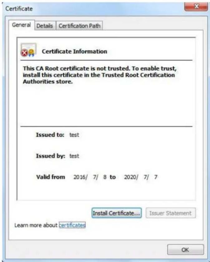
2) Click Install Certificate.
The Certificate Import Wizard interface is displayed. See Figure 4-102. Certificate import wizard Figure 4-102

3) Click Next.
The certificate store selection interface is displayed.
Certificate store Figure 4-103

4) Select "Place all certificates in the following store." Click Browse and set the "Trusted Root Certification Authorities" as certificate store.
5) Click Next.
The certificate import completing wizard is displayed. See Figure 4-104. Certificate import wizard completing Figure 4-104

6) Click Finish.
The security warning interface is displayed. See Figure 4-105.
Security warning Figure 4-105

7) Click Yes.
The system pops up a messaged that indicates the import was successful. See Click OK to finish certificate importing.
Successful import prompt Figure 4-106

8) Click OK to finish installation of root certificate.
Enable HTTPS and a prompt that the Device needs to be rebooted is displayed. Step 6 After your device reboots, type IP address of the Device in your browser and access the Device through HTTPS protocol.
4.8.4.4.2 Installing Signed Certificate
Get a signed certificate and its password from the digital signature institute. And import the certificate and its password to the Device.
Select Setting > Network > HTTPS. Step 1
The HTTPS interface is displayed. See Figure 4-107.
HTTPS Figure 4-107

Install a certificate that has been signed. Step 2
1) Click Browse on the right side of Certificate Path bar to select a certificate you are to upload.
2) Click Browse on the right side of Certificate Key Path bar to select the certificate password you are to upload.
Click Upload. Step 3
Installation begins. After that, certificate property will be displayed in the Certificate Installed bar of the HTTPS interface.

Click Delete near the Certificate Installed bar of the HTTPS interface to delete a certificate installed.
Click Save to store the root certificate. Step 4
Install the root certificate. Step 5
1) Click you have saved.
The dialog box of Certificate is displayed. See Figure 4-108.
Certificate Figure 4-108

2) Click Install Certificate.
The Certificate Import Wizard interface is displayed. See Figure 4-109. Certificate import wizard Figure 4-109

3) Click Next.
The certificate store selection interface is displayed. See Figure 4-110.
Certificate store Figure 4-110

4) Select "Place all certificates in the following store." Click Browse and set the trusted root certificate authority as certificate store.
5) Click Next.
The certificate import completing wizard is displayed. See Figure 4-111. Certificate import wizard completing Figure 4-111

6) Click Finish.
The security warning interface is displayed. See Figure 4-112.
Security warning Figure 4-112

7) Click Yes.
The system pops up a messaged that indicates the import was successful. See
Figure 4-113. Click OK to finish certificate importing.
Successful import prompt Figure 4-113

8) Click OK to finish installation of root certificate.
Enable HTTPS and a prompt that the Device needs to be rebooted is displayed. Step 6 After your device reboots, type IP address of the Device in your browser and access the Device through HTTPS protocol.
Maintenance Requirements 5.1
For the system's good and safe running, it's recommended to manage and maintain the system, backup files with the following methods.
- Check surveillance images regularly.
- Clear regularly user and user group information that are not frequently used.
- Modify your password every 3 months.
- Check your system logbook regularly. Handle problems as soon as possible.
- Backup your configuration of system regularly.
- Regularly check your files and delete the old ones.
- Upgrade firmware regularly.
Auto Maintenance 5.2
You can configure settings such as "time of when to self-reboot" "rebooting device manually" and "deleting files automatically."
5.2.1 Rebooting Device
Step 1 Select Setting > System > Auto Maintain.
The Auto Maintain interface is displayed. See Figure 5-1.
Auto maintain Figure 5-1

Step 2 Reboot this Device.
- Auto reboot: Select Auto Reboot and set a reboot time you need. Then click Save.
- Manual reboot: Click Manual Reboot and a dialogue box is displayed. Click OK in this dialogue box and your Device is rebooted at once.
5.2.2 Deleting Old Files
You can enable this function to delete recorded videos or images saved in SD card, FTP or NAS server regularly according to the time gap you have set.
Select Setting > System > Auto Maintain. Step 1 The Auto Maintain interface is displayed. See Figure 5-2.
Auto maintain Figure 5-2

Step 2____ Enable Auto Delete Old Files and select on your own the time gap of deleting the old files. Ranges from 1 to 31 day(s). ____ Click OK to finish configuration. Step 3
5.3 Backing Up and Restoring
5.3.1 Importing and Exporting

Files that are exported do not contain presets. To import and export presets, see "3.2.1.4
Configuring Preset Backup" and "3.2.2.4 Configuring Preset Backup."
Select Setting > System > Import/Export. Step 1
The Import/Export interface is displayed. See Figure 5-3.
Import/Export Figure 5-3

____ Import/Export files. Step 2
- Click Export and paths of backing up files are displayed.
- Click Import to import files that you have exported and backed up.
5.3.2 Default Settings

Be careful when implementing operations such as “restored to default” and “restored to factory default”. The operations will result in data loss.
Select Setting > System > Default. Step 1
The Default interface is displayed. See Figure 5-4.
Default setting Figure 5-4

____ Restore the Device to default setting. Step 2
- Click Default, and all the configurations except IP Address and Account are reset.
- Click Factory Default, and all the configurations are reset.
Upgrading Firmware 5.4

- If a wrong upgrade file has been used, please reboot the device, otherwise some functions might not work properly.
- When upgrading, do not cut off power/network, reboot or turn off the Device.
Select Setting > System > Upgrade. Step 1
The Upgrade interface is displayed. See Figure 5-5.
Figure 5-5 Upgrade

____ Select an upgrading method you need and upgrade the system. Step 2
- File Upgrade
1) Click Browse, and upload upgrade file. The upgrade file should be a .bin file.
2) Click Upgrade to start the process.
- Online Upgrade

Only when this thermal camera and your computer are both connected to network, can online upgrading be implemented.
Detect your system version.
Auto detection: Select Auto-check for updates and click Save. The version is detected automatically.
◇ Manual detection: Select Manual Check and the system begins to check the version information.
Version Information 5.5
View device hardware information, system version and web version.

Versions of different devices might vary, and the actual product shall prevail.
Select Setting > Information > Version, and the Version interface is displayed. See Figure 5-6.
Figure 5-6 Version
| Version | |
| Device Type | TPC-BF5400 |
| System Version | 2.622.0000000.0.R, Build Date: 2018-05-02 |
| WEB Version | 3.2.1.574049 |
| ONVIF Version | 16.12(V2.4.2.549803) |
| S/N | 4D0184AYAK0BFC8 |
| ThermalCamera Version | 2018.4.18 |
| Copyright 2018, all rights reserved. | |
System Log 5.6
5.6.1 Searching System Logs
The log type includes "all, system, setting, data, event, record, account and safety."
Select Setting > Information > Log. Step 1
The Log interface is displayed. See Figure 5-7.
Figure 5-7 Log
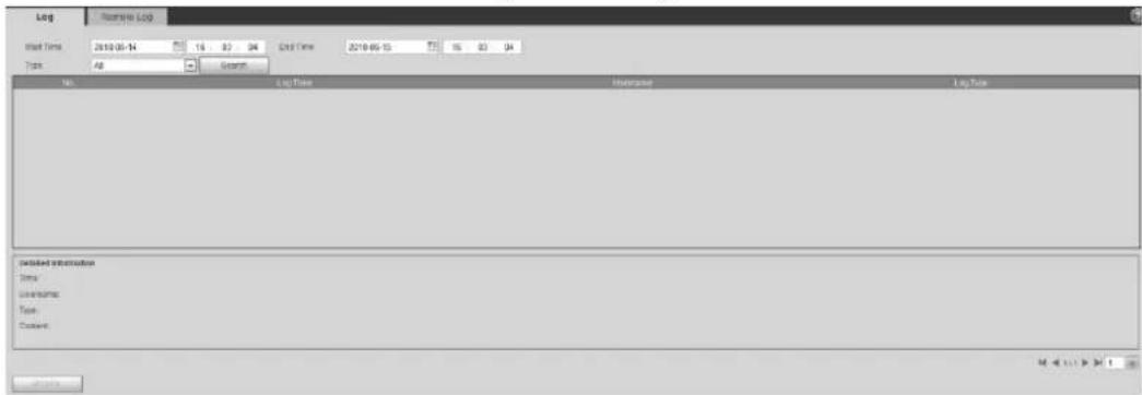
Set start time and end time, and then select log type. Step 2
Table 5-1 Parameter description of system log
| Parameters | Description |
| Start TimeEnd Time | Select a time period which you want to search.The earliest start time is January 1, 2000, and the latest end time is December 31, 2037. |
| Type | The log type includes "all, system, setting, data, event, record, account and safety."All: All log information.System: Includes program launch, force exit, exit, program reboot, device turn off/reboot, system reboot and system upgrade.Setting: Includes save configuration and delete configuration file.Data: Includes configure disk type, erase data, hot swap, FTP state, NAS state, record mode, SD card error and hard disk error.Event (Records events such as video detection, smart plan, alarm and abnormality): Includes event start and event end.Record: Includes file access, file access error and file search.User Management: Includes log in, log out, add user, delete user, modify user, add group, delete group and modify group.Safety: Includes password reset and IP filter. |
Click Search. Step 3
The needed logs are displayed. See Figure 5-8.
- Click a log, and then you can view the detailed information in Detailed Information area.
- Click Backup, and then you can back up all the found logs to your PC.
Log information Figure 5-8
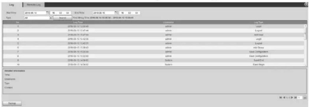
5.6.2 Remote View
Enable this function to remotely check logs in your device.
Select Setting > Information > Log. Step 1
The Remote Log interface is displayed. See Figure 5-9.
Remote Log Figure 5-9

Select the Enable check box. Step 2
Step 3 Set IP Address, Port and Device Number. Then click Save.

You need to type remote computer's IP address here.
Online User 5.7
View all the current Web users.
Select Setting > Information > Online User, and the Online User interface is displayed. See
Figure 5-10.
Online user Figure 5-10

Accessing through NVR 6.1
Connect this camera to NVR (Network Video Recorder) through Wi-Fi or Ethernet. Then you can set and manage this camera through the NVR's web client.
Preparation
- Your PC, NVR and your thermal camera are all connected to network.
• You have enabled platform accessing function. - You have logged in the NVR's web client.
Procedure
Step 1 Select Setting > Camera > Registration.
The Remote Log interface is displayed. See Figure 6-1.
Registration Figure 6-1

Click Search. Step 2
After the search, the system displays devices that have been searched.
Step 3 Select devices whose IP address needs to be modified and click Add.
The following list will display information of tunnel with devices. When you log in the
device successfully, the connection condition displays


Web client of NVR recognizes by default that username and password for logging in the Device are both "admin." If you have modified your password, add your device manually.
Accessing through SmartPSS 6.2
You can set up and manage this thermal camera through SmartPSS client.
Preparation
- You PC (with SmartPSS installed) and your thermal camera have been both connected to network.
- You have installed and opened SmartPSS.
Procedure
____ Click Devices in the homepage. Step 1 The Devices interface is displayed. See Figure 6-2.
Device list Figure 6-2

____ Type the network segment the Device is in, and then click Search. Step 2 After the search, the system displays devices that have been searched.
Step 3 Select devices whose IP address needs to be modified and click Add. The following list will display devices that have been added. When you log in the device successfully, the connection condition displays Online.

It's set by default that username and password for logging in the client side of SmartPSS are both "admin." If you have modified the password or device port, please add device manually.
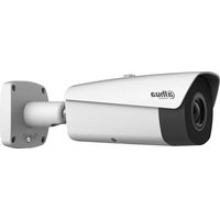
- Hybrid Thermal Camera
- Web Operation Manual
- Cybersecurity Recommendations
- Mandatory actions to be taken towards cybersecurity
- Change Passwords and Use Strong Passwords:
- Update Firmware
- Change Passwords Regularly
- Change Default HTTP and TCP Ports:
- Enable HTTPS/SSL:
- Enable IP Filter:
- Change ONVIF Password:
- Forward Only Ports You Need:
- Disable Auto-Login on SmartPSS:
- Use a Different Username and Password for SmartPSS:
- Limit Features of Guest Accounts:
- UPnP:
- SNMP:
- Multicast:
- Check the Log:
- Physically Lock Down the Device:
- Connect IP Cameras to the PoE Ports on the Back of an NVR:
- Isolate NVR and IP Camera Network
- FCC Information
- CAUTION
- FCC conditions:
- FCC compliance:
- General
- Models
- Safety Instructions
- Revision History
- Privacy Protection Notice
- About the Manual
- Table of Contents
- Cybersecurity Recommendations.... I
- Regulatory Information...... III
- Foreword IV
- Product Introduction.... 1
- Basic Settings....7
- Daily Operation.... 13
- Setting 47
- Peripheral 84
- Smart Thermal 86
- Event 105
- Temperature Measuring Settings....120
- Storage Management 127
- System Management....134
- System Maintenance.... 153
- Maintenance Requirements.... 153
- Auto Maintenance 153
- Backing Up and Restoring 154
- Upgrading Firmware 155
- Additional Accessing Methods....159
- Overview 1.1
- Features 1.2
- Functions 1.3
- Playback
- Report
- Alarm
- Account Management
- External Device Management
- Intelligent Thermal Imaging
- Event
- Temperature Measuring Settings
- Device Initialization 2.1
- Modifying IP Address 2.2
- Modifying One IP Address
- Modifying Several IP Addresses
- Preparation
- Procedure
- Logging in Web Interface 2.3
- Background Information
- Resetting Password 2.4
- Reset the password(1/2) Figure 2-7
- Reset the password. Step 3
- Click Next. Step 4
- Fill in a new password and confirm it. Step 5
- Click Save to finish password resetting. Step 6
- Live 3.1
- Introduction to Live Interface
- Function Bar
- Window Adjustment
- Image Adjustment
- Display of Smart Rules
- Zoom and Focus
- Optical Axis Calibration
- Real-time Reports
- More Functions
- Real-time Spot Temperature Measuring
- Laser Ranging
- PTZ 3.2
- Bullet Camera
- Configuring Protocol
- Configuring PTZ Functions
- Configuring Scan
- Configuring Presets
- Configuring Tour
- Configuring Pattern
- Turing on Wiper
- Operating PTZ
- Configuring Preset Backup
- Dome Camera
- Configuring Protocol
- Configuring PTZ Functions
- Configuring Preset
- Configuring Tour
- The tour interface Figure 3-16
- Configuring Scan
- The scan interface Figure 3-17
- Configuring Pattern
- The pattern interface Figure 3-18
- Configuring Pan
- Configuring PTZ Speed
- Configuring Idle Motion
- The idle motion interface Figure 3-21
- Configuring Power Up
- Configuring Time Task
- Restarting PTZ Manually
- Restoring PTZ to the Default Settings
- Operating PTZ
- Configuring Preset Backup
- Playback 3.3
- Video Playback
- Interface Layout
- Operate Control Bar
- Playing Back Videos
- Playing Back Videos in SD Card
- Step 4 Play video.
- Playing Back Local Videos
- Clipping Recorded Videos
- Picture Playback
- Interface Layout
- Picture Playback
- Reports 3.4
- Alarm 3.5
- Introduction to Alarm Types
- Subscribing Alarm Information
- Configuring Camera 4.1
- Configuring Lens
- Configuring Visible Image
- Configuring Picture Parameters
- Configuring Exposure
- Configuring Backlight
- Configuring White Balance
- Configuring Day & Night
- Configuring Focus & Zoom
- Configuring Defog
- Restoring Lens to the Default Settings
- Configuring Thermal Image
- Configuring Profile Management
- Configuring Video Parameters
- Configuring Video Streaming
- Configuring Image Streaming
- Configuring Video Overlay
- Configuring Privacy Masking
- Configuring Channel Title
- Configuring Time Title
- Configuring OSD Info
- Configuring Font
- Configuring Picture Overlay
- Configuring ROI
- Configuring Storage Path
- Configuring Audio Parameters
- Configuring Network 4.2
- Configuring TCP/IP
- Configuring Port
- Configuring Port Parameters
- Configuring ONVIF Verification When Logging
- Configuring PPPoE
- Configuring DDNS
- Configuring SMTP
- Configuring UPnP
- Configuring SNMP
- Configuring Bonjour
- Configuring Multicast
- Configuring Auto Registration
- Configuring 802.1X
- Configuring QoS
- Peripheral 4.3
- Configuring IR Light
- Step 1 Select Setting > Peripheral > IR Light.
- Configuring Wiper
- Step 1 Select Setting > Peripheral > Wiper.
- Configuring Fan
- Configuring Heater
- Smart Thermal 4.4
- Configuring Smart Plan
- Configuring IVS
- Basic Scene-Selecting Requirements
- Configuring Intelligent Rules
- Configuring Tripwire
- Configuring Intrusion
- Configuring Abandoned Object
- Configuring Missing Object
- Missing object Figure 4-46
- Configuring Global Setup
- Configuring Fire Warning
- Configuring Hot Trace
- Configuring Pic in Pic
- Configuring Link Schedule
- Event 4.5
- Configuring Video Detection
- Configuring Motion Detection
- Configuring Video Temper
- Configuring Audio Detection
- Configuring Temperature Alarm
- Configuring Alarm
- Configuring Abnormality
- Configuring SD Card Abnormality Parameters
- Configuring Network Abnormality Parameters
- Configuring Illegal Access Parameters
- Configuring Lenses Anti-Burning
- Temperature Measuring Settings
- Configuring Rules
- Configuring Temperature Measuring Rules
- Configuring Temperature Contrast
- Configuring Global Setup
- Exporting Heat Map
- Storage Management 4.7
- Configuring Schedule
- Configuring Video Recording
- Configuring Snapshot
- Configuring Holiday Schedule
- Device Storage
- Configuring Storage Path
- Configuring Local Storage
- Configuring FTP Server
- Configuring NAS Server
- Configuring Record Control Parameters
- System Management 4.8
- General Settings
- Configuring General Information
- Configuring Date & Time
- Configuring GPS
- User Management
- Adding a Group
- User group Figure 4-86
- Adding a User
- Modifying User Password
- Adding ONVIF User
- Safety Management
- Configuring RTSP Authentication
- Configuring IP Filter
- Configuring System Service
- Configuring HTTPS
- Creating and Installing Customized Certificates
- Certificate Figure 4-101
- 2) Click Install Certificate.
- 3) Click Next.
- Security warning Figure 4-105
- 7) Click Yes.
- Successful import prompt Figure 4-106
- 8) Click OK to finish installation of root certificate.
- Installing Signed Certificate
- Certificate Figure 4-108
- Security warning Figure 4-112
- Maintenance Requirements 5.1
- Auto Maintenance 5.2
- Rebooting Device
- Deleting Old Files
- Backing Up and Restoring
- Importing and Exporting
- Default Settings
- Upgrading Firmware 5.4
- Version Information 5.5
- System Log 5.6
- Searching System Logs
- Remote View
- Online User 5.7
- Accessing through NVR 6.1
- Accessing through SmartPSS 6.2
Brand : Dahua Technology
Model : DH-TPC-DF1241N-D
Category : Camera