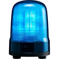
SF10-M1JN-B - Light signaling PATLITE - Free user manual and instructions
Find the device manual for free SF10-M1JN-B PATLITE in PDF.


| Product Type | Multi-function LED Signal Light |
| Model | SF10-M1JN-B |
| Power Supply | 12-24 V DC (M1 type) |
| Mounting | 3-screw or 2-point hole type mounting |
| Mounting Bracket | Included (with waterproof sheet, nuts, washers) |
| Recommended Wire Gauge | AWG28-14 (0.13-1.5 mm²) for terminal block |
| Wire Type | UL1007/UL1430, temperature rating above 75°C |
| External Contact Capacity | 3 A or more (M1) / 1 A or more (M2) for power supply |
| Buzzer (optional) | Available in SKH model, sound pressure may drop if opening is wet |
| Protection Rating | IP rating not specified; avoid water ingress at cable ends |
| Cleaning | Use soft cloth with water; do not use solvents, thinners, or oil |
| Safety Precautions | Disconnect power before repair; use fuse in wiring circuit |
| Compliance | EMC Directive (EN61000-6-4, EN61000-6-2), RoHS, FCC Part 15 Class A |
| Mounting Surface Thickness | Max board thickness not specified; use appropriate screws |
| Screw Hole Depth | 5.7 mm (M5 nominal diameter) for SF10 |
| Accessories Included | Mounting bracket, waterproof sheet, M5 nut, plain washer (3 each) |
Frequently Asked Questions - SF10-M1JN-B PATLITE
User questions about SF10-M1JN-B PATLITE
0 question about this device. Answer the ones you know or ask your own.
Ask a new question about this device
Download the instructions for your Light signaling in PDF format for free! Find your manual SF10-M1JN-B - PATLITE and take your electronic device back in hand. On this page are published all the documents necessary for the use of your device. SF10-M1JN-B by PATLITE.
USER MANUAL SF10-M1JN-B PATLITE
Multi-function Beacons
TYPE SF08 / SF10
Flashing Beacons
TYPE SL08 / SL10 / SL15
Notice to Customer
Thank you very much for purchasing our Patlite products.
- Request the installation and wiring be performed by a professional contractor if construction work is involved.
- Prior to installation, read this manual thoroughly before using this
product to ensure correct use. • In addition, please store this manual for future reference when
performing maintenance, repairs or inspections
- For options and repair parts, please visit our website (https://www.natlite.com)
(https://www.patite.com). - If there are any questions concerning this product, refer to the contact
information at the end of this document and contact your nearest BATUTE Sales Representative
PATLITE Sales Representative.
1 Read this First (Safety Precautions)
Warning Failure to observe the following may result in
Warning death or serious injury.
- To prevent from short-circuits or damage, observe the following: - Be sure the power is disconnected before replacement or repair
replacement of the fuse. Use this product in a property maintained condition. (Denise company if the
- Use this product in a properly maintained condition. (Replace of repair if the globe, case, etc. are damaged.)
- If installing this product requires construction work, ask a specialist in order to avoid fire or personal injury.
- avoid fire, or personal injury. - When this product is used for security purposes, it should be inspected daily.
In case a malfunction should occur, it is recommended that you use this product together with other security products.
- After installation, do not use this product to climb up onto the equipment with.
Failure to comply will result in product damage and/or falling off the machinery.
Caution Failure to comply with the following points may
A Caution result in injury, physical loss or damage.
- Be sure to put a fuse in the wiring circuit between the power source and equipment for protection. If a fuse is not added, it may result in product and/or
equipment not protection in a face is not necessary, if may result in product end-of equipment failure.
- Be sure to prevent electrostatic damage due to discharge when working with this product for wiring, exchanging units, setting up parameters, etc. by
this product for wiring, exchanging units, setting up parameters, etc. by discharging static electricity on your body, etc.
- Do not disassemble or detach during operation.
2 Model Number Configuration
■ SF·SL Models

RT 2-point Hole Type Mounting • Terminal block 3-point Hole Type Mounting • Terminal block (SL15 only)
(No text)
* KT only(SL15 : No Buzzer)
Model Number Example SF08-M1KTB-R
- ∅80 - 12 - 24 V DC - 2-point hole type mounting • Terminal block
■ SK Model
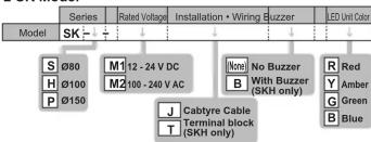
Model Number Example
SKH-M1JB-R
- ∅100 - 12 - 24 V DC - Cabtyre Cable - With buzze - Red color
5--7--8--6
3 Part Names
■ Cable type J
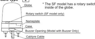
Front view Terminal bl


Accessory List
| NameModel | QTY | |
| SF□□-□□KT/SL□□-□□KT | Mounting Bracket, Waterproof Sheet | 1 |
| SF08-□□J/SL08-□□J/SKS Model | M4 Nut, Plain Washer | 3 |
| SF10-□□J/SL10-□□J/SKH Model | M5 Nut, Plain Washer | 3 |
| SL15-□□J/SKP Model | M8 Nut, Plain Washer | 3 |
4 Installation

■ 3-Screw Mounting Type J T
(1) Insert the bolts of the beacon into
the holes of the mounting surface.
(2) Use the nuts and washer
(accessory) to secure in place.
Installation Example

Maximum Board Thickness of Mountin

Installation Dimensions
Refer to the "Installation Manual"

■ 2-point Hole Type Mounting (SF • SL Models)
3-point Hole Type Mounting (SL15 Model Only)
(1) Use the screws or bolts, nuts. to secure the mounting bracket
(accessory) to the mounting surface. (Installation screws and nuts are not included with this product
(Installation screws and nuts are not included with this product. Binding head screws or pan head screws are recommended.)
| Model | Screw Hole Depth of Mounting Bracket | Nominal Diameter |
| SF08/SL08 | 4.4 mm | M4 |
| SF10/SL10 | 5.7 mm | M5 |
| SL15 | 4.8 mm | M8 |
(2) Check that the O-ring is not twisted.
(3) Align the main unit of product with the positioning Indicator and turn it clockwise to lock it.
Installation Example
2-point Hole Type Mounting 3-point Hole Type Mounting

Installation Dimensions
Defects the "Installation Manual"
Refer to the Installation Manual.
Caution Use a soft cloth moistened with water to clean the globe or soap. (Do not use thinner, boiling, saline or oil)
case. (Do not use trimmer, benzine, gasoline or oil.)
Note • The type with a buzzer, if the buzzer opening is splashed
with water, the Sound Pressure Level may drop.
5 Wiring
Caution • Make sure the power is OFF before wiring. A short circuit
■ Edition may damage internal circuits.
- Ensure the proper working voltage is used. Any mistake in wiring may result in damage
- Do not pull the wire, or stuff it inside of this case.
- Be sure the wiring is done properly. Any mistake in wiring may result in damage
- In the M2 model, do not perform blinking control by turning the power supply ON / OFF. Any mistake in wiring may result in damage.
- Do not apply a voltage to the common wire. (M1 type)
Do not apply a voltage to any wire other than the power supply wire. (M2 type)
Failure to comply will result in product damage.(except buzzer wire of SKH-M1) Do not expose the wiring from the device. If tension is applied to the wiring, the
- Do not expose the wiring from the device. If tension is applied to the wiring, the wiring may be disconnected, resulting in a short circuit or an electric shock.
- Use either a Contact Switch or Contact Relay for External Contact that power
supply wire of SF, SL, SK Models and buzzer wire of SK Model. Failure comply may result in fire, product malfunction.
Notice • The protection rating does not include the Cabtyre Cable
Ends. If the ends of the it are in contact with water so exposed to dry water
In the ends of the it are in contact with water or exposed to dew or condensation, refer to the indications below to dress the wire and
condensation, refer to the indications below to dress the wire ends for water resistance.
- Connect the it ends in a location which will not expose the ends to water.
- Use Fillers, such as silicon, etc., to seal the it ends.

[ External contact capacity of power supply wire ]
M1 M2
Current Capacity (Is) 3A or more 1A or more
[ External contact capacity of signal wire and buzzer wire ]
[External contact SE • SI . Models
| M1 | M2 | |
| Current Capacity (Is) | 10 mA or more | 10 mA or more |
| Withstand Voltage (Vs) | 20 V or more | 20 V or more |
| Leakage Current • (IL) | 0.1 mA or less | 0.1 mA or less |
- When using an NPN open-collector transistor.
SK Model
M1 M2
| Current Capacity (Is) | 0.5 A or more | 0.5 A or more |
| Withstand Voltage (Vs) | 35 V or more | 20 V or more |
[ Fuse ]
Fuse Rating 250 V 1 A
Wire Type / Wire Gauge
Wire Type : UL2464
Wire Gauge : M1 AWG22
M2 Power Supply Wind
M2 Power Supply Wire AWG18 Excluding Power Supply Wire AWG24
Wiring Example
Refer to the "Installation Manual".
Terminal Block Wiring
■ Recommended lead wire specifications
Wire Type Wire Gauge (Solid Wire) Wire Gauge (Stranded Wire)
Wire Type Wire Gauge (Solid Wire) Wire Gauge (Stranded Wire) UI 1007 / UI 1430 0.13 \~ 1.5 mm 2 AWG28 \~ 14
Temperature reading should be above 75°0 and the conductivity material should
• Temperature rating should be above 75°C, and the conductor material should be of copper wire.
Note
Note
Strip 8-9 mm of wire insulation from the lead wire to insert into the terminal block. Do not run on to the lead wire to campus, always unlock the lever before
Do not tug on to the lead wire to remove- always unlock the lever before removing the wires.
The tip of the flathead screwdriver should be no more than 2mm wide and
0.5 mm thick
- Do not put excessive force on the lever, as this may cause the lever to break.
■ Installation
to the press
to the groove of
ase the lock.


6 Specifications

• EMC Directive (EN61000-6-4, EN61000-6-2)
• ROHS Directive (EN5058) • UL 508, CSA-C22 2 No 14
• FCC Part 15 Subpart B Class A
This product conforms to EN standards and shows the CE Marking. This product has been tested and found to comply with the limits for a Close A
This product has been tested and found to comply with the limits for a Class A device, pursuant to EMC DIRECTIVE. These limits are designed to provide
reasonable protection against harmful interference when the equipment is operated in
a commercial environment. This product must not be used in residential areas.
This equipment has been tested and found to comply with the limits for a Class A digital device, pursuant to Part 15 of the FCC Rules. These limits are designed to
provide reasonable protection against harmful interference when the equipment is
operated in a commercial environment. The equipment generates, uses, and can radiate radio frequency energy and, if not installed and used in accordance with
radiate radio frequency energy and, if not installed and used in accordance with the instruction manual, may cause harmful interference to radio communications
Operation of this equipment in aresidential area is likely to cause harmful
interference in which case the user will be required to correct the interference at
his own expense
(Note) • Dimensions and specifications may change without notice due to
continual product improvement
- PATLITE and the PATLITE logo is a trademark, or registered trademark of the PATLITE Corporation of Japan and each country.
the PATENTE Corporation of Japan and each country.
(Importer for EU)
PATLITE Europe GmbH Am Soeldnermoos 8, D-85399 Hallbergmoos, Germany
- NOTICE TO CUSTOMER
- 1 READ THIS FIRST (SAFETY PRECAUTIONS)
- WARNING FAILURE TO OBSERVE THE FOLLOWING MAY RESULT IN
- CAUTION FAILURE TO COMPLY WITH THE FOLLOWING POINTS MAY
- 2 MODEL NUMBER CONFIGURATION
- SF·SL MODELS
- (NO TEXT)
- SK MODEL
- MODEL NUMBER EXAMPLE
- 3 PART NAMES
- CABLE TYPE J
- FRONT VIEW TERMINAL BL
- ACCESSORY LIST
- 4 INSTALLATION
- 3-SCREW MOUNTING TYPE J T
- MAXIMUM BOARD THICKNESS OF MOUNTIN
- INSTALLATION DIMENSIONS
- 2-POINT HOLE TYPE MOUNTING (SF • SL MODELS)
- INSTALLATION EXAMPLE
- 5 WIRING
- WIRE TYPE / WIRE GAUGE
- WIRING EXAMPLE
- TERMINAL BLOCK WIRING
- 6 SPECIFICATIONS
Brand : PATLITE
Model : SF10-M1JN-B
Category : Light signaling