SA-20 - Power Strip SurgeX - Free user manual and instructions
Find the device manual for free SA-20 SurgeX in PDF.

| Product Type | Power Strip |
| Brand | SurgeX |
| Model | SA-20 |
| Number of Outlets | 20 |
| Surge Protection Rating | 5080 Joules |
| Voltage | 120V / 60 Hz |
| Maximum Current | 20 A |
| Cord Length | 10 ft (3.05 m) |
| Dimensions (L×W×H) | 19 × 3.5 × 2.5 in (48.3 × 8.9 × 6.4 cm) |
| Weight | 4.2 lb (1.9 kg) |
| LED Indicators | Power, Protected, Ground |
| Reset Function | Circuit breaker reset |
| Safety Certifications | UL 1449 |
| Warranty | 5 years limited |
| Cleaning Instructions | Unplug and wipe with dry cloth |
| Spare Parts Availability | Contact SurgeX support |
Frequently Asked Questions - SA-20 SurgeX
User questions about SA-20 SurgeX
0 question about this device. Answer the ones you know or ask your own.
Ask a new question about this device
Download the instructions for your Power Strip in PDF format for free! Find your manual SA-20 - SurgeX and take your electronic device back in hand. On this page are published all the documents necessary for the use of your device. SA-20 by SurgeX.
USER MANUAL SA-20 SurgeX
Axess-Ready Standalone Surge Elimination & Power Conditioning

natural_image
Exterior view of a black SURGEX medical device with two yellow buttons and a small connector (no visible text or symbols on the device body)SA-20-AR
Firmware Version: 1.20.261
Software Version: 2.00.03
I. INTRODUCTION 2
II. INSTALLATION 4
- PHYSICAL 4
- ETHERNET CONNECTION 4
- AC POWER CONNECTIONS ....4
III. LED INDICATORS 4
IV. INITIAL SET-UP 5
DEVICE MANAGEMENT UTILITY (DMU)....5
SETTING THE IP ADDRESS 6
V. WEB SERVER 8
PASSWORD 8
CONTROL AND STATUS PAGE 8
SETUP PAGES....9
■ DEVICE....9
■ NETWORK 10
■ Advanced Network....11
- AUTOPING....12
- SCHEDULE....14
- PASSWORDS....15
VI. COMMAND LINE INTERFACE (CLI) PROTOCOL 16
OVERVIEW....16
PROMPTS....16
CONTROL COMMANDS....16
DEVICE COMMANDS 16
NETWORK COMMANDS 17
AUTOPING COMMANDS 18
USER COMMANDS 18
EVENT COMMANDS....19
VII. DXP PROTOCOL 20
OVERVIEW....20
HELLO HANDSHAKE....20
DxP PACKET 21
COMMANDS....22
DESCRIPTORS 22
PAYLOADS....24
VIII. FIRMWARE UPGRADES 25
IX. RESET BUTTON 25
X. SPECIFICATIONS 26
I. INTRODUCTION
The SurgeX® SA-20-AR is a network attached, IP addressed, web-controlled AC surge eliminator and power conditioner. The SA-20-AR may be used to switch up to 20A at 120V. The simple web server structure allows basic control of two outlets. The extensive programming and setup capabilities are accessed by a web browser, through a Device Management Utility (DMU), or through a Command Line Interface (CLI).
- The SA-20-AR features SurgeX ^® Advanced Series Mode ^® surge elimination and Impedance Tolerant EMI/RFI filtering.
- Remote reboot any device: monitors, routers, servers, kiosks, etc. The remote device need not be network attached.
- Conserve energy by powering down equipment when not in use.
- Telnet access uses the Command Line Interface (CLI) structure and syntax to completely configure and control the SA-20-AR. This Axess Ready (AR) device also supports the DxP protocol, which allows software developers to integrate the unit into custom applications.
- Up to 2 systems can be continuously monitored with AutoPing, with automatic power control upon loss of contact. Reboot crashed systems, or provide auto power-up or -down for environmental controls and notification systems.
- The SA-20-AR utilizes 2 levels of password security, with only the administrative account having access to setup and configuration.
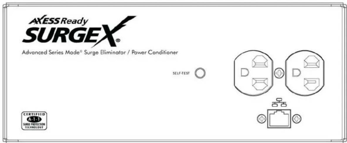

Located on the top panel are:
• Network connection (RJ-45)
- Output receptacles
- Self-Test LED
Located on the side panels are:
- Input power plug: NEMA 5-20
- Reset button
- System On LED
II. INSTALLATION
1. Physical
Stand Alone (SA) products are designed to rest on a flat surface or to be mounted onto a flat surface, such as a wall. To mount the SA product, use six 6-32 Phillips pan head screws (included) to attach the removable mounting brackets (included) to the sides of the product.
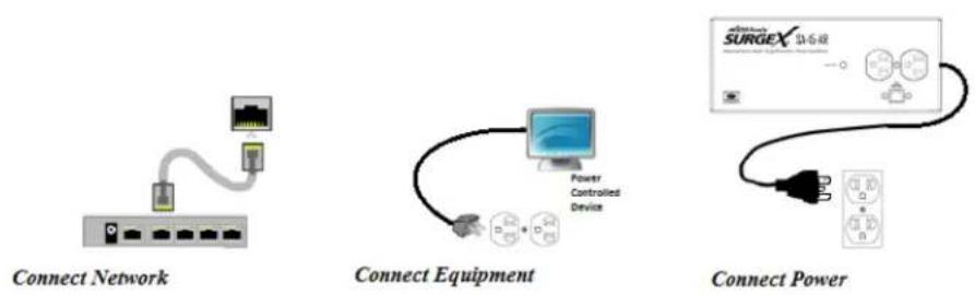
2. Ethernet Connection
The RJ45 connector for 10/100 Ethernet is situated on the top panel beside the output receptacles. The default IP Address is DHCP assigned. The fallback IP address is 192.168.1.254.
3. AC Power Connections
Connect the device(s) to be powered On and Off to the output duplex receptacle.
Ensure that the total combined load of all controlled devices does not exceed 20 Amps.
Connect the attached power cord to a properly grounded 120VAC outlet. SA-20-AR models require a NEMA 5-20R outlet. Do not plug the unit into a re-locatable power tap.
III. LED INDICATORS
| SYSTEM ON | The Axess Ready system is On, and the outlets are On. | |
| SELF-TEST | The internal surge protection circuitry is fully functional. |
IV. INITIAL SET-UP
Device Management Utility (DMU)
The SurgeX Device Management Utility (DMU) provides the easiest means to find and configure your AR for use. The DMU can:
- Automatically discover multiple ARs on a local network.
- Display the current IP address of each AR.
- Allow the setting of a new IP address for each AR.
- Perform firmware upgrades.
- Return an AR to Factory Defaults.
The SurgeX Device Management Utility is available on the SurgeX website at http://www.surgex.com
Note: The IP address can only be set within the first 2 minutes after powering up the AR. The utility will only work with ARs on the same local subnet as the PC.
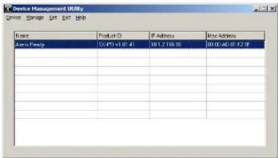
DMU automatically discovers devices on the local network
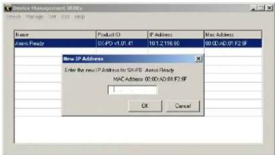
Enter new IP address for selected SX-iPD.
- Device
○ Discover: Automatically discover all ARs on the local network. The DMU will display the location name of the AR, the product ID and version number, the current IP address, and the MAC address. Factory defaulted ARs will display with the name Axess Ready and have an IP address that was automatically assigned by the DHCP server on your network.

IP address successfully set
- The IP address field also indicates the port for web access that is currently in use by the AR. The standard port for web browser accessibility is factory default Port 80.
○ Add: Manually add an AR by IP address.
- Clear: Clear the list.
- Manage
-
Open Browser: Opens the web browser interface for the selected AR.
○ Upgrade Firmware: Starts the Firmware Upgrade dialogue. Firmware Upgrade requirements: -
Valid firmware file.
- Administrative login credentials.
- “Upgrade Enable” must be set to yes, set via web page or CLI.
- Set
- IP Address: Changes the IP address of the selected AR.
○ Factory Defaults: Return the selected AR to a Factory Default state. This action must be performed within the first 2 minutes after powering up the unit.
○ Local Address: Select the IP address to Discover on. This may be necessary for computers with multiple network connections.
- Exit
○ Exits the DMU program.
• Help
○ Online Help: Opens a web browser to online help resources.
○ About: Displays DMU version information.
Setting the IP Address
ARs are configured with a DHCP assigned factory default IP address.
To set the AR's IP address using one of the following methods, the computer and AR must be on the same local network.
- DMU: Follow the steps in the preceding subsection to set the IP address using the Device Management Utility (DMU).
○ CLI: These are the basic commands to set the network parameters. After setting these parameters, the AR will need to be rebooted for the settings to take effect. Any command that requires rebooting of the AR will provide a prompt to do so. All commands may be entered as required before rebooting. Manually specifying the IP address via CLI automatically sets the address as static.
Example: Telnet to default IP address of 192.168.1.254 on default Port 23:
SurgeX Axess Ready v1.01.41
User> admin
Password> *****
Axess Ready> set ipaddress 10.1.2.69
Ok
Axess Ready Reboot Required> set subnet 255.255.255.0
Ok
Axess Ready Reboot Required> set gateway 10.1.2.1
Ok
Axess Ready Reboot Required> reboot
The CLI command set ipmode dhcp followed by a reboot command may be used to configure the AR to automatically acquire its network settings from a DHCP server. A DHCP server will automatically assign an IP address (dynamic address), as well as the Subnet Mask and Gateway.
To determine what IP address has been automatically assigned by the DHCP server, you will need to use the Discover feature of the DMU or query your DHCP server and locate the MAC address of the AR in the DHCP server's IP/MAC table.
Web: To set the IP address using a web browser, navigate to the current IP address of the AR. Enter the administrator credentials (Factory Default User: admin, Password: admin), click on "Setup", then click on "Network" and follow the directions in the Web Server/Network/Setup section of this manual.
V. WEB SERVER
The Axess Ready web interface provides the easiest means of operating the outlet and changing configuration parameters.
To access the web interface, open a web browser and enter the IP address of the AR into the address bar.
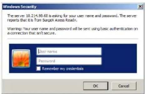
Password
The AR uses two username/password credential sets, one for normal power control (user) and one that also provides access to the Setup functions (admin).
Default credentials:
| Role | Username (fixed) | Password (user set) |
| Administrator | admin | admin |
| User | user | user |
Enter a valid username and password when prompted. When the proper username/password combination is received, the Control and Status Page is displayed.
Control and Status Page
Once a user is validated, the Control and Status page is displayed.
Note: Only one user may be logged in to the AR at a time.
Press “Power On” or “Power Off” to turn the AC output On or Off. In the event of a power outage, the AC output will return to its last known state prior to the outage.

Press “Cycle Power” to temporarily change the state of the AC output for a specified cycle time (factory default is 10 seconds). The cycle operation performed will either be On-Off-On or Off-On-Off, depending on the initial state of the AC output. During the power cycle operation, the Power Status bar will indicate the temporary status with a Blue background. Once the cycle is complete, the status bar will revert to its original condition. To abort a power cycle, press either “Power On” or “Power Off” and the outlets will assume that status.
Use the Refresh button to update the page with the most current status. Use of the browser's refresh button may lead to inadvertent power switching. If an NTP time server is being used, the time of the last refresh will be displayed in the upper right corner, as well as a History log below the Power Status.
Setup Pages
Setup pages are only available while logged in with Administrator credentials. Press Save to save the new settings. If the new settings require the AR to be rebooted, a Reboot button will appear at the bottom of the page. Settings requiring reboot will not take effect until the unit is rebooted.
○ Device
- Location ID: Specifies a name label (up to 20 characters) that will be displayed at the top of all pages. Assigning unique names is helpful for management of multiple units.
- Cycle Time: Specifies the length in seconds of a power cycle (1-999 seconds). This is the amount of time the outlet will temporarily be On or Off, depending on the initial outlet state.
- Disable Off: When checked, removes the Power OFF button from the Status and Control page.
- Upgrade Enable: Enables the ability to upgrade the firmware of the AR.
- Auto Logout: Specifies the inactivity timer duration in minutes (0-99 minutes). If there is no activity after the specified amount of time, the user will be automatically logged out. Setting the timer duration to 0 disables the timeout feature.
- Enable Security Timeout: When unchecked, disables the 2-minute window for setting IP address and factory defaults via DMU.
Important: As the AR allows only one web user logged in at any time, use caution when disabling the timeout feature, as it is possible to lock out other users by forgetting to log out. Closing the web browser will not log the user out and may lock out web access. In this situation it will be necessary to access the AR via telnet and reboot the unit.

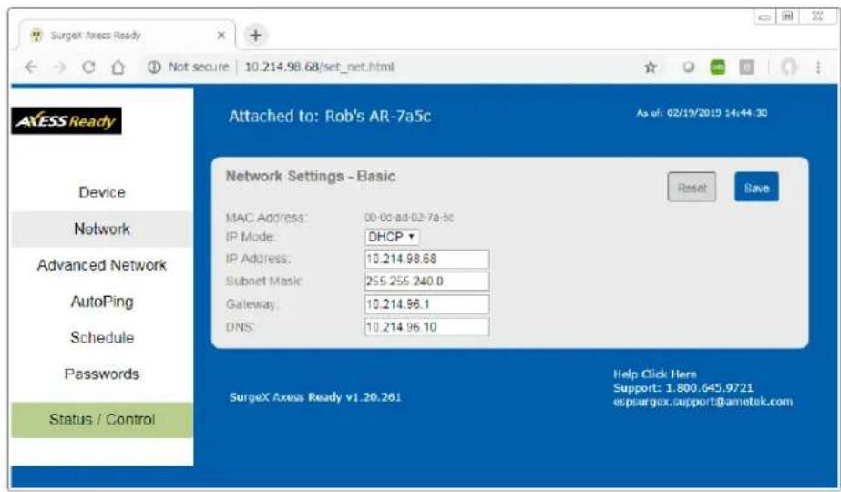
Network
- IP Mode: Select Static to manually set the IP address using the fields below or choose DHCP to allow the AR to automatically acquire its network settings from a DHCP server.
- IP Address: Enter a static IP address in dotted decimal format. This field will be automatically set if using DHCP.
- Subnet Mask: Enter the Subnet Mask in dotted decimal format. This field will be automatically set if using DHCP.
- Gateway: Enter the Gateway in dotted decimal format. This field will be automatically set if using DHCP.
- DNS: Enter the Domain Name Server address. This will be automatically set if using DHCP.
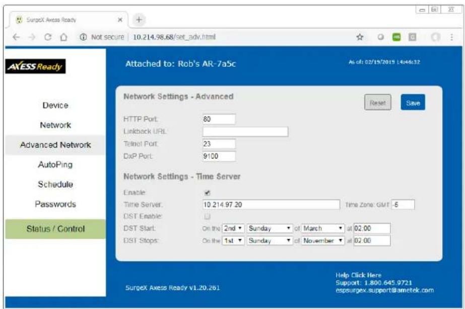
- Advanced Network
- HTTP Port: Specify the port the web server will be accessed on. If the port is changed from the default value of 80, the AR may be accessed by specifying the new port number in this format: http://IPADDRESS:NEWPORT. Example:
Navigate to http://192.168.1.254:8000 for an IP address of 192.168.1.254 on port 8000.
- Linkback URL: This setting allows control of the hotlink displayed on the Goodbye page. It allows use of the public IP address or DNS name instead of the internal IP address of the AR, which is the default setting. If this setting is left blank, the hotlink will be the IP address of the unit. Enter up to 128 characters.
- Telnet Port: Specify the port to use for telnet access (default 23). DxP Port: Specify the port to use for DxP protocol (default 9100).
- Time Setup: Setup of the time server is required for Scheduling and Logging functions.
○ Enable: Enable or disable the use of the time server.
○ Time Server: Specify the time server. The default is time.nist.gov.
○ Time Zone: Specify the time zone (-12 to +12) relative to GMT.
o DST Enable: Enable or disable the use of Daylight Savings Time.
o DST Start/Stop: Specify the start and stop times for DST.
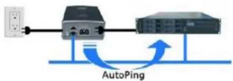
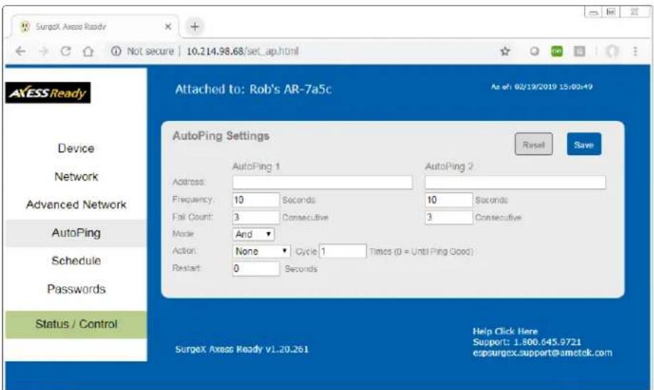
○ AutoPing
The AutoPing feature allows the AR to automatically detect failed equipment and perform a timed reboot or other power control function (like turning on an indicator or siren). First specify one or two IP addresses to be periodically pinged. When the AR no longer receives a response from these addresses, the programmed power control function is actuated. AND or OR logic can be applied to the two addresses, so that both (AND) or either (OR) must fail in order to trigger the selected action.
Examples:
Server monitor: AR is installed with the device it monitors and automatically reboots if there is no response. Ideal for Kiosks and Servers.
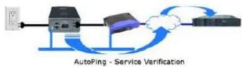
Service monitor: AR is installed with the device to be rebooted but pings a remote host to test the communication channel. Ideal for DSL/Cable Modem verification.
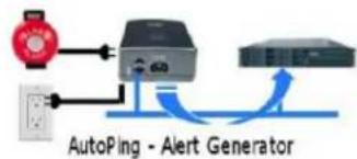
AR monitors a network device and powers up an alarm or redundant system when there is no response. Ideal for Hot Standby Servers, Environmental Control, Alert for any network failure.
flowchart
graph LR
    A["Power Input"] --> B["Switch"]
    B --> C["Server"]
    C --> D["AutoPing"]
    D --> B
flowchart
graph LR
    A["Power"] --> B["Server"]
    B --> C["Network"]
    C --> D["Server"]
    style A fill:#f9f,stroke:#333
    style D fill:#bbf,stroke:#333
    note bottom of B "AutoPing - Service Verification"
flowchart
graph TD
    A["Sensor"] --> B["Alert Generator"]
    C["Ground"] --> B
    B --> D["Output"]
- IP Address 1 and 2: Enter the IP address(es) of the device(s) to be pinged.
- Frequency 1 and 2: Enter the desired ping frequency in seconds for the device(s) to be pinged (1-999 seconds).
- Fail Count 1 and 2: Enter the number of times the ping must consecutively fail (1-999) before the selected action is triggered.
- Mode: Select the logic to be used (AND, OR, or Single). With AND logic, both AutoPings must exceed their fail count to trigger the action. With OR logic, the action will be triggered if either AutoPing exceeds its fail count. With Single, only AutoPing 1 is used.
• Action: Select the action to be triggered.
| None | AutoPing not used |
| Power On – Latch | Upon triggering, AR will power on and remain so until changed via web, telnet, or DxP. |
| Power On – Follow | Upon triggering, AR will power on. When the ping response returns, AR will power off. |
| Power Off – Latch | Upon triggering, AR will power off and remain so until changed via web, telnet, or DxP. |
| Power Off – Follow | Upon triggering, AR will power off. When the ping response returns, AR will power on. |
| Power Cycle | Upon triggering, AR will cycle the power. AR will then wait for (Ping Frequency x Fail Count) seconds; if the response does not return, the power will be cycled again. This will repeatedly continue until the ping response returns or AutoPing is turned off. Ensure that the AutoPing frequency is longer than the time required to reboot the device. |
| Power Cycle - Once | Upon triggering, AR will cycle power one time. It will not cycle again automatically until the ping response returns and is lost again. |
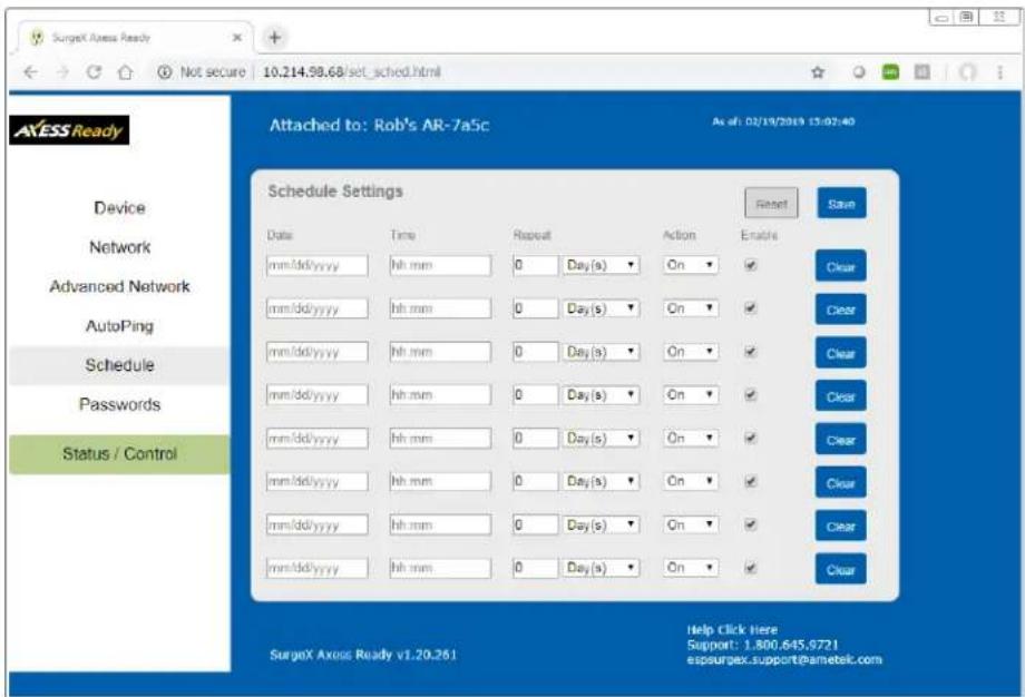
○ Schedule
The AR can schedule up to 8 recurring power events. For each event, you may define the starting date and time, the action to be taken, and the repetition interval (optional).
Important: A Network Time Server (NTS) must be specified and enabled in order to use the time scheduling feature. A list of public time servers is available at http://www.ntp.org.
- Date: Set the initial date for the event in mm/dd/yyyy format.
- Time: Set the initial time for the event in hh:mm format. Hours are specified in 24-hour format; for example, 8:05 pm would be entered as 20:05.
- Repeat (Optional): Set the repetition interval. 0-999 Days, Hours, or Minutes.
• Action: Set the action to be scheduled. On, Off, or Cycle.
- Enable: Enables the event when checked. Uncheck to disable the event.
- Clear: Deletes a schedule.
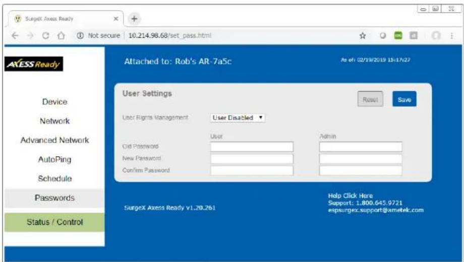
○ Passwords
Two passwords are used by the AR. The User password allows control of the AC output state but provides no access to Setup functions. The Administrator password allows full control and setup of the AR.
Passwords may be up to 20 characters long and are case sensitive.
The AR supports three modes of user and password operation.
- Login Required: Login with password is required for web and telnet access.
- Auto Login: No login challenge will be required for any mode of operation, until a Setup function is requested.
- User Disabled: There is no User account. The Admin username and password will be required for operation and setup functions across all modes of operation. This is the factory default mode.
- Old Password: Enter the password currently in use.
- New Password: Enter the new password to be used.
- Confirm Password: Enter the new password to be used again.
Default credentials:
| Role | Username (fixed) | Password (user set) |
| Administrator | admin | admin |
| User | user | user |
VI. COMMAND LINE INTERFACE (CLI) PROTOCOL
The Command Line Interface provides complete setup of all functions of the AR. The CLI may be accessed through the Telnet protocol, and requires a Telnet client program. Some commands of the CLI require administrative rights; these are indicated in the following tables.
Notes:
• Telnet negotiations require sending these bytes when first connecting: (0x) FF FD 01 FF FD 03 FF FB 1F FF FB 18 FF FB 20
• Every command must be followed by a Carriage Return and Line Feed: (0x) 0D 0A
| Prompt | Description |
| User> | Prompts the user to enter the user name (either user or admin). |
| Password> | Prompts the user to enter the password. |
| Axess Ready> | Prompt displayed while logged in. |
| Axess Ready Reboot Required> | Prompt displayed after changes have been made that require a reboot. This prompt will remain active until the AR has been rebooted. |
| Command | Description | Admin | Fact Def |
| get outlet | Returns the current status of the outlet. | No | |
| set outlet < on | off |cycle > | Sets the outlet to the selected state. | No |
| Command | Description | Admin | Fact Def |
| get location | Returns the location ID. | Yes | Axess Ready |
| set location < 20-character max > | Sets the location ID. | Yes | |
| get cycle | Returns the cycle time currently in use in seconds. | Yes | 10 |
| set cycle < 1-999 > | Sets the cycle time in seconds. | Yes | |
| get upgrade enable | Returns the upgrade enable status. | No | Disabled |
| set upgrade enable < yes | no > | Enables or disables the ability to upload new firmware. | Yes | |
| logout | Terminates the telnet session. | No | |
| reboot | Reboots the AR. | Yes |
Network Commands
| Command | Description | Admin | Fact Def |
| get network | Returns all network settings currently in use. Example:Mode: DHCPIP Address: 10.1.2.69Subset: 255.255.255.0Gateway: 10.1.2.1HTTP Port: 80Telnet Port: 23DxP Port: 9100Timeout: 20Ok | Yes | |
| set ipmode < static | dhcp > | Sets the IP address mode. Static mode locks the IP address as set; DHCP mode allows a DHCP server to assign the address. | Yes | Static |
| set ipaddress < dotted decimal > | Sets the IP address. | Yes | 192.168.1.254 |
| set subnet < dotted decimal > | Sets the Subnet Mask. | Yes | 255.255.255.0 |
| set gateway < dotted decimal > | Sets the Gateway address. | Yes | 192.168.1.1 |
| set http port < 0-65535 > | Sets the port that the internal Web server listens for incoming connections on. When set to 0 the web server is disabled. May not be disabled when Telnet and DxP are both disabled. | Yes | 80 |
| set telnet port < 0-65535 > | Sets the port that the internal Telnet server listens for incoming connections on. When set to 0 the Telnet server is disabled. May not be disabled when Web and DxP are both disabled. | Yes | 23 |
| set dxp port < 0-65535 > | Sets the port that the internal DxP service listens for incoming connections on. When set to 0 the DxP service is disabled. May not be disabled when Web and Telnet are both disabled. | Yes | 9100 |
| set timeout < 0-999 > | Sets the automatic network timeout in minutes. | Yes | 2 |
AutoPing Commands
| Command | Description | Admin | Fact Def |
| get autoping | Returns all AutoPing settings currently in use. Example:AutoPing 1 AutoPing 2IP Address: 10.1.2.36 0.0.0.0Frequency: 60 10Fail Count: 3 3Status: OK OKTrigger Count: 0 0Mode: SingleAction: On-LatchOk | Yes | |
| set autoping < 1 | 2 > ipaddress < dotted decimal > | Sets the IP address to be pinged for AutoPing 1 or 2. | Yes | 0.0.0.0 |
| set autoping < 1 | 2 > frequency < 1-999 > | Sets the frequency (how often the ping is sent) for AutoPing 1 or 2 in seconds. | Yes | 10 |
| set autoping < 1 | 2 > failcount < 1-999 > | Sets the number of consecutive failures the AutoPings must detect before the AutoPing considers the pinged device to be failed. | Yes | 3 |
| set autoping mode < single | and | or > | Sets single AutoPing (AutoPing 1) or two AutoPing relationship AND or OR. | Yes | AND |
| set autoping action < none | on-latch | on-follow | off-latch | off-follow | cycle | cycle-once > | Sets the action to be performed when the AutoPing is triggered. | Yes | None |
User Commands
| Command | Description | Admin | Fact Def |
| set password < user | admin > < old > < new > < repeat > | Sets the password of the User or Administrator. | Yes | user | admin |
Event Commands
| Command | Description | Admin | Fact Def |
| get events | Returns all scheduled events currently in use. Example:Date Time Repeats Action1. 12/22/2011 14:00 every 2 Hour(s) Cycle2. every 0 Day(s) On3. every 0 Day(s) On4. every 0 Day(s) On5. every 0 Day(s) On6. every 0 Day(s) On7. every 0 Day(s) On8. every 0 Day(s) OnOk | No | |
| get time | Returns the current time and time server. Example:Current Time: 10:14:17 12/20/2011Server: 10.1.2.12Ok | No | |
| set time server < dotted decimal > | Sets the IP address of a Network Time Server. | Yes | 64.90.182.55 |
| set time enable < yes | no > | Enables or disables the use of a time server and scheduled events. | Yes | No |
| set event < 1-8 > date < mm/dd/yyyy > | Sets the scheduled event's starting date. | Yes | |
| set event < 1-8 > time < hh:mm:ss > | Sets the time the scheduled event will occur in 24-hour format. | Yes | |
| set event < 1-8 > repeat < day | hour | minute > | Sets the repetition interval type for the selected event. | Yes | |
| set event < 1-8 > mult < 0-999 > | Sets the number of repetition intervals for the selected event. For example, 20 days, 30 minutes, 24 hours, etc. | Yes | |
| set event < 1-8 > action < on | off | cycle > | Sets the action to be performed at the scheduled time. | Yes | |
| del event < 1-8 > | Deletes the scheduled event. | Yes |
VII. DxP PROTOCOL
Overview
The DxP Protocol is a packet-based protocol designed to be extensible. This protocol is transmitted over TCP on a user-defined port. The factory default DxP port is 9100.
The protocol uses a Hello handshake to establish unique sequence numbers to allow for advanced security when AES encryption is used. With AES enabled, all messages must be encrypted with the AES Passphrase set in the device.
After the Hello, a Command and Response sequence follows. Any number of Command → Response sequences are permitted after Hello.
Hello Handshake
The client sends a Hello message in the form of a text string 'hello-000'. The DxP enabled device will respond with a packet containing the unsigned 16-bit sequence number. This sequence number is incremented by the client and server with each correct packet sent.
Example:
| Client | Server | |
| hello-000 | → | |
| ← | 1234 (seq 1234) | |
| Command (seq 1235) | → | |
| ← | Response | |
| Command (seq 1237) | → | |
| ← | Response |
DxP Packet
The packet is broken up into 2 parts: The Header and the Payload.
○ Header
The header is used to carry general information, such as is shown in the C programming structure below:
typedef struct { eCmnd command; char[21] uName; char[21] password; uChar desc; uChar param; uint16 seq; } THeader
| Variable | Description |
| command | Enumerated type that tells the DxP server what class of command is being sent. See the Commands subsection for a full list of command classes. |
| uName | Reserved for future use. It will contain the user name of a user on the ipIO that is being accessed. |
| password | Reserved for future use. It will contain the password of the user above. |
| desc | Command descriptor that describes the individual command within a command class. By extension it lets the server know what the payload is. There is a different set of descriptors for each command class; see the Descriptors subsection for a full list of descriptors by command class. |
| param | Reserved for future use. Optional parameter that may be passed to the server in addition to the descriptor. |
| seq | The packet's sequence number. Used as part of the security scheme. |
○ Payload
The payload is determined by a combination of the command class and the descriptor. The payloads are described with the descriptor; see the Descriptors subsection for details.
Commands
There are currently 7 command classes. All classes are defined in the C programming enumerated type definition below:
typedef enum {
    eCmnd_null,
    eCmnd_set,
    eCmnd_get,
    eCmnd_io,
    eCmnd_keepAlive,
    eCmnd_rss,
    eCmnd_rcu
} eCmnd;
| Command | Description | |
| 0 | eCmnd_null | This is a null command and should not be sent to the server. |
| 1 | eCmnd_set | This command is used to set programmable variables on the server. |
| 2 | eCmnd_get | This command is used to get programmable variables from the server. |
| 3 | eCmnd_io | This command is used to monitor and control the I/O on the server. |
| 4 | eCmnd_keepAlive | This command is sent to the server as a means of allowing the client to validate the communications path to the server. |
| 5 | eCmnd_rss | This command class is used to control the RSS nest using the RCU.Note: Project specific command. Not for general use. |
| 6 | eCmnd_rcu | This command class is used to update the display of the RCU.Note: Project specific command. Not for general use. |
Descriptors
Descriptors are used to describe the individual command within a command class, and the payload that the packet contains. All of the descriptors and their payloads are outlined by command class below.
o eCmnd set
The descriptors for this command class will be product specific.
o eCmnd_get
The descriptors for this command class will be product specific.
o eCmnd io
typedef enum {
    eIO_null,
    eIO_changeRelay,
    eIO_changeRelays,
    eIO_getRelay,
    eIO_getRelays,
    eIO_getInput,
    eIO_getInputs,
    eIO_pulseRelay,
} eIO;
| Command | Description | Server Response |
| eIO_changeRelay | This command is used to change the status of an individual relay. It carries the TChangeRelay payload; see the Payloads subsection for details. | 0 → Successful1 → Error |
| eIO_changeRelays | This command is used to set all of the relays in a device. It carries the TChangeRelays payload; see the Payloads subsection for details. | 0 → Successful1 → Error |
| eIO_getRelay | This command has not yet been implemented. | |
| eIO_getRelays | This command is used to get the status of all the relays on the server. | Byte Array containing status of each relay. |
| eIO_getInput | This command has not yet been implemented. | |
| eIO_getInputs | This command is used to get the status of all inputs on the server. | Byte Array containing status of each input. |
| eIO_pulseRelay | This command is used to pulse a relay. It carries the TPulseRelay payload; see the Payloads subsection for details. | 0 → Successful1 → Error |
o eCmnd_keepAlive
typedef enum {
eKeepAlive_null;
} eKeepAlive;
| Command | Description | Server Response |
| eKeepAlive_null | This is the only valid descriptor that the keep alive command supports. It is defined as null, as it carries no payload. | 0 → Successful1 → Error |
Payloads
○ TChangeRelay
typedef struct {
    unsigned char relay;
    unsigned char state;
} TChangeRelay;
Where relay is the number of the relay to be affected - 1 (For example, 0 for relay 1 and 1 for relay 2) and state sets the state of the relay (1=Energize; 2=Relax).
○ TChangeRelays
typedef struct {
    unsigned char relayStates[32];
} TChangeRelays;
Where relayStates is an array of relay states as defined below:
#define NO_CHANGE 0
#define ENERGIZE 1
#define RELAX 2
This payload is supported by devices that support the DxP protocol with 2-32 controllable relays.
○ TPulseRelay
typedef struct {
    unsigned char relay; // the relay to be pulsed
    unsigned char state; // the state to pulse
    uint16 pulseWidth; // the pulse width in seconds
} TPulseRelay;
Where relay is the number of the relay to be affected, state is the state to pulse, and pulseWidth is the time to pulse in seconds.
VIII. FIRMWARE UPGRADES
The AR can be upgraded via the network if the upgrade feature has been enabled. To perform a field upgrade, follow the steps below.
Important: Upgrading the firmware with a minor upgrade (For example, 1.01.xx to 1.01.yy) will not alter the user defined settings. Major upgrades may or may not reset the AR to factory defaults. Check the release notes for the upgrade before making any changes.
-
Download the latest firmware version and Device Management Utility (DMU) from the SurgeX website: http://www.surgex.com.
-
Enable the upgrade feature. Use the CLI set upgrade enable yes command via telnet, or check the "Upgrade Enable" box on the Device web page.
-
Run the DMU. If the AR you would like to upgrade is not visible in the list box, either:
- Select Device | Discover from the menu to locate the ARs on the local network. - Select Device | Add from the menu to manually add the AR by IP address.
Once the device is displayed in the list, highlight it.
- Select Manage | Upgrade Firmware.
Enter User Name admin and the password for the Administrator.
Enter the filename of the new firmware or click Browse and navigate to the firmware file to be used. AR firmware files use the file extension .g2u. If no files of that type are displayed, ensure that the “Files of Type” box is set for SX-iPD or All Files.
Click OK when all details are entered.
-
The upload will begin, and a progress bar will be displayed.
-
When the firmware upload is complete, the AR will automatically reboot and will be ready for use.
IX. RESET BUTTON
The recessed reset pushbutton located on the side panel performs 3 functions as detailed below:
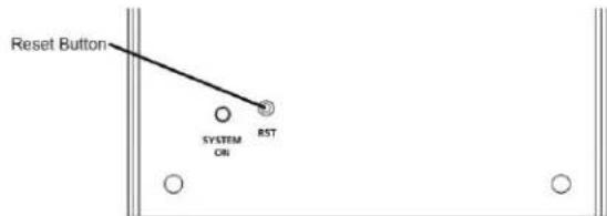
| Action | Result |
| Momentary | Soft Reset. Will not affect outlet state. |
| 5 Second Push | Reset to Factory Defaults. Hold until the “System On” LED is blinking, then release. |
| Hold while powering up | Recovery Mode. Allows upload of new firmware to Factory Default IP address of 192.168.1.254. |
X. SPECIFICATIONS
| Physical | |||||
| Model | Width | Depth | Height | Weight | # Outlets |
| SA-15-AR | 10.2” | 4.2” | 4.0” | 9 lb. | 2 |
| SA-20-AR | 10.2” | 4.2” | 4.0” | 9 lb. | 2 |
| Temperature | 5 - 35°C | ||||
| Humidity Range | 5% to 95% R.H., non-condensing | ||||
| AC | ||
| Load Rating | SA-15-AR | 15 Amps @ 120 Volts (1800W) |
| SA-20-AR | 20 Amps @ 120 Volts (2400W) | |
| Power Requirement (no load) | 10 Watts | |
| UL 1449-2 Adjunct Classification Test Results | 1000 surges, 6000 Volts, 3000 Amps,C1 pulse, measured suppressed voltage 290 Volts, no failures | |
| Maximum Applied Surge Pulse Joule Rating | Unlimited, due to current limiting (8 x 20 μs) | |
| Maximum Applied Surge Pulse Voltage | 6000 volts (1.2 x 50 μs pulse),industry standard rating | |
| Maximum Applied Surge Pulse Current | Unlimited, due to current limiting (8 x 20 μs)* | |
| Endurance | IEEE C62.41-1991 Category B3 (C1) | |
| Pulses | 1 kV>500,000; 3 kV>10,000; 6 kV>1000 | |
| EMI/RFI Filter | Normal Mode (50 Ω load) | 40 dB@100 kHz;50 dB@300 kHz;50 dB@3 MHz;50 dB@30 MHz |
| Common Mode (50 Ω load) | 18 dB@300 kHz; 30 dB@1 MHz;50 dB@5 MHz; 50 dB@20 MHz | |
| Network | |
| Single 10/100 Unshielded Twisted Pair Ethernet Jack | |
| IP Addressed: DHCP Assigned or Static | |
| Internal HTTP Web Server | |
| Forms Processing Browser Required | |
| Internal Telnet Server | |
| Compliance | |
| UL/cUL | UL60950 Listed I.T.E.File No. E225914UL 1449 3^rd Edition PendingUL 1283 5^th Edition Pending |
| CE | Directives 89/336/EEC, 92/31/EEC and 93/68/EECEN 60950: 3^rd EditionEN55022: 1998 Class B |
| FCC | Part 15 Class B |
*1.2 x 50 μs pulse, industry standard combination wave surge, as per IEEE C62.41
CAUTION: Do not install this device if there is not at least 10 meters (30 feet) or more between the electrical outlet and the electrical service panel.

- Axess-Ready Standalone Surge Elimination & Power Conditioning
- INTRODUCTION 2
- INSTALLATION 4
- LED INDICATORS 4
- INITIAL SET-UP 5
- WEB SERVER 8
- COMMAND LINE INTERFACE (CLI) PROTOCOL 16
- DXP PROTOCOL 20
- FIRMWARE UPGRADES 25
- RESET BUTTON 25
- SPECIFICATIONS 26
- INTRODUCTION
- INSTALLATION
- Physical
- Ethernet Connection
- AC Power Connections
- INITIAL SET-UP
- Device Management Utility (DMU)
- - Device
- - Manage
- - Set
- - Exit
- • Help
- Setting the IP Address
- WEB SERVER
- Password
- Control and Status Page
- Setup Pages
- ○ Device
- Network
- - Advanced Network
- ○ AutoPing
- Examples:
- ○ Schedule
- ○ Passwords
- COMMAND LINE INTERFACE (CLI) PROTOCOL
- DxP PROTOCOL
- Overview
- Hello Handshake
- DxP Packet
- ○ Header
- ○ Payload
- Commands
- Descriptors
- Payloads
- ○ TChangeRelay
- ○ TChangeRelays
- ○ TPulseRelay
- FIRMWARE UPGRADES
- RESET BUTTON
Brand : SurgeX
Model : SA-20
Category : Power Strip