DC2DC+ - Battery charger Enerdrive - Free user manual and instructions
Find the device manual for free DC2DC+ Enerdrive in PDF.


| Product Type | DC-DC Battery Charger |
| Model | DC2DC+ |
| Brand | Enerdrive |
| Input Voltage | 12V or 24V DC |
| Output Voltage | 12V or 24V (matched to battery) |
| Output Current | 20A (typical) |
| Dimensions (L x W x H) | 200 mm x 150 mm x 50 mm |
| Weight | 1.2 kg |
| Main Functions | Multi-stage charging (Bulk, Absorption, Float), compatible with AGM, Gel, Lithium batteries |
| Protection Features | Overvoltage, reverse polarity, overcurrent, overheating protection |
| Installation | Hardwired with screw terminals; suitable for marine, RV, and off-grid |
| Efficiency | >85% |
| Operating Temperature | -20°C to +50°C |
| Maintenance | Keep clean and dry; check connections periodically |
| Cleaning | Wipe with a dry cloth; do not use liquids |
| Safety Certifications | CE, RoHS compliant |
| Spare Parts | No user-serviceable parts; contact Enerdrive for repairs |
| Warranty | 2 years (typical) |
Frequently Asked Questions - DC2DC+ Enerdrive
User questions about DC2DC+ Enerdrive
0 question about this device. Answer the ones you know or ask your own.
Ask a new question about this device
Download the instructions for your Battery charger in PDF format for free! Find your manual DC2DC+ - Enerdrive and take your electronic device back in hand. On this page are published all the documents necessary for the use of your device. DC2DC+ by Enerdrive.
USER MANUAL DC2DC+ Enerdrive
DC2DC+ €POWER charger
Owner's Manual
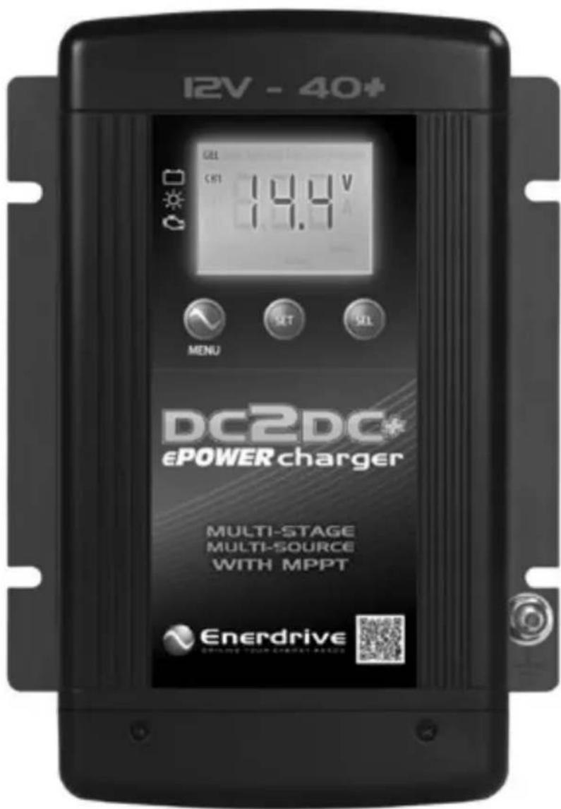
Table of Contents
1. Introduction 4
Please Keep This Manual For Future Reference 4
Disclaimer 4
Important Note 4
Product Numbers 4
Service Contact Information 4
Notice of Copyright 5
2. Warnings 6
Please read and follow the instructions and precautions carefully. 6
3. PRODUCT DESCRIPTION 8
4. UNDERSTANDING THE UNIT 9
Multistage Charging Process - GEL, AGM, Flooded & Program Modes 9
Lithium Charging Process 9
Smart Charging Feature 10
ePOWER charger algorithm 10
Lithium Battery charging algorithm 11
Battery Charger Voltage 11
Battery Bank Size Recommendation 12
EN3DC40+ (Current Settings): 12
5. INSTALLING THE CHARGER
Mounting The Charger 14
6. CONNECTING THE CHARGER
Chassis Grounding Connection 15
DC Output Wiring 15
DC2DC+ Battery Charger Connections 16
Recommended Cable Length, Size and Fuse Protection. 17
Standard Temperature Sensor Connection 18
Battery Wiring (Towing Applications): 19
Battery Wiring (Vehicle & Marine Applications): 20
7. UNIT OPERATION
Understanding The Charging Mechanism 21
Operating from a Start Battery / Alternator (CH3) 21
DC Input (CH2 - Solar / PV): 23
Maximising your Solar Harvest using the DC2DC+ 24
Understanding the Display & Function Keys during normal operation 25
Understanding The Function Key 'MENU', 'SET' And 'SEL' During Charger Setting 26
Digital Display: 26
Button Functions: 27
Automatic Override Functions: 28
Programming Your Charger 28
Understanding the Two-Stage (Mode 2) Charging 28
Understanding The Three-Stage (Mode 3) Charging 28
Understanding The Battery Temperature Functions 28
Battery Temperature Compensation: 29
Battery Temperature Sensor (BTS) Voltage Adjustment: 29
Procedure To Set Or View Charger Setting 29
Procedure To Equalise Flooded Batteries 30
Use the following procedure to setup the charger for battery equalisation. 30
Understanding The Protection Features 31
Charging A Flat Battery 31
Understanding The Display Codes 31
-
SPECIFICATIONS 34
-
WARRANTY 35
2 Year Limited Warranty 35
3 Year Pro Rata Support Program 35
Return and/or Repair Policy 35
Limitations 36
1. INTRODUCTION
Thank you for purchasing the Enerdrive ePOWER DC2DC+ Battery Charger. With our state of the art, easy to use design, this product will offer you reliable service for providing a multistage, multi-input battery charger to charge the different types of batteries you have installed in either your home, boat, caravan, 4WD or commercial vehicle. This manual will explain how to use this unit safely and effectively.
Please Keep This Manual For Future Reference
For safe and optimum performance, the Enerdrive ePOWER DC2DC+ Battery Charger must be used properly. Carefully read and follow all instructions and guidelines in this manual and give special attention to the CAUTION and WARNING statements.
Disclaimer
While every precaution has been taken to ensure the accuracy of the contents of this guide, Enerdrive assumes no responsibility for errors or omissions. Note the specifications and product functionality may change without notice.
Important Note
Please be sure to read the entire manual before using your Enerdrive ePOWER DC2DC+ Battery Charger. Misuse may result in damage to the unit and/or cause harm or serious injury. Read manual in its entirety before using the unit and save manual for future reference.
Product Numbers
| ePOWER DC2DC+ Battery Charger Series | |
| Product Number Product Description | |
| EN3DC40+ ePOWER DC2DC+ Battery Charger 12V / 40+Amp |
*ePOWER DC2DC+ Battery Charger Owners Manual Rev. 1.00.
This user manual is applicable to DC2DC+ models sold after July 2017 only.
Service Contact Information ENERDRIVE PTY LTD
P.O. Box 9159, Wynnum Plaza, Queensland, Australia 4178
Ph: 1300 851 535 / Fax: 07 3390 6911
Email: support@enerdrive.com.au
Web: www.enerdrive.com.au
Notice of Copyright
Enerdrive ePOWER DC2DC+ Battery Charger owner's manual © 2017 Enerdrive. All rights reserved. No part of this document may be reproduced in any form or disclosed to third parties without the express written permission of Enerdrive Pty Ltd, P.O. Box 9159, Wynnum Plaza, Queensland, Australia 4178. Enerdrive reserves the right to revise this document and to periodically make changes to the content hereof without obligation or organization of such revisions or changes, unless required to do so by prior arrangement.
Exclusions For Documentation And Product Usage
Unless specifically agreed to in writing, Enerdrive Pty Ltd: makes no warranty as to the accuracy, sufficiency or suitability of any technical or other information provided in its manuals or other documentation
Assumes no responsibility or liability for losses, damages, costs or expenses, whether special, direct, indirect, consequential or incidental, which might arise out of the use of such information. The use of any such information will be entirely at the user's risk
Reminds you that if this manual is in any language other than English although steps have been taken to maintain the accuracy of the translation, the accuracy cannot be guaranteed. Makes no warranty, either expressed or implied, including but not limited to any implied warranties of merchantability or fitness for a particular purpose, regarding these Enerdrive products and makes such Enerdrive products available solely on an “as is” basis
Shall in no event be liable to anyone for special, collateral, incidental, or consequential damages in connection with or arising out of purchase or use of these Enerdrive products. The sole and exclusive liability to Enerdrive, regardless of the form of action, shall not exceed the purchase price of the Enerdrive products described here in
2. WARNINGS
Please read and follow the instructions and precautions carefully.
This section contains important safety information for the Enerdrive ePOWER DC2DC+ Battery Charger. Each time, before using the Enerdrive ePOWER DC2DC+ Battery Charger. READ ALL instructions and cautionary markings on or provided with the DC2DC+ Battery Charger, and all appropriate sections of this guide.

CAUTION
This unit is intended for indoor use ONLY. It is not suitable for installation in an under bonnet vehicle application and such application will void warranty.
Battery Charger contains no user serviceable parts. See Warranty section for how to handle product issues.
Do not install the Enerdrive ePOWER DC2DC+ Battery charger in any vehicle engine bay or confined area where heat build up may occur.
Avoid moisture ingress. Never expose the unit to snow, water, etc..
WARNING: Shock Hazard.
Keep Away From Children!
WARNING: Fire &/or Chemical Burn Hazard!
When charging batteries they can release explosive and corrosive gasses / chemicals. Please wear safety glasses and protective clothing including gloves when working around batteries

LIMITATIONS OF USE
Do not use in connection with life support systems or other medical equipment or devices. The charger is not to be used by persons with reduced physical or mental capabilities or lack of knowledge and experience. Not to be operated or used by children.
WARNING
Explosion Hazard!
DO NOT use the Enerdrive ePOWER DC2DC+ Battery Charger in the vicinity of flammable fumes or gases (such as gas bottles).
AVOID covering the ventilation openings. Always operate unit in an open and well ventilated area.
Prolonged contact to high heat or freezing temperatures will decrease the working life of the unit.
WARNING
Failure To Follow These Instructions May Result In Death Or Serious Injury!
When working with electrical equipment or lead acid batteries, have someone nearby in case of an emergency.
Study and follow all the battery manufacturer's specific precautions when installing, using and servicing the battery connected to the charger.
Wear eye protection and gloves.
Avoid touching your eyes while using this unit.
Keep fresh water and soap on hand in the event battery acid comes in contact with eyes. If this occurs, cleanse right away with soap and water for a minimum of 15 minutes and seek medical attention.
Batteries produce explosive gases. DO NOT smoke or have an open spark or fire near the system.
Keep unit away from moist or damp areas.
Avoid dropping any metal tool or object on the battery. Doing so could create a spark or short circuit which goes through the battery or another electrical tool that may create an explosion.
3. PRODUCT DESCRIPTION
The Enerdrive ePOWER DC2DC+ Battery Charger is a multistage, multi-input battery charger to charge different types of batteries commonly installed in either boat's, caravan's, 4WD's or commercial vehicle's.
Enerdrive's ePOWER DC2DC+ Battery Charger package includes the following items;
| 1 x ePOWER DC2DC+ Battery Charger |  |
| 1 x Battery Temperature Sensor 7.5 Meter Cable) | 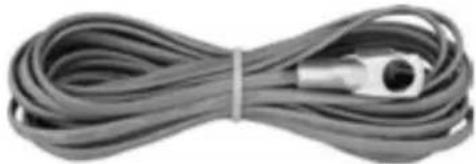 |
| 1 x Owner's manual |  |
4. UNDERSTANDING THE UNIT
The Enerdrive ePOWER DC2DC+ Battery Charger is a fully automatic multistage, multi input battery charger with the ability to charge from either an alternator linked to a battery; or via solar power with the in built Maximum Power Point Tracking (MPPT) Solar Controller. With two inputs available, the house battery will be charged from either the engine while underway, or via the solar panels when stationary. The process to choose either engine or solar is fully automatic and both functions are controlled from within the unit itself without the need for external relays.
During normal operation the ePOWER DC2DC+ Battery Charger will do a full charge cycle to float stage on the house battery bank with ability to choose either GEL, AGM, Flooded, Custom Programmable or Lithium. Once float stage is reached the charger transitions to a power supply mode to support on-board DC loads.
Multistage Charging Process - GEL, AGM, Flooded & Program Modes
The ePOWER DC2DC+ Battery Charger is a fully automatic, set and forget charger. It is designed to quickly and accurately recharge your deep cycle batteries utilising charger algorithms that help to maximise the life of your specialised deep cycle batteries.
The ePOWER DC2DC+ Battery Charger features multistage smart charging technology that enables the charger to be connected to your battery banks permanently. With the input of multiple sources, you can be assured of charging your batteries whenever underway; or when the sun is shining on your solar array.
As dictated by battery manufacturer's recommendations, deep cycle batteries require a multistage charge sequence for perfect, fast and accurate charging. The Enerdrive ePOWER DC2DC+ smart charger delivers three primary charge stages.
Stage 1 – Bulk or Boost charge; The battery is charged up to the full rated output current of the charger until the battery reaches its final charging voltage, known as its absorption voltage. In this step, around 80% of the battery is recovered as fast as possible.
Stage 2 – Absorption Charge; With the charger voltage held steady, the remaining 20% is replaced with the charger allowing the current to taper off as the battery approaches full charge.
Stage 3 – Float; Finally, in the float stage the charger voltage is lowered and held at a constant and safe predetermined level. This prevents the battery from being overcharged, yet allows the charger to supply enough current to make up for the self-discharge losses of the battery, while supporting additional loads connected to the battery (such as DC lighting and refrigerators). This stage allows for the charger to be used as a DC power supply.
Lithium Charging Process
The ePOWER DC2DC+ charger has a specific charging profile for Lithium batteries. It has its own charging voltage and current settings that needs to be set by the user. It also requires the user to set the charger termination current ("L" setting). Once the user defined charge voltage is reached, the charger will start reducing the current output and the charging process will terminate when the charging current drops to the set termination current. This can take anywhere between 3 to 15 minutes. The unit will then act as a power supply to support
additional loads connected to the battery while the DC2DC+ is powered from either the vehicle or solar inputs. A Bulk re-start will occur when battery voltage drops below 13.3V DC.
Smart Charging Feature
The ePOWER DC2DC+ Battery Charger will regulate its output based on the loads connected to your battery banks. This function is important to maintain the life of your battery banks as some battery chargers mistake loads for discharge and continue to keep the batteries in the bulk or absorption stage for extended periods of time, which will damage the battery bank. The ePOWER DC2DC+ Battery Charger has two methods of load based regulation to ensure your battery charger transitions to float when it should do so.
ePOWER charger algorithm
Battery Charging Curve For GEL, AGM, Flooded & Program Batteries:
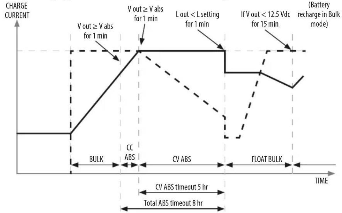
line
| Time Segment | Description | | ------------------------- | ------------------------------------- | | Start | CHARGE CURRENT (BULK) | | Peak | V out ≥ V abs for 1 min | | Midpoint | V out ≥ V abs for 1 min | | Final | L out < L setting for 1 min | | Final | If V out < 12.5 Vdc for 15 min | | Final | Battery recharge in Bulk mode |-
-
-
-
- Battery Charging Curve (Current) Battery Charging Curve (Voltage)
-
-
-
Lithium Battery charging algorithm

line
| Phase | Battery Current (V) | Battery Voltage (V) | | :--- | :--- | :--- | | Bulk Power Supply Mode | 14.2 | 13.0 | | Maint. Power Supply Mode Return to Bulk | 13.5 | 13.6 | | 13.3VDC triggers Bulk Restart | 13.3 | 13.3 | Time out 8 hrs max Time out 7 daysDiagram does not illustrate our current set points.
Note: Actual voltages depend on chosen algorithm.
Battery Charger Voltage
| Battery Type | Absorption | Float (See Note 3) | Equalisation |
| GEL 14.4 V 13.7 V N.A. | |||
| AGM 14.6 V 13.6 V N.A. | |||
| Flooded | 14.4 V | 13.3 V | 15.5 V (See Note1) |
| Lithium | 13.9 V-14.6V (0.1V Step)(see Note2) | 13.5V-14.2V(0.1V Step) | N.A |
| Program (Custom Settings) | 13.8V-14.8 (0.1V Step) | 13.0V-13.8 (0.1V Step) | N.A |
* For Concorde™ branded batteries (lifeline, sun xtender) use flooded setting and consult battery supplier for equalisation recommendations.
Note 1: Equalisation setting can only be used on flooded battery type selection only. See more details on Procedure to Equalise the Flooded Battery.
Note 2: Charger will terminate charging when charging current drops to below the set charger termination value.
Note 3: Charger is acting as a power supply with selected constant output voltage and preset maximum output current.
NOTE: The equalisation function although included in the ePOWER DC2DC+ will rarely be used. To activate, the battery bank must be in float, and manually activated. A typical drive will not be long enough for the DC2DC function to complete the process. The MPPT Solar function may provide enough time for Equalisation, but the best recommendation will be an AC powered battery charger.
Battery Bank Size Recommendation
The battery charging current rating is based on the battery size. The battery bank should meet the minimum Ah rating as shown. If a smaller size battery bank is used, set the current rating to a lower value to match with the battery bank size. Normally, the minimum battery bank capacity is based on a C5 rating of the battery for charging.
| EN3DC40+ | ||||||
| Current Setting | 5A | 10A | 20A | 30A | 40A | 50A |
| Battery Capacity | Min 25Ah | Min 50Ah | Min 100Ah | Min 150Ah | Min 200Ah | Min 250Ah |
EN3DC40+ (Current Settings):
| EN3DC40+ Available Current Settings | |||||
| Bulk(“h” Setting) | 5A 10A | 15A 20A 25A | |||
| ABS Float(“L” Setting) | 1A/1.5A/2A | 1A/1.5A/2A | 1A/1.5A/3A | 2A/3A/4A | 2A/4A/5A |
| Bulk(“h” Setting) | 30A | 35A | 40A | 45A | 50A |
| ABS Float(“L” Setting) | 3A/4A/6A | 3A/5A/7A | 4A/6A/8A | 4A/6A/9A | 5A/7A/10A |
Use the above table to set the Bulk and its related Absorption (ABS) to Float Charge Current.
IMPORTANT NOTE: If in doubt of the "L" setting, use the highest available current setting for battery protection.
5. INSTALLING THE CHARGER
WARNING
Enerdrive recommends that all wiring be done by a skilled technician to ensure adherence to the best practice standards for on-board DC electrical installations. Failure to follow these instructions can damage the unit and could also result in personal injury or loss of life.

CAUTION
Before Installing The Unit Consider The Following:
This unit is designed ONLY for internal mounting and should be used or stored in an indoor area away from direct sunlight, heat, moisture or conductive contaminants.
DO NOT INSTALL IN VEHICLE ENGINE BAY
This is an electronic device cooled by a fan, and will prematurely fail if installed in corrosive / moisture rich environments.
When placing the unit, allow a minimum of 75mm of space around the unit for optimal ventilation.

NOTE
The Enerdrive ePOWER DC2DC+ Battery Charger is designed to be permanently mounted.
Mounting The Charger
- Choose an appropriate mounting location.
- For installing in an indoor location, the unit should be mounted vertically (with the battery terminals facing downwards). This provides the best thermal performance and drip protection. The unit should NOT be mounted upside down.
- For installing in a boat or marine environment, the unit should only be mounted vertically (Battery Terminals facing downwards only) to provide adequate drip protection.
- Use the base of the charger as a mounting template to mark the positions of the fixing screws.
- Drill the 4 fixing holes and place the Charger in position and fasten the unit to the mounting surface.

6. CONNECTING THE CHARGER
Chassis Grounding Connection

BEST PRACTICE
This Charger SHOULD BE CORRECTLY GROUNDED.
The unit chassis has a stud point on it for grounding. Connect the unit's chassis ground to the common ground point through the ground stud located near one of the unit mounting slots. (Battery DC negative is the best ground reference point in your installation).
DC Output Wiring

WARNING: Correct DC Wiring Is Required
The DC wiring used must be of appropriate size.
An individual fuse or breaker is required to be installed within 20cm of the both the start battery and house battery bank.
A DC isolator or fuse is also recommended for the solar input.
All devices must be rated for DC voltage and current.
The solar input fuse or breaker must be able to withstand the short circuit current rating stated on the solar panel array.
All wiring must conform or exceed the recommendations stated in this manual (page 17).
This is a Dual Input device. Different cable sizes are required for the alternator input, solar array input and the DC2DC+ charger to battery connection.
DC2DC+ Battery Charger Connections

Start Battery House BatterySolar Array
Recommended Cable Length, Size and Fuse Protection.
| DC2DC Connection Inputs | Require Length & Battery Cable Size | ||
| DC2DC set to=<30A Output | 2 Meters to 5Meters (2) | Up to 10Meters (2) | Greater than10 Meters |
| From Alternator Battery | 6-16mm ^2 @ 12vdc/ 4-8mm ^2 @ 24vdc | 16-35mm ^2 @ 12vdc/ 8-16mm ^2 @ 24vdc | Not Recommended |
| Primary Battery Connection (2) | 16mm ^2 Not Recommended Not Recommended | ||
| DC2DC Connection Inputs | Require Length & Battery Cable Size | ||
| DC2DC set to=<40A Output | 2 Meters to 5Meters (2) | Up to 10Meters (2) | Greater than10 Meters |
| From Alternator Battery | 10-25mm^2 @ 12vdc / 10mm^2 @ 24vdc | 25-50mm^2 @ 12vdc / 25mm^2 @ 24vdc | Not Recommended |
| Primary Battery Connection (2) | 16-25mm^2 | Not Recommended Not Recommended | |
| DC2DC Connection Inputs | Require Length & Battery Cable Size | ||
| DC2DC set to 50A Output | 2 Meters to 5 Meters (2) | Up to 10 Meters (2) | Greater than 10 Meters |
| From Alternator Battery | 16-25mm^2 @ 12vdc / 8-10mm^2 @ 24vdc | 35-50mm^2 @ 12vdc / 16-25mm^2 @ 24vdc | Not Recommended |
| Primary Battery Connection (2) | 16-25mm^2 | Not Recommended Not Recommended | |
Note: Cable size quoted is one way from battery to device, however suggested cable size is calculated with return run.
1) Note: If solar panels are wired in Series (increased voltage), then typically 1 × 4mm^-2 cable run per series string is suitable.
2) Based on 3% voltage drop.
| Recommended Fuse Protection | |
| From Alternator Battery | 70amp Fuse or Circuit Breaker no greater than 20cm from source battery.PLEASE NOTE: Automatic re-settable circuit breakers are NOT recommended. |
| From Solar Panels | Fusing recommended no greater than 20cm from input to DC2DC+ Charger. Typically 15amps per solar panel (consult your panel specifications for further details). |
| Primary Battery Connection | 60amp Fuse or Circuit Breaker. |
Standard Temperature Sensor Connection
- To install the temperature sensor, simply connect the RJ12 plug from the sensor to the RJ12 Temperature Sensor Port located next to the Remote Port.
- On the temperature sensor end, simply connect the ring terminals to the negative terminal of the main house battery bank.
PLEASE NOTE: For lithium installations, the standard supplied temperature sensor is not required to be installed for these applications.
Battery Wiring (Towing Applications):
For Towed Applications i.e. Caravans, Camper Trailers

flowchart
graph TD
    A["DC2DC+ ePOWER charger"] -->|14.4V| B["Motor"]
    B --> C["Fuse Size 1A"]
    C --> D["Anderson Plug (Optional)"]
    D --> E["Start / Vehicle Battery 12V or 24V"]
    D --> F["Smart alternator battery sense module"]
    D --> G["Temp Sensor Cable (Included)"]
    G --> H["Fuse / Breaker 60A"]
    H --> I["12V House Battery Bank"]
    I --> J["MPPT Solar Panel Input Max: 500w / 45VOC (For fixed or portable panels)"]
    D --> K["Fuse / Breaker 12V - 70A 24V - 40A"]
    K --> L["Motor with a Smart alternator, negative cable must be connected to the vehicle side of the Battery Sense Module."]
    style A fill:#f9f,stroke:#333
    style B fill:#ccf,stroke:#333
    style I fill:#cfc,stroke:#333
    style J fill:#fcc,stroke:#333
    style K fill:#cff,stroke:#333
    style L fill:#ffc,stroke:#333
This diagram is for a reference only. No cables, fuse/breakers, batteries or solar panels are supplied with this unit.
Local rules and regulations should be followed when installing this unit.
Battery Wiring (Vehicle & Marine Applications):
For In Vehicle & Marine Installation. i.e. Motorhomes, 4WD's & Trucks.

POSITIVE WIRE NEGATIVE WIRE TEMPERATURE SENSOR
CABLE (INCLUDED)
This diagram is for a reference only. No cables, fuse/breakers, batteries or solar panels are supplied with this unit.
Local rules and regulations should be followed when installing this unit.
7. UNIT OPERATION
Understanding The Charging Mechanism
Note 1: The Charger is powered by the battery connected to DC Output (CH1) and also supplied by CH2 or CH3 if available. The display will turn off to save power when Input Channel CH2 and CH3 are out of operating range.
Operating from a Start Battery / Alternator (CH3)
| Normal Operation: | Input Battery / Source | |
| 12V Input 24V Input | ||
| Input Voltage Range 10.5V – 16.0V 21.0– 32.0V | ||
| Normal Start-Up Voltage (Note A) > 13.2V > 26.4V | ||
| Normal Under Voltage Recovery Voltage (Note A) | > 12.8V | > 25.6V |
| Ignition Sense Terminal | Ignition Sense Terminal must see a minimum of 10.5V to trigger low voltage “Priority Mode”. | |
| Low Start-Up Voltage (using Ignition Sense Terminal or using Manual Over-ride setting) (Note B) | > 12.3V > 24.6V | |
| Low Under Voltage Recovery Voltage (Note B) | > 12.0V | > 24.0V |
| De-Rated Voltage (with load) (Note C) | 11.5V | 23.0V |
| Under Voltage Shutdown (with load) | 10.5V | 21.0V |
| Over Voltage Shutdown | 16.0V | 32.0V |
| Over Voltage Recovery | 15.5V | 31.0V |
| Input Battery System Reset Voltage (NoteD) | < 7V | < 7V |
| Maximum Input Current - EN3DC40+ | 50A | 50A |
Note A:
When the battery is charging through CH3 with normal operation (not through Ignition or override setting), the charger will charge for 3 minutes, it will then rest for 5 seconds to verify the Input voltage.
During the 5 seconds rest period, if the measured voltage is >12.8Vdc on a 12V System (>25.6Vdc on a 24V system), the unit will continue the charging cycle through CH3.
If the measured voltage on CH3 is <12.8Vdc (<25.6Vdc on a 24V system), the unit will disconnect from the vehicle source and switch back to charge from CH2 (solar if installed) until the CH3 voltage returns to >13.2Vdc on a 12V System (>26.4V on a 24V system).
Also, during the 3 minutes charging process, if the measured terminal voltage drops below <11.5V for a 12V system, (<23V for a 24V system), the charger will start to derate the output
current. This function is used to compensate for the use of long or thin wire between the Input Battery System and the unit input terminals. If the input voltage continues to drop below the <10.5V for a 12V system (<21V for a 24V system), the charging process will terminate and the unit will switch back to charge from CH2 (solar if installed) if installed. It will only switch back to CH3 if the CH3 voltage is >13.2V on a 12V system (>26.4V on a 24V system.
Note B:
When the unit has activated the battery charging process using the ignition sense terminal (Priority Mode) or using the Manual Override through the unit setting, the input voltage specification is reduced. It has the same charging process but with a Low Start-Up Voltage set to >12.3Vdc 12V system (>24.6V on a 24V system). This feature is designed to be used for vehicles fitted with “Smart Alternators”.
If the measured voltage on CH3 is <12.0 Vdc (<24Vdc on a 24V system), the unit will disconnect from the vehicle source and switch back to charge from CH2 (solar if installed) until the CH3 voltage returns to >12.3Vdc on a 12V System (>24.6V on a 24V system).
The Low Under Voltage Recovery Voltage is set to > 12V (from 12.8V) on a 12V system and > 24V (from 26.4V) on a 24V system. During the 5 second rest period, if the input voltage returns above 12V/24V, it will continue the charging process and if the input voltage does not return to > 12V/24V, it will switch back to charge from the Solar - CH2 (if connected) until the Start - CH3 input has returned to the Low Start-Up voltage of 12.3V on a 12V system and 24.6V on a 24V system.
Note C:
During the 3 minute charging process, if the measured terminal voltage drops below the Under Voltage de-rated limit (11.5V for a 12V system, 23V for a 24V system), the charger will start to de-rate the charger current. This function is used to compensate the use of long or thin cable between the Input Battery and the unit terminals. If the voltage continues to drop to below the Under Voltage Shutdown limit of (10.5V for a 12V system and 21V for a 24V system), the charging process will terminate and the unit will switch back to charge from CH2 (solar if installed). It will only switch back to CH3 if the CH3 voltage returns to 13.2V (12.3v with ignition sense connected) on a 12V system and 26.4V (24.6V with ignition sense connected) on a 24V system.
Note D:
The CH3 DC Input (Battery Input) can accept a 12V or 24V battery with an alternator system. When the unit is first connected, the unit will measure the input voltage. If the voltage is >17V, it will assume it is connected to a 24V Input Battery/Alternator system. If the voltage detect is < 17V, it will assume it is connected to a 12V Input Battery/Alternator system. Once detected, it will store this into the microprocessor and it will only be erased if the Input battery is disconnected or if the measured Input Voltage drops to < 7Vdc.
DC Input (CH2 - Solar / PV):
| PV Input Voltage Range 14.5 - 45V | |
| PV Input Under Voltage Shutdown < 14.5V | |
| PV Input Under Voltage Recovery 15.0V | |
| PV Input Over Voltage Shutdown > 45V | |
| PV Input Over Voltage Recovery = < 44V | |
| PV Charging Mechanism MPPT type ( approx. 97% efficiency) | |
| Maximum Input | 500W *See Note below and “Maximising your Solar Harvest using the DC2DC+” |
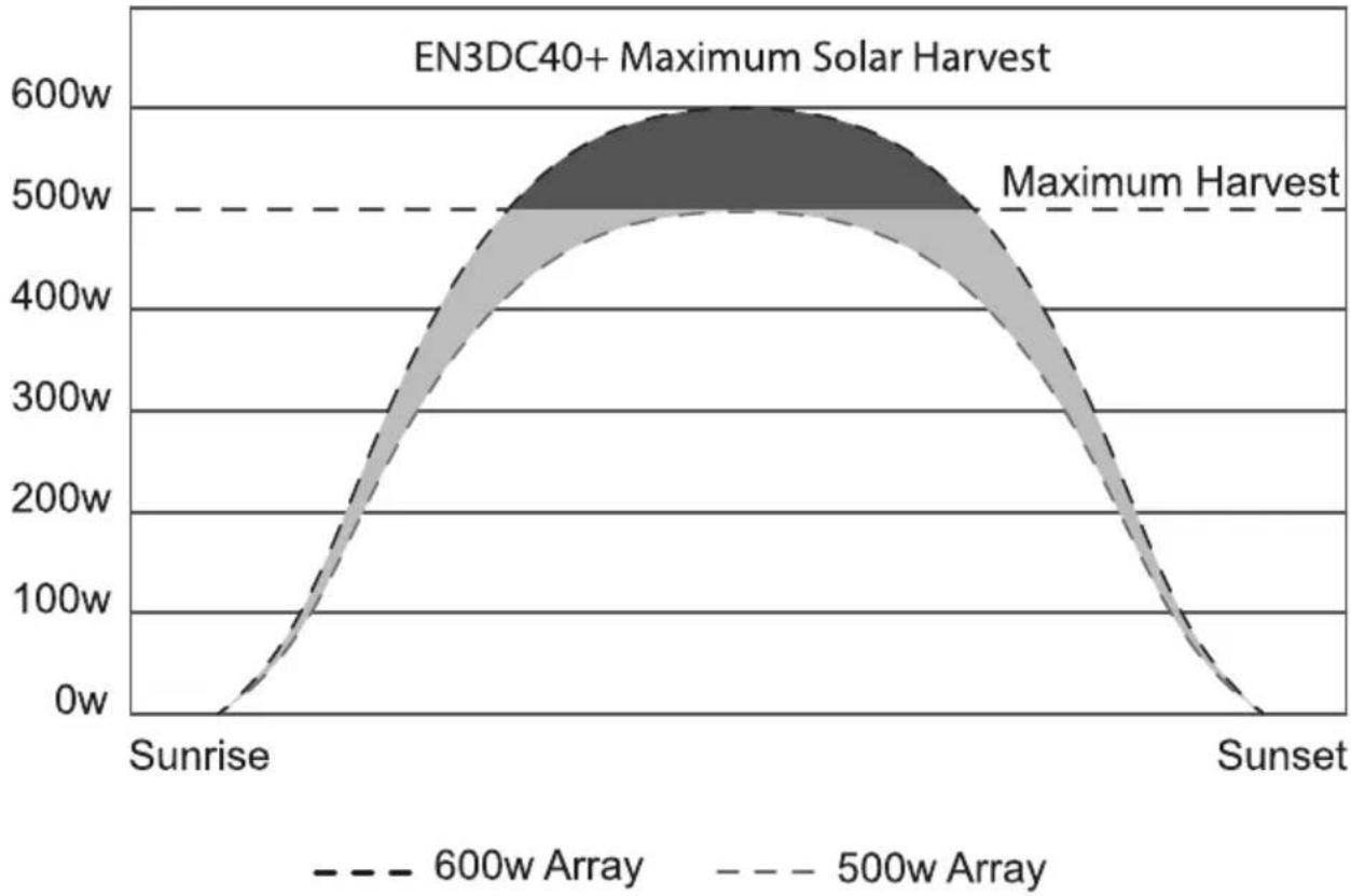
*Note: The recommended maximum solar wattage input for the DC2DC+ Charger is 500w. You can however “overdrive” the MPPT controller. Please note that doing this is partially an economic decision. You can install more power than the controller can use and this will contribute to better power availability. Enerdrive suggest a total maximum overdrive of 20% (total 600w). On cloudy (or intermittent sunny) days there will be little or no power shaving and the extra power will serve the battery well with more energy harvest earlier and later in the day.
line
| Day | 600w Array | 500w Array | | ------- | ---------- | ---------- | | Sunrise | 0w | 0w | | Peak | ~580w | ~500w | | Sunset | 0w | 0w |Maximising your Solar Harvest using the DC2DC+
The Solar Input on the DC2DC+ unit has a maximum rated INPUT current of 30amps. This means it is optimised for using higher voltage 'grid' type modules for best output performance The maximum achievable output using standard 20Voc solar modules will be approximately 35amps @ 14.4Vdc output.
| Panel Array Rated Wattage & Volts Open Circuit rating | Estimated DC Amps Output (## See Below) | ||
| 1 150watt @ 20Voc 150watts 10 | |||
| 1 200watt @ 43Voc 200watts 13 | |||
| 2 150watt @ 20Voc 300watts 21 | |||
| 2 200watt @ 43Voc 400watts 27 | |||
| 3 150watt @ 20Voc 450watts 31 | |||
| 3 200watt @ 43Voc 600watts 42 | |||
| 4 150watt @ 20Voc 600watts 35* | |||
| 4 200watt @ 43Voc 800watts 47** | |||
| 5 | 150watt @ 20Voc | 750watts | Not Recommended |
| 5 | 200watt @ 43Voc | 1000watts | Not Recommended |
* Maximum achievable output on the DC2DC+ unit when using 20Voc Solar Panels will be the approximately 35amps.
** Maximum achievable output on the DC2DC+ unit when using 43Voc Solar Panels will be the approximately 47amps.
## IMPORTANT NOTE: Estimated Amps Output is quoted based upon PERFECT Solar conditions including Sun Angle, Panel Mounting angle and Orientation to the sun. It needs to be noted that panel performance alters dramatically between Summer and Winter periods and actual performance may be impossible to predict.
Understanding the Display & Function Keys during normal operation
| Display | |
| Digital Display LCD with back lighting | |
| Digital Display Info : CH1CH2 & CH3Fault/Warning | Charging Status, Voltage, Current VoltageError code E01-08, Warning A01-02 |
| ‘CH3’ Icon Flashing | CH3 > 12.0V on a 12V Input systemCH3 > 24.0V on a 24V Input system and not charging from (alternator) |
| ‘CH3’ Icon Solid Charging from CH3 input (Start Battery / Alternator) | |
| ‘CH2’ Icon Flashing CH2 > 14.5V and not charging | from solar array |
| ‘CH2’ Icon Solid Charging from CH2 input (solar) | |
- During normal operation, the display will cycle through and show CH1 battery voltage, charging current and charging stage ('bul' – Bulk stage, 'Abs' – Absorption stage, 'Ful' – Float stage) alternatively. When the 'MENU' key is pressed, it will display the other channel's battery voltage only
- CH3 icon will flash when the input voltage is above (> 12 on a 12V system or > 24V on a 24V system and it is not the source charging the battery. It will change to solid when it becomes the source charging the battery.
- CH2 icon will flash when the input voltage is above the Flashing Voltage (> 14.5V) and is not the source charging the battery. It will change to solid when it becomes the source charging the battery.
- During normal operation, Every time the menu button is pressed once, the display will scroll through and show CH1, CH2 & CH3: Voltage' for 3 seconds and it will return to the normal display automatically. If CH2 or CH3 is not connected, it will show 0V.
- The display will remain ON when either one or both CH2 & CH3 inputs are available. The display will turn OFF if CH2 or CH3 is not available.
- During equalisation operation (for flooded batteries only), the numerical section on the display will show a flashing 'eq' indicating the equalisation process is in progress and it will not show the battery voltage or the charging current.
Understanding The Function Key 'MENU', 'SET' And 'SEL' During Charger Setting
CH1 - display is showing the charging battery info (charging status, voltage and current).
CH2 or CH3 - When displayed symbol is solid this means the power is coming from the related channel and the other channel will be flashing if it is connected but not charging.
"V" - Display is showing the voltage
"A" - display is showing the current
"Auto" - units Silent mode is switched on
"Priority" - the units "ignition Sense" terminal is connected or the unit is set to Manual Override mode
"Mode" - charging mode setting*
"Temp" - Temperature setting*
*Will only display when selected setting is active

Digital Display:
- During the charging process, the display shows 'CH1' charging status, voltage and current repeatedly, and 'CH2' or 'CH3' symbol is solid to indicate the active input source. If the other input channel is available and the voltage is above the 'CH2 and CH3 Flashing Voltage' the icon will be flashing. When the menu button is pressed once, the display will change to show CH1 Voltage for 3 seconds, CH2 voltage for 3 seconds and CH3 voltage for 3 seconds. The display will then revert back to normal operation and will show the CH1 info.
- When the Battery (CH1) is fully charged, it will show 'CH1' and 'FLO', voltage and current repeatedly on the display.
- The selected "battery type" icon is always ON at all times during the whole charging process.
- The 'Priority' Icon turns ON when the "ignition sense" terminal is connected or the unit is set to 'Manual Override' mode.
Button Functions:
 MENU MENU | ·During normal charging operation, press once to change the display to show·CH1, CH2 and CH3 voltage.·During normal charging operation, press and hold for more than 3 seconds to enter Charger Function Setting Menu·When CH2 or CH3 is not available (voltage detect is below the sense voltage), display will turn OFF. Press once will temporary trigger on the display and it will automatically cycle through all three channels voltage, the software revision and then turn off. |
 | ·During the charger Setup Menu, this button is used to confirm the setting and continue to the next menu.·Manual Override Mode: During normal operation, when the input source is charging from CH2, press and hold for more than 10 seconds to turn Priority mode ON, 'Priority' icon on display will turn ON. This will force the charger from being connected to CH2 and connect it to CH3 (subject to CH3 being 12.3v or 24.6V or higher). If CH3 is not connected or out of operating range, it will go back to CH2. This setting mode is used when CH2 (Solar) is available but the charging current is too small due to the availability of sunlight. Use the same procedure to turn off the 'Manual Override' mode when not required.·Please Note:If Manual Override Mode is used and left on there is a risk of flattening the start battery. The preferred method is to use the automatic override method by connecting the ignition source to the ignition terminal of the DC2DC+ charger.·With Flooded Battery Type setting, press and hold the "SET" and "SEL" buttons together for more than 5 seconds will force the charger into Equalized Mode and it will start equalizing the flooded battery. Please note; the battery has to be set to 'Flooded' battery type in-order to have this function activated. |
 | ·During the charger Setup Menu, this button is used to change to the next available setting.·'Silent' mode (Fan OFF mode): During normal operation, Press and hold for more than 10 seconds will force the fan to turn OFF. 'Auto' icon will turn ON. The charger current will reduce to half of the set current. The unit will go back to normal after 12 hours and the 'Auto' icon will turn OFF.·Note:Every time the "MENU", "SET" and/or "SEL" buttons are pressed, the back light will illuminate and will automatically turn off after 60 seconds. |
Automatic Override Functions:
When positive power is applied to the "Ignition Sense" terminal (do not connect to ground), it will force the charger to connect to CH3 as long as CH3 is within the voltage range >12.3V or 24.6V on a 24v input.
Programming Your Charger
| MENU | Press and hold the key for longer than 3 seconds to enter charger setting mode and show function setting. Once new setting is done, press ‘MENU’ again for longer than 3 seconds to exit the charger setting mode. |
| SET | Press the key once to keep / save the chosen setting and change the display to show the next menu to continue other settings.Note: The selected setting will quickly flash 3 times to acknowledge the setting. |
| SEL | Press the key to view other available settings. |
Understanding the Two-Stage (Mode 2) Charging (Default setting is 3)
The DC2DC+ can be set to act as a 2 stage charger (Bulk/Float). Certain applications may require a 2 stage charge process and by setting this option, the DC2DC+ unit will act accordingly to meet this requirement.
During the Bulk stage, the battery accepts the maximum constant current from the charger. In Float stage, the charger continuously produces a lower constant float voltage to maintain the battery in a fully charged stage.
Understanding The Three-Stage (Mode 3) Charging
The Three-Stage Charging (Mode 3) has a Bulk/Absorption/Float sequence. During the Bulk stage, the battery accepts the maximum constant current from the charger. In the Absorption stage, the battery voltage is held to constant voltage and the charging current will slowly reduce. In Float stage, the charger continuously produces lower constant float voltage to fully top up and maintain the battery in a fully charged stage.
The charger will automatically restart the full charging cycle if it senses the battery bank is discharged to lower than 12.5V for lead acid batteries and 13.3V for lithium batteries.
Understanding The Battery Temperature Functions
The Battery Temperature Sensor is included with the charger to protect your battery and provide better charging voltage accuracy.
When the battery temperature sensor output is used, it is highly recommended to be installed on the main battery bank at the negative terminal. The sensor senses the battery
temperature and overrides the manual temperature settings and makes small adjustments to the charging voltage.
If using lithium batteries, leave temp set to "NOR" (Normal) and leave temp sensor disconnected.
Battery Temperature Compensation:
There are three manual battery temperature settings on the unit ('Lo', 'nor' and 'hi'). See the table below for voltage adjustments for temperature compensation.
| Temperature Setting | Recommended Battery Temperature | Battery Type | Voltage adjustment from 25°C normal setting |
| Low (Lo) < 5°C | GEL, Flooded + 0.675 V | ||
| AGM + 0.525 V | |||
| Normal (Nor) > 5°C and < 30°C | GEL, Flooded 0 V | ||
| AGM 0 V | |||
| High (HI) > 30°C | GEL, Flooded - 0.27 V | ||
| AGM - 0.21 V |
Battery Temperature Sensor (BTS) Voltage Adjustment:
| Battery Temperature | Battery Charging Voltage Adjustment from 25°C | |
| Flooded and GEL type AGM type | ||
| < 25°C + 0.027V / °C + 0.021V / °C | ||
| 25°C 0V | 0V | |
| >25°C | -0.027 / °C | -0.021 / °C |
Note: The above voltage compensation will only work with the supplied Battery Temperature Sensor fitted which will override the unit temperatures' (Lo, Nor, Hi) setting. If using lithium batteries, leave temp setting "NOR" (Normal) and leave temp sensor disconnected.
Procedure To Set Or View Charger Setting
Follow the procedure or sequence in Appendix A1 and A2 (see back of this manual) to set or view the charger setting.
Procedure To Equalise Flooded Batteries

DANGER
Explosion Hazard And Risk Of Battery Damage.
The battery generates explosive gases during equalisation. Follow all the battery safety precautions listed in the manual.
When using the equalisation mode, the user has to be sure the battery connected to the battery charger is a flooded battery type. Equalizing a non-flooded battery may overcharge the battery and may cause the battery to explode.

CAUTION
Risk of battery and equipment damage.
Only Flooded lead-acid can be equalised. Consult your battery manufacturer or read the battery manual when you try to equalise your batteries.
Disconnect any DC load connected to the battery, as during equalise mode, the charger will produce 15.5V to the batteries. You must monitor the battery specific gravity throughout the equalisation process to determine the end of the equalising cycle.
Before setting the equalisation mode, please be sure the battery is a flooded battery type. When the battery equalisation has started, the charger will automatically fully charge the battery bank and will then follow with 1 hour of equalisation. Check the battery electrolyte level during the equalisation period. If necessary, refill with distilled water only. All cells should have similar electrolyte levels. If distilled water is added, batteries must undergo a complete charge cycle. The charger cannot determine when to terminate the equalisation of the battery, a one hour time-out is set and this is used as a safety feature to require the user to continually re-activate it as necessary after checking batteries manually.
Use the following procedure to setup the charger for battery equalisation.
With Flooded Battery Type setting, Press and Hold Button "SET" and "SEL" together for more than 5 seconds. This will force the charger to go into to Equalized mode and it will start equalizing the flooded battery. Please note the battery mode setting has to be set to 'Flooded' battery type in-order to have this function activated.
Understanding The Protection Features
De-rating Charging Current:
When the charger senses the environmental temperature is above 50^ , the maximum charger current will de-rate to 1/2 of the set value (A01 warning code will display). The charger will recover automatically back to maximum charging current when the environmental temperature drops to below 45^ .
Over Temperature Shutdown:
When the charger senses the environmental temperature is above 60^ C , the charger will shutdown. It will recover automatically when the environmental temperature drops to below 45^ C .
Battery Reverse Polarity:
When a reverse polarity is connected to the battery bank, "Error Code E08" on the display will appear.
Charging A Flat Battery
The charger is designed to charge batteries with terminal voltage greater than 8.0Vdc.
Re-charging a flat battery requires extreme care and attention. It is best to re-charge using short frequent cycles rather than one long bulk cycle. Battery damage or failure may occur if the battery is discharged so deeply.
Understanding The Display Codes
Codes will show on the display when either a function or internal warning / fault, such as high internal temperature or DC out of range is detected and the charger may shut down to protect itself until the fault has cleared. See table description below for more information.
| Code Description | |
| BUL | The charger is in Bulk Charging ModeBulk or Boost charge; The battery is charged at the set rated output current of the charger until the battery reaches its final charging voltage, known as its absorption voltage. In this step, around 80% of the battery is recovered as fast as possible. |
| Abs | The Charger is in Absorption Charging ModeAbsorption Charge; With the charger voltage held steady, the remaining 20% is replaced with the charger allowing the current to taper off as the battery approaches full charge. |
| FUL | The charger is in Float Charging & Power Supply ModeFloat; Finally, in the float stage the charger voltage is lowered and held at a constant and safe predetermined level. This prevents the battery from being overcharged, yet allows the charger to supply enough current to make up for the self-discharge losses of the battery, while supporting additional loads connected to the battery (such as DC lighting and refrigerators). This stage allows for the charger to be used as a DC power supply. |
| CHE | CH3 Input Voltage CheckThis will display for 5 seconds every 3 minutes while charging from the alternator input (CH3) and is normal operation when the charger is checking the under voltage recovery limit (see page 18 for details). |
| E01 | CH3 High Input Voltage ShutdownThis means the unit has detected the input from the Start/Alternator has gone above 16.0V on a 12V input or 32.0V on a 24V input. This error will clear once the input has dropped below 15.5V on a 12V input or 31.0V on a 24V input. |
| E02 | CH3 Low Input Voltage ShutdownThis means the unit has detected that the input from the Start/Alternator has gone below 10.5V on a 12V input or 21.0V on a 24V input. This error will clear once the input has risen above 13.2V on a 12V input or 26.4V on a 24V input.If you have this error:Check that the voltage of your Start Battery is above 13.2V on a 12V input or 26.4V on a 24V input.Check that you have not left the "Priority" (Override) feature activated (Manual or Auto)Check that the battery cable from the Start Battery is correctly sized.Check you don't have a loose terminal or blown fuse. |
| E03 | CH2 High Input Voltage ShutdownThis means the unit has detected the input from the solar has gone above 45.0V. This error will clear once the input has dropped below 44.0V.If you have this error:Check the specification of your panels - the Volts Open Circuit (VOC) should not exceed 45VOCMake sure the solar panels have not been connected in series as this will increase the VOC voltage of the panel array.Please Note: Maximum solar VOC input must not exceed 45VOC or damage to the unit will occur. |
| E04 | CH2 Low Input Voltage ShutdownThis means the unit has detected the input from the Solar Array cannot sustain voltage above 14.5v.If you have this error:Check that you are not in a low light/non direct sunlight situation i.e. Early morning / late afternoon.This may also happen if your solar panels are inside in a shed with a skylight or Hi Bay Lights running or outside under Flood Lights.If you find this is happening with your unit when stored, we recommend fitting a DC Breaker to the output of the DC2DC+ and turning it off when the unit is not in use/storage. |
| E05 | CH1 High Input Voltage ShutdownThis means the unit has detected that the Main/House battery has gone above 16.0V. This error will clear once the input has dropped below 15.5V.This may be due to charging from another source. i.e. Another solar controller or AC battery charger. |
| E06 | Over Temperature ShutdownWhen the charger senses the environmental temperature above 60°C, the charger will Shut down. It will recover automatically when the environmental temperature drops below 45°C.Check to make sure the fan is working.Make sure the unit has good ventilation. |
| E07 | BTS Over Temperature ShutdownThis means the units Battery Temp Sensor has detected that the batteries are too hot and has shut down to not over charge the batteries.If this occurs, take care and check the temperature of the batteries.If the Batteries are Hot -you may have a dropped cell or faulty battery. Stop all charging and see your local battery shop to get your batteries tested.If the Batteries/Terminals are still cool or only warm, you may have a bad temp sensor. Unplug the temp sensor and call Enerdrive. |
| E08 | CH1 Output Short CircuitThis means there is a Short Circuit on the DC output to your Main/House battery.If this is displayed, check the following:The output wires are not shorted together.The output wires are wired correctly and not reverse polarity. |
| A01 | Over Temperature WarningWhen the charger's internal temperature is >60°C, the unit will shut down to protect itself. The unit will return back to normal charging once the internal temperature is <58°CCheck to make sure the fan is working.Make sure the unit has good ventilation. |
| A02 | BTS High Temperature WarningWhen the battery temperature sensor is >58°C, the unit will shut down to protect the batteries. The unit will return back to normal charging once the battery temperature sensor is <56°C.Check to make sure the batteries are not hot.Make sure the batteries have good ventilation. |
8. SPECIFICATIONS
| Output Rating | |
| Output Voltage 12V Nominal (8.0V min) | |
| Output Current 40A ~ 50A | |
| Output Power 775W | |
| Charger DC Output (CH1): | |
| Selectable Battery Type Gel, AGM, Flooded, Lithium, Program | |
| Charger Voltage Range 13.8V – 15.5V | |
| Float Voltage Range 13.0V – 13.8V | |
| Charger Current (User Selectable) 5/10/15/20/25/30/35/40/45/50A (default 40A) | |
| Equalize Voltage (Flooded Battery) 15.5V | |
| Equalize Charging Current 10% of Bulk Current Setting | |
| Charging Control | 2 stage / 3 stage selectable(Default 3 stage) |
| DC Output Bank Single | |
| Current draw from CH1 when not operating = < 50mA | |
| Battery Temperature Setting | Low/ Normal/ High(Battery Temperature Sensor Standard) |
| Efficiency | 95% |
| INPUT Rating (CH2 - MPPT Solar) | |
| Input Voltage | 14.5 - 45VOC |
| Maximum Solar Input | ≤ 23V input, 500W (600W allowable)≥37.5V-45V input, 750W (800W allowable) |
| INPUT Rating (CH3 - Start/Alternator) | |
| Input Voltage | 10.5 - 16VDC / 21 - 32VDC |
| Dimensions | |
| Height x Width x Depth | 242mm x 172mm x 74mm |
| Unit Weight | 1.85 Kg |
| Shipping Weight | 2.17 kg |
Note: Specifications are subject to change without notice.
9. WARRANTY
2 Year Limited Warranty
Our goods come with guarantees that cannot be excluded under the Australian Consumer Law. You are entitled to a replacement or refund for a major failure and for compensation for any other reasonably foreseeable loss or damage. You are also entitled to have the goods repaired or replaced if the goods fail to be of acceptable quality and the failure does not amount to a major failure.
The limited warranty program is the warranty that applies to all
Enerdrive products, and it sets forth all the responsibilities of Enerdrive. There is no other warranty, other than those described herein. Any implied warranty of merchantability of fitness for a particular purpose of the Enerdrive product is limited in duration to the duration of this warranty.
This Enerdrive product is warranted, to the original purchaser only (proof of purchase is required), to be free of defects in materials and workmanship for two years from the date of purchase* without additional charge. The warranty does not extend to subsequent purchasers or users other than OEM applications.
This Enerdrive product is not intended for commercial use. This warranty does not apply to damage to units from misuse or incorrect installation/connection. Misuse includes wiring or connecting to improper polarity power sources.

3 Year Pro Rata Support Program
In addition to our standard 2 years warranty, we offer a further 3 years of support with our pro-rata service program. In the event of an out of warranty product issue we can upgrade you with a new product for a fraction of the new price. With repair on many products becoming harder and harder these days, this program provides our customers with the greatest peace of mind possible.
Return and/or Repair Policy
If you are experiencing any problems with your unit, please contact our customer service department at support@enerdrive.com.au or Phone 1300 851 535 before returning product to retail store. After speaking to a customer service representative, if products are deemed non-working or malfunctioning, the product may be returned to the purchasing store within 30 days of original purchase. Any defective unit that is returned to Enerdrive within 30 days of the date of purchase will be replaced free of charge.
If such a unit is returned more than 30 days but less than two years from the purchase date, Enerdrive will repair the unit or, at its option, replace it, free of charge. If the unit is repaired, new or reconditioned replacement parts may be used, at manufacturer's option. A unit may be replaced with a new or reconditioned unit of the same or comparable design. The repaired or replaced unit will then be warranted under these terms for the remainder of the warranty period. The customer is responsible for the shipping charges on all returned items back to Enerdrive.
Limitations
This warranty does not cover accessories, such as adapters and batteries, damage or defects result from normal wear and tear (including chips, scratches, abrasions, discolouration or fading due to usage or exposure to sunlight), accidents, damage during shipping to our service facility, alterations, unauthorized use or repair, neglect, misuse, abuse, failure to follow instructions for care and maintenance, fire and flood.
If your problem is not covered by this warranty, contact our Support Team at support@enerdrive.com.au or phone 1300 851 535 for general information if applicable.
Appendix A1 LEAD ACID MODE VERSION: REV. 1.00 - June 2017

flowchart
graph TD
    A["MENU"] --> B["Display will show recent setting. CH1 14.4V"]
    B --> C["GEL CH1 14.4V Display shows GEL & Bulk Voltage as currently set."]
    C --> D["SET Press SET to keep the current setting and toggle to the next menu"]
    D --> E["AGM CH1 14.7V"]
    E --> F["SET Press SET to keep the current setting and toggle to the next menu"]
    F --> G["Flooded CH1 14.4V"]
    G --> H["SET Press SET to keep the current setting and toggle to the next menu"]
    H --> I["For Lithium and Program Battery Types refer to Appendix A2"]
    I --> J["Press SEL to change battery type"]
    J --> K["CH1 Battery Type Please choose the type of battery to be charged. Your choices are GEL, AGM, Flooded, Lithium or Custom Program"]
    K --> L["Select to change current"]
    L --> M["CH1 Bulk Current "h" setting This setting is used to determine the maximum output current that the charger is capable of. For currents 40A or higher, this is achievable if the input/output cables are large enough for the given distance to carry the maximum voltage. Choose between 5 to 50A (5A increments)"]
    M --> N["Select to change current"]
    N --> O["CH1 50A"]
    O --> P["Set Press SET to keep the current setting and toggle to the next menu"]
    P --> Q["Select to change current"]
    Q --> R["Set Press SET to keep the current setting and toggle to the next menu"]
    R --> S["Select to change current"]
    S --> T["Set Press SET to keep the current setting and toggle to the next menu"]
    T --> U["Select to change current"]
    U --> V["Set Press SET to keep the current setting and toggle to the next menu"]

flowchart
graph TD
    A["CH1 ABSorption to Float Current"] --> B["SET"]
    B --> C["Press SET to keep the current setting and toggle to the next menu"]
    C --> D["SET"]
    D --> E["Press SET to keep the current setting and toggle to the next menu"]
    E --> F["CH1 Absorption to Float Current "L" Setting"]
    F --> G["SET"]
    G --> H["Press SET to keep the current setting and toggle to the next menu"]
    H --> I["CH1 Charge Mode"]
    I --> J["SET"]
    J --> K["Press SET to keep the current setting and toggle to the next menu"]
    K --> L["SET"]
    L --> M["Press SET to keep the current setting and toggle to the next menu"]
    M --> N["CH1 Temp. Select"]
    N --> O["SET"]
    O --> P["Press SET to keep the current setting and return to the top level menu"]
    P --> Q["SET"]
    Q --> R["Press SET to keep the current setting and return to the top level menu"]
    R --> S["SET"]
    S --> T["Press SET to keep the current setting and return to the top level menu"]
    T --> U["SET"]
    U --> V["Press SET to keep the current setting and return to the top level menu"]
    V --> W["SET"]
    W --> X["Press SET to keep the current setting and return to the top level menu"]
    X --> Y["SET"]
    Y --> Z["Press SET to keep the current setting and return to the top level menu"]
    Z --> AA["SET"]
    AA --> AB["Press SET to keep the current setting and return to the top level menu"]
    AB --> AC["SET"]
    AC --> AD["Press SET to keep the current setting and return to the top level menu"]
    AD --> AE["SET"]
    AE --> AF["Press SET to keep the current setting and return to the top level menu"]
    AF --> AG["SET"]
    AG --> AH["Press SET to keep the current setting and return to the top level menu"]
    AH --> AI["SET"]
    AI --> AJ["Press SET to keep the current setting and return to the top level menu"]
    AJ --> AK["SET"]
    AK --> AL["Press SET to keep the current setting and return to the top level menu"]
    AL --> AM["SET"]
    AM --> AN["Press SET to keep the current setting and return to the top level menu"]
    AN --> AO["SET"]
    AO --> AP["Press SET to keep the current setting and return to the top level menu"]
    AP --> AQ["SET"]
    AQ --> AR["Press SET to keep the current setting and return to the top level menu"]
    AR --> AS["SET"]
    AS --> AT["Press SET to keep the current setting and return to the top level menu"]
    AT --> AU["SET"]
    AU --> AV["Press SET to keep the current setting and return to the top level menu"]
    AV --> AW["SET"]
    AW --> AX["Press SET to keep the current setting and return to the top level menu"]
    AX --> AY["SET"]
    AY --> AZ["Press SET to keep the current setting and return to the top level menu"]
    AZ --> BA["SET"]
    BA --> BB["Press SET to keep the current setting and return to the top level menu"]
    BB --> BC["SET"]
    BC --> BD["Press SET to keep the current setting and return to the top level menu"]
    BD --> BE["SET"]
    BE --> BF["Press SET to keep the current setting and return to the top level menu"]
    BF --> BG["SET"]
    BG --> BH["Press SET to keep the current setting and return to the top level menu"]
    BH --> BI["SET"]
    BI --> BJ["Press SET to keep the current setting and return to the top level menu"]
    BJ --> BK["SET"]
    BK --> BL["Press SET to keep the current setting and return to the top level menu"]
    BL --> BM["SET"]
    BM --> BN["Press SET to keep the current setting and return to the top level menu"]
    BN --> BO["SET"]
    BO --> BP["Press SET to keep the current setting and return to the top level menu"]
    BP --> BQ["SET"]
    BQ --> BR["Press SET to keep the current setting and return to the top level menu"]
    BR --> BS["SET"]
    BS --> BT["Press SET to keep the current setting and return to the top level menu"]
    BT --> BU["SET"]
    BU --> BV["Press SET to keep the current setting and return to the top level menu"]
    BV --> BW["SET"]
    BW --> BX["Press SET to keep the current setting and return to the top level menu"]
    BX --> BY["SET"]
    BY --> BZ["Press SET to keep the current setting and return to the top level menu"]
    BZ --> CA["SET"]
    CA --> CB["Press SET to keep the current setting and return to the top level menu"]
    CB --> CC["SET"]
    CC --> CD["Press SET to keep the current setting and return to the top level menu"]
NOTE: At any function setting, pressing the MENU button will exit the function mode.
WARNING: FIRE HAZARD
When choosing the battery type and setting the charging parameter, please consult the battery manufacturer on all the voltage and current settings. Using the wrong setting to charge a battery may overcharge, damage the battery and may cause a fire.
DC2DC+ ePOWER charger
Charger configuration is a simple step by step process as shown below. For Tech Support call Enerdrive on 1300 851 535 NOTE: The current setting below is based on the EN3DC40+ battery charger.

Appendix A2 LITHIUM MODE
VERSION: REV. 1.00 - June 2017
flowchart
graph TD
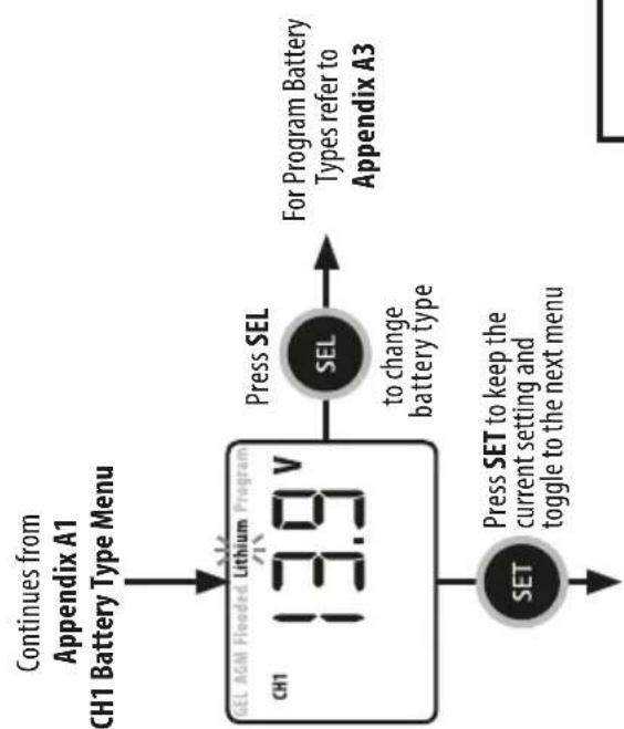
    A["Continues from Appendix A1\nCH1 Battery Type Menu"] --> B["GEL AGN Flooded Lithium Program\nCH1 13.9 V"]
    B --> C["Press SEL\nSEL\nto change battery type"]
    C --> D["For Program Battery Types refer to Appendix A3"]
    B --> E["SET\nPress SET to keep the current setting and toggle to the next menu"]

flowchart
graph TD
    A["CH1 LITHIUM BULK VOLTAGE"] --> B["CH1 Lithium 13.9V"]
    B --> C["Press SEL to enter Voltage Menu"]
    C --> D["CH1 Lithium 13.9V"]
    D --> E["Press SEL to change voltage (13.9V to 14.6V in 0.1V steps)"]
    E --> F["CH1 Lithium 14.6V"]
    F --> G["Press SEL to return to voltage"]

    H["CH1 LITHIUM FLOAT VOLTAGE"] --> I["CH1 Program 13.5V"]
    I --> J["Press SEL to enter Voltage Menu"]
    J --> K["CH1 Program 13.5V"]
    K --> L["Press SEL to change voltage (13.0V to 13.8V in 0.1V steps)"]
    L --> M["CH1 Program 14.2V"]
    M --> N["Press SEL to return to change voltage"]

    style A fill:#f9f,stroke:#333
    style H fill:#f9f,stroke:#333
    style I fill:#f9f,stroke:#333
    style K fill:#f9f,stroke:#333
    style M fill:#f9f,stroke:#333

flowchart
Ch1 Lithium Battery charging and battery termination flowchart, covering current setting, SEL, and voltage selection decisions.WARNING: FIRE HAZARD
When using the Lithium Battery type setting to set the battery charging parameters, please consult the battery manufacturer on all the voltage and current settings. Using the wrong setting to charge battery may overcharge, damage the battery and may cause a fire.
DC2DC+ €POWERcharger
Charger configuration is a simple step by step process as shown below. For Tech Support call Enerdrive on 1300 851 535 NOTE: The current setting below is based on the EN3DC40+ battery charger.

Appendix A3 PROGRAM MODE VERSION: REV. 1.00 - June 2017

flowchart
graph TD
    A["Continues from Appendix A2 CH1 Battery Type Menu"] --> B["SEL AGM Floeded Lithium Program CH1 13.8 V"]
    B --> C["Press SEL to change battery type"]
    C --> D["Back to Appendix A1 Battery Type"]
    B --> E["SET"]
    E --> F["Press SET to keep the current setting and toggle to the next menu"]
    F --> G["CH1 PROGRAM BULK VOLTAGE CH1 13.8 V"]
    G --> H["Press SEL to enter Voltage Menu"]
    H --> I["CH1 Program 13.8 V"]
    style A fill:#f9f,stroke:#333
    style I fill:#f9f,stroke:#333

flowchart
graph TD
    A["SET"] --> B["Program CH1 13.0V to enter Voltage Menu"]
    B --> C["SEL"]
    C --> D["Program CH1 13.0V"]
    D --> E["SEL"]
    E --> F["Program CH1 13.8V"]
    F --> G["SEL"]
    G --> H["To return to change voltage"]
    H --> I["SET"]
    I --> J["Program CH1 13.8V"]
    J --> K["SEL"]
    K --> L["To return to change current"]
    L --> M["SET"]
    M --> N["Program CH1 13.8V"]
    N --> O["SEL"]
    O --> P["To return to change current"]
    P --> Q["SET"]
    Q --> R["Program CH1 13.8V"]
    R --> S["SEL"]
    S --> T["To return to change current"]
    T --> U["SET"]
    U --> V["Program CH1 13.8V"]
    V --> W["SEL"]
    W --> X["To return to change current"]
    X --> Y["SET"]
    Y --> Z["Program CH1 13.8V"]
    Z --> AA["SEL"]
    AA --> AB["To return to change current"]
    AB --> AC["SET"]
    AC --> AD["Program CH1 13.8V"]
    AD --> AE["SEL"]
    AE --> AF["To return to change current"]
    AF --> AG["SET"]
    AG --> AH["Program CH1 13.8V"]
    AH --> AI["SEL"]
    AI --> AJ["To return to change current"]
    AJ --> AK["SET"]
    AK --> AL["Program CH1 13.8V"]
    AL --> AM["SEL"]
    AM --> AN["To return to change current"]
    AN --> AO["SET"]
    AO --> AP["Program CH1 13.8V"]
    AP --> AQ["SEL"]
    AQ --> AR["To return to change current"]
    AR --> AS["SET"]
    AS --> AT["Program CH1 13.8V"]
    AT --> AU["SEL"]
    AU --> AV["To return to change current"]

flowchart
graph TD
    A["CH1 Program BULK CURRENT"] --> B["SET"]
    B --> C["Press SET to keep the current setting and toggle to the next menu"]
    C --> D["SET"]
    D --> E["Press SET to keep the current setting and toggle to the next menu"]
    E --> F["CH1 Bulk Current "h" setting"]
    F --> G["SET"]
    G --> H["Press SET to keep the current setting and toggle to the next menu"]
    H --> I["CH1 Absorption to Float Current "L" Setting"]
    I --> J["SET"]
    J --> K["Press SET to keep the current setting and toggle to the next menu"]
    K --> L["CH1 Charge Mode"]
    L --> M["SET"]
    M --> N["Press SET to keep the current setting and toggle to the next menu"]
    N --> O["CH1 Display shows Charge Mode as currently set."]
    O --> P["Menu"]

    style A fill:#f9f,stroke:#333
    style I fill:#ccf,stroke:#333
    style L fill:#cfc,stroke:#333
    style F fill:#fcc,stroke:#333
    style G fill:#fcc,stroke:#333
    style H fill:#fcc,stroke:#333
    style J fill:#fcc,stroke:#333
    style K fill:#fcc,stroke:#333
    style I fill:#cff,stroke:#333
    style J fill:#cff,stroke:#333
    style L fill:#ffc,stroke:#333
    style M fill:#ffc,stroke:#333
WARNING: FIRE HAZARD
When using the Program Mode to set the battery charging parameters, please consult the battery manufacturer on all the voltage and current settings. Using the wrong setting to charge battery may overcharge, damage the battery and may cause a fire.
Fill in the details below for your reference and convenience.
Serial Number:
Date of Purchase:
Purchased From:
Notes:
Notes:
Notes:

Enerdrive
DRIVING YOUR ENERGY NEEDS
ENERDRIVE PTY LTD
P.O. Box 9159, Wynnum Plaza, Queensland, Australia 4178
Ph: 1300 851 535 / Fax: 07 3390 6911
Email: support@enerdrive.com.au
Web: www.enerdrive.com.au
- DC2DC+ €POWER charger
- Table of Contents
- Introduction 4
- Warnings 6
- PRODUCT DESCRIPTION 8
- UNDERSTANDING THE UNIT 9
- INSTALLING THE CHARGER
- CONNECTING THE CHARGER
- UNIT OPERATION
- INTRODUCTION
- Please Keep This Manual For Future Reference
- Disclaimer
- Important Note
- Product Numbers
- Service Contact Information ENERDRIVE PTY LTD
- Notice of Copyright
- Exclusions For Documentation And Product Usage
- WARNINGS
- Please read and follow the instructions and precautions carefully.
- CAUTION
- WARNING: Shock Hazard.
- Keep Away From Children!
- WARNING: Fire &/or Chemical Burn Hazard!
- LIMITATIONS OF USE
- WARNING
- Explosion Hazard!
- Failure To Follow These Instructions May Result In Death Or Serious Injury!
- PRODUCT DESCRIPTION
- UNDERSTANDING THE UNIT
- Multistage Charging Process - GEL, AGM, Flooded & Program Modes
- Lithium Charging Process
- Smart Charging Feature
- ePOWER charger algorithm
- Battery Bank Size Recommendation
- Before Installing The Unit Consider The Following:
- DO NOT INSTALL IN VEHICLE ENGINE BAY
- NOTE
- Mounting The Charger
- BEST PRACTICE
- This Charger SHOULD BE CORRECTLY GROUNDED.
- DC Output Wiring
- WARNING: Correct DC Wiring Is Required
- Recommended Cable Length, Size and Fuse Protection.
- Standard Temperature Sensor Connection
- Battery Wiring (Towing Applications):
- For Towed Applications i.e. Caravans, Camper Trailers
- Battery Wiring (Vehicle & Marine Applications):
- For In Vehicle & Marine Installation. i.e. Motorhomes, 4WD's & Trucks.
- Understanding The Charging Mechanism
- Note A:
- Note B:
- Note C:
- Note D:
- Maximising your Solar Harvest using the DC2DC+
- Understanding the Display & Function Keys during normal operation
- Understanding The Function Key 'MENU', 'SET' And 'SEL' During Charger Setting
- Digital Display:
- Automatic Override Functions:
- Programming Your Charger
- Understanding the Two-Stage (Mode 2) Charging (Default setting is 3)
- Understanding The Three-Stage (Mode 3) Charging
- Understanding The Battery Temperature Functions
- Battery Temperature Compensation:
- Procedure To Set Or View Charger Setting
- Procedure To Equalise Flooded Batteries
- DANGER
- Explosion Hazard And Risk Of Battery Damage.
- Risk of battery and equipment damage.
- Use the following procedure to setup the charger for battery equalisation.
- Understanding The Protection Features
- De-rating Charging Current:
- Over Temperature Shutdown:
- Battery Reverse Polarity:
- Charging A Flat Battery
- Understanding The Display Codes
- SPECIFICATIONS
- WARRANTY
- Year Limited Warranty
- Year Pro Rata Support Program
- Return and/or Repair Policy
- Limitations
- Appendix A1 LEAD ACID MODE VERSION: REV. 1.00 - June 2017
- DC2DC+ ePOWER charger
- DC2DC+ €POWERcharger
- Enerdrive
- ENERDRIVE PTY LTD
Brand : Enerdrive
Model : DC2DC+
Category : Battery charger