
FD525R - Security System OPTEX - Free user manual and instructions
Find the device manual for free FD525R OPTEX in PDF.


| Type of Product | Passive Infrared (PIR) Motion Sensor |
| Brand | OPTEX |
| Model | FD525R |
| Detection Technology | Pyroelectric Infrared Sensor |
| Maximum Detection Range | 12 m (40 ft) |
| Detection Angle | 90° |
| Power Supply | 12 - 24 V DC |
| Current Consumption | < 25 mA |
| Output | Relay (NC/NO) |
| Installation Type | Wall Mount |
| Dimensions (H x W x D) | 120 x 70 x 50 mm |
| Weight | 0.2 kg |
| IP Rating | IP65 |
| Operating Temperature | -20°C to 50°C |
| Material | ABS Plastic |
| Main Functions | Motion detection, adjustable sensitivity, tamper protection |
| Maintenance & Cleaning | Wipe with soft dry cloth; avoid solvents |
| Safety | Tamper switch, LED indicator, low voltage safety |
| Spare Parts & Repairability | Non-replaceable sensor element; mount bracket available |
| General Information | For outdoor use; compatible with most alarm panels |
Frequently Asked Questions - FD525R OPTEX
User questions about FD525R OPTEX
0 question about this device. Answer the ones you know or ask your own.
Ask a new question about this device
Download the instructions for your Security System in PDF format for free! Find your manual FD525R - OPTEX and take your electronic device back in hand. On this page are published all the documents necessary for the use of your device. FD525R by OPTEX.
USER MANUAL FD525R OPTEX
Fiber Defender FD525R™ User Manual
© Copyright 2015, Fiber SenSys® all rights reserved. No part of this publication may be reproduced or transmitted in any form or by any means, electronic or mechanical, including photocopy, recording, or any information storage and retrieval system, without permission in writing from Fiber SenSys®, Inc., 2925 NW Aloclek Drive, Suite 120, Hillsboro, Oregon 97124, USA.
This manual is provided by Fiber SenSys Inc. While reasonable efforts have been taken in the preparation of this material to ensure its accuracy, Fiber SenSys Inc. makes no express or implied warranties of any kind with regard to the documentation provided herein. Fiber SenSys Inc. reserves the right to revise this publication and to make changes from time to time in the content hereof without obligation of Fiber SenSys Inc. to notify any person or organization of such revision or changes.
FD525R ^TM , OM525 ^TM , RLM525 ^TM are trademarks of Fiber SenSys Inc. (FSI)
Fiber SenSys ^® is a registered trademark of Fiber SenSys Inc.
Windows ^® is a registered trademark of Microsoft Corporation.
Fiber SenSys Inc.
2925 NW Aloclek Dr.
Suite 120
Hillsboro, OR 97124
USA
Tel: 1-503-692-4430
Fax: 1-503-692-4410
info@fibersensys.com
www.fibersensys.com
Fiber SenSys
PERIMETER SECURITY
Table of contents
- Introduction ...... 4
- Safety Information 5
Safety Terms 5
Electrical Safety 5
Covers and Panels 5
Inspection 6
Laser Radiation....6
Fiber-Handling Precautions....6
FCC Rules 7
- The Sensing Fiber 8
Fiber Optic Sensing 8
Types of Installations 8
Connectors 9
System Configuration....9
- The Alarm Processing Unit (APU) 12
FD525R Rack-Mount APU Connections and Indicators 12
Optional Accessory Bus Modules....14
- Tuning the Zones 15
Start 500 Series View .... 15
APU Parameters Tab....15
HyperZone Tuning 17
Assigning a Device Name....20
Help Menu 20
The Realtime Tab 20
- Integrating the APU into the Security System 23
- Testing and Certification....24
-
Maintenance....25
-
Appendix A. Product Specifications....26
- Appendix B. Auxiliary Software Features....28
- Appendix C. Warranty Information....29
- Appendix E. Referenced Documents....30
1. Introduction
The FD525R alarm processing unit (APU) is a fiber optic sensor designed to detect potential intruders that are trying to breach a perimeter. The APU is capable of detecting multiple simultaneous disturbances along a protected perimeter. One APU can monitor up to twenty-five different sensing fibers (zones), with a maximum total perimeter of 5.8 kilometers (19,000 feet or 3.6 miles).
The FD525R detects intruders using a fiber optic sensor that is deployed on the perimeter. For perimeters with chain-link fencing, the fiber is installed inside conduit that is tied to the fence with stainless steel wire ties. The sensing fiber can also be deployed on decorative metal fences, cement walls, etc. The fiber optic sensor works by measuring modulated laser radiation that results from potential intruders who vibrate the structure to which the fiber is attached. When the FD525R detects intruders, it sends alarm messages to a head end, and can also switch relay contacts that can be used to manage lights, cameras, audible alarms, etc.
Because the fiber optic sensors use laser light which is intrinsically inert, the FD525R system can be installed safely at chemical or ammunition depots, or any location where the use of electricity is a concern. In addition, fiber optic technology is immune to EMI/RFI.
The remote capability of the FD525R APU allows the security system to be monitored from up to five kilometers away.
Figure 1-1 shows the front of the FD525R. The front of the APU has indicator lights that show the status of each zone; a steady green light indicates normal/secure operation, and red lights come on during an attempted intrusion (alarm), or if the fiber is cut (fault) On the right hand side there are LED indicators that show the status of the system; a steady green light indicates power, a yellow LED will flash when any of the zones are disturbed. Red lights come on during an intrusion (alarm), if the tamper monitor is triggered (tamper), if an accessory module has been damaged or disabled (ACC Bus Fault), or if the fiber is cut (fault).

Figure 1-1. FD525R APU.
2. Safety Information
This section contains information to help ensure safety and the proper operation of the equipment. Please follow these instructions carefully, and keep them accessible, for future reference. Whenever using the FD525R use only attachments and accessories that have been specified by FSI and refer all servicing to qualified personnel.
Safety Terms
The following icons may appear throughout this manual:

CAUTION: Identifies conditions or practices that could result in damage to equipment and/or loss/contamination of data.

WARNING: Identifies conditions or practices that could result in non-fatal personal injury.

DANGER: Identifies conditions or practices that could result in serious injury or death.
Electrical Safety
If the FD525R is damaged or malfunctions, disconnect power to the APU. Do not use the APU if any of the following conditions exist:
• The APU is damaged.
• The APU does not operate as expected.
- The APU has been subjected to prolonged storage under adverse conditions.
Do not put the APU into service until qualified service personnel have verified its safety.
Covers and Panels
There are no user-serviceable parts inside the APU. To avoid personal injury, do not remove any of the APU's covers or panels. The product warranty is void if the factory seal is broken. Do not operate the product unless the covers and panels are installed.
Inspection
The FD525R APU should be inspected for shipping damage. If any damage is found notify Fiber SenSys and file a claim with the carrier. Save the shipping container for possible inspection by the carrier.
Laser Radiation
The FD525R APU is a Class I laser product, as defined by IEC 60825-1 and CFR 21 subchapter J. A Class I laser emits insufficient light to constitute a hazard. However, avoid direct eye exposure to the output of this product or to the open end of any optical-fiber cable connected to this product.
The following stamp is found on the front panel of the FD525R APU:
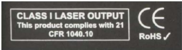
Figure 2-1. Class 1 laser stamp on front panel of the FD525R APU
Fiber-Handling Precautions

Warning: Optical fibers are made of glass and the ends of broken fibers can be sharp and may become lodged in the skin. Take appropriate handling precautions.
FCC Rules

Note: This equipment has been tested, and complies with the limits for a Class B digital device, pursuant to Part 15 of the FCC Rules. These limits are designed to provide reasonable protection against harmful interference in a residential installation. This equipment generates, uses, and can radiate radio-frequency energy. If the equipment is not installed and used in accordance with the instructions, it may cause harmful interference to radio communications. However, there is no guarantee that interference will not occur in a particular installation. If this equipment does cause harmful interference to radio or television reception, which can be determined by turning the equipment off and on, the user is encouraged to try to correct the interference by one or more of the following measures:
• Reorient or relocate the receiving antenna.
- Increase the separation between the equipment and receiver.
- Connect the equipment into an outlet on a circuit different from that to which the receiver is connected.
- Consult the dealer or an experienced radio/TV technician for help.
3. The Sensing Fiber
The FD525R detects intruders by sensing small disturbances caused by vibrations induced within a fiber optic sensor attached to the perimeter. The optical sensor is a thin strand of multimode optical fiber inside a specially designed 3 mm fiber optic cable. The fiber optic cable is installed in such a way that, when intruders attempt to cross the perimeter, they create slight vibrations that disturb the sensing fiber. These disturbances are then detected by the FD525R APU, which generates the appropriate alarm(s).
Fiber Optic Sensing
When an optical fiber is exposed to vibration, the vibrations cause small asymmetric changes in the fiber's density. In turn, these changes in density cause measurable changes in certain characteristics of laser light that is transmitted through the fiber. The FD525R uses precision lasers and detectors, along with sophisticated digital signal processing, to measure these changes in the laser radiation; analyzing them in order to determine whether they are caused by intruders or harmless nuisances such as vibrating equipment. To learn more about fiber optics and their use as sensors, refer to the fiber optics application note titled: AN-SM-007 Fiber Optics.
Types of Installations
Fenced Installation
There are many different ways to use the FD525R system. The most common installation is on chain link fence. For fence-mounted applications the fiber optic cable is installed inside a flexible conduit which is then secured to the fence using stainless steel wire ties. Other applications involve installing the optical cable inside the channels of decorative metal fence or running the flexible conduit (with optical cable inside) along the tops of concrete walls. For detailed information about the possible fenced perimeter installations and site design techniques see the application note on site design and assessment titled:
AN-SM-036 FD500 Series – Site Design and Assessment.
PDS and Network Security Installation
For a network security application, the FD525R provides protection against physical intrusion (such as tapping or sabotage) in a fiber optic network and can also be designed to physically protect copper data transmissions. The system works by utilizing existing (dark) fibers or newly installed fibers deployed inside of the cable raceway/conduit. The FD525R can “activate” dark multimode fibers and use them as sensors. These fiber optic sensors are capable of detecting the vibrations caused by an intruder as they attempt to breach the raceway/conduit or cut through the cable and physically attach to the fiber optic network.
For detailed information about the possible PDS and network security installations, and installation techniques, see the application note on installing network fiber optic cable titled: AN-SM-001 SecurLAN PDS.
Connectors
The FD525R is a time-domain-multiplexed system that can monitor up to 25 fully independent zones (sensing fibers) using a single APU. To maintain a high signal-to-noise ratio, it is important that all optical connections in the system be made with either fusion splices or angled physical-contact (APC) fiber optic connectors. PC and UPC connectors should not be used. For more information about fiber optic connectors, refer to the fiber optics application note: AN-SM-007 Fiber Optics.
System Configuration
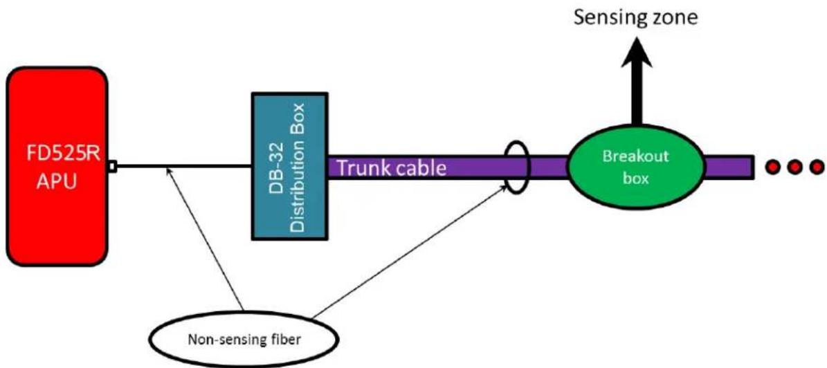
Typically, each zone consists of an insensitive lead-in fiber which connects to the sensing fiber ^1 . All sensing fibers used with the FD525R are “single ended,” so there is no need to loop the sensing fiber back to the APU. Instead, the far end of the sensing fiber is terminated with a special termination unit, called the Multimode End-Of-Line (MMEOL) terminator.
Fiber SenSys provides a trunk cable that can carry the insensitive lead-in fibers to all the zones for a single APU. At points where a zone is desired, specialized tools can be used to cut into the trunk cable to expose one of the insensitive lead-in fibers which is then spliced to sensing fiber (see figure 3-1); this technique is known as a “mid-entry.” The splice point is fully enclosed in a breakout box which serves as a splice enclosure and is sold as a complete kit, including the MMEOL. ^2 For more information on installing the trunk cable, sensors, and MMEOL, see the application note on installing perimeter fiber optic cable: AN-SM-035 FD500 Series – Standard Installation Instructions.
flowchart
graph LR
    A["FD525R APU"] --> B["DB-32 Distribution Box"]
    B --> C["Trunk cable"]
    C --> D["Breakout box"]
    D --> E["Sensing zone"]
    F["Non-sensing fiber"] --> B
Figure 3-1. Typical system configuration. The trunk cable holds the non-sensing fibers, and the breakout boxes act as splice enclosures for protecting the mid-entry points where the trunk cable is broken into when splicing the non-sensing lead-in fiber to the sensing fiber. The MMEOL is spliced onto the end of the sensing fiber. The three red dots indicate that the trunk cable continues on, to other breakout boxes and sensing fibers.
For more cost-sensitive applications, the FD525-HALO™ system can be deployed using a unified cable design (see figure 3-2). This system contains both the sensing fiber along with the insensitive trunk cables all integrated into one cable. The FD525-HALO™ system significantly reduces installation time and complexity. This system is appropriate for commercial, industrial, and government installations that require high security, but is not recommended for high-threat-level military applications because the sensitive zones of the unified cable are not cut tolerant. The FD525 can have the trunk cable buried or secured in metal conduit, and if a sensing fiber is cut then the cut zone will register a fault and all other zones will remain operational. If the FD525-HALO™ system has a sensing zone cut, all zones after that zone will register faults and will not be operational until the cable is repaired. For detailed installation information for the FD525-HALO™ system, refer to application note: AN-SM-037 FD500 Series - FD525-HALO™ Installation Instructions.

flowchart
graph LR
    A["525 APU"] --> B["DB4 distribution box"]
    B --> C["Unified Cable"]
    C --> D["Zone enclosures (up to 25)"]
    style A fill:#66ccff
    style B fill:#ffcccc
    style C fill:#66ccff
    style D fill:#66ccff
    note1["Insensitive lead-in cable"] --> A
    note2["Zone enclosures (up to 25)"] --> C
Figure 3-2. The FD525-HALO™ system significantly reduces installation time and complexity.
All zones must be properly installed and terminated before connecting to the APU. In addition, it is helpful to test the optical loss of each zone. Optical loss, however, must be tested before the termination units are installed on the ends of the zones (the termination units are not transmissive). Also, if using a DB-32, each zone should be numbered, and a label with the zone number affixed to the fiber near the connector that will plug into the DB-32. The non-sensing lead-in fibers plug directly into the APU, and are always connected with an angled SC connector (SC/APC).

Note: It is important that you only insert clean optical connectors into the APU's optical ports. Dirty connectors can degrade the performance of the APU, or even cause irreversible damage. When leaving connectors unconnected make sure they have protective caps installed on the ferrules. Caps protect the ferrule from damage that might be caused by bumping the ferrule against a foreign object, but caps can be dirty, and don't protect (effectively) against microscopic contamination. Consequently, be sure to clean all connectors prior to insertion into the alignment port, whether or not they have been capped. For more information on the care and cleaning of fiber optic connectors, refer to the fiber optics application note: AN-SM-007 Fiber Optics.
4. The Alarm Processing Unit (APU)
FD525R Rack-Mount APU Connections and Indicators

Figure 4-1. FD525R rack-mount APU front panel
The FD525R APU has the following control, connector, and indicators on the front panel:
- Test
Pushing the Test button performs a self-test, which causes the APU to temporarily activate all relays and LEDs to their alarm or fault states. When the button is released, all relays and LEDs resume normal communication of zone conditions.
The Test button is recessed so it cannot be inadvertently pushed. The Test button can be pressed using a small screwdriver or similar tool.
- USB port
The USB connection allows a PC to be connected to the APU to perform system configuration. In addition, this port can be used to monitor real-time event, alarm, and status signals.
• System status indicators
LED indicators show tamper, accessory bus fault, cable fault, alarm, event, and power status. The tamper, fault, and alarm LEDs are red; the event LED is yellow; and the power LED is green.
• Zone status indicators
Three LED status indicators for each zone in the system show zone status: Normal (green), Alarm (red), and Fault (yellow). Alarm and Fault LEDs both light up when there is a fault in a zone.

Figure 4-2. FD525R APU back panel without RLM525 module
The FD525R APU has the following controls and connectors on the back panel:
- Optical port
There are two SC/APC optical connectors that connect the APU to the fiber-optic cable assembly.

CAUTION: Any cable connected directly to the APU must have SC/APC connectors. Using the wrong type of connector can result in damage to the APU.
- TCP/IP port
An RJ45 connector is provided for TCP/IP network connection using an Ethernet cable. Use this connector to install the APU into a local-area network (LAN). Alarm and device-status data is sent between the APU and a networked control system using XML communication.
- ACC bus port
An RJ45 controller-area network (CAN) accessory bus port is provided for communication to and from a relay output module for integration with existing head-end equipment. Use this port to connect to an optional Fiber SenSys RLM525 relay module, or OM525 output module.
• Power connection and switch
90 to 250 VAC power connection is via a standard IEC recessed male receptacle. A North American power cord is supplied.
- Fuse
Inside the quarter-turn holder is a 3AG type fuse, rated for 1.25A and 250V.
Optional Accessory Bus Modules
The FD525R APU has no individual relay outputs per zone. Relay outputs and indicators for each zone can be added to the FD525R APU with an OM525 output module. Similarly, relay outputs for each zone can be added with an RLM525 relay module. Both modules act on alarm messages from the APU, activating the relays and indicators corresponding to the affected zones. These accessories can be located up to 25 feet (7.6 m) from the APU. For more information on these optional accessories, see the application note: AN-SM-025 500 Series Optional Accessories.
5. Tuning the Zones
The tuning software is called 500 Series View; it runs on a PC that is connected to the APU via the USB port on the front of the APU. 500 Series View is a Windows-based software application for system tuning and calibration; this software is used for maximizing sensitivity when detecting intrusions and minimizing nuisance alarms. 500 Series View can also be used for monitoring system performance, recording sensor data, and analyzing stored data.
Start 500 Series View
With power off to the APU, connect one end of a USB cable to the APU, and the other end to the PC from which you will be launching 500 Series View; then turn on power to the APU.
Launch the 500 Series View software by clicking on the software icon:

natural_image
Illustration of a magnifying glass over a set of yellow checkmarks on a blue background (no text or symbols)Upon launching the program, the APU is automatically detected and a connection is made. After connecting, 500 Series View starts up with the APU Parameters tab selected, and the screen displays the tuning parameters that are currently stored in the APU.
APU Parameters Tab
The parameters tab (see figure below) is where you:
- Define the tuning parameters for each HyperZone.
- Assign zones to HyperZones.
- Write parameters to the APU.
- Rename zones.
- Assign a device name to the APU.
- Define the XML report interval.

Figure 5-1. The 500 Series View AP Parameters screen
When tuning the APU, the parameters are assigned to HyperZones; each zone that is placed into a HyperZone is automatically given the tuning parameters of that HyperZone. In this way, HyperZones are a tool for making the tuning process easier; instead of individually entering the tuning parameters for each zone, the parameters can be altered by simply placing (dragging) that zone into the appropriate HyperZone (parent node).
Whenever making changes to the tuning parameters, the changes will not take effect until they are written to the APU. To write the new APU parameters to the APU, click the Write button, in the APU Parameter Control group.

CAUTION: When tuning a given HyperZone, do not select another HyperZone before clicking on the Write button. If you change HyperZones, or close 500 Series View, before saving the tuning parameters, all new parameters will be lost.
The number of HyperZones can be as high as 25 (in which case each zone is in its own HyperZone) or as low as one – in which case all the zones have the same tuning parameters.
When 500 Series View is first launched, all of the zones are contained within a single HyperZone. To create a new HyperZone, and place a zone into it, click on the APU Parameters tab and right click on the zone to be moved. Select the popup Add to new HyperZone when it appears. This will create a new HyperZone, and place the selected zone into it. When a new HyperZone is created, the parameters of the new HyperZone are identical to the parameters of the original until being changed by the user.
The process can be continued by right-clicking over other zones and creating additional HyperZones. Zones can be moved by dragging them and dropping them from one HyperZone tree to another.

Figure 5-2. Creating a new HyperZone
HyperZone Tuning
The tuning parameters are found in the lower right-hand corner of the 500 Series View APU Parameters screen. Generally, these tuning parameters will change from one HyperZone to the next. To change the tuning parameters, highlight the HyperZone either by double clicking it, or by right clicking on it and choosing Select from the pop-up menu (see figure 5-1).
With the HyperZone selected, change the value of any tuning parameter, using either the arrow keys, or by typing a new value into the associated box and pressing Enter. If the allowable range is exceeded, 500 Series View automatically changes the entry to the closest allowed value.
Each HyperZone has two virtual processors, and each processor can be individually tuned for a specific type of threat. For example, Processor 1 could be tuned to detect someone climbing over the fence, while Processor 2 might be tuned to detect someone cutting the fence.
The table below gives a brief summary of the tuning parameters that are available, and how they can be adjusted in order to maximize the probability of detection (PD), while minimizing the nuisance alarm rate (NAR). For detailed information about these tuning parameters, see the Fiber SenSys application note on tuning parameters titled:
AN-SM-008 Setting the Tuning Parameters.
| Parameter | Brief functional description |
| Processor | Activate the processor by checking the box next to it. Unchecking the boxes disables the processor. |
| Gain | Adjusts the signal amplitude, in dB. Although the effect is present, it is not visibly apparent in Realtime mode. Adjusts both processors simultaneously. |
| Sensitivity | Similar to GAIN, but the scale is linear, and the effect is visible in Realtime mode. Adjusts both processors simultaneously. |
| Prefilter | Defines a digital frequency filter. Applies to both processors. The Prefilter “Level” should not be confused with the “Signal Level,” “Signal,” or “Level” parameters used in other FSI products. |
| Wind Reject | Checking the box activates the wind-rejection software. Applies to both processors |
| Reject | Determines the amount of GAIN reduction during noisy conditions (to avoid nuisance alarms). Applies to both processors. |
| Signal | Sets a threshold that must be exceeded before an event is generated. This parameter is also called “Level” or “Signal Level” in other FSI products. |
| Low frequency | The APU ignores all signal content below this frequency. |
| High frequency | The APU ignores all signal content higher than this frequency. |
| Duration | Time interval during which the sensor signal must stay above the “Signal” threshold in order to qualify as an event. |
| Tolerance | A threshold for detecting long-lasting low-level signals that are not higher than “Signal.” |
| Event count | Number of events required to generate an alarm. |
| Event window | The time period that an additional event must occur after the previous one so that the event count accumulator increments; this period is used for the purpose of defining an alarm. |
| Event mask | Time threshold for ignoring events, for the purpose of defining an alarm. |
The tuning parameters can be saved for all HyperZones into a single file on a PC. This may be useful for restoring all system settings to the APU, or transferring them to another APU. To save and restore the settings, use the buttons in the File menu while in the APU Parameters screen.
To save calibration settings for all HyperZones, click on the File menu, and select the "Save settings" button. A Save As dialog box displays, requesting a file name and location. The file extension .prm is provided automatically. Enter the file information in the Save As dialog box and click OK. 500 Series View copies all parameters from each HyperZone and stores them in the designated file. The values read from the APU for the currently selected HyperZone are also displayed on the APU Parameters screen.

Figure 5-3. Filer operation buttons
To restore all APU settings, select the "Load settings" button. An Open dialog box displays. Select the correct .prm file and click OK. 500 Series View writes all parameter settings from the file to all HyperZones on the APU. This may take several seconds, depending on how many HyperZones are in the system. The values written from the file to the APU for the currently selected HyperZone are also displayed on the APU Parameters screen.
Assigning a Device Name
If your APU is installed in an existing local-area network, you can assign a unique device name to the APU that will be the name used to address the device in all XML messages.
Click on the Device Name field on the APU Parameters screen and enter the name. Click on the Write button to write the name to the APU.
Help Menu
Help is accessed from the menu at the top of the screen.

Figure 5-4. 500 Series View main Help menu
To view help in context, right click on any field on the screen to display a pop-up Help option, and left click on the pop-up. This displays the specific help text for that field.
The Realtime Tab
As a tuning aid, 500 Series View gives you the ability to view and record live signals from any zone. To use this function, click on the Realtime tab.
You can display real time data for any zone listed in the HyperZone tree by double clicking on the selected zone. 500 Series View pauses momentarily while establishing contact with the new zone, which is then highlighted. A progress bar in the lower right corner of the screen shows the display being updated in real time.
A status legend on the right-hand side of the screen shows alarms and events associated with Processors 1 and 2. Alarm indicators are shown in red and event indicators in yellow. Events and alarms are also shown as flashes across the Realtime window.
On the Realtime window, you can choose to view the sensor data in either Spectral mode or Time mode. In Spectral mode the display shows the sensor data as a function of frequency (see figure 5-5). In Time mode, the display shows sensor data as a function of time (see figure 5-6)

Figure 5-5. The 500 Series View Realtime screen
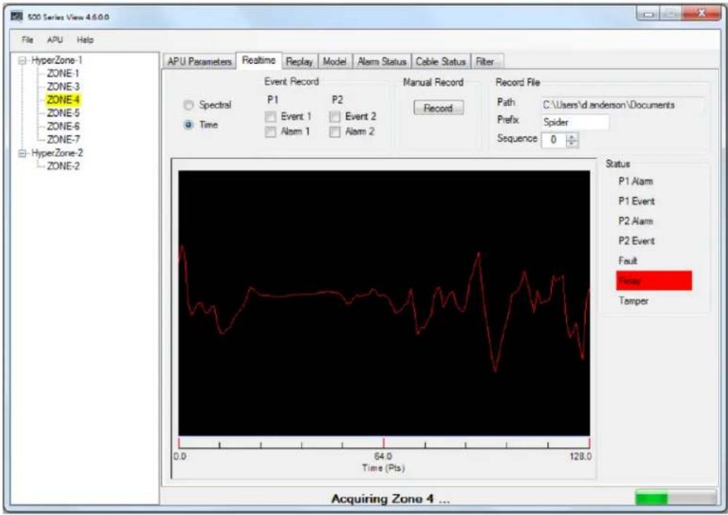
Figure 5-6. Realtime mode, showing data as a function of time (each sample point equals about 0.8 msec.)
For detailed information on the 500 Series Software Suite, refer to the software suite manual: PM-ENG-036 500 Series Software Suite User Manual.
6. Integrating the APU into the Security System
The FD525R APU is designed to be installed into a local-area network (LAN) and connected to a security head end, or other annunciator/monitoring equipment.
The FD525R communicates via XML (extensible markup language), sending status messages to the network such as alarm, tamper, and fault conditions. It can also receive device-configuration commands in XML format.
Processes involved in integrating the APU into a security system are described in detail in the networking application note, AN-SM-009 APU Networking.
7. Testing and Certification
System tuning is necessary when installing a new system, replacing an APU or after performing any system maintenance that involves changes to the cable assembly. Anytime the system is tuned, you should re-test it and verify that it meets all requirements for probability of detection and rejection of nuisance alarms. Other basic tests include:
Tamper test
If the tamper input on the FD525R APU is used, the connection should be tested by going to the tamper-protected enclosure, opening it, and verifying that the Head End records a tamper alarm (the tamper switch reports through the TCP/IP port like any other system alarm).
Fault test
The fault test verifies that a loss of optical power to a zone results in a cable fault indication for that zone, on the APU. To conduct this test, disconnect the optical fiber from the APU, and verify that the fault LED is illuminated (this LED is located on the front of the APU). Reconnect the fiber, and verify that the fault LED light goes off.
Probability of detection (PD)
PD performance testing begins with a review of the sorts of threats that need to be detected, simulating those threats, and measuring the probability with which the system detects them. To obtain a statistically significant sample, perform each threat simulation a minimum of 20 times in each zone.
For example, to determine the PD for an intruder climbing a fence, have a volunteer grab hold of the fence with both hands, and then climb/pull up the fence using both feet, until the beltline is even with the top of the fence. Have the climber drop or jump off the fence after climbing it. Perform the simulated intrusion at least 20 times while keeping track of the number of times the system triggers an alarm (count only one alarm per simulated intrusion).
Verify that the system triggers an alarm, as intended, with the required probability of detection. If the PD is too low, tune the system as described in section 5. Repeat this procedure for each installed zone on the secure perimeter.
Additional simulated intrusions might include cutting the fence, or digging/crawling beneath it.
8. Maintenance
Maintenance consists of routine inspections and periodic testing to verify the performance of the tamper and fault alarms, as well as the PD for simulated intrusions.
Visually inspect the FD525R APU at least every 90 days:
- Ensure the Power LED is illuminated and all alarm and fault LED indicators are normal.
- Check the optical connectors at the back of the APU, making sure they are not pinched or otherwise compromised.
On a periodic basis perform the tests described in section 7:
- Tamper.
- Fault.
• Probability of detection. - Relay function (if used).
There are no user-serviceable parts in the FD525R APU. In case of an APU failure, corrective maintenance involves replacing the APU. If you replace the APU or make changes to the fiber optic sensors, you must repeat the Port Assignment and Tuning processes described in sections 4 and 5.
To replace the APU, follow these steps:
- Ensure all current APU calibration parameters, as well as the system configuration data, have been saved to a PC file using the View software.
- Disconnect power to the APU, and then disconnect the optical fibers.
- Disconnect the Ethernet connection from the TCP/IP port, if present.
- Remove the APU and replace it with a new unit.
- Clean all the optical connectors per the procedures described in the fiber optics application note, AN-SM-007 Fiber Optics.
- Connect power to the new APU, and repeat the processes described in the chapters in this manual, on tuning, integration, and testing.
For troubleshooting assistance, contact Fiber SenSys Technical Support Service: telephone, 1-503-726-4455; email, support@fibersensys.com; or go to the Fiber SenSys website, www.fibersensys.com.
Appendix A. Product Specifications
| Alarm Processing Unit | |
| System type | Vibraon-sensing intrusion detecon system |
| Number of zones per APU | Up to twenty-ve fully independent zones. |
| APU power requirements | 90 to 250 VAC input17 was power consumpon (maximum)Fuse rang: 1.25 A |
| Communications | USB serial port for assigning zones to opcal ports, and for tuningTCP/IP port for alarm output and XML communicaonIndividual dry contact alarm and fault relays for each zoneDry contact alarm relay for tamper. |
| Contact rangsFault relay defaultAlarm relay defaultACC bus fault relay defaultDry Contact Resistance | 100 mA @ 24 VDC non-inducvenormally closedNormally open, and normally closedNormally closed7 Ω typical, 17 Ω max (Form A)5 Ω typical, 17 Ω max (Form B) |
| Network Port | Ethernet 10 Base-T/100 Base-TX (RJ-45) |
| Dimensions | Height = 8.81 cm (3.47 inch)Width = 48.16 cm (18.96 inch)Length = 42.52 cm (16.74 inch) |
| Operang temperature rangeOperang humidity range | 0°C to 55°C (32°F to 131°F)0 to 95% non-condensing |
| Compliance | CE, FCC Part 15, RoHS |
| Standard Cable Assembly | |
| Sensor conguraon | Fully independent zones, me-domain mulplexed through a mul-ber trunk cable and breakout boxes. |
| Sensing ber | Mulmode ber, custom manufactured to FSI specicaons |
| Insensitive lead-in ber | Single-mode ber, custom manufactured to FSI specicaonsMaximum length: 5km |
| Sensing Cable / Zone lengths3 | Sensing ber ≤ 800 m (2625.)For each zone, sensing ber + insensitive trunk cable ≤ 5.8 km (3.6 mi) |
| Trunk cable | Outside Plant type cable containing (minimum) one single-mode insensitive ber for each zone. |
| FD525-HALOTM Assembly | |
| Sensor conguraon | Fully independent zones, me-domain mulplexed through a mul-ber trunk cable and breakout boxes. |
| Unified cable | 1 mulmode ber with 5 single mode bers integrated into a rugged unified cable, custom manufactured to FSI specicaons |
| Insensitive lead-in ber | Single-mode ber, custom manufactured to FSI specicaonsMaximum length: 5km |
| Zone/cable lengths | Minimum distance between nodes: 20 m (65.6.)Maximum distance between nodes: 800 m (2625 ft.)Maximum cable length (not including insensitive lead-in): 5.8 km (3.6 mi) |
Appendix B. Auxiliary Software Features
There are several auxiliary software features available in 500 Series View that, although not used normally during installation, can be helpful in some circumstances. The table below summarizes these features and gives brief descriptions.
| Feature | Brief description |
| Saving and replaying Realtime data | This function captures the sensor signals caused by (for example) nuisance alarms. The data can then be analyzed and the analysis used to better tune out unwanted alarms. |
| Viewing and analyzing saved data | Allows for the import of saved data, which can be used to visually estimate how changes to the tuning parameters might affect the way the FD525R performs. |
| Model calibration data | Allows for theoretical calibration of the system parameters while previewing their effect on probability of detection and nuisance alarm rate. |
| View and log system activity | Displays the alarm status of all zones. Each zone is colored, based on its current alarm status. When the zone is in normal operation it is not colored. When the zone is in alarm, it is colored red, and when it registers an event it is colored yellow. If the zone is in fault, it is colored blue. |
| Perform system diagnostics | This mode allows for viewing of the signal level of each zone and comparing those levels with historical values saved in memory. Comparing historical values helps identify any zones where the fiber has been damaged, resulting in increased optical loss. |
| Using the digital filter | The FD525R has a specialized digital filter that is not available in other APUs. The filter is designed like a graphic equalizer, with 60 “slider bars” located across the frequency spectrum at 10 Hz intervals. This filter provides fine tuning of the FD525R’s frequency response. Modifiable through 500 Series View. |
| Display alarm history | This feature allows for the alarm history that was recorded on the Alarm Status screen to be displayed. In this way, one can quickly verify that the system is functioning properly after configuration and calibration. |
To see detailed information about each of these auxiliary software features, see the application note on FD525R auxiliary features, AN-SM-010 Auxiliary SW Features.
Appendix C. Warranty Information
Fiber SenSys warrants the FD525R APU to be free from electrical and mechanical defects in materials and workmanship for a period of two years from the date of shipment. This warranty does not apply to defects in the product caused by abuse, misuse, accident, casualty, alteration, negligent use of current or voltages other than those specified by Fiber SenSys, application or installation not in accordance with published instruction manuals, or repair not authorized by Fiber SenSys. This warranty is made in lieu of any other warranty either expressed or implied.
B. All returns will be tested to verify customer claims of non-compliance with the warranty described herein. If non-compliance is verified and is not due to customer abuse or the other exceptions described previously, Fiber SenSys will, at its option, repair or replace the FD525R APU returned to it, freight prepaid. Contact Fiber SenSys and obtain an RMA number prior to returning a product. Fiber SenSys will pay for ground return freight charges only. The Customer must pay for any other return shipping options.
C. Fiber SenSys liability is limited to the repair or replacement of the product only, and not the costs of installation, removal, or damage to user's property or other liabilities. If Fiber SenSys is unable to repair or replace a non-conforming product, it may offer a refund of the amount paid to Fiber SenSys for such product in full satisfaction of its warranty obligation. Maximum liability to Fiber SenSys is the cost of the product.
Appendix D. Referenced Documents
| AN-SM-001 SecurLAN PDS |
| AN-SM-007 Fiber Optics |
| AN-SM-008 Setting the Tuning Parameters |
| AN-SM-009 APU Networking |
| AN-SM-010 Auxiliary SW Features |
| AN-SM-025 500 Series Optional Accessories |
| AN-SM-035 FD500 Series – Standard Installation Instructions |
| AN-SM-036 FD500 Series – Site Design and Assessment |
| AN-SM-037 FD500 Series – FD525-HALOTM Installation Instructions |
| PM-ENG-036 500 Series Software Suite User Manual |

Note: It is possible to download these documents online from the Fiber Sensys web page: www.fibersensys.com
- Fiber Defender FD525R™ User Manual
- Fiber SenSys
- Table of contents
- Introduction
- Safety Information
- Safety Terms
- Electrical Safety
- Covers and Panels
- Inspection
- Laser Radiation
- Fiber-Handling Precautions
- FCC Rules
- The Sensing Fiber
- Fiber Optic Sensing
- Types of Installations
- Fenced Installation
- PDS and Network Security Installation
- Connectors
- System Configuration
- The Alarm Processing Unit (APU)
- FD525R Rack-Mount APU Connections and Indicators
- - Test
- - USB port
- • System status indicators
- • Zone status indicators
- - Optical port
- CAUTION: Any cable connected directly to the APU must have SC/APC connectors. Using the wrong type of connector can result in damage to the APU.
- - TCP/IP port
- - ACC bus port
- • Power connection and switch
- - Fuse
- Optional Accessory Bus Modules
- Tuning the Zones
- Start 500 Series View
- APU Parameters Tab
- HyperZone Tuning
- Assigning a Device Name
- Help Menu
- The Realtime Tab
- Integrating the APU into the Security System
- Testing and Certification
- Tamper test
- Fault test
- Probability of detection (PD)
- Maintenance
- Appendix A. Product Specifications
- Appendix B. Auxiliary Software Features
- Appendix C. Warranty Information
- Appendix D. Referenced Documents
Brand : OPTEX
Model : FD525R
Category : Security System