
RMCARD303 - Uncategorized CyberPower - Free user manual and instructions
Find the device manual for free RMCARD303 CyberPower in PDF.


| Product Type | Network Management Card |
| Model | RMCARD303 |
| Brand | CyberPower |
| Dimensions (W x D x H) | 130 x 100 x 30 mm |
| Weight | 0.3 kg |
| Power Supply | Powered by UPS via SNMP slot |
| Power Consumption | 2W typical |
| Network Interface | 10/100 Mbps Ethernet |
| Management Protocols | SNMP v1/v2c/v3, HTTP/HTTPS, Telnet/SSH |
| Compatible UPS Series | CyberPower PFC, PFC Sinewave, etc. |
| Environmental Monitoring | Temperature and humidity via external sensor |
| Alerts | Email, SNMP trap, SMS (with optional modem) |
| Logging | Event log, data log (CSV export) |
| Firmware Upgrade | Via web interface, TFTP |
| Maintenance | Clean with dry cloth; no liquid |
| Safety Certifications | FCC, CE, RoHS |
| Operating Temperature | 0°C to 40°C |
| Humidity | 0% to 95% non-condensing |
| Spare Parts | Not applicable (no user-serviceable parts) |
| Repairability | Not user-serviceable; contact support |
| Warranty | 2 years |
Frequently Asked Questions - RMCARD303 CyberPower
User questions about RMCARD303 CyberPower
0 question about this device. Answer the ones you know or ask your own.
Ask a new question about this device
Download the instructions for your Uncategorized in PDF format for free! Find your manual RMCARD303 - CyberPower and take your electronic device back in hand. On this page are published all the documents necessary for the use of your device. RMCARD303 by CyberPower.
USER MANUAL RMCARD303 CyberPower
Remote Management Card
RMCARD202 / RMCARD203
RMCARD302 / RMCARD303
User's Manual
Version 2.0
TABLE OF CONTENTS
Introduction ...... 1
Installation Guide 3
Web Interface 8
Reset to Default Setting/Recover from a Lost Password ..... 25
Firmware Upgrade 26
Troubleshooting 27
Appendix 1 28
Introduction
Overview
The CyberPower Remote Management Card allows for remote monitoring and controlling of a UPS attached to a network. After installing the hardware and configuring an IP address, the user can access, monitor, and control the UPS from anywhere in the world! Simply use a web browser such as Internet Explorer or Firefox to access your UPS. Servers and workstations can be protected by the UPS utilizing the PowerPanel® Business Edition Client version to gracefully shutdown when signaled by the Remote Management Card.
Features
• Real time UPS monitoring
- Remote management and configuration of UPS via Web Browser or NMS
- Trigger servers/workstations to shutdown during a power event to prevent data lose or corruption
Schedule shutdown/start-up/reboot of the UPS via remote control
• Event logging to trace UPS operational history
• Data logging for analyzing power conditions
- Save and restore configuration settings
• Event notifications via Email, SNMP traps, and SMS
• Support IPv4, TCP/IP, UDP, SNMPv1, HTTP, NTP, DNS, Telnet, DHCP, SMTP, FTP protocol
• Support IPv6, SNMPv3, HTTPS, SSH protocol (HW V2.0 above)
• Support Email Secure Authentication Protocols: SSL, TLS (HW V2.0 above)
CyberPower Remote Management System
Application
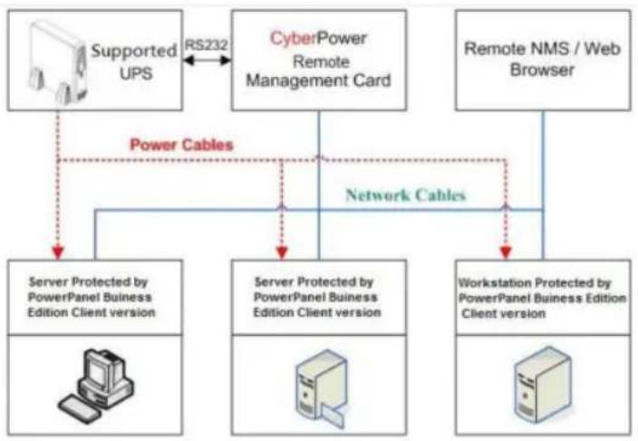
flowchart
graph TD
    A["Supported UPS"] -->|RS232| B["CyberPower Remote Management Card"]
    B -->|Power Cables| C["Server Protected by PowerPanel Buiness Edition Client version"]
    B -->|Network Cables| D["Server Protected by PowerPanel Buiness Edition Client version"]
    B --> E["Remote NMS / Web Browser"]
    C --> F["Workstation Protected by PowerPanel Buiness Edition Client version"]
    D --> F
    E --> F
Unpacking
Inspect the Remote Management Card upon receipt. The package should contain the following:
- CyberPower Remote Management Card
- PowerPanel® Business Edition CD with Software
- Quick Installation Guide
Installation Guide
Step 1. Hardware Installation
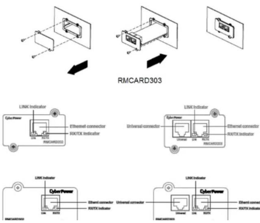
Internal smart slot Remote Management Card
- Remove the two retaining screws from the expansion port cover and remove the cover.
- Install the CyberPower Remote Management Card into the expansion port.
- Re-install and tighten the retaining screws.
- Connect the Ethernet cable to the Ethernet connector of the CyberPower Remote Management Card.
- (Optional) To connect with the environmental sensor, use a RJ45 Ethernet cable. Connect one end to the Universal port on the RMCARD and the other end into the sensor (RMCARD203/303). For further information, please refer to the ENVIROSENOR user's manual.
Note: The CyberPower Remote Management Card is a hot-swap device, so you do not need to turn off the UPS to install it.
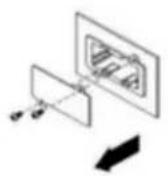
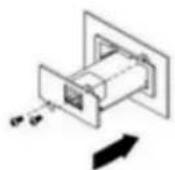
RMCARD202
CyberPower Remote Management System
Step 2. Configure the IP address for the CyberPower Remote Management Card
Method 1: Using the Power Device Network Utility Tool
- Install the Power Device Network Utility tool available for download on the Network Power Management product web page at www.CyberPower.com or from the included CD. It is located on the CD in the \tools\network folder. Double click the "Power Device Network Utility" installation file, "Setup.exe" to begin the installation.
- After installation completes, run the "Power Device Network Utility" (Under "All Programs", select "CyberPower Power Device Network Utility").
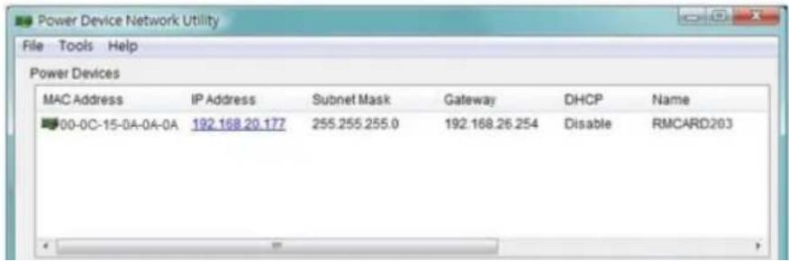
- The main dialog of the Power Device Network Utility Tool program is shown in Figure 1. The configuration tool will display all CyberPower Remote Management devices present on the same network subnet. The "Refresh" button is used to search the local network subnet again.
CyberPower Remote Management System
- You can modify the IP Address, Subnet Mask, and Gateway address for the Device MAC Address listed in the Device Network Settings window, as shown in Figure 2. The default IP Address is 192.168.20.177 and the default Subnet Mask is 255.255.255.0.
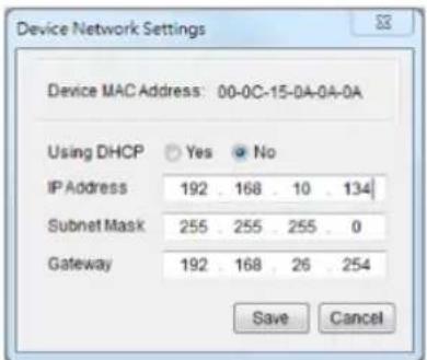
Figure 2. The Device Network setting window.
- Modify the IP, subnet mask or gateway address. Enter the new addresses into the corresponding fields.
-
You will need to enter a User Name and Password for the Remote Management Card in the authentication window, as shown in Figure 3.
-
Default user name: cyber
- Default password: cyber
CyberPower Remote Management System
- If the IP address change is successful, you will see a message confirming the IP set up is OK, as shown in Figure 4.
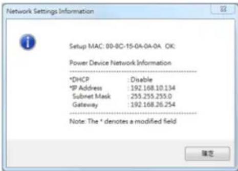
Figure 4. Setup IP Address successfully message.
Method 2: Using a command prompt
- Obtain the MAC address from the label on the Remote Management Card. Each Management Card has a unique MAC address.
Note: The MAC address is labelled on the card.
- Use the ARP command to set the IP address.
Web Interface
Login User Account
You will need to enter a User Name and Password to login to the interface. There are two user account types.
-
Administrator
-
Default user name: cyber
-
Default password: cyber
-
View only
-
Default username: device
- Default password: cyber
The administrator can access all functions, including enable/disable the view only account. The viewer can access read only features but cannot change any settings.
Note: 1. The Administrator account is also used for the FTP log in and authentication check in the Power Device Network Utility.
- The Login process uses MD5 algorithm to protect the username and password.
Web Content
[Summary] Provide an overview of the system operation and the items that are auto refreshed; However, different model of RMCARD may have different items displayed.
| Current Condition | Display the current operating condition of UPS and environment sensor. |
| UPS Status | |
| Battery Capacity | The percentage of the current UPS battery capacity in a graph. |
| Load | The load of UPS as a percentage of available Watts in a graph. |
| Remaining Runtime | How long the UPS can support its load by battery power. |
| System Data | |
| Name | The name of the equipment. |
| Location | The Location of the equipment. |
| Contact | The person to contact about this equipment. |
| Uptime. | How long the system has been working continuously |
| Envir | |
| Temperature | The current temperature of the environment in a graph. |
| Humidity | The current humidity of the environment in a graph. |
| Envir Data | |
| Name | The name of the environment sensor. |
| Location | The location of the environment sensor. |
| Recent Device Events | List the latest 5 events that occurred recently. |
CyberPower Remote Management System
[UPS] Following items can be displayed/configured through the UPS page; however, different UPS may have different items displayed/configured.
[UPS->Status] Display the basic information about the current UPS status and the items are auto refreshed.
| Item | Definition |
| Input | |
| Status | Display the present status of the utility power supplied to the UPS. |
| Voltage | The current input voltage of the utility power. |
| Frequency | The current frequency of the utility power supplied to the UPS. |
| Output | |
| Status | Display the present status of the output power the UPS is supplying to connected equipment. |
| Voltage | The output voltage the UPS is supplying to the connected equipment. |
| Frequency | The output frequency the UPS is supplying to the connected equipment. |
| Load | The percentage of the total UPS capacity that is being supplied to the connected equipment. This is displayed as Watts in some UPS models. |
| Non-Critical Bank | Display the present status of the NCL outlet. |
| Battery | |
| Status | Display the present status of the battery packs. |
| Remaining Capacity | The percentage of the current UPS battery capacity. |
| Remaining Runtime | How long the UPS can support its load under battery mode. |
CyberPower Remote Management System
[UPS->Information] Provide the technical specifications of the connecting UPS.
| Information | Description |
| Model Name | The model name of the UPS. |
| Voltage Rating | The output voltage rating (Volts) of the UPS. |
| Working Frequency | The output frequency rating (Hz) of the UPS. |
| Power Rating | The Volt-Amp rating of the UPS. |
| Current Rating | The output current rating (Amps) of the UPS. |
| Load Power | The power rating (Watts) of the UPS. |
| Battery Voltage Rating | The DC voltage rating of the battery set. |
| Firmware Version | The version number of the UPS firmware. |
| USB Version | The version number of the UPS USB firmware |
| LCD Version | The version number of the UPS LCD firmware |
| Battery Replacement Date | The date that the batteries were last replaced. This must be set manually and should be set after the batteries have been replaced or when the unit is first installed. If this date has not been set, it is recommended that this date should be set immediately. |
| Non-Critical Bank | The amount of the Non-Critical Load. |
| External Batteries | The amount of the external battery packs connected to the UPS. |
| Installation Place | When clicking the “Find it” button, either the alarm will beep or the indicators will flash to inform users of the location. This helps users to identify a specific UPS in a multiple UPS installation. |
CyberPower Remote Management System
[UPS->Configuration] Configure the parameters of the UPS.
| Item | Definition |
| Supplied Power | |
| Voltage | Set the output voltage which is supplied to the connected equipment. |
| Utility Power Failure Condition | |
| High/Low Input (or Output) Voltage Threshold | When the utility power voltage or output voltage (according to the UPS support) is higher/lower than the threshold, the UPS will supply battery power to the connected equipment. This setting only comes into effect after a restart of the UPS. |
| Frequency Tolerance | Sets the acceptable range of the input frequency. It will be in power failure condition if out of this tolerance. |
| Operation | |
| Normal | Normal working mode of the UPS. |
| Generator Mode | If the UPS uses generator as its input power, this option should enable the UPS to function normally. If this option is selected, the UPS will be forbidden to enter Bypass mode or ECO mode to protect the powered equipment. |
| ECO Mode | On-line UPS enters Economy mode. The UPS will enter Bypass mode when the input voltage/frequency is in the range of thresholds. Once the utility voltage/frequency exceeds thresholds, the UPS will supply power to its load. |
| Manual Bypass | Determine whether to allow the UPS to enter Manual Bypass mode. If this option is selected, the UPS will be forced to enter Bypass |
CyberPower Remote Management System
| Power Restore | After utility power is restored, the UPS turns on automatically and supplies power to the computer. If the computer BIOS is set to boot when power restores, the computer will restart automatically. The following settings are used to configure the UPS restore actions: |
| Recharged Delay | When utility power is restored, the UPS will start to recharge after the specified delay is expired. |
| Recharged Capacity | When utility power is restored, the UPS will start to recharge after the specified battery capacity is met. |
| Returned Delay | When utility power is restored, the UPS will delay the restoration of output power. This option can be used to stagger the startup time of multiple UPSs to avoid overloading the utility power circuit or power source. The Returned Delay will take effect every time when the UPS restores power. This also includes the scheduling and user controlling task. |
| Battery | |
| Low Battery Threshold | When the UPS supplies battery power and the remaining capacity is lower than this threshold, the UPS will alarm. |
| External Battery Pack | Set the amount of external battery packs. This allows for an accurate runtime estimation based upon the total number of batteries. |
| System | |
| Cold Start | Set the ability of the UPS to start in the absence of input power. When this option is enabled, the UPS can be turned on without input power. |
| Audible Alarm | If this option is enabled, the UPS will issue an audible alarm when |
CyberPower Remote Management System
| Wiring Fault Detect | If this option is enabled, the UPS will detect if the UPS wiring is not grounded or is reversed. It is recommended to assure the UPS wiring has ground connection first. This option should be enabled if the UPS wiring has ground connection. |
| Non-Critical Outlet Bank | |
| Turn Off Threshold | When supplying battery power, the UPS will power off the NCL outlet if the remaining battery capacity is lower than this threshold. |
| Turn off Delay Time | When supplying battery power, the UPS will power off this NCL outlet after this delay time is met. |
| Turn On Delay Time | When utility power is restored, the UPS will restore the output of the NCL outlet after the delay time is met. This prevents excessive power consumption caused by all the connected equipment rebooting at the same time. |
[UPS->Master Switch] Switch the output power of the UPS to be on or off.
| Item | Definition |
| Reboot UPS | Turn the UPS off and back on |
| Turn UPS Off | Turn the UPS off. |
| UPS Sleep | This command is available under Utility Power Failure Mode. It will make UPS under sleep mode until power is restored. |
| Cancel Switch | Cancel a pending action to turn the UPS off. |
| Turn UPS On | Turn the UPS on. |
| Shutdown/Sleep Delay | How long the UPS waits before it turns off in response to a "Reboot UPS", "Turn UPS off" or "UPS Sleep" command. |
CyberPower Remote Management System
[UPS->Diagnostics] When a power failure occurs, the UPS will supply battery power to all connected equipment immediately. The UPS must have sufficient runtime for all connected computers to be shut down properly.
The UPS/Diagnostics page provides the information to verify if the UPS has sufficient battery runtime for the connected computers to shutdown properly. Perform a complete runtime calibration to ensure an accurate estimate of the runtime for the connected load.
Battery Test
The Battery Test will force the UPS to switch to battery power for 10 seconds. This allows the user to verify the battery conditions and provides information about the battery, including the results and date of the last battery test. Click the "Initiate" button to begin a battery test.
Performing a battery test is prohibited when the Frequency Working Mode option is set to fixed. If performing a battery test on the fixed frequency mode, a UPS fault may occur and cause the UPS to enter Bypass mode. The frequency on Bypass mode may not be accepted and may damage the connected equipment.
The results will be reported after a battery test completes.
- Last Test Date: The date the last battery test was performed.
- Last Test Result: The results of the last battery test.
Passed: The battery performs normally during the test.
None: The UPS has never performed the battery test.
Failed: The battery test results in failure.
Follow the steps below if the battery test fails:
CyberPower Remote Management System
• Estimated Runtime: The estimated runtime of the batteries.
• Last Calibration Elapsed Time: The elapsed time of last Runtime calibration.
• Last Calibration Result: The results of the last runtime calibration.
Passed: The runtime calibration is completed and the batteries are good.
None: The UPS has never performed a runtime calibration.
Failed: The UPS fails during the runtime calibration.
Canceled: The calibration was interrupted.
• Last Calibration Date: The last date performing the runtime calibration.
Note: 1. It is recommended to perform at least one calibration every 3 months.
- A complete calibration causes the battery capacity to deplete. Ensure the UPS has recharged completely after performing a calibration.
[UPS->Schedule]: Sets the UPS to automatically shutdown and restart at scheduled times (one time/per day/per week). The Schedule page manages scheduled shutdowns and lists all configured schedules. Each schedule row displays the details of when the schedule will take effect and when to perform it.
[One Time]: The user may set a specific date and time for the UPS shutdown.
[Per Day]: Set a specific time of the day for the UPS shutdown.
[Per Week]: Set a specific day and time of the week for the UPS shutdown.
- Click [One Time], [Per Day] or [Per Week] option and Click "Next>>", Enter the date and time to shut down the UPS. Select [Never], [Immediately], or the date and time for the UPS to restore power. Select the bank to be controlled, and click "Shutdown Clients" to set all clients to perform a graceful shutdown. You can enter a comment for this Schedule.
CyberPower Remote Management System
[Envir->Status] Display the basic information of the environmental sensor and connected devices.
| Item | Definition |
| Information | |
| Name | The name of the environment sensor. |
| Location | The location of the environment sensor. |
| Temperature | |
| Current Value | The current temperature of the environment. |
| Maximum | The highest temperature as well as the time of occurrence detected by the environment sensor. |
| Minimum | The lowest temperature as well as the time of occurrence detected by the environment sensor. |
| Humidity | |
| Current Value | The current humidity of the environment. |
| Maximum | The highest humidity as well as the time of occurrence detected by the environment sensor. |
| Minimum | The lowest humidity as well as the time of occurrence detected by the environment sensor. |
| Contact | Display the name and status (Normal/Abnormal) of contacts. |
[Envir->Configuration]
| Item | Definition |
| Information | |
| Name | The name used to identify the environment sensor. |
| Location | The place where the environment sensor is located. |
CyberPower Remote Management System
[Logs->Event Logs] Display the list of events and a brief description of each event along with the date and time stamp.
Note: 1. The recordable events are listed under "System->Notifications->Event Action."
- The recorded time is using the 24-hour clock format.
[Logs->Status Records] This page is used to view the logs of the UPS status and environment status; however, different product may have different items displayed.
All items have the same definition as they are in the UPS status or environment status.
• Input min (V): The minimum input voltage of the utility power from the previous record.
• Input max (V): The maximum input voltage of the utility power from the previous record.
• Input (Hz): The current frequency of the utility power supplied to the UPS.
• Output (V): The output voltage of the UPS supplying to the connected equipment.
• Output (Hz): The output frequency of the UPS supplying to the connected equipment.
- Load (%): The percentage of the total UPS power load supplying to the connected equipment.
• Capacity (%): The percentage of the current UPS battery capacity.
• Remaining Runtime: How long the UPS can support its load under battery mode.
• Temperature: The current temperature of the environment.
• Humidity: The current humidity of the environment.
[Logs->Graphing] This page is used to diagram the data of the Status Record. The graphing function makes the status records easier to be analyzed.
| Item | Definition |
| The period used to draw the graph backward from today. The longer |
CyberPower Remote Management System
[Logs->Maintenance] This page is used to maintain "Event Logs" and "Status Records". The application provides information on how many events have been recorded before it is full.
| Item | Definition |
| Event Logs | |
| Clear All | Clear the existing event logs. |
| The Number of Events | The number of existing event logs/the max number of event logs. |
| Save Event Logs | Save the existing event logs as a txt file. |
| Status Records | |
| Recording Interval | Set the frequency to record the status data. A smaller interval will provide more frequent recordings but maintain them for a shorter period. A larger interval will provide less frequent recordings, but maintain them for a longer period. |
| Clear All | Clear the existing status records. |
| Remaining Time | The remaining recordable time base on the recording interval. |
| Save Status Records | Save the status records as a txt file. |
Note: Some old event logs/status records will be cleared automatically when there is no space to record.
[System->General->User Account] This page is used to configure the login account.
| Information | Description |
| Administrator | The administrator can access full function, including enable/disable the Viewer account. |
| Viewer | The viewer can access the read function but cannot control or |
Change Viewer account:
- Select "Allow Access" to enable the Viewer account
- Enter the User Name
- Set the Manager IP (optional)
- Enter New Password
- Enter Confirm Password
- Click "Apply"
[System->General->Date & Time] Current Settings: Displays the current date and time on the card and allows users to set the date and time. To set the date and time, users can choose to set manually or by using the NTP (Network Time Protocol) server.
System Time Configuration:
Choose the Time Zone off your location first, and
- Using NTP server: Enter the IP address/domain name of NTP servers, choose the time zone, and set the frequency to update the date and time from NTP server. Choose "Update right now" to update immediately.
- Manual Setup: Enter the date and time in the designated format.
[System->General->Daylight Saving Time] Adjust the clock daylight saving time (HW V2.0 above).
| Item | Definition |
| Disable | Disable DST . |
| Tradition US DST | Start at 2:00a.m. on the second Sunday in March; End at 2:00a.m. on the first Sunday in November. |
| Manual DST | Manual DST date time rules. |
[System->General->Identification] Assign the system's name, contact, and location.
| Item | Definition |
| Name | The name of the equipment. |
| Contact | Where the power equipment is located. |
| Location | The person to contact about this equipment. |
[System->General->Security] Set for security setting.
| Item | Definition |
| Timeout | The period (in minutes) that the system waits before auto logging off |
| Secret Phrase | The Authentication Phrase used to communicate with PowerPanel Business Edition Client. |
CyberPower Remote Management System
[System->Network Service->TCP/IPv4] Display the current TCP/IP settings: IP address, Subnet Mask, Gateway, and DNS server. This also provides the function to obtain TCP/IP settings from the DHCP server.
- DHCP: Select the "Enable DHCP" option and click "Apply" to get IP address, Subnet Mask, and Gateway by DHCP. Select the "Obtain DNS Address from DHCP" option and click "Apply" to get the IP of DNS from the DHCP.
- Manual: Enter the TCP/IP settings directly and click "Apply".
[System->Network Service->TCP/IPv6] Display the current the IPv6 settings (HW V2.0 above).
• IPv6 Interface: Displays the current IPv6 address.
• IPv6 Gateway: Displays the current IPv6 gateway.
• IPv6 Configuration:
- Allow Access: Set the IPv6 service to either Enable or Disable.
- Router Control: The IPv6 address is assigned through the method (Stateless Address Auto-configuration, Stateless DHCPv6 or Stateful DHCPv6) which is decided by router setting.
• Manual: The IPv6 address is assigned by manual setting.
- Manual IPv6 Address: Enter the IPv6 address directly and click "Apply" when the Manual box is checked.
[System->Network Service->SNMPv1 Service] Allow users to select the NMS, defined by the IP settings that can use the channel to control the system data access through SNMPv1 Service.
| Item | Definition |
| Allow Access | Set the SNMP service to either Enable or Disable. |
CyberPower Remote Management System
[System->Network Service->SNMPv3 Service] Allow users to enable/disable SNMPv3 service and configure the parameters of accessing through SNMPv3 service (HW V2.0 above only).
| Item | Definition |
| Allow Access | Set the SNMPv3 service to either Enable or Disable. |
| User Name | The name to identify SNMPv3 user. The field must be 1 to 31 characters length. |
| Authentication Password | The password used to generate the key used for authentication. The field must be 16 to 31 characters length. |
| Privacy Password | The password used to generate the key used for encryption. The field must be 16 to 31 characters length. |
| IP | The IP address or IP address mask can be accessed by NMS. A specific IP address allows access only by the NMS with the specified IP Address. The 255 is regarded as the mask and the rules list as follows:192.168.20.255: Access only by an NMS on the 192.168.20 segment.192.255.255.255: Access only by an NMS on the 192 segment.0.0.0.0 (the default setting) or 255.255.255.255: Access by any NMS on any segment. |
| Authentication Type | The hash type for authentication. |
| Privacy Type | The type for encrypting and decrypting data. |
[System->Network Service->Web Service] Select Enable to allow access to the HTTP or HTTPS Service and configures the TCP/IP port for them. Use the "Valid Certificate" to browse the detailed
CyberPower Remote Management System
[System->Network Service->FTP Service] Allows users to Enable/Disable the FTP server service and configure the TCP/IP port of the FTP server (21 by default).
Note: The FTP server is used for upgrading Firmware. For more details about the upgrade process, please refer to "Firmware Upgrade" section.
[System->Notifications->Event Action] Display the event actions for each event. Users can click on the event to modify its action. When a specific event happens, the user can be notified by the corresponding method according to this list.
• Log: Record the event in the "Event Logs".
• E-mail: Send an email to a specific user (An available SMTP server is necessary).
- Trap: A SNMP trap sent to a specific IP address.
- SMS: Send a short message to a specific mobile phone number (An available SMS service provider is needed).
[System->Notifications->SMTP Server] After setting the proper SMTP server, the UPS can send an email to users when a specific event occurs.
| Item | Definition |
| Server's IP/Host Name | The IP or Host Name of SMTP server used to notify users by E-mail. |
| Sender's E-mail Address | The context of From field shown in the e-mail message sent to user. |
| Authentication | Select this option if the SMTP server needs Authentication check. |
| Username | Username used for Authentication. |
| Password | Password used for Authentication. |
CyberPower Remote Management System
[System->Notifications->SMS Service] Short Message Service (SMS) is a communication service used by mobile communication systems. Using standardized communication protocols will allow the interchange of short text messages between mobile devices. The system provides 4 methods to users to choose how they want to send the messages.
| Information | Description |
| Service provider is Clickatell | Select the Clickatell option in the SMS Method field. Complete all the account details including Username, Password and HTTP API ID fields. |
| Service provider accepts HTTP GET | This specification from the SMS provider is required before using the HTTP GET method. Select the Using HTTP GET option in the SMS Method field. Insert the E_PHONE_NUMBER as recipient's mobile phone number and the E_PHONE_MESSAGE as event message, describe in the specification, and fill in the URL field. The expressions will be replaced by relevant content before the Client sends a notification to SMS provider. |
| Service provider accepts HTTP POST | This specification from the SMS provider is required before using the HTTP POST method to deliver messages to SMS providers. Select the Using HTTP POST option in the SMS Method field. Insert E_PHONE_NUMBER as recipient's mobile phone number and E_PHONE_MESSAGE as the event message, describe in the specification, and fill in the POST URL and POST BODY fields. The expressions will be replaced by the relevant content before the Agent/Client sends a notification to the SMS provider. |
| This specification from a SMS provider is required before using the |
CyberPower Remote Management System
[System->Reset/Reboot] Reset or reboot the UPS.
| Item | Definition |
| Reboot RMCARD | Restart the RMCARD without turning off and restarting the UPS. |
| Reset RMCARD | Reset the RMCARD to default setting and restart it. This action will not turn off or restart the UPS. |
| Reset RMCARD (TCP/IP Settings Reserved) | Reset the RMCARD to default setting but reserving TCP/IP settings, and restart it. This action will not turn off or restart the UPS. |
[System->About] Display vital information for the Remote Management Card.
| Item | Definition |
| Model Name | Model name of the Remote Management Card. |
| Firmware Version | The version number of the current firmware installed on Remote Management Card. |
| Firmware Updated Date | The date the firmware was last updated. |
| Hardware VersionMAC Address | The hardware version of the Remote Management Card.MAC address of the Remote Management Card.Note: The MAC address is also listed on the bottom of the Remote Management Card. |
| Save Configuration | Click “Save” to save the configuration to local PC. The text file will have a default format of YYYY_MM_DD_HHMM.txt. |
| Restore Configuration | Use this function to restore a configuration that has been saved earlier. Click “Browse” to the location of the saved configuration file and click “Submit”. |
Reset to Default Setting / Recover from a Lost Password
To reset the CyberPower Remote Management Card to its default setting (including WEB log-in user name and password), please use the following steps:
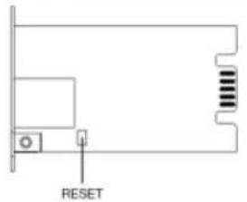
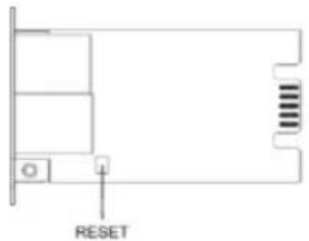
RMCARD202
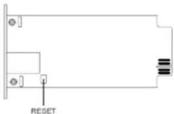
RMCARD302
RMCARD203
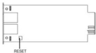
natural_image
Pure electrical circuit lines without any symbolsRMCARD303
Firmware Upgrade
By upgrading the Firmware, you can obtain both the new features and updates/improvements to existing functionality. There are two files to update in order to upgrade the firmware version.
RMCARD202/RMCARD203 upgrade files:
HW V2.0
HW V1.0
- A. cpsrm2sbfw_XXX.bin
- A. cpssnmpfw_XXX.bin
- B. cpsrm2sbdata_XXX.bin
- B. cpssnmpdata_XXX.bin
RMCARD302/RMCARD303 upgrade files:
HW V2.0
HWV1.0
- A. cpsrm3sbfw_XXX.bin
- A. cpsrm302afw_XXX.bin
- B. cpsrm3sbdata_XXX.bin
- B. cpsrm302adata_XXX.bin
Use the following steps to upgrade the firmware:
- Download the latest Firmware
- Extract the file to "C:\"
- Open a command prompt window
- Login to the CyberPower Remote Management Card with FTP command, type
(1) ftp
(2) ftp> open
(3) To [current ip of RMCARD] [port]; EX: To 192.168.22.126 21
(4) Input USER NAME and PASSWORD (same as the administrator account in Web interface
Troubleshooting
| Item | Definition |
| Problem | Solution |
| Unable to configure the Remote Management Card by method 1 or method 2 in user's manual | 1. Check the LED status, the condition is normal when the yellow and green LEDs are both on.If green LED is off :▶Check if the Remote Management Card is properly seated in the UPS and the UPS power is connected to working electrical outlet.If yellow LED is off :▶Ensure the network connection is good.2. Ensure the PC being used is on the same network subnet as Remote Management Card.3. Ensure the Jumper on the Reset Pin is correctly installed. |
| Unable to ping the Remote Management Card | 1. Use method 1 and method 2 in user's manual to get/set a correct IP address for the Remote Management Card.2. If the PC being used is on a different network subnet from the Remote Management Card, verify the setting of subnet mask and the IP address of gateway. |
Appendix 1
IP Address Settings for CyberPower Remote Management Card
Overview
All devices on a computer network need to have an IP address. Each device's IP address is unique. The same address cannot be used twice. In order to assign an IP address to the CyberPower Remote Management Card, you must determine the range of the available IP addresses, and then choose an unused IP address to assign to the Remote Management Card.
Note: You may need to contact your network administrator to obtain an available IP address.
Procedures to find an IP address:
1. Locate the subnet of CyberPower Remote Management Card.
One way to determine the range of possible IP addresses is to view the network configuration on a workstation. Click on [Start] and select [Run]. Type "command" into the open box and click [OK]. At the command prompt type "ipconfig /all" and press [Enter]. The computer will display network information as listed below:
Ethernet adapter
Connection-specific DNS Suffix.....: xxxx.com
Description.....: D-Link DE220 ISA PnP LAN adapter
Physical Address.....: 00-80-C8-DA-7A-C0
DHCP Enabled.....: Yes
Autoconfiguration Enabled · Yes
CyberPower Remote Management System
2. Select an IP Address for CyberPower Remote Management Card
Verify the IP Addresses for the computer and the Remote Management Card belong to the same subnet. Refer to the above network information, the possible IP Address for the Remote Management Card could be 192.168.20.* (* hereafter represents any number between 1 and 255). Similarly, if the Subnet Mask is 255.255.0.0, the IP Address for Remote Management Card could be set up as 192.168.* * to reach the same subnet with the computer.
To verify there is no other equipment connected to the network using the same IP Address, run "Ping 192.168.20.240" at the DOS Mode prompt when the IP Address you would like to set is 192.168.20.240. If the response is presented as below, the IP address is most likely not used and may be available for the CyberPower Remote Management Card.
Pinging 192.168.20.240 with 32 bytes of data:
Request timed out.
Request timed out.
Request timed out.
Request timed out.
If the response is shown as below, the IP address is in use. Try another IP address until an available address is found.
Pinging 192.168.20.240 with 32 bytes of data:
Reply from 192.168.20.240: bytes=32 time<10ms TTL=64
Reply from 192.168.20.240: bytes=32 time<10ms TTL=64
B-1, I-1 = 100, 100, 99, 910, 1, 1, 99, 1, 10, 771, 84
CyberPower®
CyberPower North America
CyberPower Systems (USA), Inc.
Phone: (952)403-9500 Toll-free: (877)297-6937
4241 12th Avenue E. Suite 400, Shakopee, MN 55379
E-mail: tech@cpsww.com
Website: www.CyberPower.com
CyberPower International
CyberPower Systems, Inc.
Website: www.CyberPower.com
- Remote Management Card
- RMCARD202 / RMCARD203
- RMCARD302 / RMCARD303
- User's Manual
- TABLE OF CONTENTS
- Introduction
- Overview
- Features
- CyberPower Remote Management System
- Unpacking
- Installation Guide
- Step 1. Hardware Installation
- Step 2. Configure the IP address for the CyberPower Remote Management Card
- Method 1: Using the Power Device Network Utility Tool
- Method 2: Using a command prompt
- Web Interface
- Login User Account
- Web Content
- Battery Test
- Change Viewer account:
- System Time Configuration:
- Reset to Default Setting / Recover from a Lost Password
- Firmware Upgrade
- Appendix 1
- IP Address Settings for CyberPower Remote Management Card
- Locate the subnet of CyberPower Remote Management Card.
- Select an IP Address for CyberPower Remote Management Card
- CyberPower®
Brand : CyberPower
Model : RMCARD303
Category : Uncategorized