
FBL4011 - Uncategorized ZKTeco - Free user manual and instructions
Find the device manual for free FBL4011 ZKTeco in PDF.


| Product Type | Flap Barrier (Pedestrian Turnstile) |
| Model | FBL4011 (FBL4000 Series) |
| Dimensions (L x W x H) | 1350 mm x 300 mm x 1010 mm |
| Weight | Approx. 60 kg |
| Input Voltage | AC 100-120V / 200-240V, 50-60Hz |
| Output Voltage | DC 24V, 6.5A |
| Wing Arm Length | 270 mm |
| Passage Speed | 25-30 persons/min |
| Opening/Closing Duration | 1 second |
| Operating Temperature Range | -28°C to +60°C |
| Relative Humidity | 5% to 80% |
| Infrared Sensor Pairs | 5 pairs |
| Control Interface | RS232 serial communication |
| Control Panel Included | C3-200 |
| Reader Included | KR100E (pair) |
| Power-off Barrier Opening | Yes (with optional battery) |
| Battery Backup | Optional |
| Chassis Material | Semi-gloss stainless steel |
| Direction Indication | LED indicator (green/red) |
| Anti-Stalking Function | Automatic cancellation of passage duration |
| Multiple Working Modes | One-way, two-way, infrared, card-based |
| Automatic Reset | Closes if no passage within set time |
| Zero-Point Self-Test | On startup |
| Anti-Pinch Protection | Infrared detection to prevent injury |
| LCD Screen | Displays operation status and text prompts |
| Maintenance | Clean with soft cloth; lubricate moving parts; check electrical connections |
Frequently Asked Questions - FBL4011 ZKTeco
User questions about FBL4011 ZKTeco
0 question about this device. Answer the ones you know or ask your own.
Ask a new question about this device
Download the instructions for your Uncategorized in PDF format for free! Find your manual FBL4011 - ZKTeco and take your electronic device back in hand. On this page are published all the documents necessary for the use of your device. FBL4011 by ZKTeco.
USER MANUAL FBL4011 ZKTeco
Flap Barrier User Manual
Applicable Models: FBL 4000 / 5000
Version: 1.0 Date: Mar. 2017
Contents
Chapter 1 Overview ...... 1
1.1 Product Model and Appearance .... 1
1.2 Features 2
1.3 Technical Parameters....2
1.4 Product Model and configuration....2
Chapter 2 Composition and Basic Operating Principles .... 4
2.1 Structure of the Mechanical System 4
2.2 Electronic Control System 4
2.3 Operating Principle of the System 4
Chapter 3 Power-on Test Prior to Installation....5
Chapter 4 Electric and Civil Installation .... 6
4.1 Device Installation Conditions and Installation Position....6
4.2 Cable Installation....7
4.3 Device fixing and Installation....7
4.4 Card Swiping Guard Lines....8
Chapter 5 Device Wiring and Commissioning....9
5.1 Wiring diagram 9
5.2 Connection Cables between the Master Chassis and the Slave Chassis.... 10
5.3 Commissioning of the Standard Machine....10
Chapter 6 The Operation and Specification of the Menu....11
6.1 Buttons specification.... 11
6.2 The operation of the menu 11
6.3 The system menu specification....11
Chapter 7 Product Maintenance....12
Chapter 1 Overview
The flap barrier is composed of a chassis, core components, wing arms, Printed Circuit Board (PCB), infrared sensors, a reader, and access control system.
The system uses standard electric interfaces. It meets fire safety passage requirements and is equipped with dedicated fire control linkage interfaces. The entire system complies with the same quality standard to ensure reliability, stability, and smoothness of the system during operation.
The flap barrier is applicable to work attendance, access control, consumption management, and special passage control of enterprises and institutional organizations. It is conducive to management of ticket check passages in stations, wharfs, convention and exhibition centers, and swimming pools.
1.1 Product Model and Appearance
As shown in the figures.
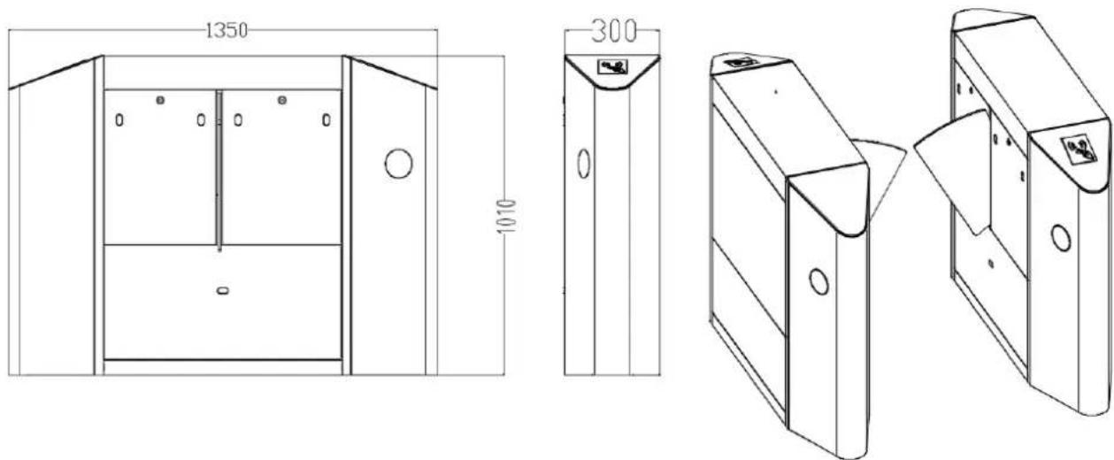
Figure 1-1A FBL4000 series
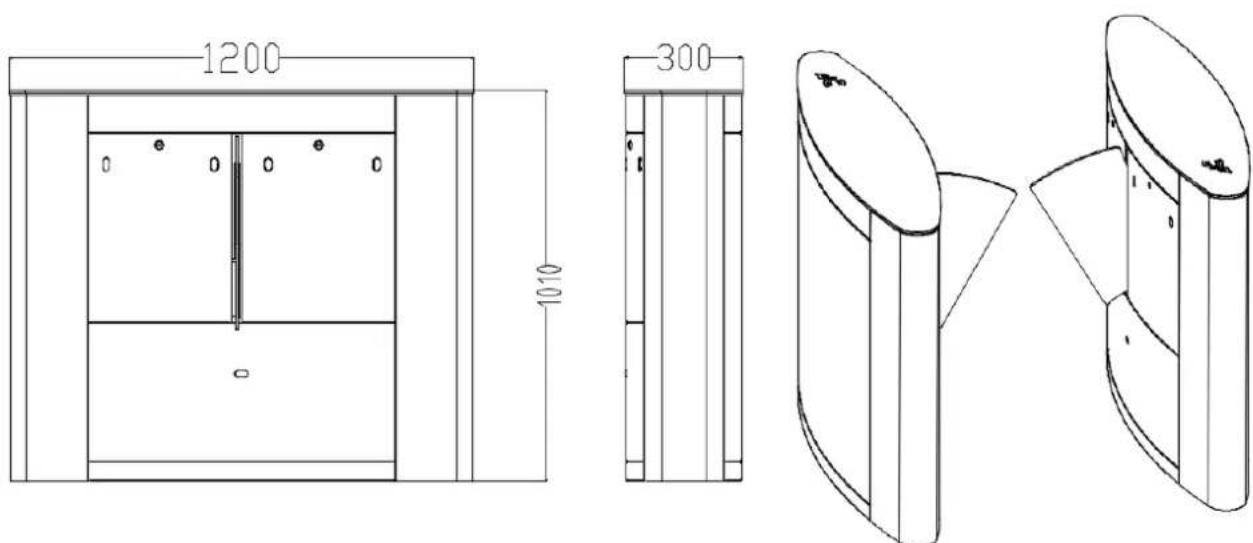
Figure 1-1B FBL5000 series
1.2 Features
1) Passage direction indication function: The LED light indicates whether passage is allowed or not.
2) Anti-stalking function: After each passage, the passage duration is automatically cancelled to prevent stalking.
3) Multiple working modes: The working modes, such as one-way passage, two-way passage, infrared barrier opening, or passage control by sending opening signals to the main board, can be set using the menu on the main board.
4) Automatic reset function: If no person passes through the barrier within the specified period of time after the opening signal is received, the system automatically closes the flap barrier. The specified period of time can be set by using the menu on the main board.
5) Power-off barrier opening function: This function is provided to meet special user requirements.
6) LCD screen: The product provides a LCD screen to directly display the text description of the barrier operation status.
7) Zero-point self-test function: This function is provided to facilitate maintenance and use.
8) Anti-pinch function: This function protects a person against injury caused by closing of the flap barrier or the wing arms at the end of the preset pass-through duration.
9) RS232 serial communication port: This port can be used to control the opening of the barrier.
1.3 Technical Parameters
| Overall dimensions (mm) | FBL 4000 series: L = 1350, W = 300, H = 1010FBL 5000 series: L = 1200, W = 300, H = 1010 | ||
| Length of wing arms | 270mm | Input voltage | AC 100-120V/200-240V, 50-60Hz |
| Input control signal | ON/OFF signal | Output voltage | DC 24V,6.5A |
| Flap barrier ON/OFF duration | 1s | Pass through speed | 25-30 persons/min |
| Ambient temperature range | -28°C to +60°C | Relative humidity | 5% to 80% |
| Number of infrared correlation tubes | 5 pairs | Operating environment | Indoor and outdoor (It is recommended that a canopy be set up.) |
1.4 Product Model and configuration
FBL 4000 series include FBL 4000, FBL 4011 and FBL 4022; FBL 5000 series include FBL 5000, FBL
5011 and FBL 5022, the configuration of each model as shown in figure 1-4.
| Control Panel Model | none | C3-200 and a pair of KR100E | inBIO260 and a pair of FR1200/ID |
| FBL 4000 | √ | ||
| FBL 4011 | √ | ||
| FBL 4022 | √ | ||
| FBL 5000 | √ | ||
| FBL 5011 | √ | ||
| FBL 5022 | √ |
Figure 1-4 Product Model and configuration
Chapter 2 Composition and Basic Operating Principles
2.1 Structure of the Mechanical System
The mechanical system of a flap barrier includes the chassis and the core component. The chassis is a carrier where readers, dust cover, control panel, flap barrier main board, infrared correlation tubes, and door lock are installed. The core component consists of column, electric motor, proximity switch, and wing arms.
2.2 Electronic Control System
The electronic control system mainly consists of readers, control panel, flap barrier main board, infrared correlation tubes, proximity switch, 24V power supply, indicator light and battery (optional). The functions of the main parts are as follows:
1) Reader: The reader reads the user information and sends it to the control panel.
2) Control panel: The control panel judges and processes information from the reader, and then sends it to the flap barrier main board.
3) Flap barrier main board: It is a product control centre that receives signals from the control panel, the infrared correlation tubes and the proximity switch.
4) Infrared correlation tube: It detects the position of a pedestrian and plays the role of safety protection. The infrared correlation tubes at the entrance and exit detect the position of a pedestrian. The anti-pinch infrared correlation tubes play the role of safety protection for the user to avoid injury.
5) Proximity switch: This switch is used to detect the position of the wing arm.
6) 24V power supply: The mains voltage is changed by a transformer to 24V and supplied to the main board.
7) Indicator light: This light helps the pedestrian determine whether it is currently allowed to pass through the barrier. This light also indicates the passage direction. If the indicator light turns green, it means the pedestrian can pass through the channel. If the indicator light turns red, passage is not allowed.
8) Battery (optional): The backup battery serves as the backup power opening the barrier in the event of a power failure.
2.3 Operating Principle of the System
1) After powered on, the flap barrier main board performs self-test to check whether the hardware works normally. If any failure is detected, the system will display a text prompt on the LCD screen. The user can quickly solve the problem based on these prompts.
2) After the reader receives valid user information, the control panel sends barrier opening signals to the flap barrier main board.
3) The flap barrier main board receives, judges and processes the information from the control panel, the infrared correlation tubes and the proximity switch, and then sends commands to the indicator light and the electric motor. The indicator light turns from red to green and the electric motor is activated to open the flap barrier so that the pedestrian can pass through the channel.
Chapter 3 Power-on Test Prior to Installation
Test Procedure
① Connect a temporary test cable to the device and supply the input power of AC 100-120V / 200-240V adaptive to the device (Note that a ground cable must be connected).
② Start the air switch inside the flap barrier and wait 10 seconds till the flap barrier completes the self-test procedure.
③ Check whether the flap barrier and the LED indicators functions properly. If they all function properly, then start the civil installation. If an exception occurs, contact your sales agent.
Chapter 4 Electric and Civil Installation
4.1 Device Installation Conditions and Installation Position
The ground foundation for installation must be a concrete structure to ensure that expansion screws can be fastened securely. If the ground foundation does not meet this condition, consult professional building or decoration personnel and create stable conditions for reliably fastening the flap barrier, for example, drive piles or lay out steel plates.
Determine the device installation position.
Determine the installation position based on the space proportion of the flap barrier by referring to Figure 4-1A, Figure 4-1B and Figure 4-2.
Determine the installation scheme and build one or multiple intelligent management passages.
When a flap barrier is installed against the wall, reserve 100 mm space for opening the upper cover of the flap barrier for maintenance and commissioning. The master machine and slave machine of the FBL 4000 flap barrier not only can form a passage, but also can be installed to form dual passages with one FBL 4200 flap barrier, as shown in Figure 4-1A. The master machine and slave machine of the FBL 5000 flap barrier not only can form a passage, but also can be installed to form dual passages with one FBL 5200 flap barrier, as shown in Figure 4-1B. The unit of data in the figures is mm.
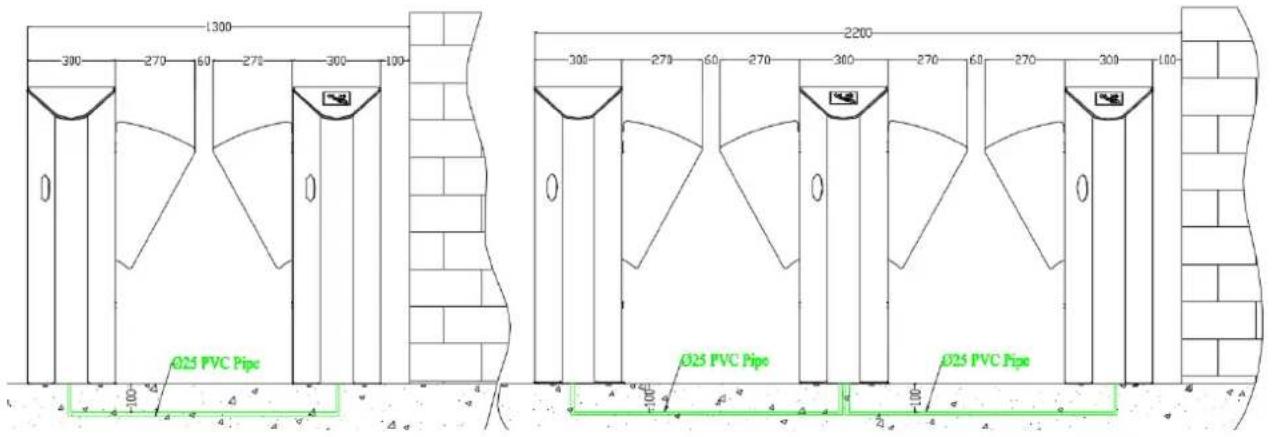
Figure 4-1A Single-Passage and Dual-Passage with FBL 4000
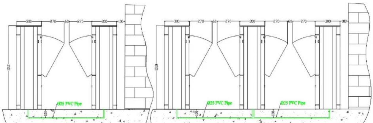
Figure 4-1B Single-Passage and Dual-Passage with FBL 5000
4.2 Cable Installation
For the outlet of concealed cables, see the installation hole positions of the flap barrier in Figure 4-2.
The device uses 6 × 1.5 mm^2 cables with the voltage input range of AC 100-240 V as the power supply cable (including ground cables).
Only professional electricians are allowed to wire the flap barrier and a ground cable must be connected for the flap barrier. A dedicated ground cable binding post is provided on the inner bottom side of the chassis, to ensure that the ground cable at the far end is grounded reliably. Note that the PVC conduits should be buried under the ground for more than 60mm, and the part exposed above the ground should exceed 50mm. In addition, the conduit outlet must be bent to prevent water from entering the conduit.
4.3 Device fixing and Installation
Procedure
① Power ON the master machine and slave machine, adjust the wing arms to ensure that the distance between the wings is 60 mm. Make the wings to be in the OFF state.
② Test whether the infrared rays transmitted by infrared sensors on both sides align with each other.
③ Make marks: Mark the screw hole centers of the base and chassis base edges on the ground.
④ Drill holes: Move away the chassis, get ready a hammer drill and a 14 mm drill bit, and vertically drill a hole with the depth of 80 mm in the screw hole center marks.
Alternatively, drill holes according to installation hole positions. For devices, see Figure 4-2 for installation hole positions. The unit of data in the figures is mm.
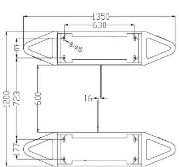
FBL4000
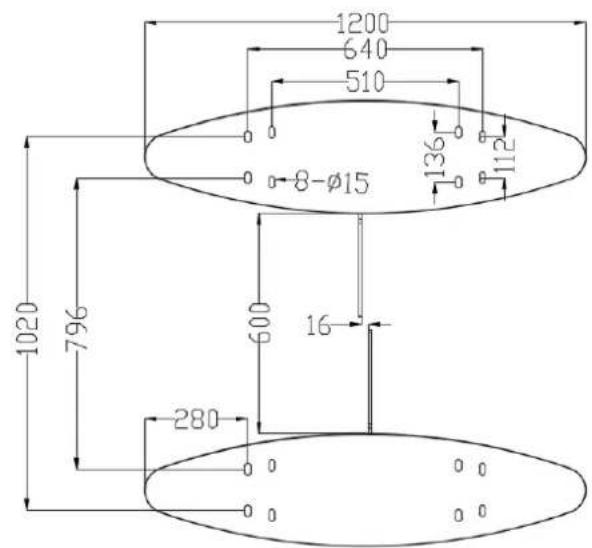
FBL5000
Figure 4-2
⑤ Apply screw glue to the outer surface and threads of the expansion screws, insert expansion screws, and fix the master machine and slave machine in the marked positions. Use a level checker (or spirit level) to check whether the installation ground foundation is in correct level. If not, use a pad for adjustment.
Note: It is recommended that a canopy be set up out of door;
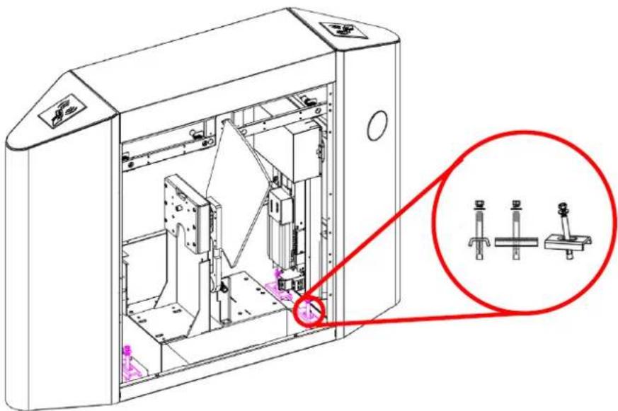
All expansion screws must be completely inserted, as shown in Figure 4-3.
natural_image
Technical line drawing of a mechanical device with internal components and a magnified inset showing three hardware components (no text or symbols)Figure 4-3
4.4 Card Swiping Guard Lines
It is recommended to set guard lines to prompt the users to swipe cards outside the guard lines, as shown in Figure 4-4.
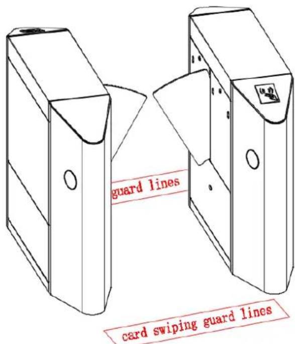
Figure 4-4
Chapter 5 Device Wiring and Commissioning
5.1 Wiring diagram
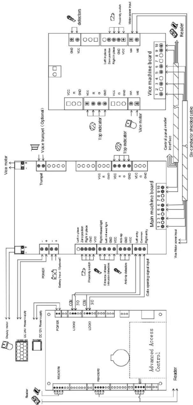
flowchart
graph TD
    subgraph Main machine board
        A["1 2 3 4 5 6 7 8 9 10"] --> B["Gate opening signal input"]
        B --> C["Power"]
        B --> D["Left in place Zero position Right in place GND VCC"]
        B --> E["Right in airied light Left in airied light GND VCC"]
        B --> F["Anti-nip GND VCC"]
        B --> G["Left entry Common Right entry"]
    end

    subgraph Vice machine board
        H["1 2 3 4 5 6 7 8 9 10"] --> I["Main machine board"]
        I --> J["Vice motor power input"]
        I --> K["Control panel reader interface"]
        I --> L["Six-conductor shielded cable"]
    end

    subgraph Voice trumpet (Optional)
        M["Vice motor"] --> N["Top indicator"]
        O["Trumpet"] --> P["Vice trumpet (Optional)"]
        Q["Vice motor"] --> R["Top indicator"]
        S["VOCC"] --> T["Top indicator"]
        U["GND"] --> V["Top indicator"]
        W["VCC"] --> X["Top indicator"]
        Y["R"] --> Z["Top indicator"]
        AA["GND"] --> AB["Top indicator"]
        AC["VCC"] --> AD["Top indicator"]
        AE["G"] --> AF["Top indicator"]
        AG["GND"] --> AH["Top indicator"]
        AI["VCC"] --> AJ["Top indicator"]
        AK["G"] --> AL["Top indicator"]
        AM["GND"] --> AN["Top indicator"]
        AO["MA"] --> AP["Top indicator"]
        AQ["ME"] --> AR["Top indicator"]
    end

    subgraph Gate opening signal input
        AS["Antinip detectors"] --> AT["Entrance infrared intrusion detectors"]
        AU["Proximity switch"] --> AV["Resistance sensor"]
        AW["Access Control"] --> AX["Reader"]
    end

    subgraph Access Control
        AY["Reader4"] --> AZ["DC 24V Power supply"]
        BA["Reader2"] --> BB["DC 12V Power supply"]
    end

    subgraph Voice motor
        BC["-"] --> BD["VOCC"]
        BE["-"] --> BF["VCC"]
    end

    subgraph Voice trumpet
        BG["-"] --> BH["T Trumpet"]
        BI["-"] --> BJ["Vice trumpet (Optional)"]
    end

    subgraph Side indicators
        BK["Vice motor power input"] --> BL["Six-conductor shielded cable"]
        BM["Vice motor power input"] --> BN["Six-conductor shielded cable"]
    end

    subgraph Motor power input
        BO["Vice motor power input"] --> BP["Six-conductor shielded cable"]
        BQ["Vice motor power input"] --> BR["Six-conductor shielded cable"]
    end

    subgraph Side indicators
        BS["Vice motor power input"] --> BT["Six-conductor shielded cable"]
        BU["Vice motor power input"] --> BV["Six-conductor shielded cable"]
    end
5.2 Connection Cables between the Master Chassis and the Slave Chassis
Two 6-core connection cables are deployed between two flap barriers.
5.3 Commissioning of the Standard Machine
1) User registration commissioning on the access controller software
① Connect to access control software, register users and grant permissions to users, verify users, check and commission whether the flap barrier runs properly.
② Trigger access controller to open and close the wings, and check whether the flap barrier runs properly.
2) Commissioning of the integrated access control machine
Check that lines are connected correctly, power on the flap barrier, register users on the integrated access control machine, and check whether the flap barrier runs properly.
6.1 Buttons specification
MENU: to enter menu interface.
UP: to move up a menu item or increase the value.
DOWN: to move down a menu item or reduce the value.
OK: to enter the menu setting item or confirm the current changed value.
CANCEL: to return to the previous menu or to cancel the current operation.
6.2 The operation of the menu
User can press "MENU" button, enter the password and then press "OK" to enter the menu interface. The default password is "UP, UP, DOWN, DOWN, DOWN, DOWN". If any step fails, the user can press the "CANCEL" button to get back.
After entering the menu, user can press "UP" or "DOWN" to choose a menu item and then press "OK" to enter the interface and change function or value.
6.3 The system menu specification
1) Device Type
① Flap barrier
2) Working Mode
① → C, F ←
② F, C
③ F, F
④ → C, C ←
The way of opening barrier could be infrared induction or swiping card. "→ C, F ←" stand for swiping card on the right and infrared induction on the left. "→ F, C ←" stand for infrared induction on the right and swiping card on the left. "→ F, F ←" stand for infrared induction on both sides. "→ C, C ←" stand for swiping card on both sides. The default setting is "→ C, C ←".
3) Passage Control
① → Y, N ←
② N, Y
③ N, N
④ → Y, Y ←
The setting for whether both sides of the machine (entry and exit) are allowed to pass. "→ Y, N ←" stand for being allowed on the right and forbidden on the left. "→ N, Y ←" stand for being forbidden on the right and allowed on the left. "→ N, N ←" stand for being forbidden on both sides. "→ Y, Y ←" stand for being
allowed on both sides. The default setting is "→ Y, Y ←".
4) Direction Setting
① → exit, entry ←
② → entry, exit ←
It is designed to decide which side to serve as entry. "→ exit, entry ←" means that right side is exit and left is entry. "→ entry, exit ←" means that right side is entry and left side is exit. The default setting is "→ exit, entry ←".
5) Open Delay
Press the "UP" and "DOWN" button to adjust the time. Press "OK" button to save.
The default setting for time delay of opening wings after received the opening signal is 0 second.
6) Close Delay
Press the "UP" and "DOWN" button to adjust the time. Press "OK" button to save.
The default setting for time delay of closing wings after a complete passing is 0 second.
7) Open Duration
Press the "UP" and "DOWN" button to adjust the time. Press "OK" button to save.
After the barrier is open, it will automatically close if no one passes. The default setting time is 5 seconds.
8) Memory Function
① → Y, N ←
② N, Y
③ N, N
④ → Y, Y ←
With the memory function, the flap barrier could remember at many swipes of one card at one time and allows many people to pass so they don't have to swipe card each time. "→ Y, N ←" stand for being allowed on the right and forbidden on the left. "→ N, Y ←" stand for being forbidden on the right and allowed on the left. "→ N, N ←" stand for being forbidden on both sides. "→ Y, Y ←" stand for being allowed on both sides. The default setting is "→ N, N ←".
9) Normal Open
① Auto mode
② Manual mode
③ Disable
People can pass freely if the machine in normal open state.
If the "Auto mode" is on, duration time of inputting opening signal exceeds the normal open time setting, the machine will be in normal open state. After the opening signal vanishes, it will exit normal open state.
If the "Manual mode" is on, duration time of inputting opening signal exceeds the normal open time setting, the machine will be in normal open state until it receives the next opening signal.
If the "Disable" is on, the machine will not turn into the normal open state.
The default setting is "Auto mode" mode.
10) NO Time Setting
Press the "UP" and "DOWN" button to adjust the time, press "OK" button to save.
When duration time of inputting opening signal exceeds the setting time, machine will be in normal state. The default setting time is 5 seconds.
11) False Direction In
① Stay open
② Close then open
③ Force to close
The setting for whether barrier will close when people break in passage from the opposite direction. "Stay open" means that barrier will stay open if people break in passage from the opposite direction. "Close then open" means that barrier will close if people break in passage from the opposite direction and then barrier will open again if the people who break in exit passage. "Force to close" means that barrier will close by force if people break in passage from the opposite direction. The default setting is "Stay open".
12) Anti-pinch Detection Time
Press the "UP" and "DOWN" button to adjust the time. Press "OK" button to save.
Flap barrier will stop the process of closing wings if it receives an anti-pinch detection signal during closing. When the lasting time of inputting anti-pinch signal exceeds "Anti-pinch Detection Time", the machine will open again, otherwise it will continue closing. The default setting time is 1 second.
13) AC input when IR is blocked
① Not allowed
② Allowed
The setting for whether it is allowed to swipe card when the infrared is blocked. The default setting is "Not allowed".
14) Battery Mode
① Open
② Disable
This setting is designed for whether the machine will open when the power is off (with battery). The default setting is "Open".
15) Motor Brake
Press the "UP" and "DOWN" button to adjust the level. Press "OK" button to save.
Motor brake is to make the motor stop quickly. But too high level will cause the motor reversal, so it needs fine-tuning according to the actual condition of the machine. The default setting is level 0.
16) Motor Speed
Press the "UP" and "DOWN" button to choose motor and Press "OK" button to enter into the adjusting interface.
Press the "UP" and "DOWN" button on the adjusting interface to adjust the motor speed. Press "OK" button to save.
This setting is used to change the running speed of the motor. And the smaller the value is, the slower speed will be. The default speed for the motor is 8.
Press the "UP" and "DOWN" button to adjust the time. Press "OK" button to save.
It is designed to prevent the motor idling when the control panel is break down for external detection and other reasons causing no signal. The default setting for the maximum motor running time is 3 seconds.
18) Device Number
Press the "UP" and "DOWN" button to adjust the time. Press "OK" button to save.
When many machines are put together, different device number can be used to distinguish, the default number is 1.
19) Device Information
The basic information of the display panel includes type, version and etc.
20) Reset Counter
Reset the counter.
21) System Initialization
After success of the initialization, the panel parameters will be restored to the factory setting and the counter will be reset.
22) IR Sens Delay
Press the "UP" and "DOWN" button to adjust the time. Press "OK" button to save.
It is used to adjust the sensitivity of infrared induction. When an infrared signal is inputted, next infrared signal can be inputted after the time delay. When people pass through the passage, shaking arm will cause the infrared induction making mistake in most case with low time delay. And the high time delay will cause close delaying. So it needs fine-tuning according to the actual condition. The default setting is 0.2 seconds.
23) Close Position
① After central IR zone
② After last IR zone
The barrier can be set to be closed immediately after the person passes through the anti-pinch infrared
(central IR zone) or the last pair of infrared (last IR zone). The default setting is "After central IR zone".
24) Auto testing
The barrier will open repeatedly in accordance with the current setting of the machine parameters. It is mainly used to test the stability and aging of control panel.
For example: if you want to set the working mode.
Step 1: press "MENU", press the button password "UP, UP, DOWN, DOWN, DOWN, DOWN," then press "OK".
Step 2: select "Working Mode" in the menu.
Step 3: press "OK" (display the current working mode).
Step 4: press "OK" again, enter into the interface to choose and modify working mode.
Step 5: press "UP" or "DOWN" to choose corresponding working mode.
Step 6: press "OK" to modify successfully.
Step 7: press "CANCEL" to exit after the setting finished.
Chapter 7 Product Maintenance
1) Non-professional personnel are not allowed to open the chassis and perform tests, maintenance, or repairing on the product.
2) The chassis is made of semi-gloss stainless steel. The chassis surface should be cleaned frequently with a soft silk fabric. Do not use a hard article to wipe the surface to avoid scratches. Water flushing is strictly forbidden so as to avoid water from entering the product, which may result in short circuit of the electronic control system.
3) Each movable part of the product should be checked on a regular basis to prevent loosening of fasteners; otherwise the barrier may fail after long-time operation.
4) Apply lubricating oil to the movable points and the connecting points on a regular basis.
5) Check the circuit connectors and wiring points on a regular basis to ensure reliable connection.
6) Check on a regular basis whether the system's protective earth wire is reliably connected.
7) After repairing or maintaining the product, close the circuit board protection cover and the chassis door.
- Flap Barrier User Manual
- Contents
- Chapter 1 Overview ...... 1
- Chapter 2 Composition and Basic Operating Principles .... 4
- Chapter 3 Power-on Test Prior to Installation....5
- Chapter 4 Electric and Civil Installation .... 6
- Chapter 5 Device Wiring and Commissioning....9
- Chapter 6 The Operation and Specification of the Menu....11
- Chapter 7 Product Maintenance....12
- Chapter 1 Overview
- Product Model and Appearance
- Features
- Technical Parameters
- Product Model and configuration
- Chapter 2 Composition and Basic Operating Principles
- Structure of the Mechanical System
- Electronic Control System
- Operating Principle of the System
- Chapter 3 Power-on Test Prior to Installation
- Test Procedure
- Chapter 4 Electric and Civil Installation
- Device Installation Conditions and Installation Position
- Determine the device installation position.
- Determine the installation scheme and build one or multiple intelligent management passages.
- Cable Installation
- Device fixing and Installation
- Procedure
- Card Swiping Guard Lines
- Chapter 5 Device Wiring and Commissioning
- Wiring diagram
- Connection Cables between the Master Chassis and the Slave Chassis
- Commissioning of the Standard Machine
- 1) User registration commissioning on the access controller software
- 2) Commissioning of the integrated access control machine
- Buttons specification
- The operation of the menu
- The system menu specification
- 1) Device Type
- 2) Working Mode
- 3) Passage Control
- 4) Direction Setting
- 5) Open Delay
- 6) Close Delay
- 7) Open Duration
- 8) Memory Function
- 9) Normal Open
- 10) NO Time Setting
- 11) False Direction In
- 12) Anti-pinch Detection Time
- 13) AC input when IR is blocked
- 14) Battery Mode
- 15) Motor Brake
- 16) Motor Speed
- 18) Device Number
- 19) Device Information
- 20) Reset Counter
- 21) System Initialization
- 22) IR Sens Delay
- 23) Close Position
- 24) Auto testing
- Chapter 7 Product Maintenance
Brand : ZKTeco
Model : FBL4011
Category : Uncategorized