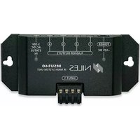
MSU140 - AV Extender Niles - Free user manual and instructions
Find the device manual for free MSU140 Niles in PDF.


| Product Type | IR Main System Unit (AV Extender) |
| Brand | Niles |
| Model | MSU140 |
| Dimensions (W x H x D) | 4-3/4" x 1-1/4" x 2" |
| Weight | 0.5 lb (approx.) |
| Power Supply | 12V DC, 100 mA (included) |
| Power Consumption | 1.2W max |
| Compatibility | Virtually all IR remotes (26-105 kHz carrier) |
| Sensor Inputs | 1 (removable quick connect, category 5 cable) |
| Flasher Outputs | 4 (3.5mm jacks) |
| Status Input | 3-30V AC/DC (3.5mm jack) |
| Cable Type (Sensor) | Category 5, max 500 ft |
| Cable Type (Flasher) | 2-conductor 22 AWG (supplied 10 ft), extendable to 200 ft with 16 AWG |
| Maximum Range (Remote to Sensor) | 15-30 ft depending on remote batteries |
| Mounting | Table-top or wall-mount (integrated mounting wings) |
| LED Indicators | Power (green), IR confirmation (blue) |
| Warranty | 2 years parts and labor |
| Included Accessories | MSU140 unit, screwless connectors, 12V power supply, self-adhesive rubber feet |
| Expandability | Supports IRH610 expansion hub for up to 6 sensor inputs |
| Compatible Sensors/Keypads | WS100, TS100, MS100, MS200, CS100, MVC100IR, IntelliPad |
| Compatible Flashers | MF1, MF2, MF1VF, MF2VF, IRB1 |
| Certification | UL listed power supply |
Frequently Asked Questions - MSU140 Niles
User questions about MSU140 Niles
0 question about this device. Answer the ones you know or ask your own.
Ask a new question about this device
Download the instructions for your AV Extender in PDF format for free! Find your manual MSU140 - Niles and take your electronic device back in hand. On this page are published all the documents necessary for the use of your device. MSU140 by Niles.
USER MANUAL MSU140 Niles
An infrared (IR) extender system enables you to control your IR remote controlled A/V equipment from a remote location. This enables you to place your A/V components out of sight (behind cabinet doors, in the rear of a room, or in a different room) and still conveniently operate your equipment.
Installed at the equipment location, the MSU140 receives the IR commands transmitted from your existing hand-held remotes in that room. The commands are carried via a small category 5 cable to your A/V equipment in another room, and instantly "repeated".
The MSU140 is compatible with all current Niles infrared systems. It may be used along with the Niles TS100, MS100, MS200, WS100, MVC100IR and CS100 IR sensors or the IntelliPad®.
The model MSU140 is an IR Main System Unit. It is one of three elements that make up an infrared extender system:
- IR Main System Unit—Models MSU140, MSU250, MSU480 and MSU440Z.
- IR Sensors/Keypads—Models WS100, TS100, MS100, MS200, CS100, IntelliPad, MVC100IR.
- IR Flashers—Models MF1, MF2, MF1VF, MF2VF and the IRB1.
An IR sensor expansion hub, Model IRH610, is available to provide additional sensor inputs to your system.
Features and Benefits
The MSU140 offers a number of improvements over other IR Extender Main System Units:
- Universal system—compatible with virtually all brands of A/V equipment and remote controls.
- Accommodates one IR sensor or keypad.
- Provides four flasher outputs via convenient 3.5mm jacks.
- System feedback LED confirms operation.
- 3-30V AC/DC status input. Provides system status to connected sensors and keypads.
- Expandable—an IRH610 IR expansion hub can be used to provide additional inputs.
- Printed circuit board design assures high reliability.
- Low profile and small footprint with integrated mounting wings that allow for both horizontal and vertical installation.
- UL listed regulated in-line power supply with universal voltage capability.
- Two year parts and labor warranty.
INFRARED MAIN SYSTEM UNIT
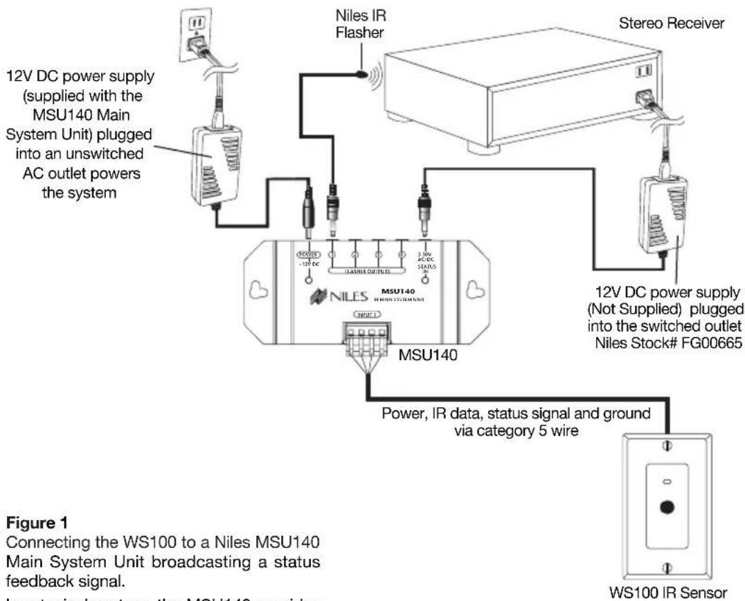
Connecting the WS100 to a Niles MSU140 Main System Unit broadcasting a status feedback signal.
In a typical system, the MSU140 provides for the connection for one remote room sensor (or keypad) and will control multiple audio/video components via its flasher connections.
INFRARED MAIN SYSTEM UNIT
MSU140 Parts Guide

-
12V DC Jack – Provides 12 volt DC power to MSU via a regulated power supply.
-
IR Flasher Outputs - 3.5mm jacks provide output for either single or dual (MF1, MF2, MF1VF, MF2VF) low-level flashers.
-
3-30V AC/DC Status - 3.5mm jack provides system status to sensors/ keypads via a 12 volt power supply attached to a switched outlet on the system receiver or a 12V trigger output.
-
Status/ IR Confirmation LED - This LED performs two functions: (1) it provides a visible indication of system status via a green LED and (2) confirms the reception of IR data via a blinking blue LED.
-
Sensor Input - Removable quick connect sensor plug for connection of IR sensors (WS100, TS100, MS100, MS200, CS100 MVC100IR and the IntelliPad) to the system.
IMPORTANT
Do not place the MSU140 on top of or directly behind a television set. Some television sets produce intense electromagnetic interference which may disable your IR extender system.
Installation Considerations
Placement of the MSU140
Place the MSU140 conveniently close to the equipment it will be controlling. Generally, the unit is placed in a concealed location because its controls and indicators are only used during installation. Placement possibilities include:
1) Table-top (on the shelf behind the equipment) See Figure 2.
2) Wall-mount (affixed to the back of the equipment cabinet or a nearby wall). See Figure 3.

Figure 2: Table-top placement
Affix the enclosed self-adhesive rubber feet to the base of the MSU140.
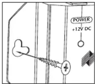
Figure 3: Wall-mount placement Use sheetrock screws
Wiring
From every IR Sensor location you must "home-run" a category 5 cable back to the MSU140. Home run means that an individual cable is connected between each IR Sensor and the MSU140. See Figure 4.

"TECH TIP"

natural_image
Illustration of a black cable with a coiled middle section (no text or symbols)Wire size is expressed by it's AWG (American Wire Gauge) number. The lower the AWG number, the larger the wire, i.e., 20 AWG wire is physically larger than 22 AWG.
IMPORTANT – AVOIDING INTERFERENCE
Avoid locating any of the cables, sensors, keypads or the Main System Unit near any potential sources of Electro-Magnetic Interference (EMI), such as light dimmers, speed controls for ceiling fans, electrical ballasts, television sets, large motors, heaters or air conditioners.
Intellipad Wiring
When you are placing both a Intellipad and a sensor (or two keypads) in one room you may "daisy-chain" using a single cable. A cable is run between the keypad and the sensor and a single cable is run from the sensor back to the MSU140. To prevent data feedback an IN4003 Blocking Diode is inserted on the data (IR) line between the Intellipad and the sensor. The cathode, or blocking side of the diode, faces the Intellipad. See Figure 5. Note that the status wire is connected to Intellipad's status (+) connector.
Figure 5: An IR sensor cable is "daisy-chained" from an Intellipad, to a sensor and back to the MSU140.

Sensor/Keypad Cable
The MSU140 connects to IR sensors and the Intellipad with category 5 cable, with a maximum cable run of 500'.
Flasher Cable
Niles infrared flashers come supplied with a 10 foot 2-conductor 22 gauge cable. Should you need to extend it, use a 16 gauge 2-conductor cable ("zip-cord"). Shielding is not necessary for a flasher. Flasher wires can be extended up to 200 feet.
Installation
Before you begin, make sure that the sensor/keypad cables, the flasher cables and the 12vDC power supply cable will all reach the proposed location of the MSU140. Mark the cables with labels describing where the cable originates (rather than which terminal on the MSU140 it should connect).
For proper installation, follow the steps outlined below in the correct order. If you discover a fault in the course of installation, go on to the Troubleshooting Guide before continuing with the next installation step.
TOOLS REQUIRED
• 1/8" Standard Slotted Screwdriver
- Wire Stripper
STEP DESCRIPTION
- Connect and test the power supply. If it tests OK, unplug the connector from the power socket and proceed.
A) Plug the supplied 12vDC power supply into an unswitched 120V AC outlet, 50-60 HZ.
B) Plug the connector into the socket marked "Power" on the MSU140.
C) If the Power LED does not light, test the unswitched 120 VAC outlet, 50-60 HZ with another appliance. If the outlet tests OK, you have a defective power supply which must be replaced for you to continue.
- Connect the Sensor/ Keypad cable the Sensor input.
A) Strip 1/4" of insulation from the end of each wire. Tightly twist the end of each wire until no frayed ends remain.
B) Use a small flathead screwdriver or your thumbnail to raise the locking tabs, exposing the holes on the removable connectors.
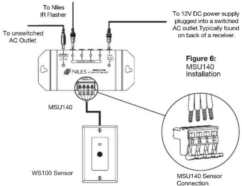
C) Insert each wire into the appropriate hole on the removable connector plug (Figure 6), and snap the locking tab down. To help you, the connector plug is keyed. Insert the smooth side of the connector plug into the smooth side of the socket. Don't force the scalloped side of the connector plug into the smooth side of the socket.
STEP DESCRIPTION
- Test for shorts and interference.
A) Reconnect the power supply. If the Power LED lights and the IR Test LED stays off, unplug the connector from the power socket and proceed to Step 4. The following LED conditions show a fault:
- If Power LED is Off there is a short between +12v and GND
- If IR Test LED is On or flickers blue there is a short between DATA and GND or interference is present.
Before you proceed to Step 4 consult the Troubleshooting Section beginning on page 14.
- Plug the flashers into the flasher outputs. If you need to extend the wire, use a 2-conductor 16 gauge or larger (See "Tech Tip" on page 6).
Route the connecting wire to the IR Main System Unit. Connect the 3.5mm plug into the jack labeled "Flasher Output" on the MSU140. See (Figure 7).
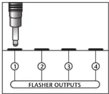
BE SURE TO OBSERVE PROPER POLARITY WHEN EXTENDING THE FLASHER WIRE.
The wire lead marked with a gray stripe is positive (+); the unmarked lead is negative (-).
"TECH TIP"
Make all final connections to the MSU before connecting the power supply. This will avoid potential damage to components.
Figure 7
Testing the IR Extender System
Test your IR Extender system by following these three principal guidelines:
-
All components can be operated. Test all of your remote controls for all of your equipment.
-
Operation is consistent. A good test is to repeatedly step from Pause to Play with your VCR, CD, DVD, or Tape player remote control. Operation should be identical to standing in front of the component with the remote control pointed directly at the sensor window.
-
Maximum Range between the Remote Control and the Niles IR Sensor is similar to the maximum range between the Remote Control and the A/V component's IR sensor. Typically a remote control with two batteries will have a 15 to 20 foot range and a remote with four batteries will have a 20 to 30 foot range.
Power Status — Introduction
To properly wire an Intellipad to the MSU140, refer to Figure 5.
By providing 3-30V AC/DC to the status input jack of your MSU140 you can send a status signal to sensors or an IntelliPad without running any additional wiring. Built into the MSU140 is a Niles status signal generator. When the MSU140 sees 3-30V AC/DC at the status jack it broadcasts a status signal over your existing IR sensor wires. Any sensor or IntelliPad connected to one of your sensor wires will display the power status of your system.
Power Status — Installation Considerations
Proper Power Supply
If status is being supplied from a switched outlet you must connect a Niles 12vDC wall adapter (Niles FG00665) into the switched AC power outlet of the preamp/receiver in your system. Any 12vDC power supply with a minimum of 100mA current capacity can be substituted.
Extending the Cable
If you must extend the cable from the wall adapter to the MSU140's status input jack be sure to maintain correct polarity. The tip of the plug should be positive (+) and the sleeve negative (-). Any 16 gauge 2-conductor cable can be used to extend the power status cable up to 200 feet.
Checking the Power Supply
It is possible to check the status power supply itself and any connections that were made to extend the cable by inserting the status plug into the Power jack on the MSU140. If the Power LED lights the status power supply and connections are ok. If the Power LED does not light check all connections and replace the power supply if necessary. For more details on incorporating the IntelliPad please refer to the IntelliPad's users manual.
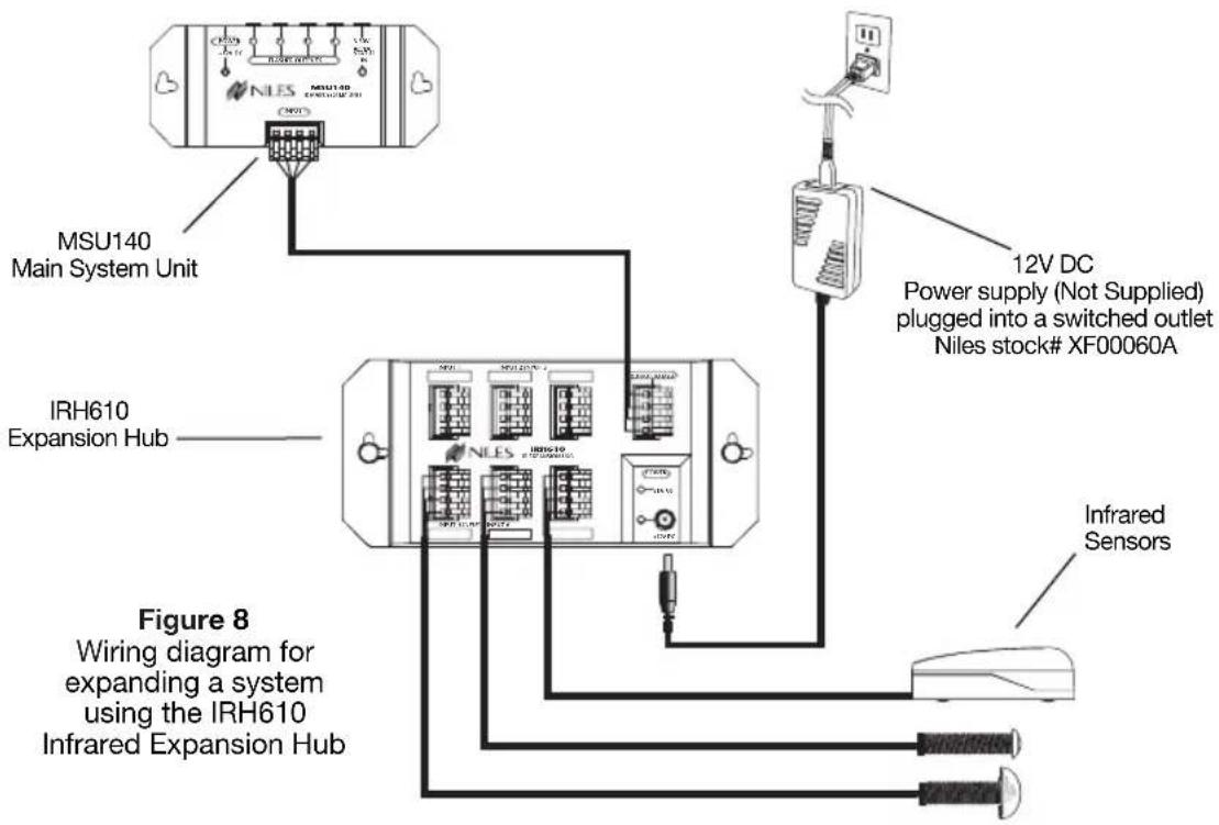
System expansion using an IRH610
The Niles IRH610 can be used to expand an MSU140 beyond a single sensor input. See Figure 8. The IRH610 will allow system expansion to up to six locations. Contact your local authorized Niles dealer or refer to the owner's manual for the IRH610 for details.
INFRARED MAIN SYSTEM UNIT
Troubleshooting Guidelines
There are three basic problems which prevent proper operation. In the order of probability the problems are:
1.- Bad Connections or Wiring
If the connections or wiring are wrong, loose, shorted or open the system will not operate properly. The symptoms could include: Power LED flickers or is off, IR Test LED is continuously flickering or on without any remote control use, intermittent operation or no operation.
Systematically troubleshoot the wiring by:
- Testing your power supply connections.
- Testing your Sensor connections.
- Testing your Flasher connections.
- Testing your cable for shorts and opens.
2.- Optical or Electromagnetic Interference
Direct sunlight, reflections, neon signs and other sources of infrared light or television sets, light dimming controls and other sources of electromagnetic fields can induce noise and interference into your IR extender system. Symptoms can include: flashback LED's continuously flickering or on without any remote control use, poor range, intermittent operation or no operation.
Solution: To eliminate EMI try the following methods:
-
Move the sensor or the sensor cable away from the EMI source or move the source of the EMI away from the sensor or the cable.
-
Connect the Sensor's GND terminal to true earth ground (if this isn't feasible use the main system unit's GND terminal).
If you have an IR sensor in the same room as a flasher, and you have some low-level noise or interference, an optical feedback loop can occur which will interfere with proper operation. Symptoms can include: poor range, intermittent operation or no operation.
Solution: You can eliminate optical feedback by replacing any IRB1 "flooding flasher" with MF1 or MF2 MicroFlashers and covering all flashers with the supplied IR blocking covers.
There are many methods for reducing interference. Which solution is best for you depends on your situation. If you require further assistance contact Niles Technical Support at 1-800-289-4434.
INFRARED MAIN SYSTEM UNIT
Specifications
IR System
Compatible with virtually all brands of remotes using carrier frequencies between 26 and 105kHz.
Wiring Requirements
Individual home-runs of category 5 cable from each sensor/keypad.
Unit Dimensions
4-3/4" wide x 1-1/4" high x 2" deep
Power Requirements
12VDC power supply (included).
Contents
MSU140 1
Screwless Connectors 1
In-line Power Supply 1
Self-Adhesive
Rubber Feet 4
Addendum: Using the MSU140 with the IntelliControl® automation system

Using the MSU140 with the IntelliControl Home Theater automation system
When connecting an MSU flasher output to an IntelliControl "Home Theater" port, a 150-Ohm resistor must be placed between the data and the ground line of the IntelliControl IR sensor input (see figure above). No resistor is needed if the MSU is being connected to the "2nd Zone" port of the IntelliControl.

NILES.
Niles Audio Corporation
www.nilesaudio.com
12331 S.W. 130 Street
Miami, Florida, 33186
Tel: (305) 238-4373
Fax: (305) 238-0185
©2004 Niles Audio Corporation. All rights reserved. Niles, the Niles logo, IntelliPad and Blending High Fidelity and Architecture are registered trademarks of Niles Audio Corporation. MicroFlasher is a trademark of Niles Audio Corporation. Because we strive to improve our products. All other trademarks are the property of their respective owners. Niles reserves the right to change product specifications without notice. The technical and other information contained herein is not intended to set forth all technical and other specifications of Niles products. Additional information can be obtained on-line at www.nilesaudio.com or by calling Niles at 1-800-289-4434. 01/04 Printed in China DS00329ACN
- Features and Benefits
- INFRARED MAIN SYSTEM UNIT
- MSU140 Parts Guide
- IMPORTANT
- Installation Considerations
- Placement of the MSU140
- Wiring
- IMPORTANT – AVOIDING INTERFERENCE
- Intellipad Wiring
- Sensor/Keypad Cable
- Flasher Cable
- Installation
- TOOLS REQUIRED
- STEP DESCRIPTION
- "TECH TIP"
- Testing the IR Extender System
- Power Status — Introduction
- Power Status — Installation Considerations
- Proper Power Supply
- Extending the Cable
- Checking the Power Supply
- System expansion using an IRH610
- Troubleshooting Guidelines
- 1.- Bad Connections or Wiring
- 2.- Optical or Electromagnetic Interference
- Specifications
- Contents
- Addendum: Using the MSU140 with the IntelliControl® automation system
- Using the MSU140 with the IntelliControl Home Theater automation system
Brand : Niles
Model : MSU140
Category : AV Extender