99-8214 - Car radio Metra - Free user manual and instructions
Find the device manual for free 99-8214 Metra in PDF.


| Product Type | Car stereo installation dash kit |
| Compatible Vehicles | Toyota Tacoma 2005-2011 |
| Radio Provisions | DIN, ISO DIN, Double DIN |
| Color Options | Black (99-8214TB), Gray (99-8214TG) |
| Texture | Factory golf ball texture, painted to match dash |
| Kit Components | Radio housing, brackets, trim panels, ISO brackets, screws |
| Wiring Harness (sold separately) | 70-1761 (Toyota 1987-up), TYTO-01 (2003-up) |
| Antenna Adapter | Not required |
| Tools Required | Panel removal tool, Phillips screwdriver, socket wrench |
| Installation Difficulty | Moderate |
| Dimensions (approx.) | Double DIN (approx. 180 x 100 mm), pocket available for single DIN |
| Weight | Approx. 0.5 kg (1.1 lbs) |
| Material | Plastic, painted |
| Maintenance | Wipe clean with damp cloth; avoid harsh chemicals |
| Safety Precautions | Disconnect battery before installation; do not overtighten screws |
| Repairability | Non-serviceable plastic parts; replace entire kit if damaged |
| Warranty | Check manufacturer details |
| Brand | Metra |
| Part Number | 99-8214 |
Frequently Asked Questions - 99-8214 Metra
User questions about 99-8214 Metra
0 question about this device. Answer the ones you know or ask your own.
Ask a new question about this device
Download the instructions for your Car radio in PDF format for free! Find your manual 99-8214 - Metra and take your electronic device back in hand. On this page are published all the documents necessary for the use of your device. 99-8214 by Metra.
USER MANUAL 99-8214 Metra
INSTALLATION INSTRUCTIONS FOR PART 99-8214
APPLICATIONS
See application list inside
Toyota Tacoma 2005-2011 99-8214
KIT FEATURES
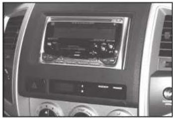
• DIN radio provision with pocket
• ISO DIN radio provision with pocket
• Double DIN radio provision
- Painted and textured to match factory dash
• Available in: Black 99-8214TB or Gray 99-8214TG
- Both kits are factory "golf ball" textured
natural_image
Close-up of a car dashboard with a digital display showing engine, air, and control buttons (no visible text or symbols)KIT COMPONENTS
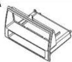
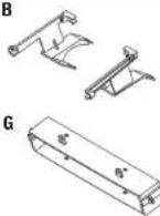
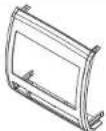
• A) Radio housing • B) Radio housing brackets • C) Radio housing trim panel • D) ISO Brackets
• E) ISO Trim plate • F) Double DIN trim plate • G) Clock/Hazard switch bracket
• H) (4) #6 x 3/8" Phillips pan head screws • I) (4) #8 X 3/8" Phillips truss head screws




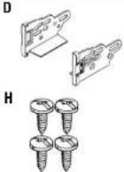

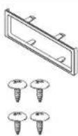

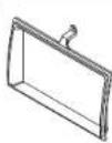
WIRING & ANTENNA CONNECTIONS (sold separately)
Wiring Harness:
• 70-1761 Toyota harness 1987-up
• TYTO-01 Toyota amp interface harness 2003-up
Antenna Adapter:
- Not Required
TOOLS REQUIRED
- Panel removal tool • Phillips screwdriver
- Socket wrench
CAUTION: Metra recommends disconnecting the negative battery terminal before beginning any installation. All accessories, switches, and especially air bag indicator lights must be plugged in before reconnecting the battery or cycling the ignition.
NOTE: Refer to the instructions included with the aftermarket radio.
Table of Contents
Dash Disassembly
- Toyota Tacoma 2005-2011 2-3
Kit Preparation
- Toyota Tacoma 2005-2011 ....3
Kit Assembly
- DIN radio provision with pocket ....4
- ISO DIN radio provision with pocket ....5
- Double DIN radio provision ....6
Toyota Tacoma 2005-2011
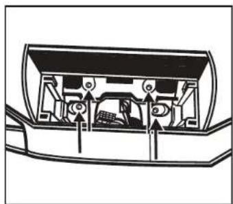
- Unclip and remove A/C control panel. (Figure A)
- Remove (4) 10 mm bolts securing radio. (Figure B)
- Unclip and remove entire panel including hazard switch and clock. (Figure C)
Continued on next page
natural_image
Cross-sectional diagram of a vehicle showing internal components and directional arrows (no text or labels)(Figure B)
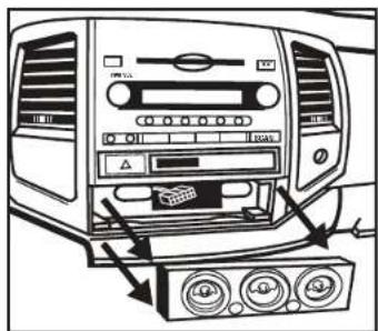
(Figure A)
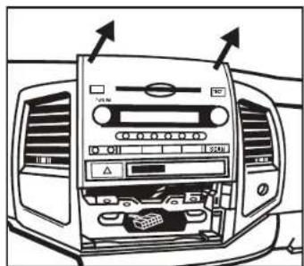
(Figure C)
Toyota Tacoma 2005-2011
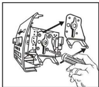
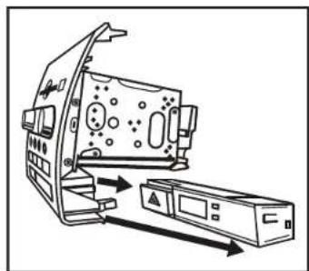
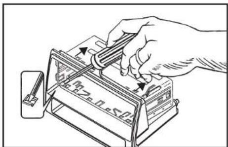
- Remove the left and right radio brackets from the radio chassis. (Figure D)
- Unclip and remove the clock/hazard switch assembly from the factory radio housing trim panel. (Figure E)
Continue to kit preparation
natural_image
Technical illustration of a hand using a tool to adjust or install a mechanical component (no text or symbols visible)(Figure D)
Kit Preparation
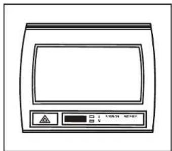
- Attach the clock/hazard switch bracket to the radio housing using the (4) #6 x 3/8" Phillips pan head screws.
WARNING: DO NOT OVERTIGHTEN SCREWS. - Clip the clock/hazard switch assembly into the 99-8214 radio housing trim panel. (Figure A, B)
Continue to kit assembly
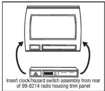
(Figure A)
natural_image
Diagram of a device with an open lid and internal components, showing directional arrows indicating movement (no text or symbols present)(Figure E)
(Figure B)

Kit Assembly 99-8214
DIN radio provision with pocket
- Locate the factory wiring harness in the dash. Metra recommends using the proper mating adapter from Metra or AXXESS. Re-connect the negative battery terminal and test the radio for proper operation.
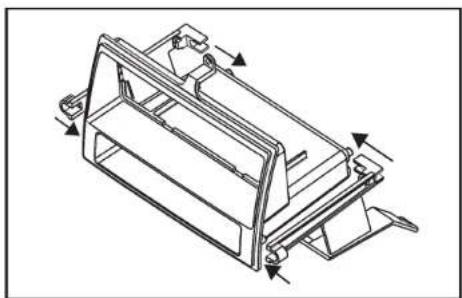
- Attach the corresponding radio housing bracket to the radio housing using the included (4) #8 x 3/8" Phillips truss head screws. (Figure A)
- Slide the DIN cage into the radio housing and secure by bending the metal locking tabs down. (Figure B)
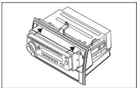
- Slide the aftermarket radio into the cage and secure. (Figure C)
- Secure the radio housing into the dash using the factory hardware.
- Reassemble dash in reverse order of disassembly.
natural_image
Technical line drawing of a mechanical housing or enclosure component (no text or symbols)(Figure A)
natural_image
Technical line drawing of a mechanical device with ports and control panel (no text or symbols)(Figure C)
(Figure B)

99-8214
ISO DIN radio provision with pocket
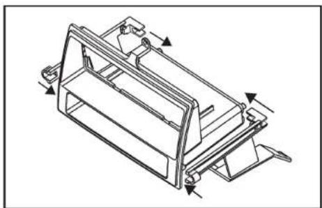
- Locate the factory wiring harness in the dash. Metra recommends using the proper mating adapter from Metra or AXXESS. Re-connect the negative battery terminal and test the radio for proper operation.
- Attach the corresponding radio housing bracket to the radio housing using the included (4) #8 x 3/8" Phillips truss head screws. (Figure A)
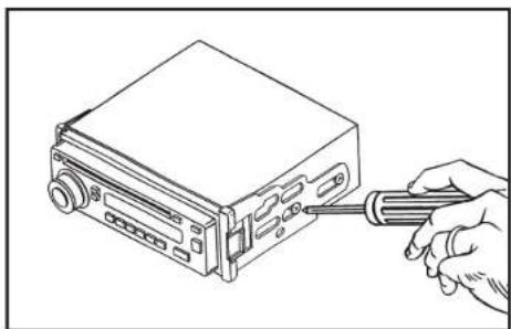
- Mount the ISO brackets to the radio with the screws supplied with the radio. (Figure B)
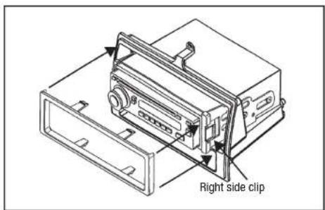
- Slide the radio into the radio opening until the side clips engage. (Figure C)
- Snap the ISO trim plate into the radio housing. (Figure C)
- Secure the radio housing into the dash using the factory hardware.
- Reassemble dash in reverse order of disassembly.
natural_image
Technical line drawing of a mechanical housing or enclosure component with mounting brackets and directional arrows indicating movement (no text or symbols)(Figure A)
(Figure C)
natural_image
Line drawing of a hand inserting a screwdriver into a device casing (no text or symbols)(Figure B)

Kit Assembly 99-8214
Double DIN radio provision
- Locate the factory wiring harness in the dash. Metra recommends using the proper mating adapter from Metra or AXXESS. Re-connect the negative battery terminal and test the radio for proper operation.
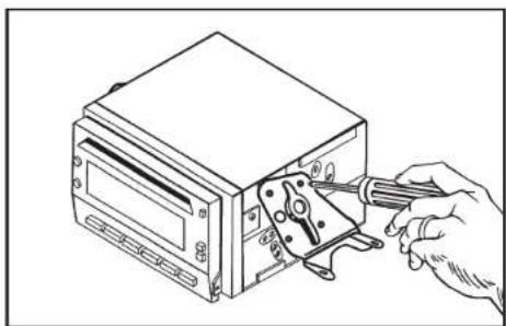
- Slide the aftermarket radio unit into the factory brackets and secure the unit to the brackets using the screws supplied with the head unit. (Figure A)
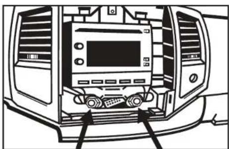
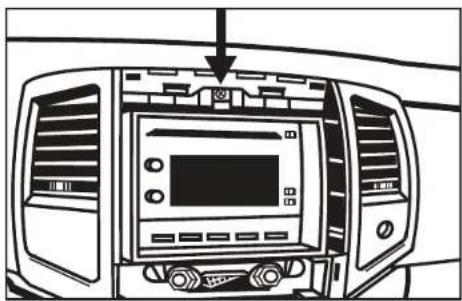
- Secure the aftermarket radio unit and factory bracket assembly into the sub dash. (Figure B)
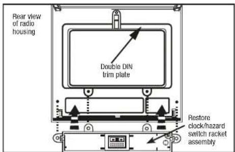
- Place the Double DIN trim plate into the back of the radio housing, then attach the clock/hazard switch bracket assembly using the (4) #6 x 3/8" Phillips pan head screws. (Figure C)
WARNING: DO NOT OVERTIGHTEN SCREWS.
- Clip the clock/hazard switch assembly into the 99-8214 radio housing trim panel. (Figure D)
- Reassemble dash in reverse order of disassembly.
natural_image
Line drawing of a hand using a tool to adjust or install electronic components on a device (no text or symbols visible)(Figure A)
natural_image
Line drawing of a car front panel with buttons and a monitor (no text or symbols)(Figure B)
natural_image
Line drawing of a car dashboard with air vent and control panel (no text or symbols)(Figure C)
(Figure D)

INSTALLATION INSTRUCTIONS FOR PART 99-8214


KNOWLEDGE IS POWER
Enhance your installation and fabrication skills by enrolling in the most recognized and respected
mobile electronics school in our industry.
Log onto www.installerinstitute.com or ca
600-354-6782 for more information and take steps

Metra recommends MECP
certified technicians
METRA. The World's best kits. ^TM
metraonline.com1-800-221-0932 METRA ELECTRONICS CORPORATION
- Toyota Tacoma 2005-2011 99-8214
- KIT FEATURES
- KIT COMPONENTS
- WIRING & ANTENNA CONNECTIONS (sold separately)
- TOOLS REQUIRED
- Table of Contents
- Dash Disassembly
- Kit Preparation
- Kit Assembly
- Toyota Tacoma 2005-2011
- DIN radio provision with pocket
- ISO DIN radio provision with pocket
- Double DIN radio provision
Brand : Metra
Model : 99-8214
Category : Car radio