DXP V0808 - Switch RGBlink - Free user manual and instructions
Find the device manual for free DXP V0808 RGBlink in PDF.


| Product Type | Matrix Switcher |
| Model | DXP V0808 |
| Brand | RGBlink |
| Inputs | 8 VGA (DB15) |
| Outputs | 8 VGA (DB15) |
| Switching Capability | Any input to any output |
| Independent Output Switching | Yes |
| Control Methods | Front panel, IR remote, RS-232 |
| RS-232 Loop Out | Yes, for multiple device control |
| EDID Management | Supported |
| Modular Input/Output | Yes |
| Video Bandwidth | 250 MHz (-3dB) |
| VGA Bandwidth | 500 MHz (-3dB) |
| Supported Resolutions | Up to 2048x1536@60Hz |
| Preset Scenarios | 24 user-defined, plus 1 default (1:1) |
| Display | Monochrome LCD |
| Power Supply | IEC-3 port, 100-240V AC |
| Dimensions (approx.) | 1U rack mount, ~19" width |
| Weight (approx.) | 2.5 kg |
| Warranty | 3 years parts and labor |
Frequently Asked Questions - DXP V0808 RGBlink
User questions about DXP V0808 RGBlink
0 question about this device. Answer the ones you know or ask your own.
Ask a new question about this device
Download the instructions for your Switch in PDF format for free! Find your manual DXP V0808 - RGBlink and take your electronic device back in hand. On this page are published all the documents necessary for the use of your device. DXP V0808 by RGBlink.
USER MANUAL DXP V0808 RGBlink
DXP V0808 Quick Start
natural_image
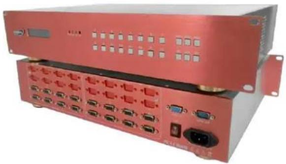
Red industrial electronic device rear panel with ports and connectors (no visible text or symbols)■ Support any in any out
■ Support independent output switching
■ Support infrared remote control
■ Input and output can be modularized
■ RS 232 loop out for mulple control
■ Support EDID management
CONTENT
Product Introduction....2
Packing Configuration .... 3
Hardware Orientation ....4
Front Panel....4
Back Panel 5
Operating Instruction......6
Content....6
How to Switch between Input and Output Channel....7
How to Switch One Input to all Outputs....7
How to Close One Output Channel ....7
How to Close all Output Channels....8
How to Set One-to-one Correspondence for Input and Output Channel ....8
How to Save Pre-set Input and Output Channel ....8
How to Call Pre-set Input and Output Channel Saving Mode....9
How to Factory Reset 9
How to Read Equipment Related Information....9
How to Set LOGO Display when Power on....10
Contact Information....11
Product Introduction
Matrix switching system is the whole cross high performance device, used for signal switching. Mainly used in television broadcasting system signal switching and exchange, multimedia meeting room, large screen projection display engineering, government conference room, hospital medical discussion conference room, television signal switching, interactive multimedia classrooms, and military command video conference room.
RGBlink strong technical strength determines the high quality of AVDXP series matrix switchers. We choose the chips with best performance, elaborate design for every way of switchers, to ensure the high quality of switchers. After rigorous testing, VGA switching signal bandwidth is 500 MHz (-3db), support resolution of 1024x768@60Hz to 2048x1536@60Hz, fully meet various strict
requirements and high quality occasions.
Video for 250MHz (-3db), can not only support various of video signals, but also meet the future high-definition television (HDTV) bandwidth requirements.
RGBlink matrix switchers provide the good man-machine interface for users.
Switchers in this series are equipped with monochromatic LCD, RS 232 communication interface, with outage protect function, can read and store up to 24 user scenarios. The system is equipped with multiple sets of serial instructions, can in conjunction with computer, remote control system or all kinds of distal control equipment.
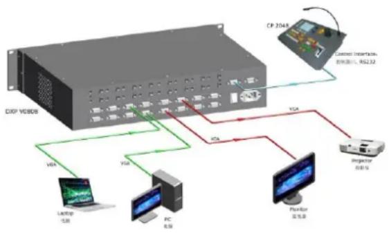
System Connection
RGBlink offers solutions to demanding technical problems.
Any application questions, or required further information,
please contact with our customer Support Engineers.
flowchart
graph TD
    A["DXP V8008"] -->|V84| B["Laptop 5.8"]
    A -->|V84| C["PC 4.5"]
    A -->|V84| D["Pointer 5.5"]
    A -->|V84| E["Injector 6.9"]
    F["CP 2048"] -->|Control Interface, 防接接口, V82.32| A
    F -->|Control Interface, 防接接口, V82.32| G["Injector 6.9"]
DXP V0808 System Connection Diagram
Packing Configuration
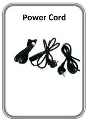
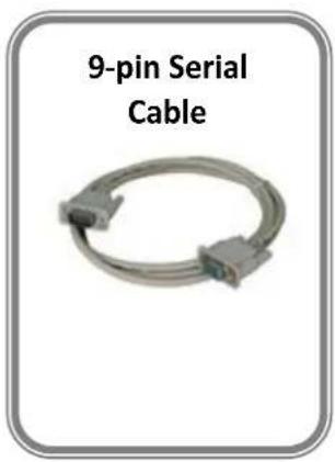
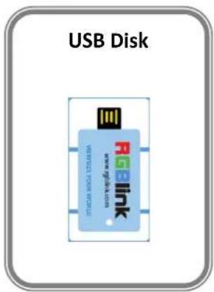
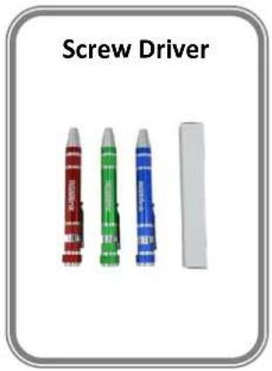
Note: Chinese Standard, American Standard or European Standard power cord is option. The color of the screw driver is randomly when packing.
Front Panel

| Button Instruction | |||
| 0~8 | Selection button for input and output channel, and number choice of save or call saving modes. [0] button can also be used to shut down the channel output. | Rec | Load button |
| 20+ | UP arrow button and decimal button | Save | Save button |
| 30+ | Down arrow button | Esc | Exit button |
| ALL | Distributor selection button | LED indicator | Power indicator |
| F1. F2 | Fast call user save mode | Mode indicator | |
| Menu | Menu button | Com indicator | |
| Mode | Audio and video switching button | IR receiver | Receive the infrared signal |
| Enter | Confirm button | LCD Panel | Show operation menu items |
Back Panel
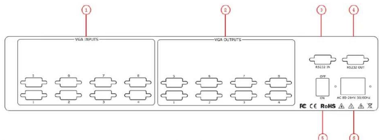
| Input Interface | |
| 1 | VGA Input DB15 port |
| Output Interface | |
| 2 | VGA Output DB15 port |
| Other Interface | |
| 3 | RS 232 IN serial communication interface |
| 4 | RS 232 OUT serial communication interface |
| 5 | Switch |
| 6 | Power IEC-3 port |
Operating Instruction
Content
How to Switch between Input and Output Channel
▶ How to Switch One Input to all Outputs
▶ How to Close One Output Channel
▶ How to Close all Output Channels
How to Set One-to-one Correspondence for Input and Output Channel
How to Save Pre-set Input and Output Channel
How to Call Pre-set Input and Output Channel Saving Mode
▶ How to Factory Reset
How to Read Equipment Related Information
How to Set LOGO Display when Power on
How to Switch between Input and Output Channel
DXP V0808 can rapidly switch any way signals by the front panel buttons, specific operations are as follows:
- Push the number button to select the input channel, for example, push the button [3].
- Push the number button again to select the output channel, for example, push the button [5].
- After selection, push the button [Enter] to confirm.
Note: Input channel: The signal that will be switched to output channel.
Output channel: The signal that connected to display device.
The number [1]\~[8] means channel 1\~8.
How to Switch One Input to all Outputs
- Push the number button, for example, push the button [2].
- Then push the button [ALL], and input 2 will be switched to all outputs.
User can also operate by the following ways: - Push the button [ALL].
- Then choose the input channel, for example, push the button [2].
- Push the button [Enter] to confirm.
How to Close One Output Channel
- Push the button [0] on the front panel.
- Choose output channel, for example, push the button [8].
- Push the button [Enter] to confirm.
How to Close all Output Channels
- Push the button [0] on the front panel.
-
Then push the button [ALL] on the front panel.
User can also operate by the following ways: -
Push the button 【ALL】on the front panel.
- Push the button 【0】 on the front panel.
- Push the button [Enter] to confirm.
How to Set One-to-one Correspondence for Input and Output Channel
- Push the button [Rec] on the front panel.
- Push the button [0] on the front panel.
- Push the button [Enter] to confirm.
How to Save Pre-set Input and Output Channel
- Push the button [Save] on the front panel.
- User can choose 24 kinds of mode from button [1]\~[24], for example, push the button [2].
- Push the button [Enter] to confirm.
How to Call Pre-set Input and Output Channel Saving Mode
- Push the button [Rec] on the front panel.
- User can choose 25 kinds of mode from button [0]\~[24], for example, push the button [7].
- Push the button [Enter] to confirm.
Note: [0] is default for one-to-one correspondence for input and output way. That is input [1] is corresponding to output [1], input [2] is corresponding to output [2]...
How to Factory Reset
- Push the button [Menu] on the front panel.
- Push the button [30+] DOWN arrow button, or button [20+] UP arrow button, make RESET option for selected state.
- Push the button [Enter] to confirm and enter the initialization interface.
- Push any button according to the LCD hint and complete factory reset.
How to Read Equipment Related Information
- Push the button [Menu] on the front panel.
- System default STATUS option, if it is not selected, push the [30+] DOWN arrow button or [20+] UP arrow button and choose
. - Push the button [Enter] to confirm, read the information by the [30+] DOWN arrow button or [20+] UP arrow button.
How to Set LOGO Display when Power on
- Push the button [MENU] on the front panel.
- Push the [30+] DOWN arrow button or [20+] UP arrow button and select
. - Push the button [Enter] to confirm, and enter LOGO switch setting, LOGO ON or OFF at boot can be set.
Warranty:
All video products are designed and tested to the highest quality standard and backed by full 3 years parts and labor warranty. Warranties are effective upon delivery date to customer and are non-transferable. RGBlink warranties are only valid to the original purchase/owner. Warranty related repairs include parts and labor, but do not include faults resulting from user negligence, special modification, lighting strikes, abuse (drop/crush), and/or other unusual damages.
The customer shall pay shipping charges when unit is returned for repair.
Headquarter: S603\~604 Weiye Building Torch Hi-Tech Industrial Development Zone Xiamen, Fujian Province, P.R.C
• Tel: +86-592-5771197
• Fax: +86-592-5771202
• Customer Hotline: 4008-592-315
- Web:
\~ http://www.rgblink.com
\~ http://www.rgblink.cn
• E-mail: support@rgblink.com
- DXP V0808 Quick Start
- CONTENT
- Product Introduction....2
- Packing Configuration .... 3
- Hardware Orientation ....4
- Operating Instruction......6
- Contact Information....11
- Product Introduction
- System Connection
- Packing Configuration
- Front Panel
- Operating Instruction
- How to Switch between Input and Output Channel
- How to Switch One Input to all Outputs
- How to Close One Output Channel
- How to Close all Output Channels
- How to Set One-to-one Correspondence for Input and Output Channel
- How to Save Pre-set Input and Output Channel
- How to Call Pre-set Input and Output Channel Saving Mode
- How to Factory Reset
- How to Read Equipment Related Information
- How to Set LOGO Display when Power on
- Warranty:
Brand : RGBlink
Model : DXP V0808
Category : Switch