
MX-HDBT8X818G - Network switch KanexPro - Free user manual and instructions
Find the device manual for free MX-HDBT8X818G KanexPro in PDF.


| Product Type | 8x8 HDMI over HDBaseT Matrix Switch / Network Switch |
| HDMI Inputs | 8 x HDMI (Type A female) |
| HDMI Outputs | 8 x HDBaseT (RJ45) with balanced audio output |
| Maximum Resolution | 4K@60Hz 4:4:4 (up to 18Gbps) |
| HDBaseT Distance | Up to 100m (328 ft) over Cat6a/7 cable |
| Ethernet Port | 1 x RJ45 for control (TCP/IP, RS-232) |
| Control Interface | Front panel buttons, IR remote, RS-232, Ethernet |
| EDID Management | Built-in EDID learning and emulation |
| Audio Support | LPCM 2.0/5.1/7.1, Dolby Digital, DTS-HD, Dolby TrueHD |
| Power Supply | 100-240V AC, 50/60Hz, max 50W (internal) |
| Dimensions (W x D x H) | 17.0 x 10.5 x 1.75 inches (rack-mount 1U) |
| Weight | 10.5 lbs (approx.) |
| Operating Temperature | 32°F to 104°F (0°C to 40°C) |
| Storage Temperature | -4°F to 140°F (-20°C to 60°C) |
| Relative Humidity | 10% to 90% non-condensing |
| Maintenance | Wipe with a soft, dry cloth. Do not use liquids or solvents. |
| Safety | Use only with grounded outlets. Do not open the unit. Risk of electric shock. |
| Spare Parts / Reparability | No user-serviceable parts inside. Contact authorized service center for repairs. |
| Certifications | CE, FCC, RoHS |
| General Information | Supports HDMI 2.0b, HDCP 2.2, and HDR10/Dolby Vision. Rack-mountable. |
Frequently Asked Questions - MX-HDBT8X818G KanexPro
User questions about MX-HDBT8X818G KanexPro
0 question about this device. Answer the ones you know or ask your own.
Ask a new question about this device
Download the instructions for your Network switch in PDF format for free! Find your manual MX-HDBT8X818G - KanexPro and take your electronic device back in hand. On this page are published all the documents necessary for the use of your device. MX-HDBT8X818G by KanexPro.
USER MANUAL MX-HDBT8X818G KanexPro
8 by 8 HDMI and HDBaseT Matrix Switcher with Audio Matrixing
All Rights Reserved
MPN# MX-HDBT8X818G
Thank you for purchasing this product
For optimum performance and safety, please read these instructions carefully before connecting, operating or adjusting this product. Please keep this manual for future reference.
Surge protection device recommended
This product contains sensitive electrical components that may be damaged by electrical spikes, surges, electric shock, lighting strikes, etc. Use of surge protection systems is highly recommended in order to protect and extend the life of your equipment.
Table of Contents
- Introduction......3
- Features .... 3
- Package Contents ....4
- Specifications....5
- Operation Controls and Functions....6
5.1 Front Panel....6
5.2 Rear Panel....8 - IR Remote 10
- IR Control System 12
- IR Cable Pin Assignment....15
- HDBaseT Receiver....15
- EDID Management ...... 17
- Audio Matrix.... 19
- Web GUI User Guide.... 21
- ASCII control command.... 31
- Application Example....37
- FAQ....38
1. Introduction
The 8 by 8 HDMI and HDBaseT Matrix Switcher supports transmission of video (resolution up to 4K2K@60Hz YUV 4:4:4, 18Gbps, HDCP 2.2) and audio (multi-channel digital / analog stereo) while providing flexible control via front panel button (with OLED screen), IR remote, RS-232 or Web GUI. You can switch any of 8 sources to 2 independent HDMI 2.0 outputs and 6 HDBaseT outputs. These HDBaseT ports extend distance up to 330 feet / 100 meters and resolution up to 1080p@60Hz or distance up to 295 feet / 90 meters and resolution up to 4K2K@60Hz YUV 4:4:4 via single CAT6/6a/7 cable. All HDMI outputs support internal audio embed, you can choose the internal embed audio by Web GUI.
The Matrix Switcher built-in an independent audio matrix and the audio matrix can be choose audio input signal from 6 external audio sources, 8 HDMI inputs audio or 8 ARC audio inputs, and audio volume / mute / delay function can be adjusted by Web GUI. Moreover, the product supports two-way IR function (except 2 local HDMI outputs), and the IR control follows HDMI video channel.
The product provides an intuitive set of front panels with OLED screen and supports front panel button, IR remote, RS-232 or Web GUI control ways.
2. Features
☆ HDMI 2.0b, HDCP 2.2 and HDCP 1.4 compliant
☆ Support 8 HDMI sources to 2 independent HDMI outputs and 6 HDBaseT
outputs
☆ Video resolution up to 4K@60Hz (YUV 4:4:4) for all HDMI ports
☆ All HDMI outputs support audio embed and de-embed
☆ All HDBaseT ports support 4k@60Hz (YUV 4:4:4) and distance up to 295 feet / 90 meters or 1080p@60Hz and distance up to 330 feet / 100 meters via CAT 6/6a/7 cable
☆ All HDBaseT support feature: High-Definition video and audio, 24V PoC
(Transmitter is powered and Receiver don’t need to power supply) and control (Bi-directional IR & RS-232 pass-through)
☆ HDMI Pass-through audio up to 7.1 channels of high definition audio (LPCM, Dolby TrueD and DTS-HD Master Audio)
Built-in independent audio matrix with volume, mute and audio delay adjustment (PCM 2.0 only)
☆ HDR, ARC, CEC and smart EDID management are supported
☆ Control via front panel button, IR remote, RS-232 and Web GUI
☆ 2U rack mounted design with aluminum housing on the front
3. Package Contents
① 1x 8 by 8 HDMI and HDBaseT Matrix Switcher
② 6x HDBaseT Receivers
③ 9x Wideband IR Blaster cables
④ 10x Wideband IR Receiver cables
⑤ 1x Matrix IR Remote
⑥ 1x 100\~240V AC 50/60Hz Power cable
⑦ 1x RS-232 serial cable (1.5m, male to female head)
⑧ 16x 3-pin Phoenix Connectors
⑨ 12x Mounting Ears
⑩ 1x User Manual
4. Specifications
| Technical | |
| HDMI Compliance | HDMI 2.0b |
| HDCP Compliance | HDCP 2.2 and HDCP 1.4 |
| Video Bandwidth | 18Gbps |
| Video Resolution | Up to 4K2K@50/60Hz (YUV 4:4:4),4K2K@24/30Hz, 1080p@120Hz and 1080p3D@60Hz, 1080i@60Hz |
| Color Space | RGB, YCbCr 4:4:4, YUV 4:4:4, YCbCr 4:2:2/4:2:0 |
| Color Depth | 8-bit, 10-bit, 12-bit (1080p@60Hz)8-bit (4K2K@60Hz) |
| HDMI Audio Formats(Pass-through) | LPCM 2/5.1/7/1CH, Dolby Digital, DTS 5.1,Dolby Digital+, Dolby TrueHD, DTS-HD MasterAudio, Dolby Atmos, DTS:X |
| Audio Formats(Audio Matrix) | PCM 2.0, 32K/44.1K/88.2K/96K/192K,16/20/24-bit |
| Audio Volume(Audio Matrix) | -20dB ~ 0dB |
| L/R Audio Formats | Analog Stereo 2CH |
| Infrared | 20KHz ~ 60KHz |
| ESD Protection | Human-body Model:±8kV (Air-gap discharge), ±4kV (Contactdischarge) |
| Connections | |
| Matrix | |
| Input Ports | 8× HDMI Type A [19-pin female]9× IR INPUT [3.5mm Stereo Mini-jack]1× IE EXT [3.5mm Stereo Mini-jack]2× L/R Audio INPUT [3.5mm Stereo Mini-jack]2× Optical Audio INPUT [S/PDIF]2× Coaxial Audio INPUT [RCA] |
| Output Ports | 2×HDMI Type A [19-pin female]9×IR OUTPUT [3.5mm Stereo Mini-jack]8×L/R Audio OUTPUT [3.5mm Stereo Mini-jack]8×Coaxial Audio OUTPUT [RCA]6×HDBaseT OUTPUT [RJ45] |
| Control Ports | 6×RS-232 [Phoenix jack]1×LAN [RJ45]1×RS-232 [DB9] |
| HDBaseT Receiver | |
| Input Ports | 1×HDMI Type A [19-pin female]1×IR OUT [3.5mm Stereo Mini-jack] |
| Control Ports | 1×RS-232 [Phoenix jack]1×LAN [RJ45]1×SERVICE [Micro USB] |
| Mechanical | |
| Housing | Metal Enclosure |
| Color | Black |
| Dimensions | TX: 483mm (W)×373mm (D)×88.6mm (H)RX: 171.8mm (W)×97mm (D)×20mm (H) |
| Weight | TX: 6.7kg, RX:333g |
| Power Supply | 100~240V AC 50/60Hz Power cable |
| Power Consumption | 85W (Max) |
| Operating Temperature | 0°C~40°C/32°F~104°F |
| Storage Temperature | -20°C~60°C/-4°F~140°F |
| Relative Humidity | 20~90% RH (non-condensing) |
5. Operation Controls and Functions
5.1 Front Panel

| 1 | OLED screen | Display system status including input / output port, EDID select, PIP Set and View IP etc. |
| 2 | IR Window | IR receiver window, it receives IR remote control signal to control this device. |
| 3 | Left / Right / Up / Down / MENU buttons | When the product is powered on, the OLED screen will display input and output status before power off about last time.A) Select output / Input port: On the initial OLED display, you can press the “Left” or “Right” button to select the output port and the “Up” or “Down” button to select the input port. Then you can press the “MENU” button to confirm this operation.B) Check EDID setting: On the initial OLED display, you can press the “Up” or “Down” button to check each input port EDID setting. Pressing the “MENU” button will go back to the initial OLED status.C) Operate function instruction: On the initial OLED display, you can press the “MENU” button to operate the following functions, at the same time you need to use cooperatively the “Left”, “Right”, “Up” and “Down” buttons to operate this function.1 Select EDID: Press the “Right” button to enter EDID setting, press the “Up” and “Down” button to select EDID setting. Then you need to press the “Right” button and the “Up” or “Down” button to copy the EDID to one input port. Finally, you need to press the “Right” button to confirm this operation.2 PIP Set: Press the “Right” button to set PIP mode. Then press the “Right” button again to confirm this operation.3 Save Preset: Press the “Right” button to save current preset configuration, press “Up” or“Down” button to select storage location. Then press the “Right” button again to confirm this operation.4 Recall Preset: Press the “Right” button to recall previous preset configuration, press “Up” or “Down” button to select storage location. Then press the “Right” button again to confirm this operation.5 View IP: Press the “Right” button to check IP address and DHCP status.6 Select Baud: Press the “Right” button to enter baud selection, press “Up” or “Down” button to select baud. Then press the “Right” button again to confirm this operation.7 Factory Reset: Press the “Right” button to enter factory reset option, press the “Right” button will set the product to factory reset status, and press the “Left” button will go back to the previous step. |
| 4 | Power button | Pressing this button will power on the product or long pressing this button will set the product to standby status. |
| 5 | Power LED | The LED will illuminate in green when the product is powered on or illuminate red when the product is standby status. |
5.2 Rear Panel
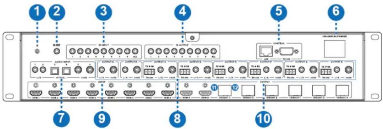
| Number | Name | Function descriptions |
| 1 | GND | The housing is connected to the ground. |
| 2 | IR EXT | If the front IR window of the unit is obstructed or the unit is installed in a closed area out of infrared line of sight, the IR receiver cable can be inserted to the “IR EXT” portto receiving the IR remote signal. |
| 3 | IR INPUT | Connect to IR receiver cable, the IR receive signal will emit to “IR OUT” port in the HDBaseT recevier. |
| 4 | IR OUTPUT | Connect to IR blaster cable, the IR transmit signal is from “IR IN” port in the HDBaseT receiver. |
| 5 | CONTROL port | LAN port: This port is the link for TCP/IP control and connects to an active Internet link by an RJ45 cable. |
| RS-232 port: Connect to a PC or control system by D-Sub 9-pin cable to control the product. | ||
| 6 | POWER input | Connect to 100~240V AC 50/60Hz power cable. |
| 7 | AUDIO INPUT | L/R, optical and coaxial audio input ports, connect to external audio source device such as a PC or DVD. |
| 8 | AUDIO / RS-232 OUTPUT | L/R and Coaxial audio output ports, connect to audio output device such as audio amplifier or speaker.RS-232 port, connect to a PC or control system by 3-pin phoenix connector cable to transmission command between Matrix and HDBaseT receiver. |
| 9 | HDMI INPUT | HDMI input port, connect to HDMI source device such as DVD or PS4 etc. |
| 10 | HDMI / HDBaseT OUTPUT | HDMI output port, connect to HDMI display device such as TV or monitor etc.HDBaseT port, connect to “HDBaseT IN” port in HDBaseT receiver with an CAT cable. |
| 11 | Connection Signal Indicator Lamp | ·Illuminate: Transmitter and Receiver are in good connection status.·Flashing: Transmitter and Receiver are in poor connection status.·Dark: Transmitter and Receiver are not connected. |
| 12 | Data Signal Indicator Lamp | ·Illuminate: HDMI signal with HDCP.·Flashing: HDMI signal without HDCP.·Dark: No HDMI signal. |
The following picture is HDBaseT port indicator lamp:

6. IR Remote
① : Power on the Matrix or set it to the standby
status.
② Input 1/2/3/4/5/6/7/8 button: Select input source button.

: Select the last or next input source button.
③ Output A/B/C/D/E/F/G/H: Select output source button.
All: Select all output source simultaneously. For example,
when you select the “All” button and then select input “1” button, at this time the input “1” source will output to all output device.

Operation instruction: You need to select output button first and then select input button to select output display corresponding input source.
The Matrix can also be controlled by using the IR remote. There are two ways to receive the IR remote signal.
The first way: The IR window is accepted the IR remote signal. The distance of the IR remote is the furthest 7 meters and angle is plus or minus 45 degrees. The diagram is shown as below:

The second way: If the front IR window of the Matrix is obstructed or the Matrix is installed in a closed area out of infrared line of sight, the IR receiver cable can be inserted to the “IR EXT” port to receiving the IR remote signal. The distance of the IR remote is the further 7 meters and the IR remote is directly faced to the IR receiver head. The picture is shown as below.

7. IR Control System
The matrix is not only a switcher but also an extender. It supports two-way IR control. When Matrix is connected HDBaseT receiver through Cat 6/6a/7 cable, you can
control further display device about the HDBaseT or input source device about location Matrix through IR signal transmission. For example, When Matrix is connected HDBaseT receiver through Cat 6/6a/7 cable, you can use the TV remote control in the matrix end to control further TV. At the same time, you can use the DVD remote control in the HDBaseT end to control location DVD. The connection
diagram is shown as below.
![graph TD A["Transmitter"] --> B["TV remote"] A --> C["IR Blaster"] A --> D["DVD"] A --> E["IR Blaster"] A --> F["Receiver"] A --> G["IR Blaster"] A --> H["DVD remote"] A --> I["IR Blaster"] A --> J["DVD remote"] A --> K["IR Blaster"] A --> L["DVD remote"] style A fill:#f9f,stroke:#333 style B fill:#…](/content/2026/05/1057333/images/20103c2cb30ae0d347a1609b672aee701834592f35ebb67db11375d5b1680412.jpg)
Figure 1: IR connection diagram

-
At Matrix End: The 3.5mm jack IR blaster cable is inset the IR OUTPUT port and the 3.5mm jack IR receiver cable is inset the IR INPUT port at the rear of the Matrix. If you want to control the HDMI input source device such as DVD, the IR blaster head is putted the DVD aside. IR receiver head receives the remote-control signal about the HDBaseT ‘s display device.
-
At HDBaseT Receiver End: The 3.5mm jack IR blaster cable is inset the IR OUT port and the 3.5mm jack IR receiver cable is inset the IR IN port at the rear of the HDBaseT Receiver. If you want to control the HDMI output
display device such as TV, the IR blaster cable is putted the TV aside. IR receiver head receives the remote control signal about the Matrix's input source device.
- Control method: You must pay attention to an important thing, the IR signal transmission follow the video signal between Matrix and HDBaseT. For example, The input source of the HDMI 1 port is switched to the HDBaseT C port display device. If HDMI 1 input port is connected a PS4 and HDMI OUT port in HDBaseT C receiver is connected a Sony TV. At Matrix end, the IR INPUT 1 port is controlled the Sony TV through the Sony remote control. At HDBaseT Receiver end, IR IN port is controlled the PS4 through the PS4 remote control. The IR blaster head should be putted the control device aside. Please see the following IR control diagram.
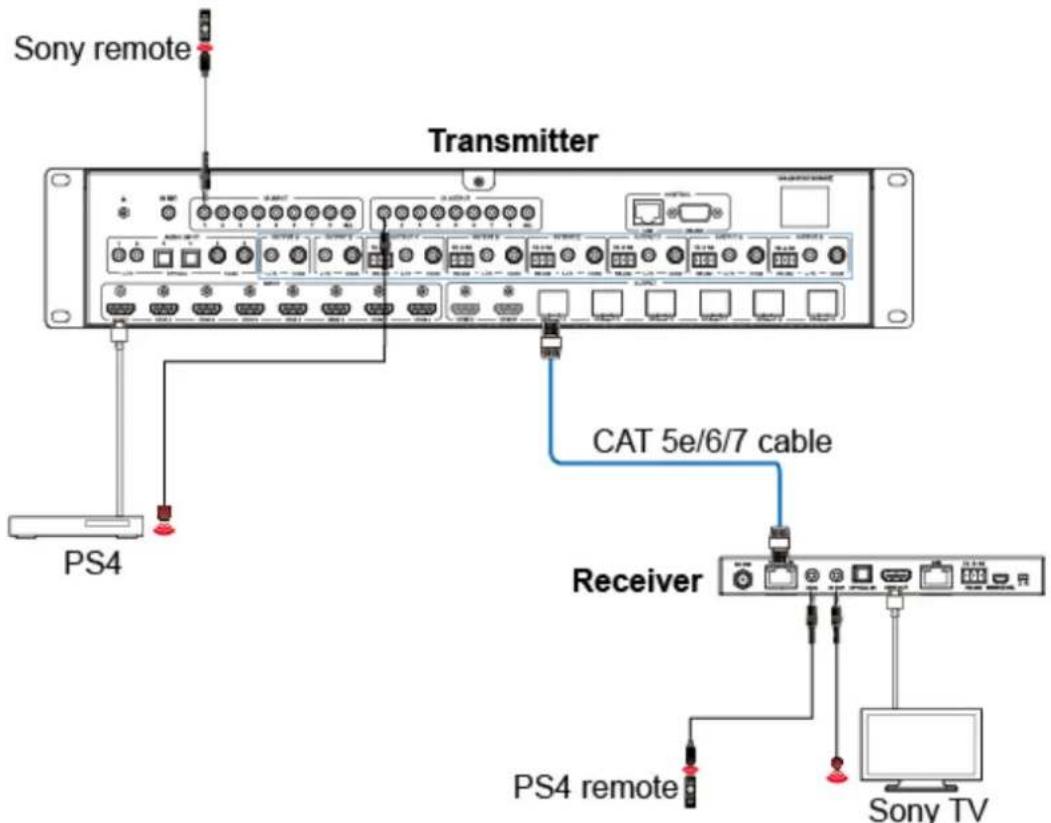
Figure 2: IR control diagram
8. IR Cable Pin Assignment
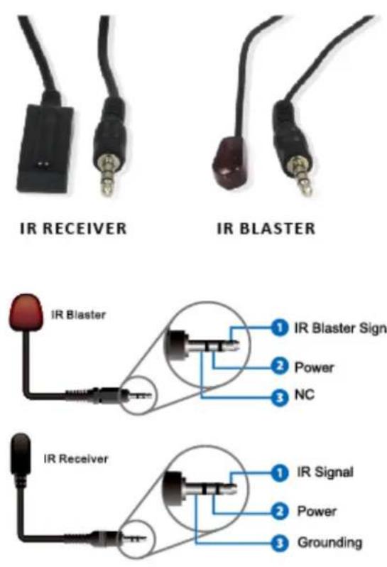
9. HDBaseT Receiver

| Number | Name | Function descriptions |
| 1 | POWER LED | Power LED indicator. |
| 2 | ARC LED | ARC LED status indicator. |
| 3 | ARC button | Turn on/off the ARC function. |
| 4 | DC 24V | Plug the 24V/1A adapter to AC wall outlet for power supply. |
| 5 | HDBaseT IN | HDBaseT input port, connect to “HDBaseT OUT” port in Matrix with an CAT able. |
| 6 | Connection Signal Indicator Lamp | ·Illuminate: Transmitter and Receiver are in good connectionstatus.·Flashing: Transmitter and Receiver are in poor connection status.·Dark: Transmitter and Receiver are not connected. |
| 7 | Data Signal Indicator Lamp | ·Illuminate: HDMI signal with HDCP.·Flashing: HDMI signal without HDCP.·Dark: No HDMI signal. |
| 8 | IR IN | Connect to IR receiver cable, the IR receive signal will emit to “IR OUTPUT” port in Matrix. |
| 9 | IR OUT | Connect to IR blaster cable, the IR transmit signal is from “IR OUTPUT” port in Matrix. |
| 10 | OPTICAL IN | Optical audio input port, connect to external audio source device such DVD. |
| 11 | HDMI OUT | HDMI output port, connect to HDMI display device such as TV or monitor etc. |
| 12 | LAN | Connect to a PC or laptop with an RJ45 cable to surf the internet. The net speed up to 100Mbps. Note: The HDBaseT cable cannot connect to the LAN port. Otherwise, the LAN port or the HDBaseT Receiver will be damage. |


| Number | Name | Function descriptions |
| 1 | POWER LED | Power LED indicator. |
| 2 | ARC LED | ARC LED status indicator. |
| 3 | ARC button | Turn on/off the ARC function. |
| 4 | DC 24V | Plug the 24V/1A adapter to AC wall outlet for power supply. |
| 5 | HDBaseT IN | HDBaseT input port, connect to “HDBaseT OUT” port in Matrix with an CAT able. |
| 6 | Connection Signal Indicator Lamp | ·Illuminate: Transmitter and Receiver are in good connectionstatus.·Flashing: Transmitter and Receiver are in poor connection status.·Dark: Transmitter and Receiver are not connected. |
| 7 | Data Signal Indicator Lamp | ·Illuminate: HDMI signal with HDCP.·Flashing: HDMI signal without HDCP.·Dark: No HDMI signal. |
| 8 | IR IN | Connect to IR receiver cable, the IR receive signal will emit to “IR OUTPUT” port in Matrix. |
| 9 | IR OUT | Connect to IR blaster cable, the IR transmit signal is from “IR OUTPUT” port in Matrix. |
| 10 | OPTICAL IN | Optical audio input port, connect to external audio source device such DVD. |
| 11 | HDMI OUT | HDMI output port, connect to HDMI display device such as TV or monitor etc. |
| 12 | LAN | Connect to a PC or laptop with an RJ45 cable to surf the internet. The net speed up to 100Mbps. Note: The HDBaseT cable cannot connect to the LAN port. Otherwise, the LAN port or the HDBaseT Receiver will be damage. |
| 13 | RS-232 | Connect to a PC or control system by 3-pin phoenix connector cable to transmission command between Matrix and HDBaseT receiver. |
| 14 | SERVICE SEL 1/2 | Service port, reserved port for manufacturer use. |
10. EDID Management
This Matrix has 19 factory defined EDID settings and 8 copy EDID mode. You can select defined EDID mode or copy EDID mode to input port through on-panel button or Web GUI.
On-panel button operation: On the initial OLED display, press the “MENU” button to enter function page. In “Select EDID” option, press the “Right” button to enter EDID setting and press the “Up” and “Down” button to select EDID mode. Then you need to press the “Right” button and the “Up” or “Down” button to copy the EDID to one input port. Finally, you need to press the “Right” button to confirm this operation.

Web GUI Operation: Please check “EDID page” in the “12. Web GUI User Guide”.
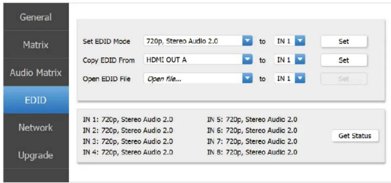
There are predefined EDID setting that you can select:
| EDID Mode | EDID Description |
| 1 | 720p, Stereo Audio 2.0 |
| 2 | 1080p, Stereo Audio 2.0 |
| 3 | 1080p, Dolby/DTS 5.1 |
| 4 | 1080p, HD Audio 7.1 |
| 5 | 1080i, Stereo Audio 2.0 |
| 6 | 1080i, Dolby/DTS 5.1 |
| 7 | 1080i, HD Audio 7.1 |
| 8 | 3D, Stereo Audio 2.0 |
| 9 | 3D, Dolby/DTS 5.1 |
| 10 | 3D, HD Audio 7.1 |
| 11 | 4K2K30_444, Stereo Audio 2.0 |
| 12 | 4K2K30_444, Dolby/DTS 5.1 |
| 13 | 4K2K30_444, HD Audio 7.1 |
| 14 | 4K2K60_420, Stereo Audio 2.0 |
| 15 | 4K2K60_420, Dolby/DTS 5.1 |
| 16 | 4K2K60_420, HD Audio 7.1 |
| 17 | 4K2K60_444, Stereo Audio 2.0 |
| 18 | 4K2K60_444, Dolby/DTS 5.1 |
| 19 | 4K2K60_444, HD Audio 7.1 |
| 20 | Copy HDMI OUT A |
| 21 | Copy HDMI OUT B |
| 22 | Copy HDBaseT OUT C |
| 23 | Copy HDBaseT OUT D |
| 24 | Copy HDBaseT OUT E |
| 25 | Copy HDBaseT OUT F |
| 26 | Copy HDBaseT OUT G |
| 27 | Copy HDBaseT OUT H |
11. Audio Matrix
The Matrix supports 6 sorts of external audio input in the AUDIO INPUT area, including analog 1, analog 2, spdif 1, spdif 2, coaxial 1 and coaxial 2. You can connect external audio source device such as DVD or PC.
In OUTPUT A\~OUTPUT H area, L/R and coaxial audio outputs are supported. The audio output for each box is the same. For example, L/R and coaxial audio output signal is the same in OUTPUT A. You can select 22 sorts of audio source through Web GUI control to these audio port output, including 8 sorts of HDMI input audio source, 8 sorts of ARC audio source and 6 sorts of external audio source. The audio control to see “12. Web GUI User Guide”. You can set the audio delay and adjust volume through Web GUI.
Notice: ARC audio can be outputted when the ARC switch is turned on.
In RS-232 port about matrix and receiver, this is a channel about transmission command between matrix and receiver. You can connect PC or another device such as HDMI Matrix in RS-232 port, and you can control the HDMI Matrix through the remote PC. The RS-232 is one-to-one transmission between Matrix and Receiver. For example, this is a transmission channel between the RS-232 of the OUTPUT C in Matrix and the RS-232 of the Receiver in HDBaseT C port.
The audio and RS-232 connection diagram is shown as below.

Figure 2: Audio and RS-232 connection diagram

Figure 3: 3-pin phoenix connector to USB
12. Web GUI User Guide
The Matrix can be controlled via Web GUI. You must know current Matrix IP address. The default IP address is 192.168.1.100. You can get the current IP address through on-panel. The LAN port of the Matrix connects directly a PC with an UTP cable. The “Figure 4” is the Web GUI connection diagram. Please check the following instruction.
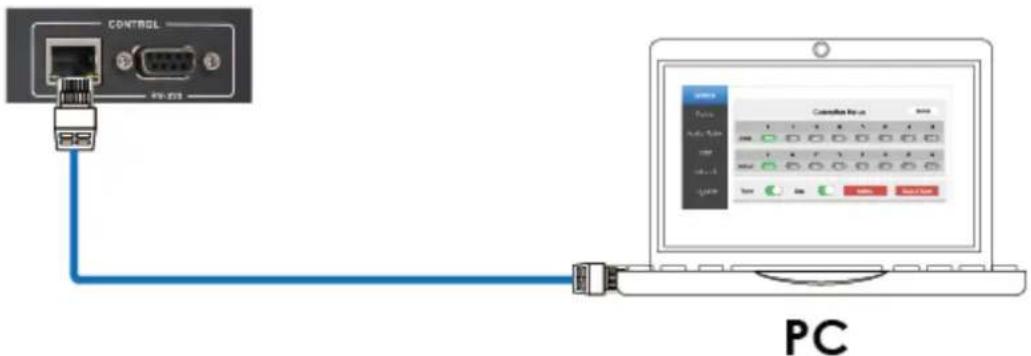
Figure 4: Web GUI connection diagram
The Matrix gets IP address via on-panel button. On the initial OLED display, you can press “Menu” button to enter function page. Then press “Up” or “Down” button to select function. When select the “View IP” function, then press the
“Right” button to check current IP address and DHCP status. In this moment, you can get current IP address.
Step 1: The LAN port connects directly PC with an UTP cable.
Step 2: On the PC, go to Control Panel > Network and Internet > Network
Connections > Local Area Connections, right click on it, choose Properties.

Double click Internet Protocol Version 4 (TCP/IPv4)
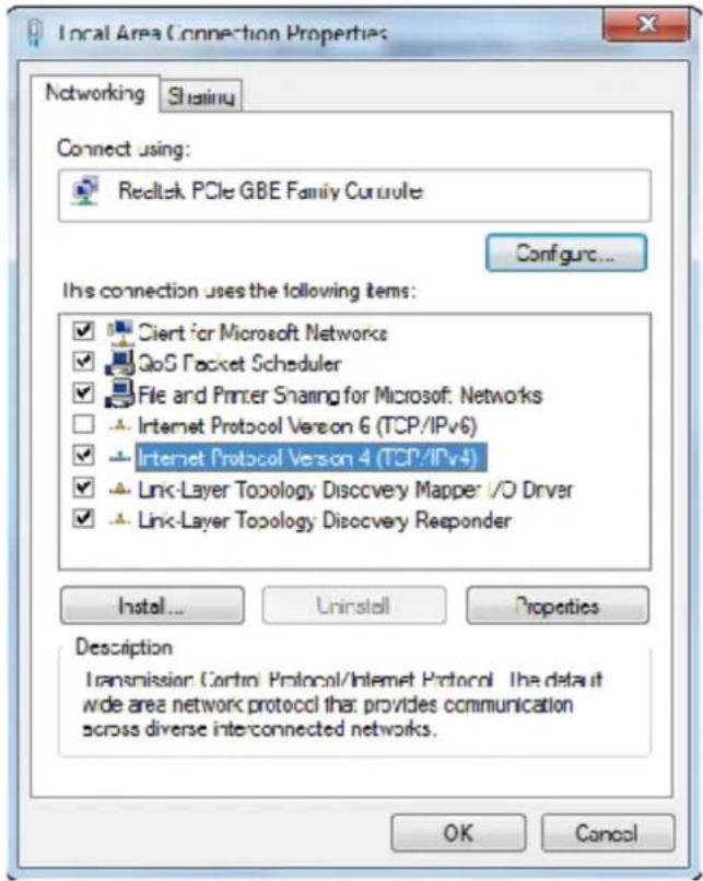
Choose “Use the following IP address”, input 192.168.1.200 as IP address, 255.255.
255.0 as Subnet mask, and then click on OK, click on OK again.

Notice: The IP address of the computer and Matrix should be in the same network segment. As the Matrix's IP address is 192.168.1.100, the computer's IP should be
192.168.1.X (X contains 1\~255 except 100).
Step 3: Input the IP address from front panel into your brower on the PC to enter Web GUI page, These pages are show as below.
General page

(1) Clicking the “Status” button will display current the Matrix input and output port status. The “Yes” sign has connected input or output source and “No” sign represents no connection.
Note: The Connection Status will display “Yes” sign when input and output source
is standby status or using status. Otherwise the Connection Status will display "No"
sign.
② Power switch. The product will work when turn on this switch. Otherwise, the product will standby. In standby status, it is invalid that you set any function. The product will go back to the previous function status when it is power on again.
③ Beep switch. Turn on this switch, pressing on-panel button in Matrix will have
voice. Close this switch, it will mute.
④ There will be a option frame when you click this button. Clicking the “Yes” button will reboot the product, after reboot the product and all functions will go back to the previous function status. Clicking the “No” button will close the option frame.
⑤ There will be a option frame when you click this button. Clicking the “Yes” button will set the product to factory reset. When the product has finished this setting, you need to login in the Web GUI again on the PC browser. At this time, all settings have been cleared. For example, input and output will one-to-one display and all audio embed display default, all audio outputs select the HDMI INPUT 1 etc.
It is important that the IP address will go back to default value (192.168.1.100). Clicking the “No” button will close the option frame.
Matrix page
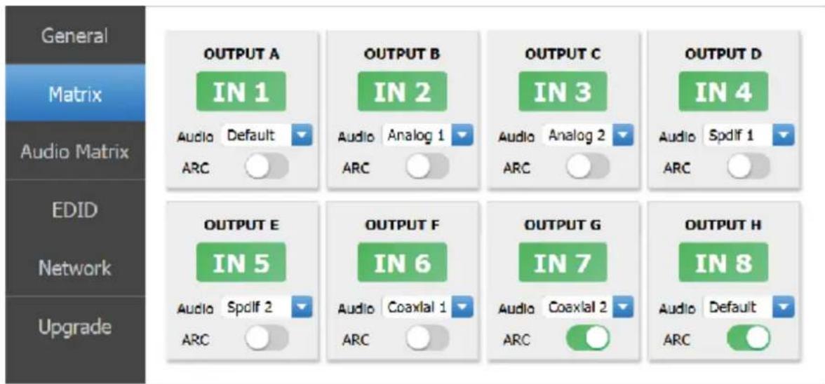

Picture 1

Picture 2
OUTPUT A: There will be a option frame when you click the green area about
OUTPUT A port. Please see above “Picture 1”. You can select an input source to OUTPUT A output.
Audio: There will be a drop-down frame when you click the blue arrow area. Please see above “Picture 2”. You can select default input source audio or embed external
input source audio including Analog 1, Analog 2, Spdif 1, Spdif 2, Coaxial 1, Coaxial 2 to OUTPUT A output.
Note: The “Default” audio is from input signal source audio. The embed audio is from external input source audio.
ARC Switch: Turn on or off the ARC function of the OUTPUT A.
Note: The other output ports have similar to function about the OUTPUT A.
Audio Matrix page

Picture 2
Picture 1
OUTPUT A: There will be a drop-down frame when you click the blue arrow area. Please see “Picture 1”. You can select an audio source to OUTPUT A audio output.
Note: HDMI INPUT 1\~8 is from HDMI input signal source audio. ARC 1\~8 is from display device return audio. Analog 1, Analog 2, Spdif 1, Spdif 2, Coaxial 1, Coaxial 2 is from external input source audio.
Delay: Set the OUTPUT A audio delay time. The default delay is 0ms.
(The delay range is 0\~2000ms)
Vol: There will be a volume adjust line when you click the green area. Please see "Picture 2". The default volume is 33. (The volume range is 0\~100)
Note: The others OUTPUT ports have similar function about OUTPUT A.
EDID page


Picture 2
Picture 3
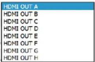
Set EDID Mode: You will see the EDID mode list and input port frame when you click the blue arrow area. Please see Picture 1 and Picture 2. You need to select an EDID mode to an input source. Then click the “Set” button. At this time, the EDID mode has been send to the input source.
Copy EDID From: You will see the HDMI output port and input port frame when you click the blue arrow area. Please see Picture 3 and Picture 2. You need to select an HDMI OUTPUT port to an input source. Then click the Set button. At this time, copy the EDID from the output device has been send to the input source.
Open EDID File: The function can not be used.
Get Status button: Clicking the “Get Status” button will display each input
source
EDID status currently.
Network page

Network Configuration
◆ In DHCP open status:
DHCP switch: Obtain automatically the network configuration information, including IP address, Subnet, Gate.
◆ In DHCP close status:
DHCP switch: If the DHCP switch has been closed, you can set IP, Subnet, Gate address. You must pay attention to the Gate address and the IP address in the same network segment. IP address and Gate address can not the same in the last address. You need not to change the Subnet address. In this moment, click the “Save Changes” button to save current status information. For example, please check the following page.
Note: If you have set a new IP address and click the “Save Changes” button. You
have changed the IP address, and you can continue use Web GUI function. But next time you connect Web GUI, you need to check current the IP address on the front panel. The IP address will recover default 192.168.1.100 when the product is set factory reset.
Net Status button: Clicking this button will refresh currently network configuration information to display in Status Log.
Status Log: Display the Net configuration information.
Clear button: Clear the Status Log information.

Upgrade page

Upgrade: Select bin. upgrade file, then click the “Upgrade” button to upgrade.
At this time, you will see a upgrade progress. The upgrade has finished when the upgrade progress up to 100%.
Notice: This Upgrade port can only upgrade MCU.
13. ASCII control command
The product also supports ASCII control. You need to a RS-232 male head with DB9 transfer USB male head serial cable. The RS-232 head of the serial cable is connected the RS-232 control port with DB 9 at the rear of the Matrix, and the USB head of the serial cable is connected a PC. Open any of a Serial Command tool on PC such as “Docklight” to send command to control the Matrix.
The following is shown RS-232 pin's definition and connection way.

9-Pin male DIN interface
Pin's definition
| PIN | SIGNAL | DESCRIPTION |
| 1 | DCD | Data Carry Detect |
| 2 | SIN | Serial In or Receiver Data |
| 3 | SOUT | Serial Out or Transmit Data |
| 4 | DTR | Data Terminal Ready |
| 5 | GND | Ground |
| 6 | DSR | Data Set Ready |
| 7 | RTS | Request To Send |
| 8 | CTS | Clear To Send |
| 9 | RI | Ring Indicate |

Double click the “Docklight” shortcut icon. Please see the following picture 1.

Picture 1
You will see the following page.
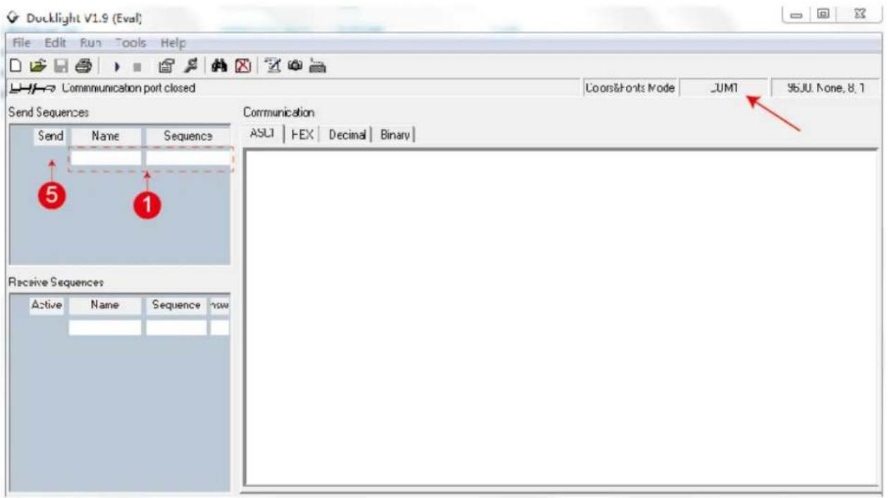
Click the “COM” area, there will be a “Project Settings” page. Choose the COM portto connect the software, and you need to setting the Baud Rate, Data Bits, Parity, Stop Bits and then click the “OK” button. Please see the following page.

Double click the “label 1” blank area. You will see the following page. At “label 2”, you can explain sequence definition. At “label 3”, you need to choose the sequence mode. At “label 4”, you can input the RS-232 command of the product. Then click the “OK” button.
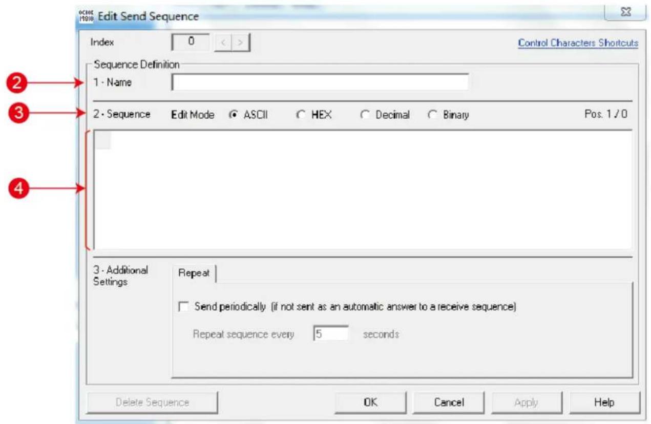
Finally, you need to click “label 5” button to send the command.
The ASCII list about the product is shown as below.
| ASCII Command | ||||
| Serial port protocol. Baud rate: 19200, Data bits: 8bit, Stop bits:1, Check bit: 0 | ||||
| x - Parameter 1y - Parameter 2! - Delimiter | ||||
| NO. | RS-232 Command | Function description | Feedback | Comments |
| 1 | s x av y! | Switch x channel input to y channel output | av x -> y | |
| 2 | s x all! | Switch x channel input to all channel output | x to all | |
| 3 | r all out! | Get the corresponding switch state between all output port and the input port | AV 1 -> 1, AV 2 -> 2AV 3 -> 3, AV 4 -> 4 | Input 1 route to output1, Input 2 route to output2, etc. |
| 4 | r out 1! | Get the corresponding switch state between the x output port and the input port | AV x -> x | |
| 5 | s ptp! | One way corresponding between input and output channels. | ptp | |
| 6 | r link in x! | Get the connection status of the x input port | HDMI IN x: connect | x-port,disconnected/connect |
| 7 | r link out x! | Get the connection status of the x output port | HDMI OUT x: disconnect | x-out port, disconnected/connect |
| 8 | r link in all! | Get the connection status of all input port | HDMI IN x: connect/disconnect | x-connected/disconnected |
| 9 | r link out all! | Get the connection status of all input port | HDMI OUTx: connect/disconnect | x-connected/disconnected |
| 10 | s x off! | Turn off the x output channel | out x off | |
| 11 | s x on! | Turn on the x output channel | out x on | |
| 12 | s all off! | Turn off all the output channel | all out off | |
| 13 | s all on! | Turn on all the output channel | all out on | |
| NO. | RS-232 Command | Function description | Feedback | Comments |
| 14 | s edid x c y! | Copy the display EDID on the x output port to the y input port | copy edid from output y to input x | |
| 15 | s edid x d y! | Copy the built-in EDID number y to the x input port | use default edid y to input x | |
| 16 | s edid all c y! | Copy the display EDID on the x output port to all inputs | copy edid from output y to all inputs | |
| 17 | s edid all d y! | Copy the built-in EDID number y to all input ports | use default edid y to all input | |
| 18 | s edid default! | Restore the default EDID (1080P 2) to each input port | edid default | |
| 19 | r edid x! | Get the Edid state of the x input port | IN1: 1080p, Stereo Audio 2.0 | |
| 20 | r edid all! | Query the EDID status of all ports | IN1: 1080p, Stereo Audio 2.0IN2: 1080p, Stereo Audio 2.0IN3: 1080p, Stereo Audio 2.0IN4: 1080p, Stereo Audio 2.0IN5: 1080p, Stereo Audio 2.0IN6: 1080p, Stereo Audio 2.0 | check EDID list |
| 21 | s x hdcp 2.2! | Force opening hdcp of the x output port | out x hdcp 2.2 | |
| 22 | s x hdcp off! | Force shutdown hdcp of the x output port | out x hdcp off | |
| 23 | s x hdcp auto! | Automatic management hdcp of x output port | out x hdcp auto | |
| 24 | s all hdcp off! | Force shutdown hdcp of the all output port | all out hdcp off | |
| 25 | s all hdcp auto! | Automatic management hdcp of all output port | all out hdcp auto | |
| 26 | r hdcp in x! | Get the Hdcp state of the x input port | a hdcp in | |
| 27 | r hdcp out x! | Get the Hdcp state of the x output port | a hdcp out | |
| 28 | r hdcp all in! | Query all input port HDCP status | a hdcp in all | |
| 29 | r hdcp all out! | Query all output port HDCP status | a hdcp out all | |
| 30 | s x audio y! | Set up the audio source of x output channel | set audio output x from y | |
| 31 | s x audio delay y! | Set up the delay of x output channel's audio | set audio output x delay y | |
| 32 | s x audio vol y! | Set up the volume of x output channel's audio | set audio output x vol y | |
| 33 | s x hdmi audio y! | The audio of the x output port is embedded from the y channel | set hdmi x audio input from y | |
| 34 | r hdmi audio x! | Get audio embedding channel for x output port | a hdmi out x audio y | |
| 35 | r audio delay x! | Get audio delay for x output port | a audio out x delay y | |
| 36 | r audio src x! | Get audio source for x output port | a audio out x from y | |
| NO. | RS-232 Command | Function description | Feedback | Comments |
| 37 | r audio vol x! | Get audio volume for x output port | a audio out x vol y | |
| s x arc on! | Turn on arc of x channel | out x arc on | ||
| s x arc off! | Turn off arc of x channel | out x arc off | ||
| s arc all on! | Turn on arc of all channel | all out arc on | ||
| s arc all off! | Turn off arc of all channel | all out arc off | ||
| r arc x! | Get the corresponding arc state x output channel | out x arc off/on | ||
| 38 | s beep on! | Open buzzer function | beep on | |
| 39 | s beep off! | Cancel buzzer function | beep off | |
| 40 | r beep! | Get the switch state of the buzzer | a beep on | beep state reports off after a reboot but still works |
| 41 | s lock on! | Panel lock | lock on | |
| 42 | s lock off! | Panel unlock | lock off | |
| 43 | r lock! | Get the status of the panel key lock | a lock on | |
| 44 | s power on! | Machine boot | power on | |
| 45 | s power off! | Machine shutdown | power off | |
| 46 | r power! | Query power state | a power on | |
| 47 | s rboot! | Machine reboot | rboot | |
| 48 | s factory reset! | Restore factory settings | factory reset | |
| 49 | r type! | Query matrix model | a HDM-B88H100 | |
| 50 | r version! | Query software version | a {aa.bb}-{aa.bb}-{aa.bb} | {Boot version}-{MCU version}-{HDMI version} |
| 51 | r status! | Query the status of the entire machine | a {aa.bb}-{aa.bb}-{aa.bb.cc.dd} | {MCU version}-{model type}-{IP address} |
| 52 | s dhcp off! | Set up network module using static IP | ip mode Static | |
| 53 | s dhcp on! | Set up network modules using dynamic IP | ip mode DHCP | |
| 54 | r dhcp! | Get the Dhcp status of the network module | a ip mode DHCP | |
| 55 | s ip addr a.b.c.d! | Set the IP address of the network board | {a}.{b}.{c}.{d} | |
| 56 | s mac addr a-b-c-d-e-f! | Set the MAC address of the network board | {a}-{b}-{c}-{d}-{e}-{f} | Doesn't allow letters |
| 57 | s subnet a.b.c.d! | Setting subnet mask of network module | {a}.{b}.{c}.{d} | |
| 58 | s gateway a.b.c.d! | Set up network module gateway | {a}.{b}.{c}.{d} | |
| 59 | s port 8000! | Set control port at 8000 | 8000 | |
| 60 | s network enable! | When configuring network modules,execute all the commands you need to configure first and then execute this command to reboot network modules | ||
| 61 | r ip addr! | Get the IP address of the network board | a {a}.{b}.{c}.{d} | |
| 62 | r mac addr! | Get the MAC address of the network board | a {a}-{b}-{c}-{d}-{e}-{f} | |
| 63 | r subnet! | Get the subnet mask of the network board | a {a}.{b}.{c}.{d} | |
| 64 | r gateway! | Get the gateway of the network board | a {a}.{b}.{c}.{d} | |
| 65 | r port! | Get network port number | a 8000 | |
| 66 | s net name *****! | Set the name of the network module | ****** | |
| 67 | r net name! | Get the name of the network module | a ***** |
14. Application Example
![graph TD subgraph Top A["DVD or Blu-ray Player"] --> B["TV remote"] C["Audio amplifier A"] --> D["TV remote"] E["Computer"] --> F["2.01 speakers"] G["Internal Modem or Router"] --> H["RS-232 Blu-ray PC or Inverter"] I["Computer"] --> J["2.01 speakers"] K["TX"] --> L["180-265V AC/6A/48KZ"] end subgra…](/content/2026/05/1057333/images/e34a2d643c92e9f6baec14d7143a226b47a835a55af2d63b0d6bf7a0f84c4211.jpg)
15. FAQ
- Q: Does this product require an HDMI and CAT line length for the connection interface?
A: According to line length test. When the resolution is 1080p@60Hz 12 bit, and the HDMI input / output line length up to 3m / 15m. When the resolution is 4K@24Hz, and the HDMI input / output line length up to 3m / 10m. When the resolution is 4K@60Hz, and the HDMI input / output line length up to 3m.
The use of “Premium High-Speed HDMI” cable is highly recommended.
When the resolution is 1080p@60Hz 12 bit / 4K@60Hz YUV 4:4:4, and the CAT6 cable extends distance up to 100m / 90m.
After Sales-Service
If problems arise when operating the device, please refer to this user manual. Any transport costs are borne by the users during the warranty.
-
Product Limited Warranty: We warrant that products will be free from defects in materials and workmanship for three years, which starts from the first day the product exits warehouse. (Make note of the serial number on the product) Proof of purchase in the form of a bill of sale or receipted invoice MUST be presented to obtain warranty service.
-
What the warranty does not cover:
-
Warranty expiration.
- Factory applied serial number has been altered or removed from the product.
- Damage, deterioration or malfunction caused by:
• Normal wear and tear - Use of supplies or parts not meeting our specifications
- No certificate or invoice as the proof of warranty.
-
The product model showed on the warranty card does not match with the model of the product for repairing or had been altered.
-
Damage caused by force majeure.
• Servicing not authorized - Any other causes which does not relate to a product defect
-
Delivery, installation or labor charges for installation or setup of the product
-
Technical Support: Email or call our after-sales department if there are any problems or any unanswered questions. Please inform us the following information
about your cases:
• Product version and name.
• Detailed failure situations.
Remarks: For any questions or troubleshooting please contact your local
distributor or email support@kanexpro.com or call 888-975-1368
Warranty
A. LIMITED WARRANTY
KanexPro™ warrants that (a) its products (the "Product") will perform greatly in agreement with the accompanying written materials for a period of 36 months (3 full years) from the date of receipt and (b) that the product will be free from defects in materials and workmanship under normal use and service for a period of 3 years.
B. CUSTOMER REMEDIES
KanexPro's entire liability and Customer's exclusive remedy shall be, at KanexPro option, either return of the price paid for the product, or repair or replacement of the Product that does not meet this Limited Warranty and which is returned to KanexPro with a copy of customers' receipt. This Limited Warranty is void if failure of the Product has resulted from accident, abuse, or misapplication. Any replacement Product will be warranted for the remainder of the original warranty period of 3 years, whichever is longer.
C. NO OTHER WARRANTIES
To the maximum extent permitted by applicable law, KanexPro disclaims all other warranties, either express or implied, including, but not limited to implied warranties of merchantability and fitness for a purpose, regarding the product and any related written materials. This limited warranty gives customers specific legal rights. Customers may have other rights depending on the jurisdiction.
D. NO LIABILITY FOR DAMAGES
To the maximum extent permitted by applicable law, in no event shall KanexPro be liable for any damages whatsoever (including without limitation, special, incidental, consequential, or indirect damages for personal injury, loss of business profits, business interruption, loss of business information, or any other pecuniary loss) arising out of the use of or inability to use this product, even if KanexPro has been advised of the possibility of such damages
KanexPro™
Brea California,
www.kanexpro.com
- THANK YOU FOR PURCHASING THIS PRODUCT
- SURGE PROTECTION DEVICE RECOMMENDED
- TABLE OF CONTENTS
- INTRODUCTION
- FEATURES
- OUTPUTS
- PACKAGE CONTENTS
- SPECIFICATIONS
- OPERATION CONTROLS AND FUNCTIONS
- 5.1 FRONT PANEL
- 5.2 REAR PANEL
- IR REMOTE
- IR CONTROL SYSTEM
- IR CABLE PIN ASSIGNMENT
- HDBASET RECEIVER
- EDID MANAGEMENT
- AUDIO MATRIX
- WEB GUI USER GUIDE
- GENERAL PAGE
- MATRIX PAGE
- NETWORK PAGE
- NETWORK CONFIGURATION
- UPGRADE PAGE
- ASCII CONTROL COMMAND
- APPLICATION EXAMPLE
- FAQ
- AFTER SALES-SERVICE
- WARRANTY
- LIMITED WARRANTY
- CUSTOMER REMEDIES
- NO OTHER WARRANTIES
- NO LIABILITY FOR DAMAGES
- KANEXPRO™
Brand : KanexPro
Model : MX-HDBT8X818G
Category : Network switch