
HF7BEQ - Audio Equalizer Hifonics - Free user manual and instructions
Find the device manual for free HF7BEQ Hifonics in PDF.


| Product Type | Graphic Equalizer / Signal Processor |
| Brand | Hifonics |
| Model | HF7BEQ |
| Dimensions (W x H x D) | 7.0 x 1.6 x 5.5 inches (177 x 40 x 140 mm) |
| Weight | 1.2 lbs (0.54 kg) |
| Power Supply Voltage | 12 V DC (negative ground) |
| Number of Bands | 7 bands |
| Frequency Range | 20 Hz – 20 kHz |
| Equalization Range per Band | ±12 dB |
| Input Sensitivity | 200 mV – 6 V |
| Output Voltage | Up to 7 V RMS |
| Signal-to-Noise Ratio | > 100 dB |
| Total Harmonic Distortion | < 0.01% |
| Chassis Material | Aluminum alloy |
| Controls | Rotary knobs for each band, front/rear fader, subwoofer level, bass boost, and remote input |
| Inputs / Outputs | RCA inputs (2-channel), RCA outputs (front, rear, subwoofer) |
| Additional Features | Subwoofer crossover (low-pass filter), bass boost at 40 Hz, remote bass level control port |
| Installation | In-dash or under-seat mounting; includes mounting brackets and hardware |
| Maintenance | Clean with dry cloth; avoid moisture and extreme temperatures |
| Safety | Fuse rating 1 A (built-in); disconnect battery before installation |
| Spare Parts / Repairability | Replacement knobs, RCA connectors, and fuse available; service by qualified technician |
| Included Accessories | Mounting screws, remote bass knob (optional), user manual |
Frequently Asked Questions - HF7BEQ Hifonics
User questions about HF7BEQ Hifonics
0 question about this device. Answer the ones you know or ask your own.
Ask a new question about this device
Download the instructions for your Audio Equalizer in PDF format for free! Find your manual HF7BEQ - Hifonics and take your electronic device back in hand. On this page are published all the documents necessary for the use of your device. HF7BEQ by Hifonics.
USER MANUAL HF7BEQ Hifonics
Thank you for purchasing the HIFONICS HF7BEQ 7-Band Equalizer/ two-way crossover. This unit has both a pre-amp equalizer and crossover to provide the multi-speaker system of your vehicle with improved sound performance. Please read the entire manual to ensure proper connections and application.

CAUTION

Always consider consulting a professional audio installer before installing any audio components. Be careful and take your time. Do not let wires make contact with metal edges or hot engine components.
Features
• ILLUMINATED BLUE CONTROL KNOB LEDS
- LOW AND HIGH LEVEL AUDIO INPUTS (SPEAKER LEVEL)
• DESIGNATED SUBWOOFER UNBALANCED OUTPUT
- SUBWOOFER X-OVER FREQUENCY CONTROL
- INPUT LEVEL CONTROL ADJUSTMENT
- FADER CONTROL
• HALF DIN CHASSIS SIZE
- MOUNTING HARDWARE (INCLUDED)
• SEVEN EQUALIZATION BANDS EACH ADJUST +/- 12dB
Prior to mounting, connect the wires to ensure proper operation.
MOUNTING
- Select the desired mounting location, either under the dash or in the dash. Make sure that there is adequate depth for the HF7BEQ.
- Use the mounting brackets and hardware provided. Make sure there is proper clearance for the mounting bracket screws when attaching under the dash. Use caution to ensure there are no wiring harnesses behind the dash panel (where the mounting screws are fastened).
- Route the power, ground, and remote wires away from moving parts to prevent pinching or shortened wires.
WIRING
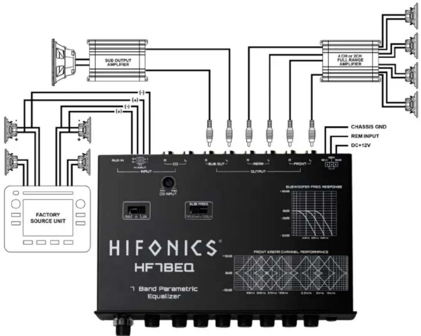
- Power Wire: The power wire should connect to a constant or switched +12 volt source with a (2 Amp) in-line fuse. We recommend that you use the radio constant or switch +12 volt source.
- Gound Wire: Connect the ground wire to a clean chassis ground point. Be sure to remove all paint and primer to expose clean metal. Use a ring terminal and lock or star washer to secure the ground wire.
- Remote Wire: The remote wire should be connected to the source until remote or antenna wire that provides +12 volts when the source unit is "on" and 0 volts when the source unit is turned "off."
Functions & Operations
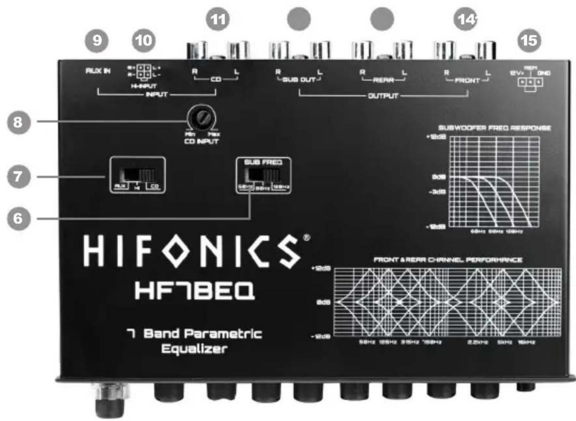
1 Volume Control: The audio level (volume) can be increased or decreased with this illuminated VOLUME control knob.
2 Fader Control: Allows to control the front and rear output levels.
3 Subwoofer Control: The Subwoofer output level is controlled by the SUB illuminated knob.
4 Equalization: Seven bands (50Hz, 125Hz, 315Hz, 750Hz, 2.2kHz, 6kHz,& 16kHz) each frequency adjustable +/- 12dB
5 LED Selection: Turn on/off front illumination
6 Subwoofer Frequency Switch: This switch allows you to choose between three different frequency settings (60Hz, 80Hz, 120Hz)
7 Input Selection: Allows to select input CD (RCA Input), High Level Input, AUX
8 Input Level (Gain) Control (CD Input Only): This input level control can be adjusted to match the source unit line-level sensitivity.
9 AUX: 3.5mm jack connected to (Phone/MP3 player) have L & R unbalanced inputs which are directly routed to the internal EQ and passed though to the outputs. Each input can be chosen independently by the input selector switch.
10 High Level Input: Speaker Level
11 CD (RCA Input): Input from the source unit (radio/CD player) have L & R unbalanced inputs which are directly routed to the internal EQ and passed though outputs. Each input can be chosen independently by the input selector switch.
Subwoofer Outputs: The subwoofer left & right are low pass outputs are connected to the subwoofer amplifier(s) inputs.
13 Rear Outputs: This is high pass output to be connected to the amplifier(s) inputs for rear speakers.
14 Front Outputs: This is high pass output to be connected to the amplifier(s) inputs for front speakers.
15 Power Connectors: This is the input jack that supplies power, ground and remote.
The 12+ Volt Terminal Connects to either constant +12 volts or to an accessory switched +12 volt source. The radio power wire is preferred source. (This is a fused power wire).
The Ground Terminal Connect to chassis ground.
The Remote Terminal Connect to the source unit remote or antenna output wire that provides +12 volts when the source unit is “on” and 0 volts when the source unit is turned “off.”
Functions & Operations

Aftermarket Unit Setup

flowchart
graph TD
    A["PHONE OR MP3 PLAYER"] --> B["SOURCE UNIT"]
    B --> C["RUX IN"]
    C --> D["GPIO L"]
    D --> E["INPUT"]
    E --> F["R"]
    F --> G["CO L"]
    G --> H["R"]
    H --> I["SUB OUT"]
    I --> J["OUTPUT"]
    J --> K["R"]
    K --> L["REAR L"]
    L --> M["R"]
    M --> N["FRONT L"]
    N --> O["10V GND"]
    O --> P["DC+12V IGNITION (REM) CHASSIS GND"]
    P --> Q["SUBWOOPER FRED RESPONSE"]
    Q --> R["-12dB 0dB -2dB 5dB-12 6dB-12 12dB-12"]
    R --> S["FRONT & REAR CHANNEL PERFORMANCE"]
    S --> T["-12dB 0dB -2dB 5dB-12 6dB-12 12dB-12"]
    T --> U["FRONT & REAR CHANNEL PERFORMANCE"]
Factory Unit Setup
flowchart
graph TD
    A["FACTORY SOURCE UNIT"] --> B["SUB OUTPUT AMPLIFIER"]
    B --> C["4 CH or 2CH FULL RANGE AMPLIFIER"]
    C --> D["CHASSIS GND"]
    C --> E["REM INPUT"]
    C --> F["DC+12V"]
    B --> G["RUX IN"]
    B --> H["INPUT"]
    G --> I["HIFONICS HF7BEQ"]
    H --> J["SUB OUT"]
    H --> K["REAR"]
    H --> L["FRONT"]
    I --> M["SUBWOOFER PREG RESPONSE"]
    J --> N["FRONT & REARR CHANNEL PERFORMANCE"]
    K --> O["FRONT & REARR CHANNEL PERFORMANCE"]
    style A fill:#f9f,stroke:#333
    style B fill:#ccf,stroke:#333
    style C fill:#ccf,stroke:#333
    style D fill:#dfd,stroke:#333
    style E fill:#dfd,stroke:#333
    style F fill:#dfd,stroke:#333
    style G fill:#dfd,stroke:#333
    style H fill:#dfd,stroke:#333
    style I fill:#dfd,stroke:#333
    style J fill:#dfd,stroke:#333
    style K fill:#dfd,stroke:#333
    style L fill:#dfd,stroke:#333
    style M fill:#dfd,stroke:#333
    style N fill:#dfd,stroke:#333
    style O fill:#dfd,stroke:#333
Diagnostics & Trouble Shooting
The key to finding the problem in a troubled sound system is to isolate parts of that system in a logical fashion to track down the fault and correct the issue.
The diagnostic system will not shut down the crossover or the amplifier(s), although the amplifier(s) own protection circuitry may shut the amplifier(s) down, should a fault status occur. You will need to consult the owners manual for that particular amplifier.
| Low Output Power | 1) Check that level controls have been set up properly.2) Make sure that the battery voltage, as measured at the amplifier(s) and crossover +12 volt and ground terminals, is 11 volts or more.3) Check all +12 volt and ground connections. |
| Fuses Blowing | 1) Insure that the voltage to the unit does not exceed 15 volts.2) A short on the main +12 volt cable from the battery to the vehicle chassis will cause the main fuse to blow.3) If the HF7BEQ is blowing fuses continually with only +12 volt, ground and remote leads connected, the unit may be faulty. |
| Fuses Blowing | 1) Check all fuses.2) Check all connections.3) Measure the +12 volt and remote turn on voltages at the amplifier(s) and crossover terminals. If these are nonexistent or low, take voltage measurements at fuse holders, distribution blocks, the head unit's +12 volt, and remote leads to localize the problem. |
| Hiss, or White Noise | 1) High levels of white noise usually occur when level controls are turned up too high – reduce the levels until the noise is no longer present.2) Another problem that can cause excessive hiss, is a noisy head unit – unplug the crossover input RCA's, and if the hiss level reduces, the source unit is at fault. |
| Electrical Interference | The inside of an automobile is a very hostile electrical environment. The multitude of electrical systems, such as the ignition system, alternator, fuel pumps, and air conditioners, create radiated electrical fields, as well as noise on the +12 volt supply and ground. To try and eliminate this noise, run a wire from the radio ground wire to the ground input on the equalizer. |
Ticking or Whine that changes with engine RPM
1) This problem could be caused by radiation pickup of RCA cables that are too close to a fuel pump or a distributor.
2) Check that the head unit ground is connected straight to the vehicle chassis and does not use factory wiring for ground.
3) Try to supply the head unit with a clean +12 volt supply directly from the battery +, instead of using a supply from the in-dash wiring/fusebox.
Constant Whine
This type of noise can be more difficult to pinpoint, but is usually caused by some kind of instability, causing oscillations in the system.
1) Check all connections, (especially for good grounds).
2) Make sure that no speaker leads are shorting to exposed metal on the vehicle chassis.
3) RCA cable are notorious for their problematic nature, so check that these are good, especially the shield connections.
Specifications
| OUTPUT CHANNELS (LEFT/RIGHT) FRONT/REAR/SUBW/OOFER | |
| INPUT CHANNELS (LEFT/RIGHT) RCA/CD, High Level, AUX 3.5mm | |
| INPUT RANGE OF GAIN CONTROL (dB) >40 | |
| MAXIMUM INPUT VOLTAGE (V) >10 | |
| INPUT IMPEDANCE (K-OHMS) >20 | |
| MAXIMUM OUTPUT VOLTAGE >9 | |
| VOLUME GAIN (dB) >85 | |
| -3dB LOW PASS FREQUENCY (Hz) 60>80>120 | |
| LOW PASS/HIGH PASS SLOPE/OCTAVE 12 | |
| EQUALIZATION FREQUENCIES (Hz) 50,125,315,750,2.2kHz,6kHz,16kHz | |
| EQUALIZATION CYT OR BOOST (dB) 12 | |
| DISTORTION AT 1kHz - 1V (%) .01 | |
| CHANNEL SEPARATION AT 1kHz (dB) >80 | |
| SIGNAL TO NOISE RATIO (dB) >100 | |
| FREQUENCY RESPONSE (Hz) (-1dB) 10-50K | |
Visit Hifonics.com
WARRANTY
Maxxsonics USA Inc. warrants this product, to the original consumer purchaser, to be free from defects in material and workmanship for a period of one (1) year from the date of purchase. Maxxsonics USA Inc. will, at its discretion, repair or replace defective products during the warranty period. Components that prove to be defective in materials and workmanship under proper installation use must be returned to the original authorized Maxxsonics USA Inc. retailer from where it was purchased. A photocopy of the original receipt must accompany the product being returned. The costs associated with removal, re-installation, and freight are not the responsibility of Maxxsonics USA Inc. This warranty is limited to defective parts and specifically excludes any incidental or consequential damages connected therewith. To view the full warranty, please visit the website.
Hifonics products are designed and engineered in the USA by
MAXXSONICS®
Brand : Hifonics
Model : HF7BEQ
Category : Audio Equalizer