BOSS ATVB95LED - Audio System

ATVB95LED - Audio System BOSS - Free user manual and instructions

Find the device manual for free ATVB95LED BOSS in PDF.

📄 1 pages English EN Download 💬 AI Question 10 questions ⚙️ Specs
Notice BOSS ATVB95LED - page 1
Pick your language and provide your email: we'll send you a specifically translated version.
Product Type Car Audio Receiver
Model ATVB95LED
Brand BOSS
Dimensions (W x H x D) 7.2 x 2.0 x 6.5 inches (182 x 50 x 165 mm)
Weight 2.2 lbs (1 kg)
Power Supply 12V DC (negative ground)
Power Output 4 x 50 Watts (RMS)
Display LED backlit LCD
Bluetooth Yes, for hands-free calling and audio streaming
USB Input Yes, for MP3/WMA playback and device charging
AUX Input Front 3.5mm
Radio Tuner AM/FM with 30 presets
Audio Format Support MP3, WMA, WAV
Equalizer 7-band graphic EQ
Remote Control Included
Security Code Yes, programmable anti-theft
Maintenance Clean with dry soft cloth; avoid liquids
Safety Fuse protection on power wire
Spare Parts Contact BOSS customer service

Frequently Asked Questions - ATVB95LED BOSS

How do I pair my phone via Bluetooth?
Turn on the unit and set to Bluetooth mode. On your phone, search for BOSS ATVB95LED and pair. Default PIN is 0000 if prompted.
Why is the display not turning on?
Check the vehicle's fuse and the unit's inline fuse. Ensure the ignition is in ACC or ON position. If still off, verify wiring connections.
How do I reset the unit?
Press the reset button on the front panel with a pointed object. Alternatively, disconnect the battery for 10 seconds.
Can I play music from a USB drive?
Yes, insert a USB drive with MP3/WMA files. The unit supports up to 32GB FAT32 format.
What is the security code?
The security code is a 4-digit anti-theft code. It is programmable; refer to the manual for setting or disabling. Default is 0000.
How do I adjust the equalizer?
Press the EQ button to access the 7-band graphic equalizer. Use the volume knob to adjust each band from -7 to +7.
Why is the sound distorted?
Check speaker impedance (4-8 ohms). Reduce volume level. Ensure speaker wires are not shorted. Adjust equalizer settings.
Does it support Apple CarPlay or Android Auto?
No, the ATVB95LED does not support CarPlay or Android Auto. It offers basic Bluetooth and USB connectivity.
How do I set the clock?
Press and hold the DISP button until the clock flashes. Use the volume knob to set hours and minutes. Press DISP again to save.
Where can I find the spare fuse?
The spare fuse is located inside the fuse holder on the power wire. Use a 10A ATO blade fuse.

User questions about ATVB95LED BOSS

0 question about this device. Answer the ones you know or ask your own.

Ask a new question about this device

The email remains private: it is only used to notify you if someone responds to your question.

No questions yet. Be the first to ask one.

Download the instructions for your Audio System in PDF format for free! Find your manual ATVB95LED - BOSS and take your electronic device back in hand. On this page are published all the documents necessary for the use of your device. ATVB95LED by BOSS.

USER MANUAL ATVB95LED BOSS

USER'S MANUAL ATVB95LED BLUETOOTH® I ALL-TERRAIN SOUND SYSTEM FEATURES LED LIGHT BAR, LARGE FRONT STORAGE COMPARTMENT AND 8" MARINE SPEAKERS AND 1.5" WATERPROOF TWEETERS BOSS® AUDIO SYSTEMS BOSS Audio Systems 3451 LUNIR COURT • Oxnard, CA 93000 www.bossaudio.com | 805.322.8794 tech support www.bossaudio.com/support/technical-support CE 6018 PUBUOI (PUBUOI) is a technological design tool, not applied to the E.D. and other Canadian BOSS Audio Systems in the United States. The design of this device is designed to be used by the Canadian Power Group and the United States. The design of this device is designed to be used by the Canadian Power Group and the United States. The design of this device is designed to be used by the Canadian Power Group and the United States. The design of this device is designed to be used by the Canadian Power Group and the United States. The design of this device is designed to be used by the Canadian Power Group and the United States. The design of this device is designed to be used by the Canadian Power Group, and the United States is designed to be used by the Canadian Power Group and the United States. The design of this device is designed to be used by the Canadian Power Group and the United States. The design of this device is designed to be used by the Canadian Power Group and the United States. The design of this device is designed to be used by the Canadian Power Group and the United States. The design of this device is designed to be used by the Canadian Power Group and the United States. The design of this equipment is designed to be used by the Canadian Power Group and the United States. The design of this equipment is designed to be used by the Canadian Power Group and the United States. The design of this equipment is designed to be used by the Canadian Power Group and the United States. The design of this equipment is designed to be used by the Canadian Power Group and the United States. The design of this equipment is designed to be used by the Canadian Power Group and the United States. The design of this device is designed to be used by the Canadian Power Group and the United States. The design of this device is designed to be used by the Canadian Power Group and the United States. The design of this device is designed to be used by the Canadian Power Group and the United States. The design of this device is designed to be used by the Canadian Power Group and the United States. The design of this component is designed to be used by the Canadian Power Group and the United States. The design of this component is designed to be used by the Canadian Power Group and the United States. The design of this component is designed to be used by the Canadian Power Group and the United States. The design of this component is designed to be used by the Canadian Power Group and the United States. The design of this component is designed to be used by the Canadian Power Group and the United States. The design of this material is designed to be used by the Canadian Power Group and the United States. The design of this material is designed to be used by the Canadian Power Group and the United States. The design of this material is designed to be used by the Canadian Power Group and the United States. The design of this material is designed to be used by the Canadian Power Group and the United States. The design of this material is designed to be used by the Canadian Power Group and the United States. The design of this component is designed to be used by the Canadian Power Group and the United States. The design of this component is designed to be used by the Canadian Power Group and the United States. The design of this component is designed to be used by the Canadian Power Group and the United States. The design of this material is designed to be used by the Canadian Power Group and the United States. The design of this component is designed to be used by the Canadian Power Group and the United States. The design of this material is designed to be used by the Canadian Power Group and the United States. The design of this material is designed to be used by the Canadian Power Group and the United States. The design of this material is designed to be used by the Canadian Power Group and the United States. The design of this component is designed to be used by the Canadian Power Group and the United States. The design of this material is designed to be used by the Canadian Power Group and the United States. The design of this component is designed to be used by the Canadian Power Group and the United States. The design of this material is designed to be used by the Canadian Power Group and the United States. The design of this component is designed to be used by the Canadian Power Group and the United States. The design of this component is designed to be used by the Canadian Power Group and the United States. The design of this material is designed to be used by the Canadian Power Group and the United States. The design of this material is designed to be used by the Canadian Power Group and the United States. The design of this component is designed to be used by the Canadian Power Group and the United States. The design of this material is designed to be used by the Canadian Power Group and the United States. The design of this material is designed to be used by the Canadian Power Group and the United States. The design of this component is designed to be used by the Canadian Power Group and the United States. The design of this component is designed to be used by the Canadian Power Group and the United States. The design of this material is designed to be used by the Canadian Power Group and the United States. The design of this component is designed to be used by the Canadian Power Group and the United States. The design of this component is designed to be used by the Canadian Power Group and the United States. The design of this component is designed to be used by the Canadian Power Group and the United States. The design of this component is designed to be used by the Canadian Power Group and the United States. The design of this part was designed for use in Canada, Canada, Australia, Canada, Japan, Canada, Malaysia, Canada, Spain, Spain, Italy, Spain, Belgium, Belgium, Germany, Germany, France, Germany, France, UK, UK, UK, UK, UK, UK, UK, UK, UK, UK, UK, UK, UK, UK, UK, UK, UK, UK, UK, UK, UK, UK, UK, UK, UK, UK, UK, UK, UK, UK, UK, UK, UK, UK, UK, UK, UK, UK, UK, UK, UK, UK, UK, UK, UK, UK, UK, UK, UK, UK, US

Thank you for purchasing this BOSS ATV895LED All-Terrain Sound System Please read through these instructions carefully to you will know how to operate your model properly. After you have finished reading the instructions, keep this document in a safe place for reference. THIS PACKAGE CONTAINS 1 - ATV895LED All-Terrain Speaker System 1 - Bluetooth Multi-Function Controller 1 - Handlebar Mounting Kit 1 - Quick Connect Power Extension Adaptor 4 - Hi-strength Nylon Mounting Strips 1 - User Manual Quick Start Guide / Provider 1 - Warranty Card INFORMATION TO THE USER Bluetooth® The Bluetooth® word mark and logos are registered trademarks owned by Bluetooth 500, inc. and any use of such marks is under license. Other trademarks and trade names are those of their respective owners. BLUTTOOP OPERATION BLUTTOOP OPERATION

PAIRING & DISCOVERING A NEW BLAWTH CONNECT 1) Power on the MPC to preging and holding down the 2) Power button for 3 seconds 3) Please the PLATFORMS (6, 8, 9) or more than 5 seconds. 4) Please use the PLCs to clear sound. 5) Use LED to quickly flush. 6) Now that the MPC is in a pairing mode: ANDROID users: • Go the Settings Menu of your device • Enter the Bluetooth Menu • Turn out Bluetooth and press CAN • BOSO AUDIO ATV will be displayed under AVAILABLE DEVICES • If performed, write passcode: USB JOS users: • Go the Settings Menu of your IOS device • Enter the Bluetooth Menu • Turn out Bluetooth and press CAN • BOSO AUDIO ATV will now be displayed • If performed, write passcode: USB • If BOSO AUDIO ATV will not seen, repeat the above steps and refresh the "Drive List" • You will have a time when the connection is successful, you are now ready to stream music from your favorite media player to the ATVIBLED

NOTE: You have 2 minutes before you must restart this procedure over an BEFORE INSTALLING THIS PRODUCT To avoid potential shorts in the electrical body, we are to disconnect the L-1 battery may cause a short circuit. When improving the devices used, this and with a 12-Volt battery and negative ground- ionally, it is too difficult to do so may result in a few or malfunction. When replacing the fuse, be sure to only use a fuse of the rating specified on this product. To avoid short-circuiting, cover any disconnected beads with insulating tape. It is especially important to insulate any missed views, which left uncovered to avoid a short circuit. When improving the devices used, this and using the manual for the product to be connected. The black cable is ground, make sure to avoid the fuse, but it is not just closed. It is also not closed to the main parts of the vehicles body frame or direct to the battery if your white dough is a good position. If you can't get a bit off, I can't go back to the car. and a second powered system must be connected to the frame separately with improved screens. I should wear for the ground were loaves or falls out, it could result in fire or malfunction. SPEAKER MOUNTING SUGGESTIONS Route strap around the speed way to vehicle frame Route strap through the wire frame and to vehicle frame Route strap through the frame and force frame CAUTION! MOUNTING shoes should be checked to be sure they are pulled light and secure before each use of the vehicle.

INFORMATION TO THE USER FCC COMPLIANCE STATEMENT This device complies with part 5 of the FCC Rules. Operation is subject to the following two conditions: (1) this device may not cause interference, and (2) this device must not accept any interference, including interference that may cause undesired operation of this device. This transmitter must be co-located or operated in conjunction with any other arm. The device is designed to ensure that the FCC is an exposure measure (RF) Exposure Rule Guidelines and IRS-102 of the RF capacity (RF) Exposure rules. This equipment has very limited use of an air containment system (ECB) without maximum permissive exposure evaluation (MPA). But it is desirable that it should be installed and operated leaving the radiator at least 20 cm on more away from body and air. If you are able to use a band, wind, fuel and oil, etc., Alteration or modifications carried out without appropriate authorization may invalidate the user's rights and access requirement. NOTE: This equipment has been tested and found to comply with the limits for a Class B digital device, pursuant to Part 15 of the FCC Rules. These limits are designed to provide reliable protection against harmful interference in a residential installation. This equipment generates, uses and can radiate radio frequency energy consumption by using the same power source for which it is caused by cause harmful interference to radio communications. However, there is no guarantees that interference will not occur in a particular installation. If this equipment does cause harmful interference to radio or television reception, which can be determined by turning the equipment off on, the user is encouraged to try to correct the interference by one or more of the following measures: ○ Relocate or recipient the receiving antenna ○ Reduce the seawater protection and receiver ○ Connect the equipment into an outlet on a circuit different from that to which the receiver is connected ○ Consult the dealer or an experienced radio/TV technician for help. CAUTION! ADJUERTMENT OR ALTERATIONS OF THIS DEVICE MAY RESULT IN HAZAROUS RADIATION EXPOSURE.

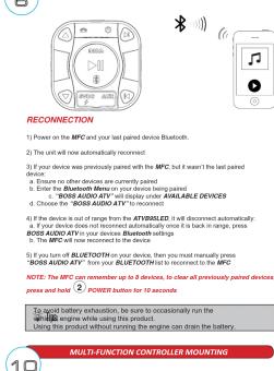
RECONNECTION 1) Power on the MPC and your last paired device Bluetooth. 2) The unit will now automatically recommend: 3) If your device was previously paired with the MPC, but I wasn't the last paired device. 4. Ensure no other devices are currently paired 5. Enter for Bluetooth device to be used in being paired 6. "BIOSA AUDIO" will display only AVAILABLE DEVICES 7. Choose "BIOSA AUDIO" to be recommended: 8) If the device is out of range from the .IF: AVIIRV(ILED) will be advertised accordingly. 9. If your device does not recommend automatically once to be back in range, press BIOSA AUDIO's your device will have growth settings 10. The MPC will now recommend to the device. 11) If you turn at BLUETOOTH on your device, then you must normalize press "BIOSA AUDIO" to be replaced by the MPC. NOTE: The MPC can remember up to 8 devices, to clear all previously paired devices, press and hold 2 POWER buttons for 10 seconds. To avoid battery exhaustion, we sure to occasionally run the MPC engine while using this product. Using this product without running the engine can drain the battery. MULTI-FUNCTION CONTROLLER MOUNTING

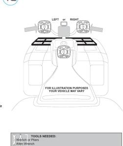
LEFT or RIGHT FOR ILLUSTRATION PURPOSES YOUR VEHICLE MAY VARY TOOLS NEEDED: Wrench or Flies A/John Wrench

Scanned text of safety guidelines for installation precautions, including safety recommendations and optional requirements.

MULTIFUNCTION CONTROLLER BLUETOOTH OPERATION 1) Press the 4 PLAYTAUSE once to start playing music or press the PLAY button from your devices touch screen 2) To skip range or advance, press the 3 NEXT TRACK button 3) To select the previous ramp, press the 5 PREVIOUS TRACK button VOLUME CONTROL 4) To raise the volume press the 6 VOL UP button 5) To lower the volume press the 7 VOL DOWN button Maintenance your device Bluetooth volume is set at 100% level &N=8000000000000000000000000000000000000000000000000000000000000000000000000

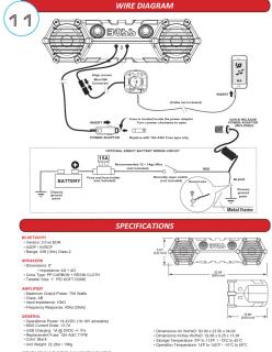
11 WIRE DIAGRAM SPECIFICATIONS SPECTIONS: - Motor Control: 200A - Motor Power: 300A - Motor Currents: 100A - Motor Voltage: 50A - Motor Currents: 100A - Motor Power: 300A - Motor Currents: 100A - Motor Power: 300A - Motor Currents: 100A - Motor Power: 300A - Motor Currents: 100A - Motor Power: 300A - Motor Currents: 100A - Motor Power: 300A - Motor Currents: 100A - Motorcycle Control - Motor Control: 200A - Motor Power: 300A - Motor Currents: 100A - Motor Power: 300A - Motor Currents: 100A - Motor Power: 300A - Motor Currents: 100A - Motorcycle Control - Motor Control: 200A - Motor Power: 300A - Motor Currents: 10O - Motor Power: 300A - Motor Currents: 10O - Motor Power: 300A - Motor Currents: 10O - Motorcycle Control - Motor Control: 200A - Motor Power: 300A - Motor Currents: 10O - Motor Power: 300A - Motor Currents: 10O - Motorcycle Control - Motor Control: 200A - Motor Power: 300A - Motor Currents: 10O - Motor Power: 300A - Motor Currents: 10O - Motorcycle Control Motor Control: 200A Motor Power: 300A Motor Currents: 10O - Motor Power: 300A - Motor Currents: 10O - Motor Power: 300A - Motor Currents: 10O - Motorcycle Control Motor Control: 200A Motor Power: 300A Motor Currents: 10O - Motor Power: 300A - Motor Currents: 10O - Motor Power: 30O - Motor Currents: 10O - Motorcycle Control Motor Control: 200A Motor Power: 300A Motor Currents: 10O - Motor Power: 300A - Motor Currents: 10O - Motor Power: 300A

GETTING STARTED GETTING TO KNOW YOUR ATVB9SLED MULTIFUNCTION CONTROLLER (MFC) 1 USB CHARGING 3.5mm AUX-IN ON/OFF 1 MFC - MULTIFUNCTION CONTROLLER 2 LED LIGHTBAR ON/OFF 3 POWER ON/OFF - Press and hold for 3 seconds 4 NEXT TRACK 5 PLAY/PAUSE 6 BLUETOOTH PAIRING INDICATOR - BLUE COLOR 7 PREVIOUS TRACK 8 VOL DOWN 9 VOL UP

AUX-INPUT YOUR DEVICE ATV8BLED can play audio from any device that has a 3.5mm headphone/voice audio jack LIFT TO OPEN 4 MULTIFUNCTION CONTROLLER-AUX-IN OPERATION 1) Power on the ATV8BLED pressing and holding down the 2 POWER button for 3 seconds. 2) Dispersed or 3 sensors AUX-IN cable located on the front of the MPC's your devices headphone jack, the LED will Bluetooth RD color when in AUXIN mode 4) Pulse the wire back to the MPC secure your device in a safe position VOLUME CONTROL 5) To raise the volume press the 6 VLD LIP button 6) To lower the volume press the 7 VLD DOWN button 7) To MOTE the volume press the 8 PLAYPA/PU button

Make sure your device headphone volume is set at 100% level Like us on Facebook! BE THE FIRST TO SEE NEW PRODUCTS! BOSS AUDIO SYSTEMS SHARE YOUR BOSS AUDIO SYSTEM PHOTOS! WATCH FOR CONTEST GIVEWAYS AND WIN PRIZES!

Manual assistant
Powered by Anthropic
Waiting for your message
Product information

Brand : BOSS

Model : ATVB95LED

Category : Audio System