
DMCO-33 - Audio/video switch Crestron - Free user manual and instructions
Find the device manual for free DMCO-33 Crestron in PDF.


| Product Type | Audio/Video Switch |
| Model | DMCO-33 |
| Brand | Crestron |
| Dimensions (H x W x D) | 1.7 x 17.2 x 10.8 in (43 x 437 x 274 mm) |
| Weight | 6.6 lb (3.0 kg) |
| Power Supply | 100-240 VAC, 50/60 Hz, internal |
| Power Consumption | 45 W typical |
| Video Inputs | 3x HDMI, 3x DisplayPort |
| Video Outputs | 3x HDMI, 1x HDBT |
| Max Resolution | 4K@60Hz 4:4:4 |
| Audio Support | Embedded audio, Dolby TrueHD, DTS-HD |
| Control Interface | Ethernet, RS-232, IR, CEC |
| Rack Mountable | Yes, 1U |
| Operating Temperature | 32°F to 104°F (0°C to 40°C) |
| Storage Temperature | -4°F to 140°F (-20°C to 60°C) |
| Humidity | 10% to 90% (non-condensing) |
| Maintenance | Wipe with dry cloth; avoid liquids |
| Safety | CE, FCC, UL Listed |
| Spare Parts | Replacement power supply, rack ears, cables |
| Repairability | Modular design; contact Crestron for service |
Frequently Asked Questions - DMCO-33 Crestron
User questions about DMCO-33 Crestron
0 question about this device. Answer the ones you know or ask your own.
Ask a new question about this device
Download the instructions for your Audio/video switch in PDF format for free! Find your manual DMCO-33 - Crestron and take your electronic device back in hand. On this page are published all the documents necessary for the use of your device. DMCO-33 by Crestron.
USER MANUAL DMCO-33 Crestron
Crestron DM-MD8X8/16X16/32X32
DigitalMedia™ Switchers
Operations Guide
Important Safety Instructions
- Read these instructions.
- Keep these instructions.
- Heed all warnings.
- Follow all instructions.
• Do not use this apparatus near water.
- Clean only with dry cloth.
- Do not block any ventilation openings. Install in accordance with the manufacturer's instructions.
- Do not install near any heat sources such as radiators, heat registers, stoves, or other apparatus (including amplifiers) that produce heat.
- Do not defeat the safety purpose of the polarized or grounding-type plug. A polarized plug has two blades with one wider than the other. A grounding-type plug has two blades and a third grounding prong. The wide blade or the third prong are provided for your safety. If the provided plug does not fit into your outlet, consult an electrician for replacement of the obsolete outlet.
- Protect the power cord from being walked on or pinched particularly at plugs, convenience receptacles, and the point where they exit from the apparatus.
- Only use attachments/accessories specified by the manufacturer.
- Use only with the cart, stand, tripod, bracket or table specified by the manufacturer or sold with the apparatus. When a cart is used, use caution when moving the cart/apparatus combination to avoid injury from tip-over.

- Unplug this apparatus during lightning storms or when unused for long periods of time.
- Refer all servicing to qualified service personnel. Servicing is required when the apparatus has been damaged in any way, such as power-supply cord or plug is damaged, liquid has been spilled or objects have fallen into the apparatus, the apparatus has been exposed to rain or moisture, does not operate normally, or has been dropped.
- Disconnect power prior to connecting or disconnecting equipment.
• Do not install in direct sunlight.
- The apparatus must be installed in a way that the power cord can be removed either from the wall outlet or from the device itself in order to disconnect the mains power.
• Prevent foreign objects from entering the device.
WARNING:
TO REDUCE THE RISK OF FIRE OR ELECTRIC SHOCK, DO NOT EXPOSE THIS APPARATUS TO RAIN OR MOISTURE. THE APPARATUS SHALL NOT BE EXPOSED TO DRIPPING OR SPLASHING. OBJECTS FILLED WITH LIQUIDS, SUCH AS VASES, SHOULD NOT BE PLACED ON THE APPARATUS.
WARNING:
TO PREVENT ELECTRIC SHOCK, DO NOT REMOVE COVER. THERE ARE NO USER SERVICEABLE PARTS INSIDE. ONLY QUALIFIED SERVICE PERSONNEL SHOULD PERFORM SERVICE.

The lightning flash with arrowhead symbol, within an equilateral triangle, is intended to alert the user to the presence of uninsulated “dangerous voltage” within the product's enclosure that may be of sufficient magnitude to constitute a risk of electric shock to persons.

The exclamation point within an equilateral triangle is intended to alert the user to the presence of important operating and maintenance (servicing) instructions in the literature accompanying the appliance.
WARNING:
THIS IS AN APPARATUS WITH CLASS I CONSTRUCTION. IT SHALL BE CONNECTED TO AN ELECTRICAL OUTLET WITH AN EARTHING GROUND TERMINAL.
IMPORTANT:
This device can be used with Class 2 output wiring.
Regulatory Compliance
As of the date of manufacture, the DM-MD8X8, DM-MD16X16, and DM-MD32X32 have been tested and found to comply with specifications for CE marking.
CE
Federal Communications Commission (FCC) Compliance Statement
This device complies with part 15 of the FCC Rules. Operation is subject to the following conditions:
(1) This device may not cause harmful interference and (2) this device must accept any interference received, including interference that may cause undesired operation.
CAUTION: Changes or modifications not expressly approved by the manufacturer responsible for compliance could void the user's authority to operate the equipment.
NOTE: This equipment has been tested and found to comply with the limits for a Class B digital device, pursuant to part 15 of the FCC Rules. These limits are designed to provide reasonable protection against harmful interference in a residential installation. This equipment generates, uses and can radiate radio frequency energy and, if not installed and used in accordance with the instructions, may cause harmful interference to radio communications. However, there is no guarantee that interference will not occur in a particular installation. If this equipment does cause harmful interference to radio or television reception, which can be determined by turning the equipment off and on, the user is encouraged to try to correct the interference by one or more of the following measures:
• Reorient or relocate the receiving antenna
- Increase the separation between the equipment and receiver
- Connect the equipment into an outlet on a circuit different from that to which the receiver is connected
- Consult the dealer or an experienced radio/TV technician for help
Industry Canada (IC) Compliance Statement
CAN ICES-3(B)/NMB-3(B)
This device includes an aggregation of separate independent works that are each generally copyrighted by Crestron Electronics, Inc., with all rights reserved. One of those independent works, Linux Bridge Project, is copyrighted under the GNU GENERAL PUBLIC LICENSE, Version2, reproduced in "12BGNU General Public License" on page 180, where the corresponding source code is available at: ftp://ftp.crestron.com/gpl.
The specific patents that cover Crestron products are listed at patents.crestron.com.
Manufactured under license under U.S. Patent Nos.: 5,956,674; 5,974,380; 6,226,616; 6,487,535; 7,212,872; 7,333,929; 7,392,195; 7,272,567 & other U.S. and worldwide patents issued & pending. DTS-HD, the Symbol, & DTS-HD and the Symbol together are registered trademarks of DTS, Inc. Product includes software. © DTS, Inc. All Rights Reserved.
Manufactured under license from Dolby Laboratories. Dolby and the double-D symbol are trademarks of Dolby Laboratories.
Crestron, the Crestron logo, CresFiber, Crestron Studio, Crestron Toolbox, DigitalMedia, DM, DMNet, and QuickSwitch HD are either trademarks or registered trademarks of Crestron Electronics, Inc. in the United States and/or other countries. Blu-ray Disc is either a trademark or registered trademark of the Blu-ray Disc Association (BDA) in the United States and/or other countries. Dolby and Dolby Digital are either trademarks or registered trademarks of Dolby Laboratories in the United States and/or other countries. DTS and DTS-HD Master Audio are either trademarks or registered trademarks of DTS, Inc. in the United States and/or other countries. HDMI and the HDMI Logo are either trademarks or registered trademarks of HDMI Licensing, LLC in the United States and/or other countries. Other trademarks, registered trademarks, and trade names may be used in this document to refer to either the entities claiming the marks and names or their products. Crestron disclaims any proprietary interest in the marks and names of others. Crestron is not responsible for errors in typography or photography.
This document was written by the Technical Publications department at Crestron.
©2014 Crestron Electronics, Inc.
Contents
DigitalMedia Switchers: DM-MD8X8/16X16/32X32 1
Introduction ....1
Features and Functions....1
Applications....6
Internal Block Diagrams....7
Specifications 9
Physical Description....15
Setup 28
DigitalMedia Wiring 28
HDCP Signal Path 30
Ethernet Setup 32
Identity Code 32
Installation 33
Hardware Hookup 34
Configuration....41
Inputs 42
Outputs 43
Network....44
Control....49
Message Log....53
Commission System....54
Uploading and Upgrading....61
Establishing Communication....61
Programs and Firmware 62
Program Checks 62
DM Tool....63
Operation 64
Operating Modes 64
Route Mode 64
View Mode....65
Info Mode 66
Problem Solving 67
Troubleshooting....67
Check Network Wiring....68
Reference Documents....69
Further Inquiries....69
Future Updates 69
Appendix A: Hardware Hookup for DM Cards....70
Input Cards 70
Output Connections 82
Appendix B: Input Card Configuration 85
DMC-CAT 86
DMC-CAT-DSP 94
DMC-DVI 102
DMC-F 110
DMC-F-DSP....116
DMC-HD....122
DMC-HD-DSP 130
DMC-SDI 138
DMC-VID4 142
DMC-VID-BNC 149
DMC-VID-RCA-A....156
DMC-VID-RCA-D....163
Appendix C: Output Configuration 170
Glossary 175
Return and Warranty Policies....179
Merchandise Returns / Repair Service 179
Crestron Limited Warranty....179
GNU General Public License 180
DigitalMedia Switchers: DM-MD8X8/16X16/32X32
Introduction
Crestron ^® DigitalMedia ^™ switchers provide the foundation for a complete DigitalMedia system, delivering a true high-definition multi-room AV signal routing solution that is flexible and installer-friendly. The DM-MD8X8, DM-MD16X16, and DM-MD32X32 afford low-latency switching and pure, lossless distribution of HDMI ^® and other signals to support the latest Blu-ray Disc ^® players, HDTV receivers, digital media servers, computers, and other AV devices.
Features and Functions
- Three Models: DM-MD8X8 (eight inputs, eight outputs), DM-MD16X16 (16 inputs, 16 outputs), and DM-MD32X32 (32 inputs, 32 outputs)
- Distributes uncompressed digital video and audio over twisted-pair wire or fiber
• Supports HDMI with Deep Color and 7.1 channel HD lossless audio
• Supports video resolutions up to WUXGA 1920x1200 and HD 1080p60 - Allows cable length to 450 feet (137 m) using DigitalMedia cable, 1000 feet (300 m) using CresFiber ^®
- Supports up to eight (DM-MD8X8), 16 (DM-MD16X16), or 32 (DM-MD32X32) DM ^® receivers and room controllers with easy expansion for more outputs
- Configurable inputs support a complete range of digital and analog signal types
• Detects and displays detailed video and audio input information - QuickSwitch HD ^ technology achieves low-latency HDMI switching
• Manages HDCP digital rights management for every device
• Performs automatic AV signal format management via EDID
• Enables device control via CEC
• Distributes USB HID mouse and keyboard signals - Allows full audio and USB breakaway switching
• Integrates with analog audio distribution systems - Enables simultaneous output of stereo and surround sound audio
- Includes integrated Ethernet switch with Gigabit LAN port
(Continued on following page)
Features and Functions
(Continued)
- Includes built-in power distribution for DM transmitters, repeaters, and room controllers
- Provides easy setup and diagnostics tools via front panel or software
- 19-inch rack-mountable (DM-MD8X8: 4-space, DM-MD16X16: 7-space, DM-MD32X32: 14-space)
DM switchers are field-configurable to handle up to 32 AV sources of virtually any type. The outputs of the DM-MD32X32 are field-configurable to provide up to 32 DM room outputs and/or HDMI outputs in a single chassis, with expansion capability possible for up to 160 outputs using multiple chassis. The outputs of the DM-MD16X16 are factory-configurable to provide up to 16 DM room outputs and/or HDMI outputs in a single chassis, with expansion capability possible for up to 80 outputs using multiple chassis. The outputs of the DM-MD8X8 are field-configurable to provide up to eight DM room outputs and/or HDMI outputs in a single chassis, with expansion capability possible for up to 40 outputs using multiple DM-MD8X8 chassis.
A full selection of DM switcher input cards, DM transmitters, DM receivers, and DM room controllers provides extensive connectivity throughout the home or office, supporting a complete range of analog and digital signal types — all through one switcher. User-friendly setup and troubleshooting tools are provided through the front panel, or via Crestron Toolbox™ software, to simplify setup.
DigitalMedia switchers are part of a High Definition Audio-Video distribution system that allows virtually any mix of AV sources to be distributed throughout the home from a centralized rack location using DigitalMedia.
DigitalMedia
Creating a professional HD AV distribution system means handling the challenges that come with HDMI. HDMI is the new standard for interfacing high-definition AV equipment, but despite its many benefits, it was not developed with multi-room distribution in mind. Crestron has developed DigitalMedia, the first complete HD AV distribution system that allows virtually any mix of HD AV sources to be distributed throughout the home from a centralized rack location.
DigitalMedia distributes uncompressed digital video and audio signals over a choice of shielded twisted-pair copper wire or multi-mode fiber. DigitalMedia manages all of the different signals and devices, matching each source's output to the capabilities of the selected display(s) without using scaling or compression. Every signal is preserved in its native video resolution and audio format, ensuring a pure, lossless signal path throughout.
Integrated Ethernet and USB HID distribution allows computers and media servers, to be installed out-of-sight and accessed from anywhere in the house. Crestron control is also built-in for controlling the displays and other room devices without additional wiring.
Modular Architecture
DM switchers feature a modular architecture with eight (DM-MD8X8), 16 (DM-MD16X16), or 32 (DM-MD32X32) input card slots and two output card slots with two, four, six, or eight outputs. Each input card slot on a DM switcher is
field-installable, allowing for easy and flexible system configuration with the ability to make changes to the system as needs change.
A wide selection of DM input cards are offered to support a complete range of digital and analog AV signal types. Depending on the switcher, up to eight output cards may be installed to feed up to eight (DM-MD8X8), 16 (DM-MD16X16), or 32 (DM-MD32X32) DM Receivers/Room Controllers using either DigitalMedia (DM) Cable or CresFiber. DigitalMedia allows for cable lengths up to 450 feet (137 m) using DM cable, or 1000 feet (300 m) using CresFiber. HDMI outputs are also available for direct connection to centralized audio processors and video monitors.
Output Expansion
An HDMI loop back output is provided on every input card to allow the inputs of up to five DM switchers to be daisy-chained, enabling the configuration of very large distribution systems with many DM and HDMI outputs.
Versatile Audio Routing
HDMI is the key to handling all the latest 7.1 surround sound formats like Dolby® TrueHD and DTS-HD Master Audio™. Great for your high-end home theater, but how do you share that same source with other audio zones in the house?
DigitalMedia allows for the simultaneous distribution of multi-channel surround sound (i.e., Dolby TrueHD and DTS-HD Master Audio) and two-channel stereo signals from the same HDMI source. Equipped with a DMC-HD-DSP, DMC-F-DSP, or DMC-CAT-DSP input card (all sold separately), the DM switcher employs onboard DSP processing to derive a stereo down-mix from the original multi-channel signal. Both signals can be routed separately or simultaneously from any of the switcher's DM outputs, allowing either signal to be selected for output at each DM receiver location.
The switcher also converts the digital stereo signal to analog to enable sharing with every other room in the house via an AAE, CNX-PAD8A (both sold separately), or other multi-room audio distribution system. DM switchers also allow surround sound processors and amplifiers to be located centrally instead of at the display location using optional local HDMI outputs.
Computer Compatibility
Besides handling every available HDTV format supported by HDMI, DigitalMedia also supports the distribution of DVI, DisplayPort multimode*, and RGB computer signals, and is fully compatible with DVI computer monitors up to 1920 x 1200 WUXGA.
Built-in Ethernet Switch
In addition to transporting digital video and audio, DigitalMedia can also extend 10/100 Ethernet out to each display and source device via DM room controllers and select DM transmitters, providing high-speed connectivity for any room device that requires a LAN connection. Its Gigabit Ethernet connection to the external LAN helps maximize bandwidth for each network port. Ethernet is also utilized internally by the Crestron control bus to manage all of the DM devices in the system and provide display control in each room.
USB HID Switch
DigitalMedia lets you centralize all HD sources – not just television receivers and DVD changers, but also media servers and computers. Built-in USB HID (Human Interface Device) signal routing allows USB HID compatible keyboards and mice to be connected at a remote display location, conference table or presentation lectern, extending their signals through to the centralized equipment via USB HID ports provided on select switcher input cards.
EDID Format Management
Using HDMI provides a variety of video and audio formats to keep track of, and chances are not every device in a system supports all of the same formats. In a typical one-room system, HDMI attempts to resolve this confusion using EDID (Extended Display Identification Data). When two HDMI devices are connected together, the receiving device (a display or surround sound processor) uses EDID to announce its format capabilities to the source device (a TV tuner or video player), which in turn configures itself to output the most effective format that both devices can support.
However, serious conflicts arise in a facility filled with different displays and audio systems. For instance, the Blu-ray Disc player that is feeding a 1080p projector in the theater may restrict itself to a lower resolution, or even shut off completely, if someone decides to view the same signal on the 20" TV in the kitchen. And, instead of listening to a 7.1 Dolby TrueHD format supported by a high-end theater sound system, the listening experience may be limited to Dolby 5.1, or even stereo sound.
DM switchers use EDID to prevent such conflicts, assessing the formats supported by each system device, and then allowing the installer to assign compatible devices in logical arrangements. Conflicting combinations can be prohibited so only the optimum signal formats get delivered to each display and audio system in the house. All DigitalMedia wiring is also tested for integrity and bandwidth capability, optimizing system operation by instructing sources to output only resolutions and formats that the wiring can reliably handle.
QuickSwitch HD Technology
Crestron QuickSwitch HD technology minimizes the switching latency that plagues typical HDMI switchers. As the move to digital takes hold, more and more movie studios and television service providers are using HDCP (High-bandwidth Digital Content Protection) to protect their DVDs, Blu-ray Discs, and broadcast signals against unauthorized copying. Viewing the HDCP encrypted content in its full high-definition format requires a source device to “authenticate” each display and signal processor in the system through an HDMI connection before delivering an output signal. Normally the authentication process occurs every time any HDMI signal is switched, causing a complete loss of signal for up to 15 seconds whenever a new source or display is selected anywhere in the system.
QuickSwitch HD technology achieves very fast switching of HDMI signals by maintaining a constant HDCP connection with each HDMI device in the system, eliminating the need to re-authenticate each time a different source is selected.
HDCP Key Management
Another aspect to HDCP is its use of “keys” to manage the handshaking that occurs between any two devices. Every HDMI source device has a limit to how many downstream devices it can support, determined by the number of HDCP keys it has available. Rarely is that limit advertised or specified by the manufacturer or service provider, so connect too many displays or processors and the source will simply stop outputting a signal without warning.
To prevent such surprises, DM switchers test the HDCP limits of each HDMI source, allowing the installer to configure the system around any limitations, or substitute a different component.
CEC Embedded Device Control
The primary objective of every Crestron system is to enable precisely the control desired for a seamless user experience. DigitalMedia provides an alternative to conventional IR and RS-232 device control by harnessing the CEC (Consumer Electronics Control) signal embedded in HDMI. Through its connection to the control system, the DM switcher provides a gateway for controlling many devices right through their HDMI connections, potentially eliminating the need for any dedicated control wires or IR probes. Through proper CEC signal management, DigitalMedia allows you to take control of each device as you like.
Easy Setup
Via the front panel or using Crestron Toolbox™ software, every step of the DM switcher's setup process is designed to be quick and easy, configuring inputs and outputs automatically while letting the installer make intelligent design decisions along the way. The switcher tests and measures the length of each DM cable, automatically making the appropriate calibrations for optimal signal transmission to every room. With DigitalMedia, an entire switcher system can be commissioned in as little as 15 minutes.
Applications
The following diagram shows a DM-MD8X8 in a lecture hall application.
DM-MD8X8 in a Lecture Hall Application

flowchart
graph TD
    A["7J SURROUND SOUND SYSTEM"] -->|HDMI| B["ROOM 1 Through 8"]
    C["HDTV DISPLAY"] -->|USB| B
    D["KEYBOARD & MOUSE"] -->|USB| B
    B -->|DigitalMedia Cable| E["ROOM 1 Through 8"]
    E --> F["DM-RHC-100 Room Solution Box"]
    F --> G["DigitalMedia Cable"]
    G --> H["DigitalMedia Cable"]
    H --> I["COMPUTER"]
    I --> J["Computer"]
    K["DRAM REPEATER if necessary"] --> L["DigitalMedia Cable"]
    L --> M["DM-MD8X8 SWITCHER"]
    N["LAN"] --> O["DigitalMedia Cable"]
    P["Audio SERVER"] --> Q["DigitalMedia Cable"]
    R["CONTROL SYSTEM"] --> S["DigitalMedia Cable"]
    T["Blu-Ray"] --> U["DigitalMedia Cable"]
    V["Video"] --> W["DigitalMedia Cable"]
    X["HDMI/DVI"] --> Y["DigitalMedia Cable"]
Internal Block Diagrams
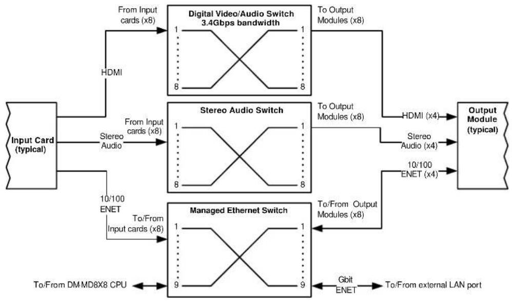
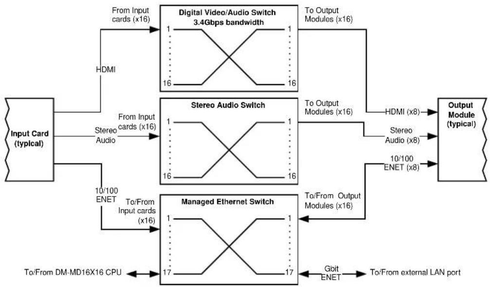
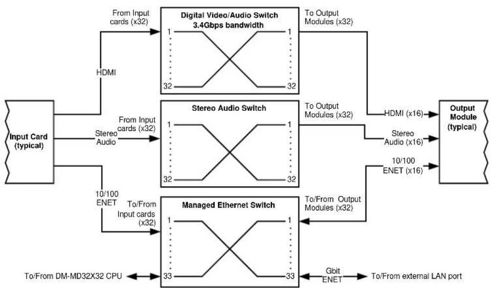
The following diagrams represent the switching abilities of the DM switchers.
Internal Block Diagram of the DM-MD8X8
DM-MD8X8 Internal Block Diagram
flowchart
graph TD
    A["Input Card (typical)"] -->|HDMI| B["Digital Video/Audio Switch 3.4Gbps bandwidth"]
    A -->|Stereo Audio| C["Stereo Audio Switch"]
    A -->|10/100 ENET| D["Managed Ethernet Switch"]
    B -->|To Output Modules (x8)| E["Output Module (typical)"]
    C -->|To Output Modules (x8)| E
    D -->|To/From Input cards (x8)| F["To/From DMMD8X8 CPU"]
    D -->|To/From Output Modules (x8)| G["Gbit ENET"] --> H["To/From external LAN port"]
    B -->|To Output Modules (x8)| I["HDMI (x4)"]
    C -->|To Output Modules (x8)| J["Stereo Audio (x4)"]
    D -->|To/From Output Modules (x8)| K["To/From External LAN port"]
Internal Block Diagram of the DM-MD16X16
DM-MD16X16 Internal Block Diagram
flowchart
graph TD
    A["Input Card (typical)"] -->|From Input cards (x16)| B["Digital Video/Audio Switch 3.4Gbps bandwidth"]
    A -->|HDMI| B
    B -->|To Output Modules (x16)| C["Output Module (typical)"]
    A -->|Stereo Audio| D["Stereo Audio Switch"]
    A -->|10/100 ENET| E["Managed Ethernet Switch"]
    D -->|To Output Modules (x16)| F["HDMI (x8)"]
    D -->|Stereo Audio (x8)| G["10/100 ENET (x8)"]
    E -->|To/From Output Modules (x16)| H["Gbit ENET"]
    E -->|To/From Input cards (x16)| I["To/From DM-MD16X16 CPU"]
    E -->|To/From external LAN port| J["To/From external LAN port"]
Internal Block Diagram of the DM-MD32X32
DM-MD32X32 Internal Block Diagram
flowchart
graph TD
    A["Input Card (typical)"] -->|From Input cards (x32)| B["Digital Video/Audio Switch 3.4Gbps bandwidth"]
    A -->|Stereo Audio| C["Stereo Audio Switch"]
    A -->|10/100 ENET| D["Managed Ethernet Switch"]
    B -->|To Output Modules (x32)| E["Output Module (typical)"]
    B -->|HDMI| F["HDMI"]
    C -->|To Output Modules (x32)| G["HDMI"]
    C -->|Stereo Audio (x16)| H["Stereo Audio"]
    C -->|10/100 ENET (x16)| I["ENET"]
    D -->|To/From DM-MD32X32 CPU| J["To/From DM-MD32X32 CPU"]
    D -->|Gbit ENET| K["To/From external LAN port"]
Specifications
Specifications for DM switchers are listed in the following table.
DM Switcher Specifications
| SPECIFICATION DETAILS | |
| VideoSwitcher | DM-MD8X8:8x8 digital matrix, modular input/output cards,Crestron QuickSwitch HDDM-MD16X16:16x16 digital matrix, modular input/outputcards, Crestron QuickSwitch HDDM-MD32X32:32x32 digital matrix, modular input/outputcards, Crestron QuickSwitch HD |
| Input Signal Types | Configurable via modular plug-in cardssupporting HDMI, DisplayPort Multimode ^1 ,DVI, SDI, RGB, component (YP _b Pr), S-video(Y/C), composite video, DM CAT, and DMfiber |
| Output Signal Types | Configurable via plug-in cards (factory-installed on DM-MD16X16) supporting DMCAT, DM fiber, and HDMI (All input cards alsoinclude HDMI loop back outputs) |
| Formats(determined by input cards) | HDMI with Deep Color, DVI, HDCP v.1.2content protection support, SD-SDI, HD-SDI,3G-SDI, RGBHV up to UXGA/WUXGA, HDTVup to 1080p60, NTSC or PAL |
| Input ResolutionsHDMI/DVI, Progressive | 640x480@60Hz, 720x480@60Hz (480p),720x576@50Hz (576p), 800x600@60Hz,848x480@60Hz, 852x480@60Hz,854x480@60Hz, 1024x768@60Hz,1024x852@60Hz, 1024x1024@60Hz,1280x720@50Hz (720p50), 1280x720@60Hz(720p60), 1280x768@60Hz,1280x800@60Hz, 1280x960@60Hz,1280x1024@60Hz, 1360x768@60Hz,1365x1024@60Hz, 1366x768@60Hz,1400x1050@60Hz, 1440x900@60Hz,1600x900@60Hz, 1600x1200@60Hz,1680x1050@60Hz, 1920x1080@24Hz(1080p24), 1920x1080@25Hz (1080p25),1920x1080@50Hz (1080p50),1920x1080@60Hz (1080p60),1920x1200@60Hz, 2048x1080@24Hz,2048x1152@60Hz, plus any other resolutionallowed by HDMI up to 165MHz pixel clock |
| Video (continued)Input ResolutionsHDMI/DVI, Interlaced | 720x480@30Hz (480i), 720x576@25Hz(576i), 1920x1080@25Hz (1080i25),1920x1080@30Hz (1080i30), plus any otherresolution allowed by HDMI up to 165MHzpixel clock |
| RGB | 640x480@60Hz, 720x480@60Hz (480p),720x576@50Hz (576p), 800x600@60Hz,848x480@60Hz, 1024x768@60Hz,1280x720@50Hz (720p50), 1280x720@60Hz(720p60), 1280x768@60Hz,1280x800@60Hz, 1280x960@60Hz,1280x1024@60Hz, 1360x768@60Hz,1366x768@60Hz, 1400x1050@60Hz,1440x900@60Hz, 1600x1200@60Hz,1680x1050@60Hz, 1920x1080@24Hz(1080p24), 1920x1080@50Hz (1080p50),1920x1080@60Hz (1080p60),1920x1200@60Hz, 2048x1080@24Hz,2048x1152@60Hz |
| Component | 480i, 576i, 480p, 576p, 720p50, 720p60,1080i25 (1125 lines), 1080i30, 1080p30,1080p50 (1125 lines), 1080p60 |
| Composite and S-video | 480i, 576i |
| SDI | SMPTE 425M (3G-SDI) 4:2:2 Colorspace:1920x1080@50Hz (1080p50),1920x1080@60Hz (1080p60);SMPTE 425M (3G-SDI) 4:4:4 Colorspace:1280x720@24Hz (720p24), 1280x720@25Hz(720p25), 1280x720@50Hz (720p50),1280x720@60Hz (720p60),1920x1080@24Hz (1080p24),1920x1080@25Hz (1080p25),1920x1080@30Hz (1080p30),1920x1080@50Hz (1080i50 or 1080sF25),1920x1080@60Hz (1080i60 or 1080sF30);SMPTE 260M (HD-SDI): 1920x1035@60Hz(1035i60);SMPTE 295M (HD-SDI): 1920x1080@50Hz(1080i50);SMPTE 274M (HD-SDI): 1920x1080@24Hz(1080p24), 1920x1080@24Hz (1080sF24),1920x1080@25Hz (1080p25),1920x1080@30Hz (1080p30),1920x1080@50Hz (1080i50 or 1080sF25),1920x1080@60Hz (1080i6o or 1080sF30);SMPTE 296M (HD-SDI): 1280x720@24Hz(720p24), 1280x720@25Hz (720p25),1280x720@30Hz (720p30), 1280x720@50Hz(720p50), 1280x720@60Hz (720p60);SMPTE 259M-C (SD-SDI): 720x480@59.94(NTSC), 720x576@50i (PAL) |
| Output ResolutionsBackplane Data Rate | Matched to inputs12.5 Gbps |
| AudioSwitcher | DM-MD8X8:8x8 digital multi-channel audio-follow-video matrix switching, plus independent 8x8 stereo matrix for audio breakawayDM-MD16X16:16x16 digital multi-channel audio-follow-video matrix switching, plus independent 16x16 stereo matrix for audio breakawayDM-MD32X32:32x32 digital multi-channel audio-follow-video matrix switching, plus independent 32x32 stereo matrix for audio breakaway |
| Input Signal Types | Configurable via modular plug-in cards supporting HDMI, DisplayPort Multimode ^1 , SDI, analog (stereo 2-channel), SPDIF, DM CAT, and DM fiber |
| Output Signal Types | Configurable via plug-in cards (factory-installed on DM-MD16X16) supporting DM CAT, DM fiber, HDMI, and analog (stereo 2-channel); (All input cards also include HDMI loop back outputs, and some input cards also include analog stereo loop back audio outputs) |
| FormatsHDMI only | Dolby Digital Plus, Dolby ^ TrueHD, DTS-HD High Res, DTS-HD Master Audio ^TM , up to 8ch PCM |
| HDMI & SPDIF | Dolby Digital ^ , Dolby Digital EX, DTS ^ , DTS-ES, DTS 96/24, 2ch PCM |
| AnalogSDI | Stereo 2-ChannelSMPTE 272M & SMPTE 299M (2 or 8 channel), 2 or 8 channel PCM via HDMI, 2-channel via analog |
| CommunicationsDigitalMedia | DM fiber, DM CAT, DMNet ^ , HDCP management, EDID format management, CEC |
| Ethernet | 10/100/1000BASE-T, auto-switching, auto-negotiating, auto-discovery, full/half duplex, TCP/IP, UDP/IP, CIP, DHCP, RSTP |
| USB | Supports USB HID class devices |
| Ethernet Switch | DM-MD8X8: Provides (1) onboard10/100/1000BASE-T Gigabit Ethernet port,(1) internal 10BASE-T/100BASE-TX Ethernet port for the switcher, and (16) remote10BASE-T/100BASE-TX Ethernet ports via select outboard devicesDM-MD16X16: Provides (1) onboard10/100/1000BASE-T Gigabit Ethernet port,(1) internal 10BASE-T/100BASE-TX Ethernet port for the switcher, and (32) remote10BASE-T/100BASE-TX Ethernet ports via select outboard devicesDM-MD32X32: Provides (1) onboard10/100/1000BASE-T Gigabit Ethernet port,(1) internal 10BASE-T/100BASE-TX Ethernet port for the switcher, and (64) remote10BASE-T/100BASE-TX Ethernet ports via select outboard devices |
| USB Switch | DM-MD8X8: 8x8 matrixDM-MD16X16: 16x16 matrixDM-MD32X32: 32x32matrix |
| Power RequirementsMain Power | DM-MD8X8:300 Watts @ 100-240 Volts AC, 50/60 HzDM-MD16X16:550 Watts @ 100-240 Volts AC, 50/60 HzDM-MD32X32:1100 Watts @ 100-240 Volts AC, 50/60 Hz |
| Available DMNet Power | DM-MD8X8:55 Watts (2.3 Amps @ 24 Volts DC) from internal power supplyDM-MD16X16:110 Watts (4.6 Amps @ 24 Volts DC) from internal power supplyDM-MD32X32:220 Watts (9.2 Amps @ 24 Volts DC) from internal power supply |
| Minimum 2-Series ControlSystem Update File ^2,3 | Version 4.001.1012 or later |
| EnvironmentalTemperatureHumidityHeat Dissipation | 32° to 104° F (0° to 40° C)10% to 90% RH (non-condensing)DM-MD8X8:750 BTU/HrDM-MD16X16:1500 BTU/HrDM-MD32X32:3000 BTU/Hr |
| EnclosureChassisFaceplateMounting | Metal with black finish, vented sides, fan-cooledMetal, black finish with polycarbonate label overlayDM-MD8X8:Freestanding or 4U 19-inch rack-mountable (adhesive feet and rack ears included)DM-MD16X16:Freestanding or 7U 19-inch rack-mountable (adhesive feet and rack ears included)DM-MD32X32:Freestanding or 14U 19-inch rack-mountable (adhesive feet and integrated rack ears) |
| Dimensions (without cards)HeightWidthDepth | DM-MD8X8:6.97 in (177 mm) without feetDM-MD16X16:12.22 in (311 mm) without feetDM-MD32X32:24.44 in (621 mm) without feetDM-MD8X8 and DM-MD16x16:17.28 in (439 mm) without ears19.00 in (483 mm) with earsDM-MD32X32:19.15 in (487 mm)DM-MD8X8 & DM-MD16X16:18.13 in (461 mm)DM-MD32X32:15.72 in (400 mm) |
| Weight (without cards) | DM-MD8X8:20.0 lbs (9.1 kg)DM-MD16X16:28.4 lbs (12.9 kg)DM-MD32X32:64.5 lbs (29.3 kg) |
| Available AccessoriesCRESFIBER | CresFiber Fiber Optic Cable |
| CRESFIBER-CONN-SC50UM-12 | CresFiber Fiber Optic Cable Connector |
| CRESFIBER-DUAL-SC | CresFiber Duplex Fiber Optic Cable Assembly, 50/125, SC |
| CRESFIBER-DUAL-SC-ARMORED | CresFiber Armored Duplex Fiber Optic Cable Assembly, 50/125, SC |
| DM-CBL | DigitalMedia Cable |
| DM-CONN | DigitalMedia Cable Connector |
| DM-DR | DigitalMedia CAT Repeater |
| DMC-CAT | DM CAT Input Card |
| DMC-CAT-DSP | DM CAT Input Card with DSP |
| DMC-DVI | DVI/RGBHV Input Card |
| DMC-F | DM Fiber Input Card |
| DMC-F-DSP | DM Fiber Input Card with DSP |
| DMC-HD | HDMI Input Card |
| DMC-HD-DSP | HDMI Input Card with DSP |
| DMC-SDI | SDI Input Card |
| DMC-VID-BNC | BNC Analog Video Input Card |
| DMC-VID-RCA-A | RCA Analog Video Input Card with Analog Audio |
| DMC-VID-RCA-D | RCA Analog Video Input Card with SPDIF Audio |
| DMC-VID4 | Security Camera Input Card |
| DMCO Series | Output Cards |
-
DisplayPort Multimode connectivity is supported via an HDMI or DVI input port using a suitable adapter or interface cable (not included).
-
The latest software versions can be obtained from the Crestron website. Refer to the NOTE following these footnotes.
-
Crestron 2-Series control systems include the AV2 and PRO2. Consult the latest Crestron Product Catalog for a complete list of 2-Series control systems.
NOTE: Crestron software and any files on the website are for authorized Crestron dealers and Crestron Authorized Independent Programmers (CAIP) only. New users may be required to register to obtain access to certain areas of the site (including the FTP site).
Physical Description
This section provides information on the connections, controls and indicators available on the DM switchers.
DM-MD8X8 Physical View (Front)

DM-MD8X8 Physical View (Rear, Shown with Optional DM Cards)

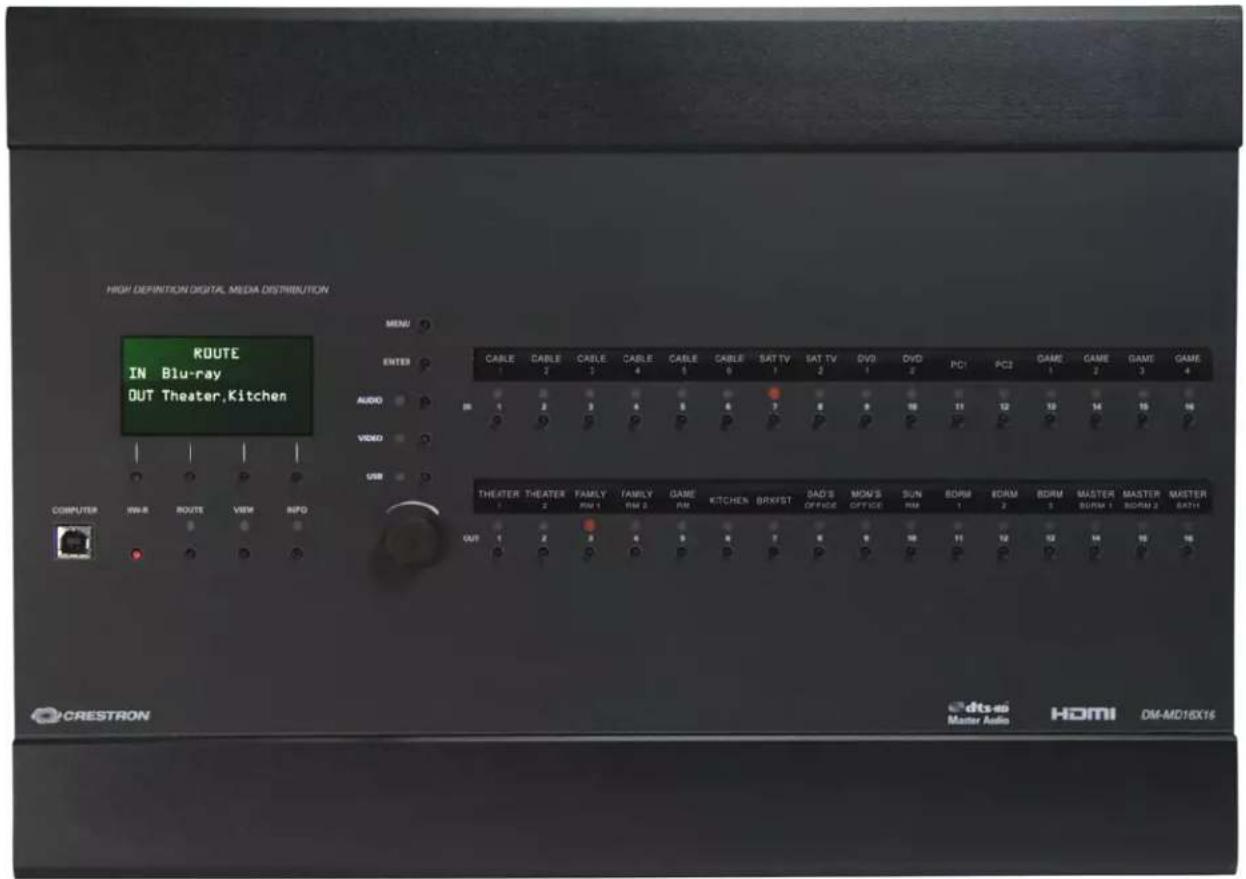
DM-MD16X16 Physical View (Front)
DM-MD16X16 Physical View (Rear, Shown with Optional DM Cards)

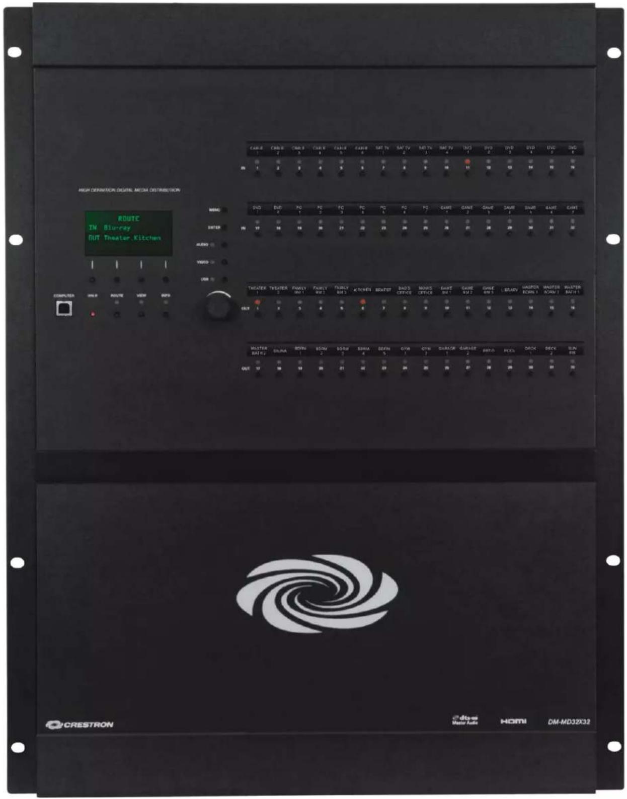
DM-MD32X32 Physical View (Front)
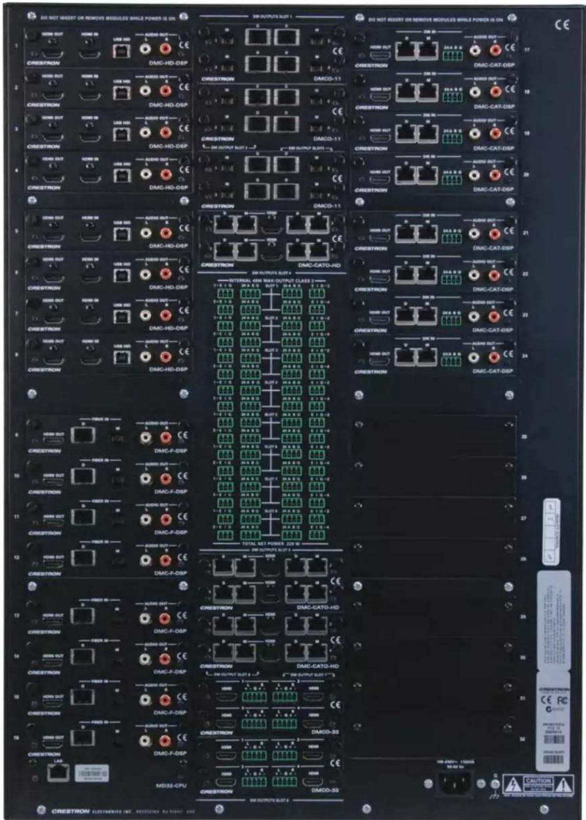
DM-MD32X32 Physical View (Rear, Shown with Optional DM Cards)
DM-MD8X8 & DM-MD16X16 Overall Dimensions
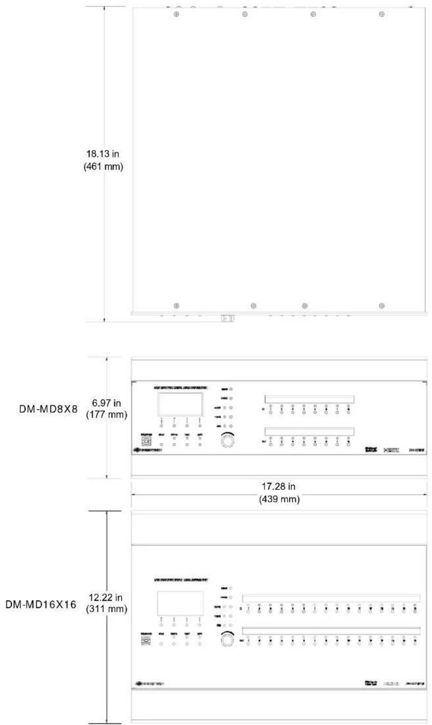
NOTE: Cable connections can extend the overall depth of the DM switcher by approximately two to three inches.
DM-MD32X32 Overall Dimensions

NOTE: Cable connections can extend the overall depth of the DM switcher by approximately two to three inches.
DM-MD8X8 Buttons and Ports

DM-MD16X16 Buttons and Ports
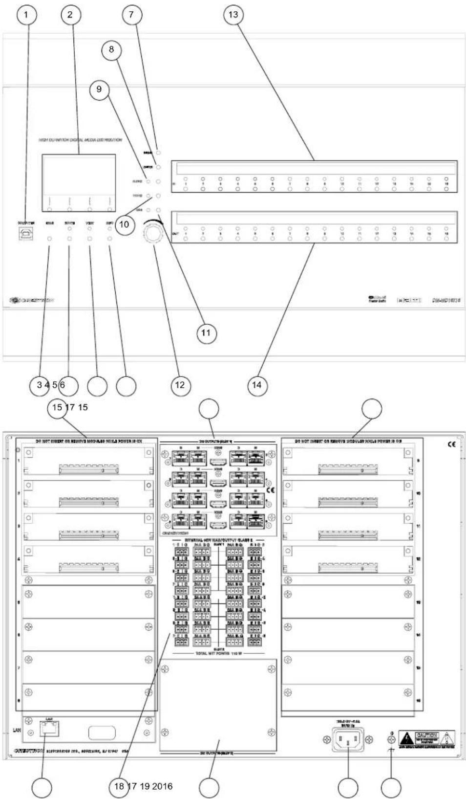
DM-MD32X32 Buttons and Ports

Connectors, Controls & Indicators
| # CONNECTORS1,CONTROLS & INDICATORS | DESCRIPTION | |
1 COMPUTER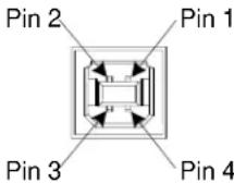 | USB Type B female; USB 1.1 computer console port (6 ft cable included) | |
| PIN DESCRIPTION | ||
| 1 +5 VDC | ||
| 2 Data - | ||
| 3 Data + | ||
| 4 Ground | ||
| 2 LIQUID CRYSTAL DISPLAY & SOFT BUTTONS | LIQUID CRYSTAL DISPLAY (LCD):Green LCD dot matrix, 128 x 64 resolution, adjustable LED backlight;Displays inputs/outputs by name, video & audio signal information, Ethernet configuration and setup menus;SOFT BUTTONS:(4) pushbuttons for activation of LCD driven functions | |
| 3 | HW-R BUTTON | (1) recessed miniature pushbutton for hardware reset, reboots the switcher |
| 4 ROUTE BUTTON & LED | (1) pushbutton and red LED, selects Route mode to allow routing changes | |
| 5 VIEW BUTTON & LED | (1) pushbutton and red LED, selects View mode for viewing current routes | |
| 6 INFO BUTTON & LED | (1) pushbutton and red LED, selects Info mode for viewing AV and device information | |
| 7 | MENU BUTTON | (1) pushbutton, steps menu back one level |
| 8 | ENTER BUTTON | (1) pushbutton, executes highlighted menu or value |
| 9 | AUDIO BUTTON & LED | (1) pushbutton & red LED, selects audio routing view |
| 10 | VIDEO BUTTON & LED | (1) pushbutton & red LED, selects video routing view |
| 11 | USB BUTTON & LED | (1) pushbutton & red LED, selects USB routing view |
| 12 | SELECTION KNOB | (1) Continuous turn rotary encoder, adjusts menu parameters |
| 13 | IN 1-8/16/32 | DM-MD8X8(8) pushbuttons and red LEDs, select input for routingDM-MD16X16(16) pushbuttons and red LEDs, select input for routingDM-MD32X32(32) pushbuttons and red LEDs, select input for routing |
14 OUT 1-8/16/32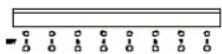 | DM-MD8X8(8) pushbuttons and red LEDs, select output for routingDM-MD16X16(16) pushbuttons and red LEDs, select output for routingDM-MD32X32(32) pushbuttons and red LEDs, select output for routing | |
| 15 CARD SLOTS1-8/16/32 | DM-MD8X8(8) DM switcher input card slots; Accepts (1) DMC-series input card; Input cards are field-installableDM-MD16X16(16) DM switcher input card slots; Accepts (1) DMC-series input card; Input cards are field-installableDM-MD32X32(32) DM switcher input card slots; Accepts (1) DMC-series input card; Input cards are field-installable | |
16 LAN | (1) 8-wire RJ-45 with 2 LED indicators, 10/100/1000BASE-T Ethernet port; Green LED indicates link status, Yellow LED indicates Ethernet activity | |
| 17 DM OUTPUT SLOT21 & 2 / 1-8 | DM-MD8X8 and DM-MD16X16(2) DM switcher output card slots; Each slot accepts (1) 4-channel (DM-MD8X8) or (1) 8-channel (DM-MD16X16) DM output card;DM-MD32X32(8) DM switcher output card slots; Each slot accepts (1) 4-channel DM output card; | |
18 24ABG/EIG 1-4 | DM-MD8X8(8) sets of (1) 4-pin and (1) 3-pin 3.5 mm detachable terminal blocksDM-MD16X16(16) sets of (1) 4-pin and (1) 3-pin 3.5 mm detachable terminal blocksDM-MD32X32(32) sets of (1) 4-pin and (1) 3-pin 3.5 mm detachable terminal blocksThe following applies to all DM switchers:Comprises (8, 16, or 32) DMNet ports with “EIG” power selection ports, each set associated with a corresponding DM output port on the output card in either output slot;Each DMNet port provides power and communications for a DM device connected via DM cable;Each EIG port connects to an external power supply3, or to the internal power source via a jumper, to power the DM device connected to the corresponding DMNet port;Maximum Load: 75 Watts (3.13 Amps @ 24 Volts DC) per port, when connected to external power supply3, otherwise limited to available DMNet power | |
| 19 | 100-240V ~ 4.0A/7.0A50/60 Hz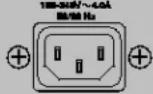 | (1) IEC Socket, main power input; Mates with removable power cord (included)DM-MD8X8: 4.0 Amps Max. Current DrawDM-MD16X16: 7.0 Amps Max. Current DrawDM-MD32X32: 11 Amps Max. Current Draw |
| 20 GROUND | (1) 6-32 screw, chassis ground lug | |
-
Interface connectors for DMNET and EIG ports are provided with the unit.
-
Output cards on DM-MD8X8 and DM-MD32X32 are field-installable (DMC-series). Output cards on DM-MD16X16 (DMCO-series) require factory installation.
-
For external DMNet power, use Crestron CNPWS-75, C2N-SPWS300, or other Cresnet power supply as required.
Setup
DigitalMedia Wiring
Connections between DigitalMedia Switchers and DigitalMedia Room Controllers can be made using a variety of wiring solutions. For optimum performance, Crestron recommends Crestron DigitalMedia cable or CresFiber.
When wiring the DigitalMedia network, consider the following:
- Use Crestron Certified Wire.
• Use Crestron power supplies for Crestron equipment. - Provide sufficient power to the system.
CAUTION: Insufficient power can lead to unpredictable results or damage to the equipment. Please use the Crestron Power Calculator to help calculate how much power is needed for the system (www.crestron.com/calculators).
For information on connecting Ethernet devices in a Crestron system, refer to the latest version of the Crestron e-Control ^® Reference Guide (Doc. 6052), which is available for download from the Crestron website (www.crestron.com/manuals).
DigitalMedia Cable
The Crestron DigitalMedia cable contains two CAT5E cables (one shielded, one unshielded) and one DMNet cable in triamese jackets. Installation of any DigitalMedia device is as simple as connecting DigitalMedia cable from the output of the DigitalMedia switcher to the input of a DigitalMedia device such as a DM-RMC-100 DigitalMedia Room Controller. For more information, refer to the latest version of the Crestron DigitalMedia Design Guide (Doc. 4789), which is available for download from the Crestron website (www.crestron.com/digitalmedia).
The following pinouts are given for DigitalMedia cable:
D and M Port Wiring
| PIN WIRE COLOR | |
| 1 | Orange/White |
| 2 | Orange |
| 3 | Green/White |
| 4 | Blue |
| 5 | Blue/White |
| 6 | Green |
| 7 | Brown/White |
| 8 | Brown |
24 A B G Port Wiring
 | |||
| PIN | SIGNAL DESC. WIRE COLOR | ||
| 24 | +24V | DC Power | Red |
| A | DM-Net+ | DMNet | Orange |
| B | DM-Net- | DMNet | Grey |
| G | GND | DC Ground | Black |
NOTE: Do not untwist the two wires in a single pair for more than 1/3-1/2" (8-12 mm) when making a connection. The twists are critical to canceling out interference between the wires.
The maximum transmission distances between repeaters are determined by the video resolution sent over the wires. The total distance that video can be sent using repeaters is shown in the following table for DigitalMedia cable. While up to three repeaters may be used to extend the transmission distance, the aggregate length of a cable run must not exceed 450 feet (137.1 meters) when using DigitalMedia cable. The following table shows the maximum cable lengths allowed between repeaters when using DigitalMedia cable.
Maximum Resolution and Cable Length
| Cable Type: | DM-CBL DigitalMedia Cable | |
| Resolution: | Maximum length without, between, before or after repeaters | Maximum total length using up to 2 repeaters |
| 720p, 1080i, 1080p24 | 200 ft (60 m) | 450 ft (137 m) |
| 1024x768 @ 75 Hz | 200 ft (60 m) | 450 ft (137 m) |
| 1080p60 | 150 ft (45 m) | 450 ft (137 m) |
| 1280x1024 @ 75 Hz | 150 ft (45 m) | 450 ft (137 m) |
| 1920x1200 @ 60 Hz | 150 ft (45 m) | 450 ft (137 m) |
| 1600x1200 @ 60 Hz | 125 ft (38 m) | 375 ft (114 m) |
| 1080p60 Deep Color | 100 ft (30 m) | 300 ft (91 m) |
NOTE: 1080p60 is the most common resolution used in residential installations.
NOTE: Deep color is part of the HDMI specification. It allows devices to transmit video using 36 bits per pixel instead of 24 bits per pixel. The color depth allows for 4096 shades each of red, green, and blue (instead of 256). Due to bandwidth requirements and limited support, deep color is not often used.
Up to two repeaters can be used to extend the transmission distance between the DM switcher and the Room Controller. The following diagram illustrates the maximum hop length between switcher/room controller and repeaters and maximum aggregate cable length.
Maximum Cable Lengths

flowchart
graph LR
    A["DM SWITCHER"] -->|DM-DM| B["DM-DR REPEATER"]
    B --> C["DM-DR REPEATER"]
    C --> D["DM-RMC-100 ROOM CONTROLLER"]
    style A fill:#f9f,stroke:#333
    style B fill:#ccf,stroke:#333
    style C fill:#cfc,stroke:#333
    style D fill:#fcc,stroke:#333
H = The maximum hop distance between a DM Switcher/ DM-RMC-100 Room Controller and a DM-DR Repeater T = The maximum total distance from the DM Switcher to the DM-RMC-100 Room Controller
For more information on DigitalMedia and other cable products, visit the Crestron website (http://www.crestron.com/wireoverview).
CresFiber
CresFiber provides for longer distances between the DigitalMedia switcher and a DigitalMedia Room Controller without the use of repeaters or sacrifice in video resolution. For more information, refer to the latest revision of the Crestron DigitalMedia Design Guide (Doc. 4789), which is available for download from the Crestron website.
The following table lists the maximum cable length of CresFiber.
Maximum Length Using CresFiber
| RESOLUTION CRESFIBER | |
| 720p, 1080i, 1080p24 | 1000' (~300 m) |
| 1024 x 768 @ 75 Hz | |
| 1280 x 1024 @ 75 Hz | |
| 1600 x 1200 @ 60 Hz | |
| 1920 x 1200 @ 60 Hz | |
| 1080p60 | |
| 1080p60 Deep Color |
Other fiber optic cable can be used as well.
NOTE: 1080p60 is the most common resolution used in residential installations.
NOTE: Deep color is part of the HDMI specification. It allows devices to transmit video using 36 bits per pixel instead of 24 bits per pixel. The color depth allows for 4096 shades each of red, green, and blue (instead of 256). Due to bandwidth requirements and limited support, deep color is not often used.
For more information on CresFiber and other cable products, visit the Crestron website (http://www.crestron.com/wireoverview).
HDCP Signal Path
Sources using HDCP limit the number of display devices it can transmit to while simultaneously limiting the depth of devices in the signal path. Too many devices or
greater-than-allowed depth in a signal path (from source to display) may create problems with displaying of audio and video content. The HDCP specification states that the maximum depth of devices between source and display is six. Some examples are shown in the following diagram.
Examples of Reported HDCP Devices and Reported HDCP Depth

flowchart
graph LR
    A["BLU-RAY PLAYER"] -->|HDMI| B["DigitalMedia TRANSMITTER"]
    B -->|DM-DM| C["DigitalMedia SWITCHER"]
    C --> D["DigitalMedia Room Controller"]
    D -->|HDMI| E["DISPLAY USING HDMI with HDCP"]
    style A fill:#f9f,stroke:#333
    style B fill:#ccf,stroke:#333
    style C fill:#cfc,stroke:#333
    style D fill:#fcc,stroke:#333
    style E fill:#cff,stroke:#333

flowchart
graph LR
    A["BLU-RAY PLAYER"] -->|HDMI| B["DigitalMedia SWITCHER"]
    B -->|DM DM| C["DigitalMedia SWITCHER"]
    C --> D["DigitalMedia Room Controller"]
    D -->|HDMI| E["DISPLAY USING HDMI with HDCP"]
    style A fill:#f9f,stroke:#333
    style B fill:#ccf,stroke:#333
    style C fill:#cfc,stroke:#333
    style D fill:#fcc,stroke:#333
    style E fill:#cff,stroke:#333

flowchart
graph TD
    A["BLU-RAY PLAYER"] -->|HDMI| B["DigitalMedia SWITCHER"]
    B -->|DM HDMI| C["DigitalMedia Room Controller"]
    C --> D["DISPLAY USING HDMI with HDCP"]
    B -->|DM| E["DigitalMedia Room Controller"]
    E -->|HDMI| F["DISPLAY USING HDMI with HDCP"]
    B -->|DM| G["DigitalMedia Room Controller"]
    G -->|HDMI| H["DISPLAY USING HDMI with HDCP"]
    style A fill:#f9f,stroke:#333
    style B fill:#ccf,stroke:#333
    style C fill:#cfc,stroke:#333
    style D fill:#fcc,stroke:#333
    style E fill:#cff,stroke:#333
    style F fill:#ffc,stroke:#333
    style G fill:#ffc,stroke:#333
    style H fill:#ffc,stroke:#333

flowchart
graph LR
    A["BLU-RAY PLAYER"] -->|HDMI DM| B["Digital Media SWITCHER"]
    B --> C["DigitalMedia Room Controller"]
    C --> D["AV Receiver with HDCP"]
    D --> E["DISPLAY USING HDMI with HDCP"]
    style A fill:#f9f,stroke:#333
    style B fill:#ccf,stroke:#333
    style C fill:#cfc,stroke:#333
    style D fill:#fcc,stroke:#333
    style E fill:#cff,stroke:#333

flowchart
graph LR
    A["BLU-RAY PLAYER"] -->|HDMI| B["DigitalMedia SWITCHER"]
    B --> C["DigitalMedia REPEATER"]
    C --> D["DigitalMedia Room Controller"]
    D --> E["DISPLAY USING HDMI with HDCP"]
    F["Reported Depth = 2"] --> B
    G["Reported Depth = 2"] --> H["Device #1 Device #2"]
    H --> B
    I["Device #3 Device #4"] --> J["AV Receiver"]
    J --> K["DISPLAY USING HDMI with HDCP"]
    L["Reported Depth = 1"] --> J
    M["Reported Depth = 0"] --> K
    N["Reported Depth = 0"] --> K
Ethernet Setup
DigitalMedia switchers are designed to control the Ethernet settings of lightweight DM devices around them in order to reduce the amount of IP configuration necessary and make the certain DM devices swappable without reconfiguration.
IP Configuration
DigitalMedia switchers have the ability to operate in DHCP or Static IP address mode. In addition, DM switchers control the IP addressing information for input cards that have Ethernet capabilities as well as neighboring DigitalMedia devices. When the DM switcher is set to DHCP mode, these cards and DM devices will also be set to DHCP mode. When the DM switcher is set into Static IP mode, these cards and DM devices will receive a Static IP configuration equivalent to the DM switcher's IP address plus their slot number. This configuration is sent when the DM switcher starts up.
Example:
A DM-MD8X8 is set to IP address 192.168.1.30. The IP mask is 255.255.255.0 and the default router is 192.168.1.1. The HDMI input card on slot 3 would be set to IP address 192.168.1.33 and receive the same IP mask and default router as the DM switcher.
Since there can be up to 64 slots in the DigitalMedia switcher, the last octet in the DM switcher IP address may not be set higher than 222 (DM-MD8x8 and DM-MD16X16) or 190 (DM-MD32X32). Otherwise not all devices will receive a valid IP address.
DigitalMedia devices that send this IP configuration are the DM-MD8X8, DM-MD16X16, and the DM-MD32X32.
DigitalMedia devices that receive this IP configuration are the DMC-HD, DMC-HD-DSP, DMC-DVI, DM-RMC-100, DM-RMC-100-F, DM-TX-100, and DM-TX-200.
If two DigitalMedia switchers were connected to one another via a DMC-CATO output and DMC-CAT input card, each switcher would maintain control over its own IP configuration.
IP Table Setup
DigitalMedia devices that receive their IP address configuration via the switcher can also receive their IP table configuration from the DM switcher.
Identity Code
The IP ID can be set from the front panel using Installer Tools or in the DM switcher's IP table using Crestron Toolbox. For information on using Installer Tools to set the IP ID, refer to "Control System IP ID" on page 48. For information on setting an IP table, refer to the Crestron Toolbox help file. The IP IDs of multiple DM switchers in the same system must be unique.
When setting the IP ID, consider the following:
- The IP ID of each unit must match an IP ID specified in the Crestron Studio™ or SIMPL Windows program.
- Each device using IP to communicate with a control system must have a unique IP ID.
Installation
Ventilation
The DM switcher should be used in a well-ventilated area. The venting holes should not be obstructed under any circumstances.
To prevent overheating, do not operate this product in an area that exceeds the environmental temperature range listed in the table of specifications. Consider using forced air ventilation and/or increasing the spacing between units to reduce overheating. Consideration must be given if installed in a closed or multi-unit rack assembly since the operating ambient temperature of the environment may be greater than the room ambient temperature. Contact with thermal insulating materials should be avoided on all sides of the unit.
Rack Mounting
A DM switcher can be mounted in a rack or stacked with other equipment. Two "ears" are provided with the switcher so that the unit can be rack mounted. These ears must be installed prior to mounting. Complete the following procedure to attach the ears to the unit. The only tool required is a #2 Phillips screwdriver.
WARNING: To prevent bodily injury when mounting or servicing this unit in a rack, take special precautions to ensure that the system remains stable. The following guidelines are provided to ensure your safety:
- When mounting this unit in a partially filled rack, load the rack from the bottom to the top with the heaviest component at the bottom of the rack.
- If the rack is provided with stabilizing devices, install the stabilizers before mounting or servicing the unit in the rack.
NOTE: The DM-MD32X32 has rack ears molded into the chassis. They cannot be removed.
NOTE: If rack mounting is not required, rubber feet are provided for tabletop mounting or stacking. Apply the feet near the corner edges on the underside of the unit.
NOTE: Reliable earthing of rack-mounted equipment should be maintained. Particular attention should be given to supply connections other than direct connections to the branch circuit (e.g. use of power strips).
To install the ears:
- There are screws that secure each side of the DM switcher's top cover. Using a #2 Phillips screwdriver, remove three screws from one side of the unit as shown in the diagram of step 3.
- Position a rack ear so that its mounting holes align with the holes vacated by the screws in step 1.
- Secure the ear to the unit with three screws from step 1, as shown in the following diagram.
Ear Attachment for Rack Mounting (DM-MD8X8 shown)

- Repeat procedure (steps 1 through 3) to attach the remaining ear to the opposite side.
Stacking
Four "feet" are provided with the DM-MD8X8, DM-MD16X16 and the DM-MD32X32 so that if the units are not rack mounted, the rubber feet can provide stability when the units are placed on a flat surface or stacked. These feet should be attached near the corners prior to the hookup procedure.
NOTE: No more than two DM switchers should be stacked.
Hardware Hookup
Connect the Device
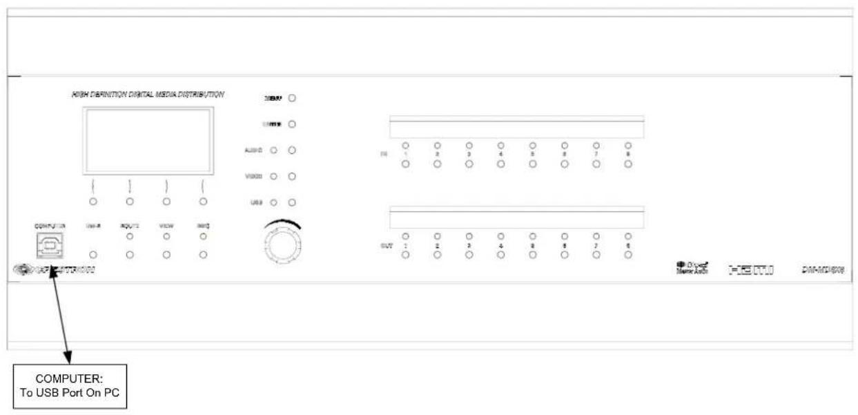
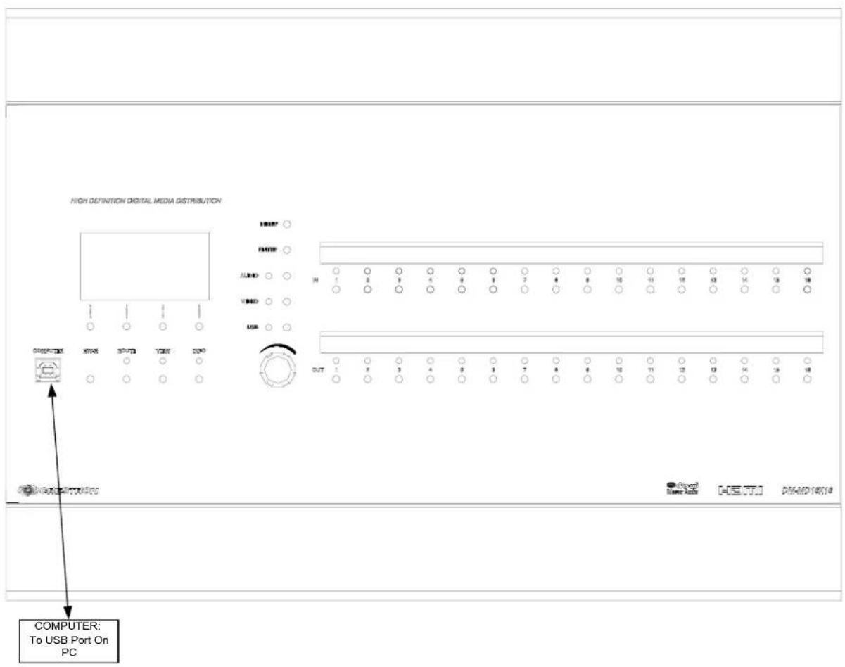
Make the necessary connections as called out in the illustration that follows this paragraph. For details on making connections to installed DM input cards and DM output cards, refer to "Appendix A: Hardware Hookup for DM Cards" on page 70.
Apply power after all connections have been made.
When making connections to the DM switcher, use Crestron power supplies for Crestron equipment.
Hardware Connections for the DM-MD8X8, Front
Hardware Connections for the DM-MD16X16, Front
Hardware Connections for the DM-MD32X32, Front

Hardware Connections for the DM-MD8X8, Rear

Hardware Connections for the DM-MD16X16 Rear

Hardware Connections for the DM-MD32X32Rear
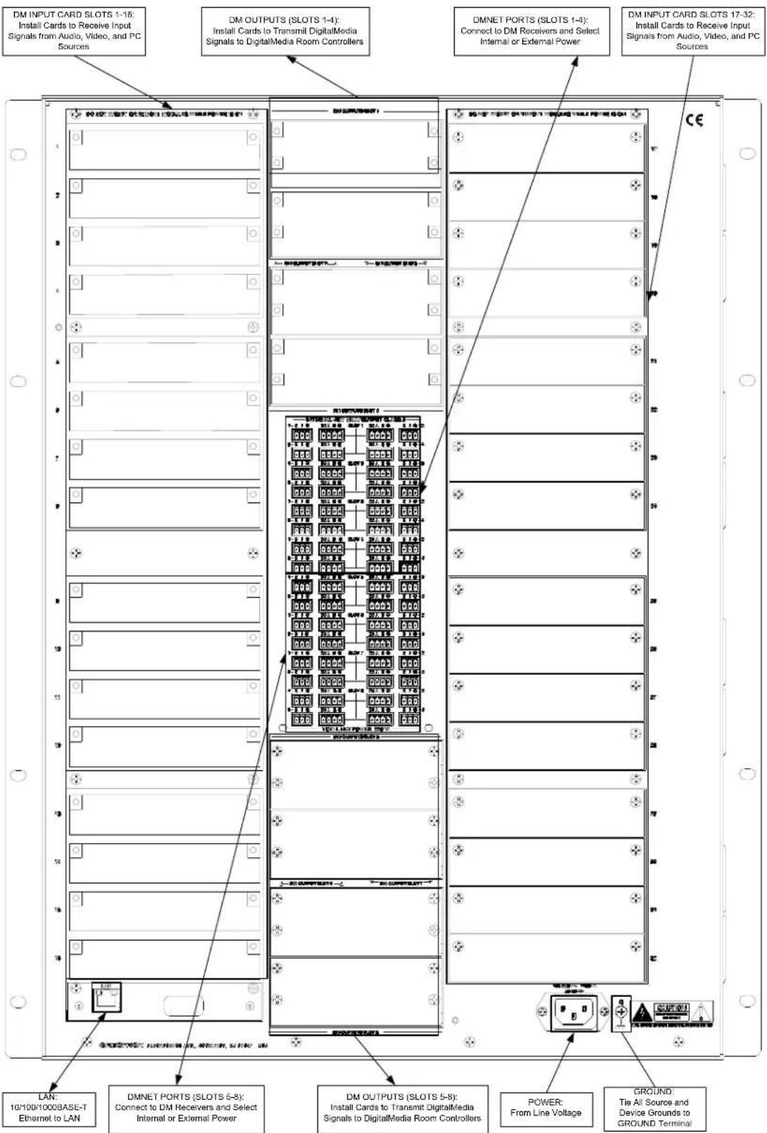
NOTE: The actual configuration of the output cards are specified during ordering. For details on output connections, refer to “Output Connections” on page 82.
NOTE: Ensure the unit is properly grounded by connecting the chassis ground lug to an earth ground (building steel).
NOTE: For optimum performance, Crestron strongly recommends using DM cable or CresFiber, available from Crestron. Other high-quality fiber optic cable (such as InfiniCor300) may also be used with varying performance.
NOTE: When using fiber, it is recommended that you have at least two spare fibers for each location. DM fiber components use SC multimode connectors.
DMNet Power
Devices connected to each DMNet port can receive power from the DM switcher's internal power supply or from an external power supply such as the C2N-SPWS300.
The DMNet ports are preconfigured for operation using the DM switcher's internal power supply.
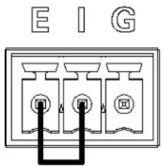
To power a DMNet port externally from a Cresnet 24 VDC power supply, connect the power supply to the E (External) and G (Ground) pins on the EIG connector as shown in the following diagram.
Providing DMNet Power Externally

To power a DMNet port using the DM switcher's internal power supply, install a jumper on the EIG connector from the E (External) pin to the I (Internal) pin as shown in the following diagram.
Providing DMNet Power Internally
Label the Buttons
Use Crestron Engraver software to print custom labels for the DM switcher's front panel buttons and LEDs. Crestron recommends printing on 100-pound paper. Paper with a weight less than 100 pounds will tend to crumple while sliding in, while paper with a weight of more than 100 pounds may not fit.
Configuration
After making all hardware connections, the DM switcher must be configured for operation. The DM switcher can be configured from the DM switcher's front panel using Installer Tools or from a PC using Crestron Toolbox. This document contains instructions for using Installer Tools. For information on using Crestron Toolbox to configure the DM switcher, refer to the Crestron Toolbox help file.
Open Installer Tools
To open Installer Tools:
- Press the MENU button.
- Enter the password. The default password is 1234.
a. Use the selection knob and the soft buttons labeled ◀ and ▶ to enter the password.
Enter Password
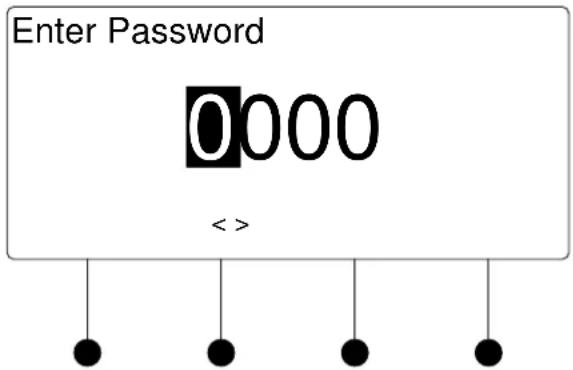
NOTE: If the password contains digits greater than 0 and less than 9, the IN buttons (1 through 8) can be used to enter the password.
b. Turn the selection knob until the correct digit is displayed.
c. Press the ▶ button to move the cursor to the next digit and select the next digit in the password with the volume control. Press the ◀ button to move to the previous digit.
d. Press the ENTER button once the password is displayed. If an incorrect password is entered, the display will show "Invalid Password". Press the soft button labeled OK to exit Installer Tools.
The password can be changed or disabled. For information on changing or disabling the password, refer to “Password” on page 50 for more information.
The Installer Tools menu is displayed.
Installer Tools

Installer Tools is separated into six sections:
- Inputs: Configure and view the settings of input cards installed on the DM switcher.
➢ Outputs: Configure and view the settings of the output cards installed on the DM switcher.
Network: Configure and view the Ethernet settings of the DM switcher.
➢ Control: Configures and views the settings of the DM switcher front panel.
Message Log: Displays messages contained in the DM switcher message log.
➢ Commission System: Manages HDCP keys and optimizes EDID settings for devices connected to the DM switcher.
NOTE: Changes made to any setting will only be saved upon exiting Installer Tools. For instructions on exiting Installer Tools, refer below.
Exit Installer Tools
To exit Installer Tools, press the MENU button. Press the soft button labeled Yes to save any changes and exit Installer Tools or press the soft button labeled No to return to Installer Tools.
Inputs
The Inputs section of Installer Tools is used to configure and view information about input cards installed on the DM switcher. Any changes made to the Inputs section will be saved upon exiting Installer Tools. For more information on exiting Installer Tools, refer to “Exit Installer Tools” above.
To open the Inputs section of Installer Tools:
- Open Installer Tools as described on page 41.
- Turn the selection knob to highlight Inputs and press the ENTER button. A list of installed input cards will be displayed.
Input Setup

- To configure an input, turn the selection knob to highlight an input and press the ENTER button.
For instructions on configuring a specific input card model, refer to "Appendix B: Input Card Configuration" on page 85.
- To exit the Inputs section and return to Installer Tools, press the MENU button.
Outputs
The Outputs section of Installer Tools is used to view information about output cards installed on the DM switcher. Any changes made to the Outputs section will be saved upon exiting Installer Tools. For more information on exiting Installer Tools, refer to “Exit Installer Tools” on page 42.
To open the Outputs section of Installer Tools:
-
Open Installer Tools as described on page 41.
-
Turn the selection knob to highlight Outputs and press the ENTER button. A list of outputs will be displayed.
Output Setup
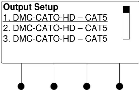
- To configure an output, turn the selection knob to highlight an output and press the ENTER button.
For instructions on configuring a specific output card, refer to "Appendix C: Output Configuration" on page 170.
- To exit the Outputs section and return to Installer Tools, press the MENU button.
Network
The Network section of Installer Tools is used to configure the DM switcher for use on an Ethernet network. Any changes made to the Network section will be saved upon exiting Installer Tools. For more information on exiting Installer Tools, refer to "Exit Installer Tools" on page 42.
Open Network Section
To open the Network section of Installer Tools:
- Open Installer Tools as described on page 41.
- Turn the selection knob to highlight Network and press the ENTER button. A list of functions will be displayed.
Network Functions

flowchart
graph TD
    A["Network Setup"] --> B["Ethernet Link"]
    A --> C["IP Address"]
    A --> D["Subnet Mask"]
    B --> E["●"]
    C --> F["●"]
    D --> G["●"]
    E --> H["●"]
    F --> I["●"]
    G --> J["●"]
NOTE: The image shown above will only be displayed if DHCP is disabled. If DHCP is enabled (default setting), the display will show the functions DHCP, Hostname and Control System IP ID. For information on enabling or disabling DHCP, refer to “DHCP” on page 46.
Ethernet Link
The front panel can display the status of the DM switcher's Ethernet connection (“Online” or “Offline”). To view the status of the Ethernet connection:
- Open the Network section as described above.
- Turn the selection knob to highlight Ethernet Link and press the ENTER button to display the status of the Ethernet connection.
- Press the MENU button to return to the Network section.
IP Address
DM switchers use TCP/IP communications for communications between network devices, the Crestron control system and other devices. The IP address can be obtained from a DHCP server or manually set. For information on using DHCP to obtain an IP address, refer to “DHCP” on page 46. To view or set the IP address:
- Open the Network section as described above.
- Turn the selection knob to highlight IP Address and press the ENTER button to display the IP Address. If DHCP is disabled, controls for changing the IP address will be displayed as shown in the following diagram.
Set IP Address
Edit IP Address
Use Softbutton to select. The use Knob to edit. Press ENTER to accept.
![[000] 000. 000. 000](/content/2026/05/1055891/images/95d06dc5b9d25aa15868b5ab769a93d7b07de2f82b02909b85fdcfcbe0056bee.jpg)
- Press the soft button under the octet to be adjusted.
- Turn the selection knob to the desired number.
- Repeat for each octet until the IP address is displayed.
NOTE: Since the DM switcher reserves a range of IP addresses during configuration, certain IP addresses cannot be used. Refer to “Ethernet Setup” on page 32 for more information.
- To save the IP address and return to the Network section, press the ENTER button. To cancel the operation and return to the Network section, press the MENU button.
Set the Subnet Mask
DM switchers can be configured to use a Subnet Mask for TCP/IP communications. To view or set the address of the Subnet Mask:
- Open the Network section as described on page 44.
- Turn the selection knob to highlight Subnet Mask and press the ENTER button to display the address of the Subnet Mask. If DHCP is disabled, controls changing the address will be displayed as shown in the following diagram.
Set Subnet Mask
Edit Subnet Mask
Use Softbutton to select.
The use Knob to edit.
Press ENTER to accept.
[000] 000. 000.000

natural_image
Simple diagram of four black dots suspended by vertical lines (no text or symbols)- Press the soft button under the octet to be adjusted.
- Turn the selection knob to the desired number.
-
Repeat for each octet until the Subnet Mask address is displayed.
-
To save the Subnet Mask address and return to the Network section, press the ENTER button. To cancel the operation and return to the Network section, press the MENU button.
Set the Default Router
DM switchers can be configured to use a Default Router for TCP/IP communications. To view or set the address of the Default Router:
- Open the Network section as described on page 44.
- Turn the selection knob to highlight Default Router and press the ENTER button to display the address of the Default Router. If DHCP is disabled, controls for changing the address will be displayed as shown in the following diagram.
Set Default Router
Edit Default Router Use Softbutton to select. The use Knob to edit. Press ENTER to accept.
[000]
000.
000.
000

natural_image
Simple diagram of five black dots suspended by vertical lines (no text or symbols)- Press the soft button under the octet to be adjusted.
- Turn the selection knob to the desired number.
- Repeat for each octet until the Default Router address is displayed.
- To save the Default Router address and return to the Network section, press the ENTER button. To cancel the operation and return to the Network section, press the MENU button.
DHCP
A DM switcher's IP address can be obtained from a DHCP server or manually set using Crestron Toolbox. The default setting for the DHCP mode is "On". For information on manually setting the IP address, refer to "IP Address" on page 44. To set the DHCP mode:
- Open the Network section as described on page 44.
- Turn the selection knob to highlight DHCP and press the ENTER button to display the DHCP controls.
DHCP Settings

- Turn the selection knob to highlight On or Off. The current setting is indicated with an asterisk (*).
- To save the setting and return to the Network section, press the ENTER button. To cancel the operation and return to the Network section, press the MENU button.
Hostname
A DM switcher can be recognized by its hostname in a networked environment. To view and set the hostname:
- Open the Network section as described on page 44.
- Turn the selection knob to highlight Hostname and press the ENTER button to display the Hostname controls.
Hostname

- Select letters (upper and lower-case), numbers, or other characters by turning the selection knob until the desired letter, number, or other character is displayed on the LCD. Valid hostname characters are ASCII letters "a" through "z" (case-insensitive), the digits "0" through "9", and the hyphen. Hostname cannot begin or end with a hyphen. No other symbols, punctuation characters or blank spaces are permitted.
Move the cursor to another position by pressing the soft buttons labeled◀ and ▶. To delete a character, press the soft button marked Del.
NOTE: The maximum length for the hostname is 64 characters.
- After the new name has been entered, press Done to save the name and return to the Network section.
Control System Link
The front panel can display the status of a DM switcher's connection (“Online” or “Offline”) to a control system (corresponding entries on the respective IP tables). To view the status of the Control System Link:
- Open the Network section as described on page 44.
- Turn the selection knob to highlight Control System Link and press the ENTER button to display the status of the connection between the DM switcher and the control system.
- Press the MENU button to return to the Network section.
Control System IP ID
To properly function with a control system, the IP ID of a DM switcher must be set to match the value specified in the SIMPL Windows program and the value on the control system's IP table. To view and set the IP ID:
- Open the Network section as described on page 44.
- Turn the selection knob to highlight Control System IP ID and press the ENTER button to display the Control System IP ID controls. The current IP ID will be displayed.
Control System IP ID

- Turn the selection knob to display the desired IP ID and press the ENTER button to return to the Network section.
Control System IP Address
To properly function with a control system, the IP address of the control system that is controlling the DM switcher must be provided to the DM switcher. To view and set the Control System IP Address:
- Open the Network section as described on page 44.
- Turn the selection knob to highlight Control System IP Address and press the ENTER button to display the Control System IP Address controls. If previously entered, the IP address of the control system will be displayed.
Control System IP ID
Edit Ctrl Sys IP Address
Use Softbutton to select.
Then use Knob to edit.
Press ENTER to accept.
[177] 20.
165.
52

natural_image
Simple diagram of four black dots suspended by vertical lines (no text or symbols)- Press the soft button under the octet to be adjusted.
- Turn the selection knob to the desired number.
- Repeat for each octet until the Control System IP Address is displayed.
- To save the Control System IP Address and return to the Network section, press the ENTER button. To cancel the operation and return to the Network section, press the MENU button.
MAC Address
The DM switcher can display its MAC address. To view the MAC address:
- Open the Network section as described on page 44.
- Turn the selection knob to highlight MAC Address and press the ENTER button to display the MAC Address.
- Press the MENU button to return to the Network section.
Control
The Control section of Installer Tools is used to configure the front panel of the DM switcher. Any changes made to the Control section will be saved upon exiting Installer Tools. For more information on exiting Installer Tools, refer to “Exit Installer Tools” on page 42.
Open Control Section
To open the Control section of Installer Tools:
- Open Installer Tools as described on page 41.
- Turn the selection knob to highlight Control and press the ENTER button. A list of functions will be displayed.
Control Functions
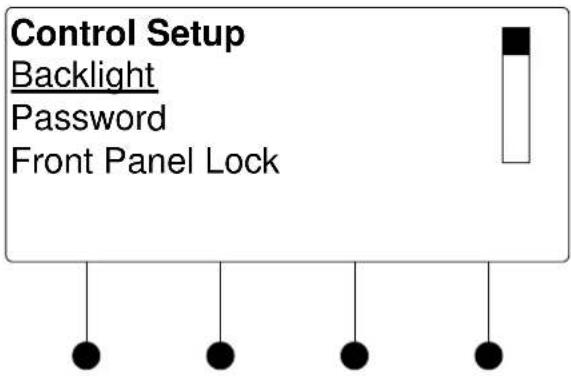
Backlight
The brightness of the display's backlight can be adjusted. To set the backlight level:
- Open the Control section as described on page 49.
- Turn the selection knob to highlight Backlight and press the ENTER button to display the Backlight controls. The current setting is underlined.
Backlight Controls

flowchart
graph TD
    A["Backlight"] --> B["Select Backlight Level"]
    B --> C["High Med Low"]
- Press the soft button under the desired backlight brightness.
- Press the ENTER button to save the backlight brightness and return to the Control section.
Password
The front panel password can be changed. To set a new password:
- Open the Control section as described on page 49.
- Turn the selection knob to highlight Password and press the ENTER button to display the Password controls. The current password is displayed.
Password Controls

- Use the selection knob and the soft buttons labeled ◀ and ▶ to enter the password.
- Turn the selection knob until the correct digit is displayed.
- Press the ▶ button to move the cursor to the next digit and select the next digit in the password with the volume control. Press the ◀ button to move to the previous digit.
- When the password is displayed, press the ENTER button to save it and return to the Control section.
NOTE: Setting the password to 0000 will remove password protection from Installer Tools.
Front Panel Lock
The front panel controls of the DM switcher can be locked to prevent changes to signal routings. However, signal and routing information can still be displayed. To lock the front panel controls:
- Open the Control section as described on page 49.
- Turn the selection knob to highlight Front Panel Lock and press the ENTER button to display the Front Panel Lock controls. The current setting is displayed.
Front Panel Lock Controls

-
Turn the selection knob to highlight Lock or Unlock. The current setting is indicated with an asterisk (*).
-
To save the setting and return to the Control section, press the ENTER button. To cancel the operation and return to the Control section, press the MENU button.
Restore Defaults
The DM switcher's default settings can be restored from the front panel. Restoration can be set to restore all defaults or just the audio and video settings. To restore default settings:
- Open the Control section as described on page 49.
- Turn the selection knob to highlight Restore Defaults and press the ENTER button to display the Restore Defaults controls.
Restore Defaults Controls
Restore Defaults Audio/Video settings only All settings
- Turn the selection knob to highlight the defaults to be restored and press the ENTER button.
- A confirmation message will be displayed. To continue restoring the default settings, press the soft button labeled Yes. To cancel restoring the default settings and return to the Restore Defaults control, press the soft button labeled No.
- To cancel the operation and return to the Restore Defaults control, press the MENU button.
About
Information about the DM switcher's hardware and firmware can be viewed on the front panel. To view information about the DM switcher:
- Open the Control section as described on page 49.
- Turn the selection knob to highlight About and press the ENTER button to display the About controls.
About Controls
About Hardware Configuration Firmware Configuration
- Turn the selection knob to highlight Hardware Configuration or Firmware Configuration and press the ENTER button.
a. For Hardware Configuration:

flowchart
graph TD
    A["<< >>"] --> B["●"]
    A --> C["●"]
    A --> D["●"]
    A --> E["●"]
i. Press the soft buttons labeled ◀◀ and ▶▶ to display the data that does not fit on the display.
ii. Turn the selection knob to view other data.
iii. Press the MENU button to return to the About controls.
b. For Firmware Configuration:

i. Turn the selection knob to view other data.
ii. Press the MENU button to return to the About controls.
- Press the MENU button to return to the Control section.
Message Log
The Message Log section of Installer Tools contains system messages from the DM switcher.
Open Message Log
To open the Message Log section of Installer Tools:
- Open Installer Tools as described on page 41.
- Turn the selection knob to highlight Message Log and press the ENTER button. The Message Log will be displayed.
Message Log
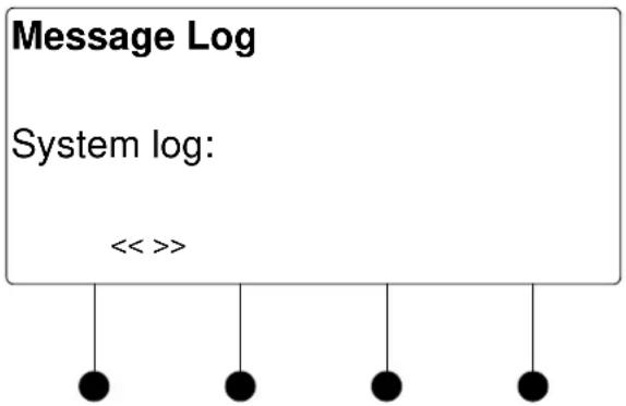
flowchart
graph TD
    A["Message Log"] --> B["System log: << >>"]
    B --> C["●"]
    B --> D["●"]
    B --> E["●"]
    B --> F["●"]
- Press the soft buttons labeled ◀◀ and ▶▶ to display the data that does not fit on the display.
- Turn the selection knob to scroll through the list of messages.
- Press the MENU button to return to Installer Tools.
Commission System
The Commission System section of Installer Tools is used to manage HDCP and EDID capabilities of sources and displays connected to the DM switcher.
Open Commission System
To open the Commission System section of Installer Tools:
- Open Installer Tools as described on page 41.
- Turn the selection knob to highlight Commission System and press the ENTER button. A list of functions will be displayed.
Commission System Functions

HDCP Check
The switcher can test HDMI sources and displays for switching limitations due to HDCP keys. The number of HDCP keys specify the number of display devices that can be connected to a source over HDMI using HDCP authentication. To run an HDCP check:
- Open the Commission System section as described on page 54.
- Turn the selection knob to highlight HDCP Check and press the ENTER button.
Confirmation for HDCP Check
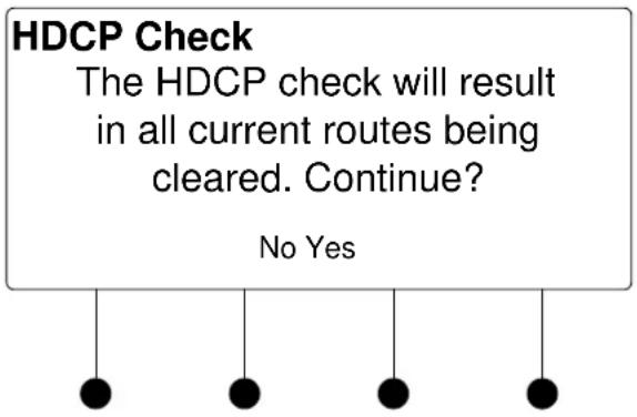
Running an HDCP check will disconnect any audio and video routes that are currently set. To proceed with the HDCP check, press the soft button labeled Yes. To cancel the HDCP check, press the soft button labeled No.
Instructions for HDCP Check

- Verify that all source and display devices are powered on. Press the soft button labeled OK to continue.
- The display will show the input cards that will be tested. Press the soft button labeled OK to begin the HDCP check.
Analysis of Cards to Be Tested
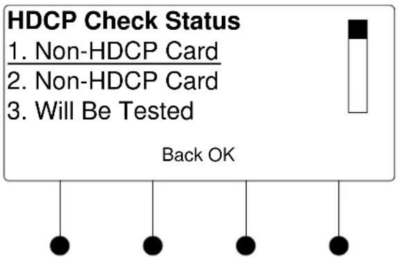
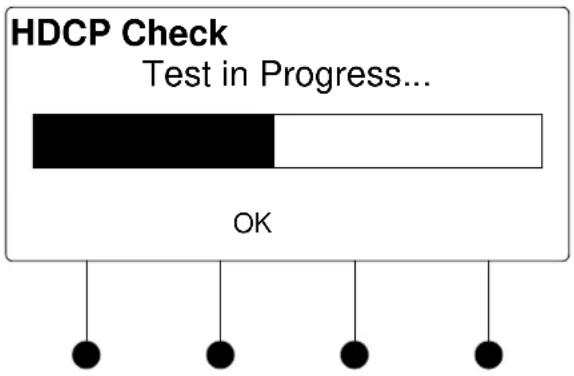
A progress bar will be displayed to show the progress of the HDCP check.
HDCP Check in Progress
When the check is complete the results will be displayed.
HDCP Check Results

flowchart
graph TD
    A["DONE"] --> B["●"]
    C["LIST"] --> D["●"]
    E["●"] --> F["●"]
    G["●"] --> H["●"]
If the number of displays in use exceeds the number of devices supported by the source, an error message will be displayed. To view the results for each input source, press the soft button labeled LIST. Otherwise, press the soft button labeled DONE to return to the Commission System section.
• View HDCP Check Results
HDCP Check Results
HDCP Check Results
Input 1 (DVD)
Max HDCP Keys: 9
Possible Destinations: 8
DONE << >>

natural_image
Simple diagram of four black dots suspended by strings (no text or symbols)a. Press the soft buttons labeled ◀◀ and ▶▶ to scroll through the results for other inputs.
b. Press the soft button labeled DONE to return to the Commission System section.
Data Rate Check
The switcher can test the cable run on each output to determine the maximum data rate that can be delivered. To run a data rate check:
- Open the Commission System section as described on page 54.
- Turn the selection knob to highlight Data Rate Check and press the ENTER button. A screen showing available cable types will be displayed.
Confirm DM Cable Type
Confirm DM Cable Type
* Digital Media Category 6 Category 5e
Next
Cable types that were chosen when output ports were configured (refer to "DM CAT Output Information" on page 171) and selected for testing are shown with an asterisk (*).
- If necessary, turn the selection knob to highlight the cable type to be tested and press the ENTER button to confirm.
NOTE: Selecting a different cable type will cause the other cable types to be deselected. The parameters of the newly selected cable type will be used for testing the outputs specified in the next step.
- Press the soft button labeled Next to continue.
Select Outputs to Test
Select Outputs to Test
* Kid's Room
* Living Room
* Kitchen
All
None Next

natural_image
Simple diagram of four black dots suspended by vertical lines (no text or symbols)- Turn the selection knob to highlight an output for testing and press the ENTER button to mark it. Outputs to be tested are marked with an asterisk (*).
To test all of the outputs, press the soft button labeled All.
To remove all of the outputs from the test list, press the soft button labeled None.
To remove an output from the test, highlight the output with the selection knob and press the ENTER button.
NOTE: If an output uses a cable type that is different than the cable type selected in the previous step, remove it from the list of outputs to be tested. Repeat the data rate check using the installed cable type.
After the outputs to be tested are selected, press the soft button labeled Next.
- Verify that all sources and selected outputs are powered on and press the soft button labeled OK to begin the data rate check. A progress bar will be displayed to show the progress of the data rate check.
Data Rate Check in Progress
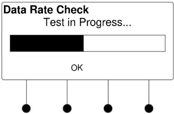
When the test is complete the results will be displayed.
Data Rate Check Results-Success

If an error was encountered during the data rate check, an error message will be displayed.
Data Rate Check Results-Error
Data Rate Check - Error Kid's Room – No Video Living Room – No Video Kitchen – 2.22Gbps
Resolution Done
- Turn the selection knob to scroll through the test results. To view the results expressed in resolution, press the soft button labeled Resolution. To view the results in terms of data rate, press the soft button labeled Data Rate.
- Press the soft button labeled Done to return to the Commission System section.
EDID
EDID is a piece of data that HDMI receivers use to indicate their capabilities to the HDMI sources.
The DM switcher routes DigitalMedia (DM) signals from any of the input cards to one or more of the output channels. According to the HDMI standard, HDMI sources are expected to only deliver audio and video formats that are supported by the destination. To do this, the DM switcher reads the EDID information from devices connected to the outputs and determines the video resolutions and audio format to send to the input cards to program EDID on the input card receivers.
Using Crestron Toolbox, the DM switcher can be configured to use several different algorithms to determine what EDID information is sent to each source:
- Copy Display
Copy Display
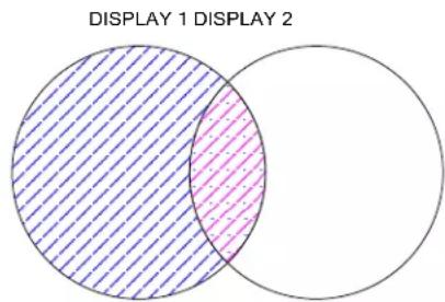
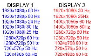
COMBINED
1920x1080p 60 Hz
1920x1080p 50 Hz
1920x1080p 24 Hz
1920x1080i 30 Hz
1920x1080i 25 Hz
1280x720p 60 Hz
1280x720p 50 Hz
720x576p 50 Hz
720x480p 60 Hz
The EDID information from a DigitalMedia or HDMI output is copied to the input verbatim. This means that all resolution, audio and vendor information will be from that display.
- Best Common
Best Common

other
| DISPLAY 1 Only | DISPLAY 2 Only | DISPLAY 1 & DISPLAY 2 | DISPLAY 2 & DISPLAY 2 | | -------------- | -------------- | --------------------- | --------------------- | | 1920x1080i 60 Hz | 1920x1080i 30 Hz | 1920x1080i 60 Hz | 1920x1080i 30 Hz | | 1920x1080i 50 Hz | 1920x1080i 25 Hz | 1920x1080i 50 Hz | 1920x1080i 25 Hz | | 1920x1080i 24 Hz | 1920x1080i 30 Hz | 1920x1080i 24 Hz | 1920x1080i 30 Hz | | 1920x1080i 30 Hz | 1920x1080i 25 Hz | 1920x1080i 30 Hz | 1920x1080i 25 Hz | | 1920x1080i 25 Hz | 1280x720p 60 Hz | 1280x720p 60 Hz | 1400x1050p 60 Hz | | 1280x720p 60 Hz | 1280x720p 50 Hz | 1280x720p 50 Hz | 1400x1050p 50 Hz | | 720x576p 50 Hz | 720x480p 60 Hz | 720x576p 50 Hz | 1280x720p 60 Hz | | 720x480p 60 Hz | | 720x480p 60 Hz | 1280x720p 50 Hz | | BEST COMMON | BEST COMMON | BEST COMMON | BEST COMMON | | 1920x1080i 30 Hz | | | | | 1920x1080i 25 Hz | | | | | 1280x720p 60 Hz | | | | | 1280x720p 50 Hz | | | | | 720x576p 50 Hz | | | | | 720x480p 60 Hz | | | |Only resolutions that are available in all of the displays that are connected will be transmitted to the source. This ensures that any video signal coming in from the source will be able to be shown on all displays. If certain resolutions are only available on a subset of the displays, they will be omitted.
- Manual
Use Crestron Toolbox to select which resolutions are transmitted to the source.
"Best Common" is initially set to use information from all displays, but can be modified to use information from just a subset of displays by deselecting them in Crestron Toolbox.
By managing which displays are used for the EDID calculations, you can maximize the resolution of each source while ensuring that the source can be shown on each display where it is needed.
The EDID calculations also affect audio formats. Each HDMI receiver sends its supported audio formats to the source in the following format:
For example, a 5.1 channel audio processor may have the following audio EDID information:
• Linear PCM, 2ch, 32/44.1/48kHz
• AC3, 6ch, 32/44.1/48kHz
• DTS, 6ch, 32/44.1/48kHz
Under "Best Common", the same rules apply to audio as video.
For more information, refer to the Crestron Toolbox help file.
Uploading and Upgrading
Crestron recommends using the latest programming software and that each device contains the latest firmware to take advantage of the most recently released features. However, before attempting to upload or upgrade it is necessary to establish communication. Once communication has been established, files (for example, programs or firmware) can be transferred to the control system (and/or device). Finally, program checks can be performed (such as changing the device ID or creating an IP table) to ensure proper functioning.
Establishing Communication
Use Crestron Toolbox for communicating with the DM switcher; refer to the Crestron Toolbox help file for details. There are two methods of communication.
USB
NOTE: Required for initial setup of Ethernet parameters.
USB Communication

flowchart
graph LR
    A["PC Running Crestron Toolbox"] <-->|USB| B["DM Switcher"]
The COMPUTER port on the DM switcher connects to the USB port on the PC via the included Type A to Type B USB cable.
- Use the Address Book in Crestron Toolbox to create an entry using the expected communication protocol (USB). When multiple USB devices are connected, identify the DM switcher by entering "DM-MD8X8", "DM-MD16X16", or "DM-MD32X32" in the Model textbox, the unit is serial number in the Serial textbox or the unit is hostname in the Hostname textbox. The hostname can be found in the "System Info" window in the section marked Ethernet however, communications must be established in order to see this information in the "System Info" window.
- Display the DM switcher's "System Info" window (click the icon); communications are confirmed when the device information is displayed.
NOTE: Required for operation with a Crestron control system.
Ethernet Communication

flowchart
graph LR
    A["PC Running Crestron Toolbox"] <--> B["Ethernet"]
    B --> C["DM Switcher"]
- Establish USB communication between the DM switcher and PC.
- Enter the IP address, IP mask and default router of the DM switcher via the Crestron Toolbox (Functions | Ethernet Addressing); otherwise enable DHCP.
TCP/IP
NOTE: Use the Device Discovery Tool in Crestron Toolbox to detect all Ethernet devices on the network and their IP configuration. The tool is available in Toolbox version 1.15.143 or later.
- Confirm Ethernet connections between the DM switcher and PC. If connecting through a hub or router, use CAT5 straight through cables with 8-pin RJ-45 connectors. Alternatively, use a CAT5 crossover cable to connect the two LAN ports directly without using a hub or router.
- Use the Address Book in Crestron Toolbox to create an entry for the DM-MD8X8, DM-MD16X16, or DM-MD32X32 with the DM switcher's TCP/IP communication parameters.
- Display the "System Info" window (click the icon) and select the DM switcher's entry.
Programs and Firmware
Program or firmware files may be distributed from programmers to installers or from Crestron to dealers. Firmware upgrades are available from the Crestron website as new features are developed after product releases. One has the option to upload programs via the programming software or to upload and upgrade via the Crestron Toolbox. For details on uploading and upgrading, refer to the Crestron Studio help file, SIMPL Windows help file, or the Crestron Toolbox help file.
Crestron Studio or SIMPL Windows
Firmware
If a Crestron Studio (or SIMPL Windows) program is provided, it can be uploaded to the control system using Crestron Studio (or SIMPL Windows) or Crestron Toolbox.
Check the Crestron website to find the latest firmware. (New users may be required to register to obtain access to certain areas of the site, including the FTP site.)
Upgrade the DM switcher's firmware via Crestron Toolbox.
- Establish communication with the DM switcher and display the “System Info” window.
- Select Functions | Firmware... to upgrade the DM switcher's firmware.
Program Checks
Actions that can be performed on a DM switcher vary depending on whether it is connected via USB or Ethernet.
USB Connections
For USB connections, using Crestron Toolbox, display the "System Info" window (click the icon) and select the Functions menu to display actions that can be performed on the DM switcher.
Ethernet Connections
For Ethernet connections, using Crestron Toolbox, display the "System Info" window (click the icon) and select the Functions menu to display actions that can be performed on the DM switcher.
Be sure to use Crestron Toolbox to create the DM switcher's IP table.
- Select Functions | IP Table Setup.
- Add, modify or delete entries in the IP table. The DM switcher can have only one IP table entry.
- A defined IP table can be saved to a file or sent to the device.
Edit the control system's IP table to include an entry for the DM switcher. The entry should list the DM switcher's IP ID (specified on the DM switcher's IP table) and the internal gateway IP address 127.0.0.1.
DM Tool
In the Crestron Toolbox Address Book, select the DM switcher. Then use the DM Tool to configure EDID, HDCP or to troubleshoot AV on the DM switcher. Refer to the help file for additional information.
DM Tool

Operation
Operating Modes
A DM switcher can operate in the Route mode, the View mode, or the Info mode.
The DM switcher can also be controlled from Crestron Toolbox. For more information, refer to the Crestron Toolbox help file.
Route Mode
The Route mode uses the front panel controls to route input signals to outputs. Press the ROUTE button to activate the Route mode.
- When in the Route mode, pressing an input button will show the outputs that are connected to the input.
- Audio, video, and USB portions of an input can be routed independently. For more information, refer to "Route Mode" below.
View Mode
The View mode uses the front panel controls to view routing information for inputs and outputs.
Routing information for audio, video, and USB portions of an input can be viewed independently. For more information, refer to “View Mode” on page 65.
Info Mode
The Info mode uses the front panel controls to view data about signals that are passed through the inputs and outputs of the DM switcher. For more information, refer to “Info Mode” on page 66.
Route Mode
Signals coming in to the DM switcher can be switched to single or multiple outputs. Additionally, the audio, video, and USB portions of an input signal can be switched simultaneously or separately.
To enter the Route mode, press the ROUTE button. The ROUTE LED will light.
Switch Audio, Video, and USB Simultaneously
- Press the AUDIO, VIDEO, and USB buttons to select the audio, video, and USB portions for switching. The respective LEDS will light.
NOTE: If an output has different audio, video, or USB portions, a new route will cause the audio and USB portions on the output to switch to the newly selected video input.
- Press the button corresponding to the input to be switched. The LED of the selected input will light.
To turn off an output, deselect the input. The display will show "IN None" and the input LEDs will be extinguished.
- Press the button(s) corresponding to the output(s) to be switched. The LED(s) of the selected output(s) will flash.
If a button press will result in changing the current routing, the LEDs of the newly selected outputs will flash and the display will state “Press ENTER to Route”.
- Press ENTER to make the connection(s) shown on the front panel.
Switch Audio, Video & USB Separately
Changes made on the front panel are made only after the ENTER button is pressed. If you do not press ENTER, the connection is not made.
Only one input can be routed at a time. Pressing a different input button will lose any routing plans that were not confirmed by pressing the ENTER button.
NOTE: If ENTER has not been pressed, you can go back and “undo” changes made to the current routing.
-
Repeat for any other routes to be changed.
-
Press the AUDIO, VIDEO, or USB buttons to select the audio, video, or USB portions to be switched. The respective LEDS will light.
NOTE: When audio is switched independently, the signal is 2-channel audio.
- Press the button corresponding to the input to be switched. The LED of the selected input will light.
To turn off an output, deselect the input. The display will show "IN None" and the input LEDs will be extinguished.
- Press the button(s) corresponding to the output(s) to be switched. The LED(s) of the selected output(s) will light.
If a button press will result in changing the current routing, the LEDs of the newly selected outputs will flash and the display will state "Press ENTER to Route".
- Press ENTER to make the connection(s) shown on the front panel.
Changes made on the front panel are made only after the ENTER button is pressed. If you do not press ENTER, the connection is not made.
Only one input can be routed at a time. Pressing a different input button will lose any routing plans that were not confirmed by pressing the ENTER button.
NOTE: If ENTER has not been pressed, you can go back and "undo" changes made to the current routing.
- Repeat for any other routes to be changed.
View Mode
Use the View Mode to view routing information for inputs and outputs. To select the View mode, press the VIEW button.
View Source Routing
-
Press an input signal button to display all of the outputs that are connected to it.
-
Press AUDIO, VIDEO, or USB to see where the audio, video, or USB portions of an input signal are routed.
-
Press an output signal button to display the input signal that is connected. All outputs that are receiving the same input signal are also displayed.
-
Press AUDIO, VIDEO, or USB to see the input that is providing the audio, video, or USB portions of the output signal.
View Output Routing
Info Mode
Use the Info mode to view information about the signal on an input or output. Depending on the input selected, available information can include the name of the input, the detected resolution, the detected video type, the detected frame rate, the detected aspect ratio, the HDCP state, and the deep color setting. To select the Info mode, press the INFO button. If an input port is receiving a signal from its connected source, the accompanying LED will illuminate.
View Input Information
- Press an input button to display information about the input signal. The accompanying LED will flash.
NOTE: If the DMC-VID4 is selected, each composite video input can be selected for viewing by pressing the soft button of the desired input.
-
Turn the selection knob to display available information.
-
Press another input button to view its information.
-
Press an output button to display information about the output signal. The accompanying LED will flash.
NOTE: If a DM output with HDMI is selected, information for the DM port and the HDMI port can be selected for viewing by pressing the soft button of the desired output.
-
Turn the selection knob to display available information.
-
Press another output button to view its information.
Problem Solving
Troubleshooting
The following table provides corrective action for possible trouble situations. If further assistance is required, please contact a Crestron customer service representative.
DM Switcher Troubleshooting
| TROUBLE | POSSIBLE CAUSE(S) | CORRECTIVE ACTION |
| Incorrect Audio or Video displayed. | Audio is routed separately from video. | Reroute audio together with video. |
| Distorted audio or video. | Source does not match capabilities of destination. | Use Crestron Toolbox to manage EDID capabilities of devices in the system. |
| No video. Bandwidth check passes and VIDEO LED on DM-RMC-100 is lit. | “D” cable is incorrectly terminated. | Terminate cable as described in “DigitalMedia Cable” on page 28. |
| No video displayed, but audio is heard. | Possible HDCP error. | Check control system error log, or DM switch for HDCP errors. |
| HDCP Check Failure Message during commissioning. | Violation of HDCP rules (number of display devices exceeds the source’s number of allowed displays). | Disconnect displays that may not be used with source during run time and repeat HDCP check. |
| Replace source device with a device that allows more displays to be connected. | ||
| Violation of HDCP rules (device depth exceeds allowable depth specification). | Reconfigure signal path to remove midpoint devices that increase overall device depth. | |
| Bandwidth Test Failure Message during commissioning. | Poor cable connection to a DM-RMC-100 (on the “D” line). | Verify that cable is not crimped or damaged. |
| DM-DR Repeater or DM-RMC-100 Room Controller do not report to DM switcher. | Poor cable connection to the DM-DR or DM-RMC-100 (on the “D” line). | Verify that cable is not crimped or damaged. |
| No audio output from RCA connectors on DMC-HD | Source is not providing a 2-channel audio signal. | Replace DMC-HD card with DMC-HD-DSP to provide 2-channel stereo downmix from audio source. |
| Loss of functionality due to electrostatic discharge. | Improper grounding. Check that all ground connections have been made properly. | |
Check Network Wiring
Use the Right Wire
In order to ensure optimum performance over the full range of your installation topology, Crestron Certified Wire and only Crestron Certified Wire may be used. Failure to do so may incur additional charges if support is required to identify performance deficiencies because of using improper wire.
Calculate Power
CAUTION: Use only Crestron power supplies for Crestron equipment. Failure to do so could cause equipment damage or void the Crestron warranty.
CAUTION: Provide sufficient power to the system. Insufficient power can lead to unpredictable results or damage to the equipment. The EIG connector on the DM switcher is used to bring in external power. Additional power is rarely required as switchers provide enough power for their maximum configuration of room controllers and repeaters. Please use the DMNet Power Calculator to help calculate how much power is needed for the system (www.crestron.com/calculators).
CresFiber fiber optic cables provide for longer distances between the DigitalMedia switcher and a DigitalMedia Room Controller. For more information, refer to the latest version of the Crestron DigitalMedia Design Guide (Doc. 4789).
Refer to the following tables for maximum cable lengths using various cables.
Maximum DM Cable Length
| Cable Type: | DM-CBL DigitalMedia Cable | |
| Resolution: | Maximum length without, between, before or after repeaters | Maximum total length using up to 2 repeaters |
| 720p, 1080i, 1080p24 200 ft | (60 m) | 450 ft (137 m) |
| 1024x768 @ 75 Hz | 200 ft (60 m) | 450 ft (137 m) |
| 1080p60 | 150 ft (45 m) | 450 ft (137 m) |
| 1280x1024 @ 75 Hz | 150 ft (45 m) | 450 ft (137 m) |
| 1920x1200 @ 60 Hz | 150 ft (45 m) | 450 ft (137 m) |
| 1600x1200 @ 60 Hz | 125 ft (38 m) | 375 ft (114 m) |
| 1080p60 Deep Color | 100 ft (30 m) | 300 ft (91 m) |
NOTE: All Crestron certified DMNet wiring must consist of two twisted pairs. One twisted pair is the +24V conductor and the GND conductor and the other twisted pair is the A conductor and the B conductor.
Maximum CresFiber Cable Length
| RESOLUTION | CRESFIBER |
| 720p, 1080i, 1080p24 | 1000' (~300 m) |
| 1024 x 768 @ 75 Hz | |
| 1280 x 1024 @ 75 Hz | |
| 1600 x 1200 @ 60 Hz | |
| 1920 x 1200 @ 60 Hz | |
| 1080p60 | |
| 1080p60 Deep Color |
Other fiber optic cable can be used as well.
NOTE: 1080p60 is the most common resolution used in residential installations.
Reference Documents
The latest version of all documents mentioned within the guide can be obtained from the Crestron website (www.crestron.com/manuals). This link will provide a list of product manuals arranged in alphabetical order by model number.
List of Related Reference Documents
| DOCUMENT TITLE |
| Crestron DigitalMedia Design Guide |
| Crestron e-Control Reference Guide |
Further Inquiries
If you cannot locate specific information or have questions after reviewing this guide, please take advantage of Crestron's award winning customer service team by calling Crestron at 1-888-CRESTRON [1-888-273-7876].
You can also log onto the online help section of the Crestron website (www.crestron.com/onlinehelp) to ask questions about Crestron products. First-time users will need to establish a user account to fully benefit from all available features.
Future Updates
As Crestron improves functions, adds new features and extends the capabilities of DM switchers, additional information may be made available as manual updates. These updates are solely electronic and serve as intermediary supplements prior to the release of a complete technical documentation revision.
Check the Crestron website periodically for manual update availability and its relevance. Updates are identified as an “Addendum” in the Download column.
Appendix A: Hardware Hookup for DM Cards
This section contains information for connecting sources and other devices to input and output cards installed on a DM switcher. For installation instructions, refer to the latest version of the card's Installation Guide.
Input Cards
This section contains information on the following input cards:
• DMC-CAT DM CAT Input Card for DM Switchers below.
- DMC-CAT-DSP DM CAT Input Card with Down-mixing for DM Switchers on page 71.
• DMC-DVI DVI/RGB Input Card for DM Switchers on page 72.
• DMC-F DM Fiber Input Card for DM Switchers on page 74.
- DMC-F-DSP DM Fiber Input Card with Down-mixing for DM Switchers on page 75.
• DMC-HD HDMI Input Card for DM Switchers on page 76.
• DMC-HD-DSP HDMI Input Card with DSP for DM Switchers on page 77.
• DMC-SDI SDI Input Card for DM Switchers on page 78.
• DMC-VID4 Security Camera Input Card for DM Switchers on page 79.
- DMC-VID-BNC BNC Analog Video Input Card for DM Switchers on page 79.
- DMC-VID-RCA-A RCA Analog Video Input Card with Analog Audio for DM Switchers on page 81.
- DMC-VID-RCA-D RCA Analog Video Input Card with Digital Audio for DM Switchers on page 81.
Connections for output cards can be found on page 82.
Refer to the following diagrams when connecting sources to DM input cards.
DMC-CAT DM CAT Input Card for DM Switchers
The DMC-CAT is an input card for a DigitalMedia switcher, providing one CAT-type DM input. The DM CAT input enables the connection of a DM transmitter or the output of another DM switcher, with a potential cable length up to 450 feet (137 m) using DigitalMedia cable.
NOTE: For optimum performance, Crestron recommends Crestron DigitalMedia cable.
Additional connections on the card include both HDMI and stereo analog audio loopback outputs. The HDMI output passes the input signal through to feed a local device, or to feed a second DM switcher for output expansion purposes. The analog audio output, which features programmable volume control, breaks out the stereo audio signal from the HDMI input and passes it through to feed a CNX-PAD8A, AAE, or other multi-room audio distribution system.
NOTE: For applications requiring the simultaneous distribution of surround sound and 2-channel audio signals, use model DMC-CAT-DSP.
The DMC-CAT may also be used with the DMCI DigitalMedia Card Interface to provide a DM CAT receiver solution that is perfect for installation in an equipment rack or AV cart, or as a portable display interface. As a DM receiver, and as a DM switcher input card, the DMC-CAT enables EDID signal detection and format management, CEC device control, and audio breakaway.
Hardware Hookup for DMC-CAT DM CAT Input Card for DM Switchers
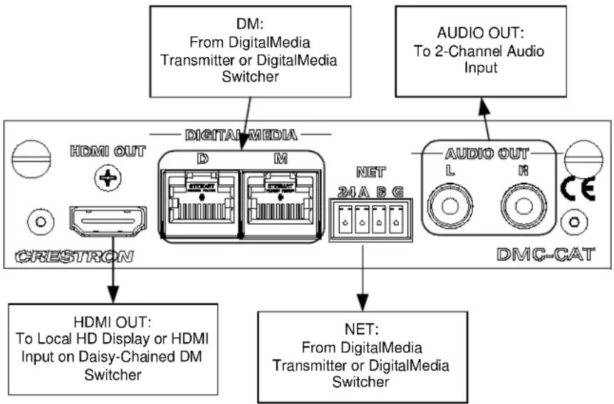
flowchart
graph TD
    A["DM: From DigitalMedia Transmitter or DigitalMedia Switcher"] --> B["DIGITAL MEDIA"]
    C["AUDIO OUT: To 2-Channel Audio Input"] --> D["AUDIO OUT L R CE"]
    B --> E["HDMI OUT: To Local HD Display or HDMI Input on Daisy-Chained DM Switcher"]
    D --> F["NET: From DigitalMedia Transmitter or DigitalMedia Switcher"]
    E --> G["CRESTRON"]
    F --> H["DM-CAT"]
DMC-CAT-DSP DM CAT Input Card with Down-mixing for DM Switchers
The DMC-CAT-DSP is an input card for a DigitalMedia switcher, providing one CAT-type DM input. The DM CAT input enables the connection of a DM transmitter or the output of another DM switcher, with a potential cable length up to 450 feet (137 m) using DigitalMedia cable.
NOTE: For optimum performance, Crestron recommends Crestron DigitalMedia cable.
The DMC-CAT-DSP provides all of the features of the DMC-CAT with the addition of internal DSP processing to enable the simultaneous distribution of uncompressed 7.1 channel HD surround sound and 2-channel audio. The DMC-CAT-DSP is recommended for use with Blu-ray Disc players and other HD sources that output multi-channel surround sound audio via HDMI, allowing the multi-channel signal to reach the surround sound system without requiring any decoding, while also providing a 2-channel down-mix to feed a stereo zone or audio distribution system.
Additional connections on the card include both HDMI and stereo analog audio loop back outputs. The HDMI output simply passes the input signal through to feed a local device, or to feed a second DM switcher for output expansion purposes. The analog audio output, which features programmable volume control, breaks out the stereo audio signal from the HDMI input and passes it through to feed a CNX-PAD8A, AAE, or other multi-room audio distribution system.
The DMC-CAT-DSP may also be used with the DMCI DigitalMedia Card Interface to provide a DM CAT receiver solution that is perfect for installation in an equipment rack or AV cart, or as a portable display interface. As a DM receiver, and as a DM switcher input card, the DMC-CAT-DSP enables EDID signal detection and format management, CEC device control, and audio breakaway.
Hardware Hookup for DMC-CAT-DSP DM CAT Input Card with Down-mixing for DM Switchers

flowchart
graph TD
    A["DM: From DigitalMedia Transmitter or DigitalMedia Switcher"] --> B["DIGITAL MEDIA"]
    C["AUDIO OUT: To 2-Channel Audio Input"] --> D["AUDIO OUT L R CE"]
    B --> E["HDMI OUT: To Local HD Display or HDMI Input on Daisy-Chained DM Switcher"]
    D --> F["NET: From DigitalMedia Transmitter or DigitalMedia Switcher"]
DMC-DVI DVI/RGB Input Card for DM Switchers
The DMC-DVI is an input card for a DigitalMedia switcher, providing one DVI digital video input or analog RGB/Component input, with balanced stereo analog audio. The DMC-DVI handles computer resolutions up to WUXGA 1920 x 1200, as well as HDTV up to 1080p60. Professional balanced/unbalanced audio inputs are included to accept a stereo line level audio signal.
NOTE: DVI-I connection requires an appropriate adapter to accommodate an RGB or YP_bP_r signal. (1) RGB-to-DVI-I adapter is included. YP_bP_r adapter not included.
Additional connections on the card include an HDMI loop back output, and a USB HID port. The HDMI output passes the audio and video input signals through digitally to feed a local device, or to feed a second DM switcher for output expansion purposes. The USB HID host port allows a remote mouse/keyboard connected at the display location, to control a centralized source device (i.e. computer, media server, etc.) at the equipment rack.
Hardware Hookup for DMC-DVI Input Card for DM Switchers
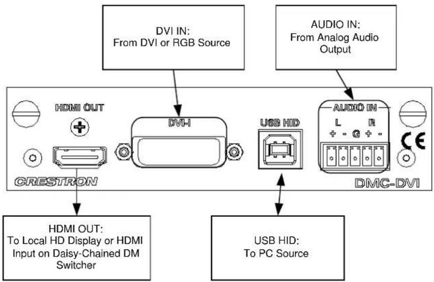
flowchart
graph TD
    A["DVI IN: From DVI or RGB Source"] --> B["DMI OUT"]
    C["AUDIO IN: From Analog Audio Output"] --> D["DMI-DVI"]
    B --> E["GRESTRON"]
    D --> F["USB HID"]
    E --> G["HDMI OUT: To Local HD Display or HDMI Input on Daisy-Chained DM Switcher"]
    D --> H["USB HID: To PC Source"]
    I["USB HID"] --> D
Balanced/unbalanced audio inputs are provided, utilizing five-pin terminal block connectors. For connection details, refer to the following table and diagrams.
Audio Connections
| SIGNAL NAME | BALANCED AUDIO INPUT | UNBALANCED AUDIO INPUT |
| + L + L + | ||
| - | L - | L – signal return, jumper to GND |
| G Shield/Ground Ground | ||
| + R + R + | ||
| - | R - | R – signal return, jumper to GND |
Typical Balanced/Unbalanced Inputs

The BNC output of a wideband RGB switcher such as the Crestron CEN-RGBHV12X4 can be connected to a DMC-DVI using either a BNC-to-DVI adapter (not included) or a BNC-VGA adapter (not included) with the included VGA-DVI adapter to provide further expansion. When connecting sources to the switcher, please make the following connections.
Hardware Hookup, BNC to DVI

flowchart
graph TD
    R["OUT 1"] --> A["+"]
    Q["OUT 1"] --> A
    B["OUT 1"] --> C["⊕"]
    H["OUT 1"] --> D["⊕"]
    V["OUT 1"] --> E["⊕"]
    A --> F["BNC-DVI ADAPTER"]
    C --> F
    D --> F
    E --> F
    F --> G["HDMI OUT"]
    F --> H["USB HD"]
    F --> I["-AUDIO IN"]
    F --> J["L + - α + -"]
    F --> K["CE"]
    style F fill:#f9f,stroke:#333,stroke-width:2px
Port Connections
| SIGNAL TYPE | INPUT SIGNAL | CONNECTS TO |
| RGBHV R | R | |
| G | G | |
| B | B | |
| H | H | |
| V | V | |
| YP_bP_r | Y | G |
| P_b | B | |
| P_r | R | |
| S-video C | R | |
| Y | G | |
| Composite Composite | B | |
DMC-F DM Fiber Input Card for DM Switchers
The DMC-F is an input card for a DigitalMedia switcher, providing one optical fiber type DM input. The DM fiber input enables the connection of a DM transmitter, or the output of another DM switcher, with a potential cable length up to 1000 feet (300 m) using multimode fiber optic cable.
NOTE: For optimum performance, Crestron recommends Crestron DigitalMedia cable.
Additional connections on the card include both HDMI and stereo analog audio loop back outputs. The HDMI output simply passes the input signal through to feed a local device, or to feed a second DM switcher for output expansion purposes. The analog audio output, which features programmable volume control, breaks out the stereo audio signal from the HDMI input and passes it through to feed a CNX-PAD8A, AAE, or other multi-room audio distribution system.
NOTE: For applications requiring the simultaneous distribution of surround sound and 2-channel audio signals, use model DMC-F-DSP.
The DMC-F may also be used with the DMCI DigitalMedia Card Interface to provide a DM fiber receiver solution that is perfect for installation in an equipment rack or AV cart, or as a portable display interface. As a DM receiver, and as a DM switcher input card, the DMC-F enables EDID signal detection and format management, CEC device control, and audio breakaway.
Hardware Hookup for DMC-F DM Fiber Input Card for DM Switchers

flowchart
graph TD
    A["DM: From DigitalMedia Transmitter or DigitalMedia Switcher"] --> B["FILTER IN"]
    C["AUDIO OUT: To 2-Channel Audio Input"] --> D["AUDIO OUT L R"]
    E["HDMI OUT: To Local HD Display or HDMI Input on Daisy-Chained DM Switcher"] --> F["HDMI OUT"]
    style A fill:#f9f,stroke:#333
    style C fill:#f9f,stroke:#333
    style E fill:#ccf,stroke:#333
DMC-F-DSP DM Fiber Input Card with Down-mixing for DM Switchers
The DMC-F-DSP is an input card for a DigitalMedia switcher, providing one optical fiber type DM input. The DM fiber input enables the connection of a DM transmitter, or the output of another DM switcher, with a potential cable length up to 1000 feet (300 m) using multimode fiber optic cable.
NOTE: For optimum performance, Crestron recommends Crestron DigitalMedia cable.
The DMC-F-DSP provides all of the features of the DMC-F with the addition of internal DSP processing to enable the simultaneous distribution of uncompressed 7.1 channel HD surround sound and 2-channel audio. The DMC-F-DSP is recommended for use with Blu-ray Disc players and other HD sources that output multi-channel surround sound audio via HDMI, allowing the multi-channel signal to reach the surround sound system without requiring any decoding, while also providing a 2-channel down-mix to feed a stereo zone or audio distribution system.
Additional connections on the card include both HDMI and stereo analog audio loop back outputs. The HDMI output simply passes the input signal through to feed a local device, or to feed a second DM switcher for output expansion purposes. The analog audio output, which features programmable volume control, breaks out the stereo audio signal from the HDMI input and passes it through to feed a CNX-PAD8A, AAE, or other multi-room audio distribution system.
The DMC-F-DSP may also be used with the DMCI DigitalMedia Card Interface to provide a DM fiber receiver solution that is perfect for installation in an equipment rack or AV cart, or as a portable display interface. As a DM receiver, and as a DM switcher input card, the DMC-F-DSP enables EDID signal detection and format management, CEC device control, and audio breakaway.
Hardware Hookup for DMC-F-DSP DM Fiber Input Card with Down-Mixing for DM Switchers

flowchart
graph TD
    A["From DigitalMedia Transmitter or DigitalMedia Switcher"] --> B["Filter IN"]
    C["To 2-Channel Audio Input"] --> D["Audio OUT"]
    E["HDMI OUT"] --> F["CRESTRON"]
    G["HDMI OUT: To Local HD Display or HDMI Input on Daisy-Chained DM Switcher"] --> H["DO NOT VIEW DIRECTOR WITH OPTICAL INSTRUMENTS CLASS 1A LAYER PRODUCT"]
    I["DAVID OUT"] --> J["L"]
    K["DAVID OUT"] --> L["R"]
    M["DAVID OUT"] --> N["CE"]
DMC-HD HDMI Input Card for DM Switchers
The DMC-HD is an input card for a DigitalMedia switcher, providing one HDMI input. The DMC-HD supports HDMI with deep color, handling sources with resolutions and frame rates up to 1080p60, HD lossless audio, and color depths up to 12-bit.
Additional connections on the card include an HDMI loop back output, a stereo analog audio loop back output, and a USB HID port. The HDMI output passes the input signal through to feed a local device, or to feed a second DM switcher for output expansion purposes. The analog audio output breaks out the stereo audio signal from the HDMI input and passes it through to feed a CNX-PAD8A, AAE, or other multi-room audio distribution system.
NOTE: For applications requiring the simultaneous distribution of uncompressed multi-channel surround sound and 2-channel audio, use model DMC-HD-DSP.
The USB HID port allows a remote mouse/keyboard connected at the display location, to control a centralized source device (i.e. computer, media server, etc.) at the equipment rack.
Hardware Hookup for DMC-HD HDMI Input Card for DM Switchers

flowchart
graph TD
    A["HDMI IN: From HDMI Source"] --> B["CRESTRON"]
    C["AUDIO OUT: To 2-Channel Audio Input"] --> D["USB HID"]
    B --> E["HDMI OUT: To Local HD Display or HDMI Input on Daisy-Chained DM Switcher"]
    D --> F["USB HID: To PC Source"]
    B --> G["+"]
    D --> H["L R"]
    G --> I["+"]
    H --> J["+"]
NOTE: Audio is present on the AUDIO OUT port when 2-channel audio is present on the HDMI input signal.
DMC-HD-DSP HDMI Input Card with DSP for DM Switchers
The DMC-HD-DSP is an input card for a DigitalMedia switcher, providing one HDMI input. The DMC-HD-DSP supports HDMI with deep color, handling sources with resolutions and frame rates up to 1080p60, HD lossless audio, and color depths up to 12-bit.
The DMC-HD-DSP provides all of the features of the DMC-HD with the addition of internal DSP processing to enable the simultaneous distribution of uncompressed 7.1 channel HD surround sound and 2-channel audio. The DMC-HD-DSP is recommended for use with Blu-ray Disc players and other HD sources that output multi-channel surround sound audio via HDMI, allowing the multi-channel signal to reach the surround sound system without requiring any decoding, while also providing a 2-channel down-mix to feed a stereo zone or audio distribution system.
Additional connections on the card include an HDMI loop back output, a stereo analog audio loop back output, and a USB HID port. The HDMI output passes the input signal through to feed a local device, or to feed a second DM switcher for output expansion purposes. The analog audio output breaks out the stereo audio signal from the HDMI input and passes it through to feed a CNX-PAD8A, AAE, or other multi-room audio distribution system.
The USB HID port allows a remote mouse/keyboard connected at the display location, to control a centralized source device (i.e. computer, media server, etc.) at the equipment rack.
Hardware Hookup for DMC-HD DMC-HD-DSP HDMI Input Card with DSP for DM Switchers

flowchart
graph TD
    A["HDMI IN: From HDMI Source"] --> B["CRESTRON"]
    C["AUDIO OUT: To 2-Channel Audio Input"] --> D["DMC-HD-DSP"]
    E["HDMI OUT: To Local HD Display or HDMI Input on Daisy-Chained DM Switcher"] --> F["CRESTRON"]
    G["USB HID: To PC Source"] --> H["DMC-HD-DSP"]
    I["+"] --> J["CRESTRON +"]
    K["+"] --> L["CRESTRON +"]
    M["+"] --> N["CRESTRON +"]
    O["+"] --> P["CRESTRON +"]
    Q["+"] --> R["CRESTRON +"]
    S["+"] --> T["CRESTRON +"]
    U["+"] --> V["CRESTRON +"]
    W["+"] --> X["CRESTRON +"]
NOTE: The AUDIO OUT port contains a 2-channel downmix of the audio portion of the HDMI input signal.
DMC-SDI SDI Input Card for DM Switchers
The DMC-SDI is an input card for a DigitalMedia switcher, providing one SDI input to support a variety of professional and commercial AV sources. The DMC-SDI supports SD-SDI, HD-SDI and 3G-SDI formats, handling high-definition video signals up to 1080p60, and up to eight channels of 24-bit digital audio - all through a single coaxial cable. An SDI loop-thru output is included for connection to a local monitor or other SDI device.
Additional connections on the card include an HDMI output and a stereo analog audio output. The HDMI output allows the converted SDI signal to be passed to a local device, or to a second DM switcher for output expansion purposes. The analog audio output, which features programmable volume control, breaks out a stereo audio signal from the SDI input and passes it through to feed a CNX-PAD8A, AAE, or other multi-room audio distribution system.
The DMC-SDI may also be used with the DMCI DigitalMedia Card Interface to create a problem-solving tool with many useful functions. For instance, it can be used to convert SDI video and audio to HDMI, or to extract an analog audio signal from an SDI signal.
Hardware Hookup for DMC-SDI SDI Input Card for DM Switchers

flowchart
graph TD
    A["SDI IN: From SDI SOURCE"] --> B["SDI OUT: To SDI Device"]
    B --> C["AUDIO OUT: To 2-Channel Audio Input"]
    B --> D["SDI IN"]
    B --> E["SDI OUT"]
    D --> F["HDMI OUT: CRESTRON"]
    E --> G["DMC-SDI"]
    F --> H["HDMI OUT: To Local HD Display or HDMI Input on Daisy-Chained DM Switcher"]
DMC-VID4 Security Camera Input Card for DM Switchers
The DMC-VID4 is an input card for a DigitalMedia switcher, providing four composite video inputs with built-in sequential switching and quad processing.
The DMC-VID4 allows up to four security cameras to be viewed individually or simultaneously in quad, dual, or full screen modes. When viewing full screen, the input may be selected manually or sequentially. The sequential switching function cycles automatically through each available input, displaying each source one at a time per a user-definable duration. In any mode, dynamic colored text overlay capability allows each window or source to be clearly identified.
A local HDMI output connection is also provided on the card, allowing the processed video signal to be fed to a local device, or to a second DM switcher for output expansion purposes.
Hardware Hookup for DMC-VID4 Security Camera Input Card for DM Switchers

DMC-VID-BNC BNC Analog Video Input Card for DM Switchers
The DMC-VID-BNC is an input card for a DigitalMedia switcher, providing one analog video input and one balanced stereo analog audio input. The DMC-VID-BNC accepts component HDTV signals up to 1080p60, as well as standard definition NTSC/PAL composite and S-video. An HDMI loop back output connection is also provided, which passes the audio and video input signals through digitally to feed a local device, or to feed a second DM switcher for output expansion purposes.
Hardware Hookup for DMC-BNC BNC Analog Video Input Card for DM Switchers

Balanced/unbalanced audio inputs are provided, utilizing five-pin terminal block connectors. For connection details, refer to the following table and diagrams.
Audio Connections
| SIGNAL NAME | BALANCED AUDIO INPUT | UNBALANCED AUDIO INPUT |
| + L + L + | ||
| - | L - | L – signal return jumper to GND |
| G Shield/Ground Ground | ||
| + R + R + | ||
| - | R - | R – signal return jumper to GND |
Typical Balanced/Unbalanced Inputs

DMC-VID-RCA-A RCA Analog Video Input Card with Analog Audio for DM Switchers
The DMC-VID-RCA-A is an input card for a DigitalMedia switcher, providing one analog video input and one stereo analog audio input. The DMC-VID-RCA-A accepts component HDTV signals up to 1080p, as well as standard definition NTSC/PAL composite and S-video. An HDMI loop back output connection is also provided, which passes the audio and video input signals through digitally to feed a local device, or to feed a second DM switcher for output expansion purposes.
Hardware Hookup for DMC-VID-RCA-A RCA Analog Video Input Card with Analog Audio for DM Switchers

flowchart
graph TD
    A["VIDEO IN: From YP3Pn Composite or S-Video Source"] --> B["HDMI OUT"]
    C["AUDIO IN: From Analog Audio Output"] --> D["In"]
    B --> E["CRESTRON"]
    D --> F["DMC-VID-RCA-A"]
    G["HDMI OUT: To Local HD Display or HDMI Input on Daisy-Chained DM Switcher"] --> B
DMC-VID-RCA-D RCA Analog Video Input Card with Digital Audio for DM Switchers
The DMC-VID-RCA-D is an input card for a DigitalMedia switcher, providing one analog video input and one S/PDIF coaxial digital audio input. The DMC-VID-RCA-D accepts component HDTV signals up to 1080p, as well as standard definition NTSC/PAL composite and S-video. Its S/PDIF input supports 2-channel stereo and 5.1 surround-encoded digital audio sources up to 24-bit, 96 kHz.
An HDMI loop back output connection is also provided, which passes the audio and video input signals through digitally to feed a local device, or to feed a second DM switcher for output expansion purposes.
Hardware Hookup for DMC-VID-RCA-D RCA Analog Video Input Card with Digital Audio for DM Switchers
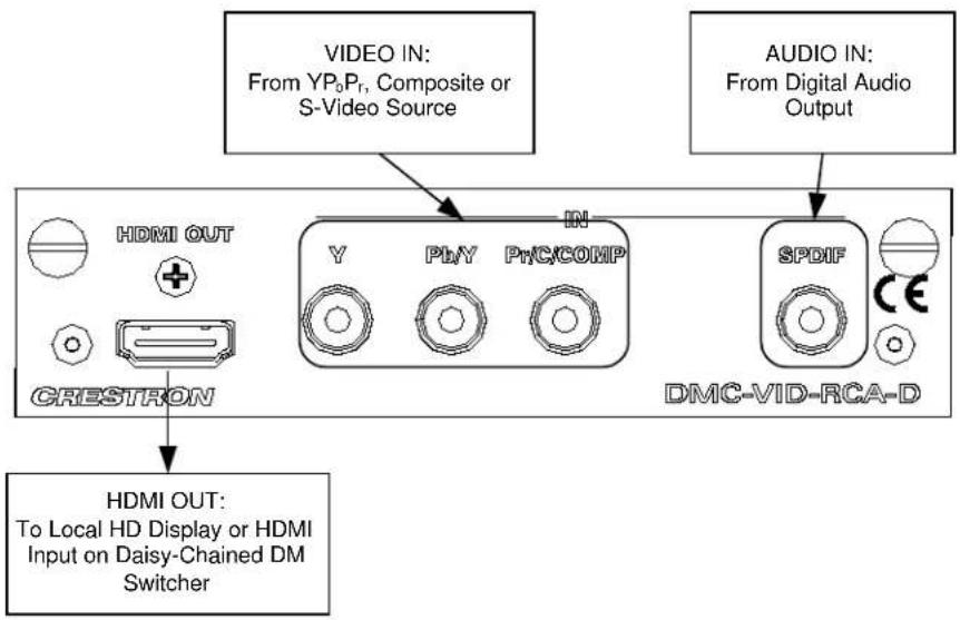
Output Connections
A variety of output configurations are available for the DM switchers. Refer to the following diagrams when making connections to DM output cards.
D & M Ports Using DM Cable
For cards equipped with DM cable connection (RJ-45) refer to the following diagram.
Hardware Hookup for DM Cable Outputs

D & M Ports Using DM Cable (with Optional HDMI Output)
For cards equipped with a DM cable connection (RJ-45) and an HDMI output, refer to the following diagram.
Hardware Hookup for DM Cable Connection with HDMI Output

NOTE: The DM and HDMI ports can be connected simultaneously or individually.
D & M Ports Using DM Fiber
For cards equipped with DM fiber connections refer to the following diagram.
Hardware Hookup for DM Fiber Outputs

flowchart
graph TD
    A["DM: To DM Receiver"] --> B["D"]
    A --> C["M"]
    B --> D["24A B G"]
    C --> E["DMNET: To DM Receiver (Optional)"]
NOTE: When wiring the 24ABG port, connect the 24 and G lines only. Do not connect the A and B lines.
HDMI Outputs
For cards equipped with HDMI outputs refer to the following diagram.
Hardware Hookup for HDMI Outputs
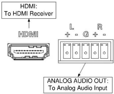
flowchart
graph TD
    A["HDMI: To HDMI Receiver"] --> B["HDMI"]
    B --> C["Analog Audio OUT: To Analog Audio Input"]
    C --> D["L + - G + -"]
    C --> E["R"]
NOTE: The analog audio output will only function if it receives a stereo audio signal from a stereo source or a stereo downmix from a “-DSP” input card.
NOTE: If the audio from a DMC-RCA-D is routed to an HDMI output, audio will not be present on the audio output.
Balanced/unbalanced audio outputs are provided, utilizing five-pin terminal block connectors. For connection details, refer to the following table and diagrams.
Audio Connections
| SIGNAL NAME | BALANCED AUDIO OUTPUT | UNBALANCED AUDIO OUTPUT |
| + L + L + | ||
| - | L - | L – signal return, jumper to GND |
| G Shield/Ground Ground | ||
| + R + R + | ||
| - | R - | R – signal return, jumper to GND |
Typical Balanced/Unbalanced Inputs
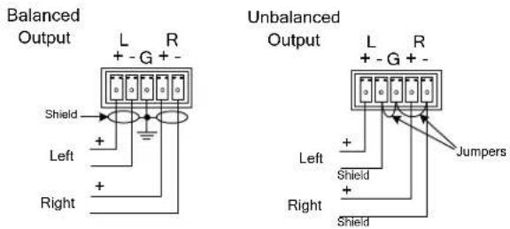
Appendix B: Input Card Configuration
This appendix contains detailed instructions for using the DM switcher's front panel controls to configure DigitalMedia input cards that are installed in a DM switcher.
To view/change the configuration settings for an input card:
- Open the Inputs section of Installer Tools as described on page 42.
- Turn the selection knob to highlight the card to be configured and press the ENTER button.
⇒ For information on configuring the DMC-CAT DM CAT Input Card for DM Switchers, refer to “DMC-CAT” on page 86.
⇒ For information on configuring the DMC-CAT-DSP DM CAT Input Card with DSP for DM Switchers, refer to “DMC-CAT-DSP” on page 94.
⇒ For information on configuring the DMC-DVI DVI/RGB Input Card for DM Switchers, refer to “DMC-DVI” on page 102.
⇒ For information on configuring the DMC-F Fiber Input Card for DM Switchers, refer to “DMC-F” on page 110.
⇒ For information on configuring the DMC-F-DSP Fiber Input Card with DSP for DM Switchers, refer to “DMC-F-DSP” on page 116.
⇒ For information on configuring the DMC-HD HDMI Input Card for DM Switchers, refer to “DMC-HD” on page 122.
⇒ For information on configuring the DMC-HD-DSP HDMI Input Card with DSP for DM Switchers, refer to “DMC-HD-DSP” on page 130.
⇒ For information on configuring the DMC-SDI SDI Input Card for DM Switchers, refer to “DMC-SDI” on page 138.
⇒ For information on configuring the DMC-VID4 Security Camera Input Card for DM Switchers, refer to “DMC-VID4” on page 142.
⇒ For information on configuring the DMC-VID-BNC Analog Video Input Card with Analog Audio for DM Switchers, refer to "DMC-VID-BNC" on page 149.
⇒ For information on configuring the DMC-VID-RCA-A RCA Analog Video Input Card with Analog Audio for DM Switchers, refer to "DMC-VID-RCA-A" on page 156.
⇒ For information on configuring the DMC-VID-RCA-D RCA Analog Video Input Card with Digital Audio for DM Switchers, refer to "DMC-VID-RCA-D" on page 163.
DMC-CAT
The front panel controls for the DMC-CAT allow the user to rename the input, adjust the picture, and view information on the incoming source and the outgoing HDMI signal.
DMC-CAT Controls
3. DMC-CAT Basic DM I
Name: 3
Video Settings
Audio Settings
Using the DMC-CAT controls, the user can:
- Change the input name.
• View details on the video portion of the incoming signal
• View details on the audio portion of the incoming signal.
• View details on the signal delivered to the HDMI OUT (loopback) port. - View details about the device connected to the HDMI OUT (loopback) port.
- Adjust the audio output level
- Select the cable type
• View EDID settings - Perform an HDCP check to determine how many endpoints can be connected to the source
- Restore the default settings.
Name/Rename the Input
To name and/or rename the input:
- Turn the selection knob to highlight Name and press the ENTER button. A cursor will appear next to the current name and controls for changing the name will also be displayed. To cancel and return to the list of options for the input card, press the MENU button.
Edit Input Name
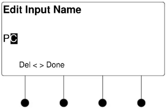
flowchart
graph TD
    A["Edit Input Name"] --> B["PC"]
    B --> C["Del <> Done"]
    C --> D["●"]
    C --> E["●"]
    C --> F["●"]
    C --> G["●"]
- Select letters (upper and lower-case), numbers, or other characters by turning the selection knob until the desired letter, number, or other character is displayed on the LCD. Move the cursor to another position by pressing the soft buttons labeled ◀ and ▶. To delete a character, press the soft button marked Del.
NOTE: The maximum length for any input name is 32 characters.
- After the new name has been entered, press Done to save the name and return to the list of options for the input card.
Video Settings
The DMC-CAT can display information about the video portion of the incoming signal, adjust the picture, and automatically calibrate the source to the display. To view and/or adjust the video settings:
- Turn the selection knob to highlight Video Settings and press the ENTER button.
Video Settings

- Turn the selection knob to view information on input type, video type, resolution, frame rate, and aspect ratio.
- Press the MENU button to return to the list of options for the input card.
Audio Settings
The DMC-CAT can display information about the audio portion of the incoming signal. Available information includes format, frequency, and channels. To view audio settings:
- Turn the selection knob to highlight Audio Settings and press the ENTER button.
Audio Settings
Audio
Format: PCM
Frequency: 48.0kHz
Channels: 2

natural_image
Simple diagram of five black dots suspended by vertical lines (no text or symbols)- Press the MENU button to return to the list of options for the input card.
Loopback Settings
The DMC-CAT can display information about the device connected to the HDMI OUT port as well as information about the signal passed to the HDMI OUT port on the DMC-CAT. Available information includes deep color setting, audio details and EDID information. To view the loopback settings:
- Turn the selection knob to highlight Loopback Settings and press the ENTER button.
Loopback Settings
Loopback Settings
HDCP State: Inactive
Allow Deep Color: On
Deep Color Mode: Off


- Turn the selection knob to view available information, enable/disable deep color, view audio details, or view EDID information.
a. The loopback output can be set to enable or disable the deep color feature of the carried video signal. To enable or disable deep color:
i. Turn the selection knob to highlight Allow Deep Color and press the ENTER button.
Allow Deep Color Mode

ii. The current selection is indicated with an asterisk (*). Turn the selection knob to highlight Off or On and press the ENTER button.
b. To view audio details:
i. Turn the selection knob to highlight Audio and press the ENTER button.
Audio Details
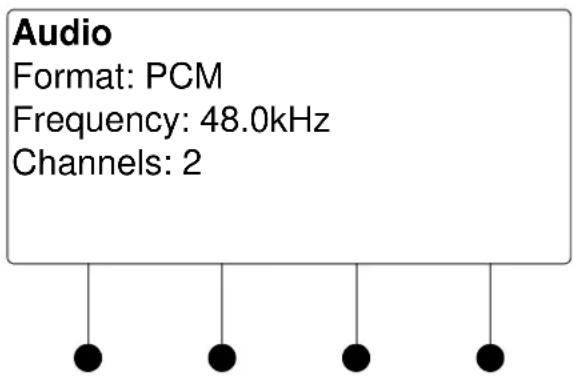
ii. Press the MENU button to return to the Loopback Settings.
c. To view EDID information about the display device connected to the HDMI OUT port:
i. Turn the selection knob to highlight EDID Information and press the ENTER button.
EDID Information
EDID Information
Manufacturer: SHP
Name: SHARP HDMI
Timing: 1920x1080 @ 60Hz

natural_image
Simple diagram of four black dots suspended by vertical lines (no text or symbols)ii. Press the MENU button to return to the Loopback Settings.
- Press the MENU button to return to the list of options for the input card.
Audio Output Level
The output level of the audio signal can be adjusted. To adjust the audio output level:
- Turn the selection knob to highlight Audio Output Level and press the ENTER button.
Audio Output Level

bar
Audio Output Level | Audio Level | Value | | :--- | :--- | | -52 dB | -52 dB |- Turn the selection knob to adjust the audio output level.
- Press the MENU button to return to the list of options for the input card.
DM Cable Type
The card can be configured to use specific types of cables for the DM input signal. To view or select a cable type:
- Turn the selection knob to highlight DM Cable Type and press the ENTER button. The selected cable type is displayed with an asterisk (*).
DM Cable Type
DM Cable Type
* Digital Media Category 6 Category 5e

natural_image
Simple diagram of five black dots suspended by vertical lines (no text or symbols)- To select a different cable type, turn the selection knob to highlight the cable type to be used and press the ENTER button. An asterisk will appear next to the selected cable type.
- Press the MENU button to return to the list of options for the input card.
Show Full EDID
The DMC-CAT can display all EDID data for the source connected to the HDMI IN port. To view EDID information for the connected source:
- Turn the selection knob to highlight Show Full EDID and press the ENTER button.
Show Full EDID
Show Full EDID
Preferred Resolution
Supported Resolutions
Audio Formats

natural_image
Simple diagram of four black dots hanging from a horizontal line, no text or symbols present- Turn the selection knob to highlight the data to be viewed and press the ENTER button.
- Press the MENU button to return to list of available EDID data.
- Press the MENU button to return to the list of options for the input card.
HDCP Check
The switcher can test HDMI sources for switching limitations due to HDCP keys. The number of HDCP keys specify the number of display devices that can be connected to a source over HDMI using HDCP authentication. To run an HDCP check:
- Turn the selection knob to highlight HDCP Check and press the ENTER button.
Confirmation for HDCP Check

Running an HDCP check will disconnect any audio and video routes that are currently set. To proceed with the HDCP check, press the soft button labeled Yes. To cancel the HDCP check, press the soft button labeled No.
Instructions for HDCP Check

- Verify that all source and display devices are powered on. Press the soft button labeled OK to begin the HDCP check. A progress bar will be displayed to show the progress of the HDCP check.
HDCP Check in Progress

When the check is complete the results will be displayed.
HDCP Check Results
HDCP Check Complete
Input 3: (DMC-CAT)
Max devices Allowed: 10
OK
If the number of displays in use exceeds the number of devices supported by the source, an error message will be displayed.
- Press the soft button labeled OK to return to the list of options for the input card.
Restore Defaults
Use the Restore Defaults function to reset the card to its factory settings. The card's factory settings are:
- Loopback Allow Deep Color: On
• Color Space Mode: Force RGB - Enable/Disable input: Input enabled
- Brightness level: 0
- Contrast level: 0
- Saturation level: 0
- Hue level: 0
- Red Level: 0
- Green Level: 0
- Blue Level: 0
- Coarse Phase: 0
- Fine Phase: 0
• X Position: 0 - Y Position 0
To restore the card's default settings:
- Turn the selection knob to highlight Restore Defaults and press the ENTER button.
- Press the soft button labeled Yes to restore the default setting or press the soft button labeled No to cancel and return to the list of options for the input card.
DMC-CAT-DSP
The front panel controls for the DMC-CAT-DSP allow the user to rename the input, adjust the picture, and view information on the incoming source and the outgoing HDMI signal.
DMC-CAT-DSP Controls
3. DMC-CAT-DSP Basic DM
Name: 3
Video Settings
Audio Settings

Using the DMC-CAT-DSP controls, the user can:
- Change the input name.
• View details on the video portion of the incoming signal
• View details on the audio portion of the incoming signal.
• View details on the signal delivered to the HDMI OUT (loopback) port. - View details about the device connected to the HDMI OUT (loopback) port.
- Adjust the audio output level
- Select the cable type
• View EDID settings - Perform an HDCP check to determine how many endpoints can be connected to the source
- Restore the default settings.
Name/Rename the Input
To name and/or rename the input:
- Turn the selection knob to highlight Name and press the ENTER button. A cursor will appear next to the current name and controls for changing the name will also be displayed. To cancel and return to the list of options for the input card, press the MENU button.
Edit Input Name
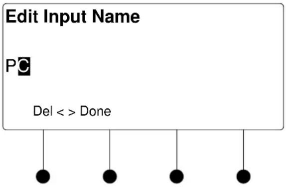
flowchart
graph TD
    A["Edit Input Name"] --> B["PC"]
    B --> C["Del <> Done"]
    C --> D["●"]
    C --> E["●"]
    C --> F["●"]
    C --> G["●"]
- Select letters (upper and lower-case), numbers, or other characters by turning the selection knob until the desired letter, number, or other character is displayed on the LCD. Move the cursor to another position by pressing the soft buttons labeled ◀ and ▶. To delete a character, press the soft button marked Del.
NOTE: The maximum length for any input name is 32 characters.
- After the new name has been entered, press Done to save the name and return to the list of options for the input card.
Video Settings
The DMC-CAT-DSP can display information about the video portion of the incoming signal, adjust the picture, and automatically calibrate the source to the display. To view and/or adjust the video settings:
- Turn the selection knob to highlight Video Settings and press the ENTER button.
Video Settings

- Turn the selection knob to view information on input type, video type, resolution, frame rate, and aspect ratio.
- Press the MENU button to return to the list of options for the input card.
Audio Settings
The DMC-CAT-DSP can display information about the audio portion of the incoming signal. Available information includes format, frequency, and channels. To view audio settings:
- Turn the selection knob to highlight Audio Settings and press the ENTER button.
Audio Settings
Audio
Format: PCM
Frequency: 48.0kHz
Channels: 2

natural_image
Simple diagram of five black dots suspended by vertical lines (no text or symbols)- Press the MENU button to return to the list of options for the input card.
Loopback Settings
The DMC-CAT-DSP can display information about the device connected to the HDMI OUT port as well as information about the signal passed to the HDMI OUT port on the DMC-CAT-DSP. Available information includes deep color setting, audio details and EDID information. To view the loopback settings:
- Turn the selection knob to highlight Loopback Settings and press the ENTER button.
Loopback Settings
Loopback Settings
HDCP State: Inactive
Allow Deep Color: On
Deep Color Mode: Off


- Turn the selection knob to view available information, enable/disable deep color, view audio details, or view EDID information.
a. The loopback output can be set to enable or disable the deep color feature of the carried video signal. To enable or disable deep color:
i. Turn the selection knob to highlight Allow Deep Color and press the ENTER button.
Allow Deep Color Mode
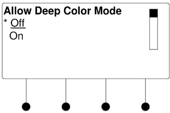
ii. The current selection is indicated with an asterisk (*). Turn the selection knob to highlight Off or On and press the ENTER button.
b. To view audio details:
i. Turn the selection knob to highlight Audio and press the ENTER button.
Audio Details
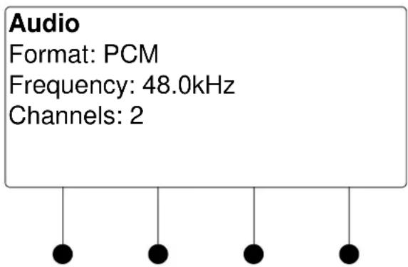
ii. Press the MENU button to return to the Loopback Settings.
c. To view EDID information about the display device connected to the HDMI OUT port:
i. Turn the selection knob to highlight EDID Information and press the ENTER button.
EDID Information
EDID Information
Manufacturer: SHP
Name: SHARP HDMI
Timing: 1920x1080 @ 60Hz

natural_image
Simple diagram of four black dots suspended by vertical lines (no text or symbols)ii. Press the MENU button to return to the Loopback Settings.
- Press the MENU button to return to the list of options for the input card.
Audio Output Level
The output level of the audio signal can be adjusted. To adjust the audio output level:
- Turn the selection knob to highlight Audio Output Level and press the ENTER button.
Audio Output Level

bar
Audio Output Level | Audio Level | Value | | :--- | :--- | | -52 dB | -52 dB |- Turn the selection knob to adjust the audio output level.
- Press the MENU button to return to the list of options for the input card.
DM Cable Type
The card can be configured to use specific types of cables for the DM input signal. To view or select a cable type:
- Turn the selection knob to highlight DM Cable Type and press the ENTER button. The selected cable type is displayed with an asterisk (*).
DM Cable Type
DM Cable Type
* Digital Media Category 6 Category 5e
natural_image
Simple diagram of five black dots suspended by vertical lines (no text or symbols)- To select a different cable type, turn the selection knob to highlight the cable type to be used and press the ENTER button. An asterisk will appear next to the selected cable type.
- Press the MENU button to return to the list of options for the input card.
Show Full EDID
The DMC-CAT-DSP can display all EDID data for the source connected to the HDMI IN port. To view EDID information for the connected source:
- Turn the selection knob to highlight Show Full EDID and press the ENTER button.
Show Full EDID
Show Full EDID
Preferred Resolution
Supported Resolutions
Audio Formats

natural_image
Simple diagram of four black dots hanging from a horizontal line, no text or symbols present- Turn the selection knob to highlight the data to be viewed and press the ENTER button.
- Press the MENU button to return to list of available EDID data.
- Press the MENU button to return to the list of options for the input card.
HDCP Check
The switcher can test HDMI sources for switching limitations due to HDCP keys. The number of HDCP keys specify the number of display devices that can be connected to a source over HDMI using HDCP authentication. To run an HDCP check:
- Turn the selection knob to highlight HDCP Check and press the ENTER button.
Confirmation for HDCP Check

Running an HDCP check will disconnect any audio and video routes that are currently set. To proceed with the HDCP check, press the soft button labeled Yes. To cancel the HDCP check, press the soft button labeled No.
Instructions for HDCP Check

- Verify that all source and display devices are powered on. Press the soft button labeled OK to begin the HDCP check. A progress bar will be displayed to show the progress of the HDCP check.
HDCP Check in Progress

When the check is complete the results will be displayed.
HDCP Check Results
HDCP Check Complete Input 3: (DMC-CAT-DSP) Max devices Allowed: 10
OK
If the number of displays in use exceeds the number of devices supported by the source, an error message will be displayed.
- Press the soft button labeled OK to return to the list of options for the input card.
Restore Defaults
Use the Restore Defaults function to reset the card to its factory settings. The card's factory settings are:
- Loopback Allow Deep Color: On
• Color Space Mode: Force RGB - Enable/Disable input: Input enabled
- Brightness level: 0
- Contrast level: 0
- Saturation level: 0
- Hue level: 0
- Red Level: 0
- Green Level: 0
- Blue Level: 0
- Coarse Phase: 0
- Fine Phase: 0
• X Position: 0 - Y Position 0
To restore the card's default settings:
- Turn the selection knob to highlight Restore Defaults and press the ENTER button.
- Press the soft button labeled Yes to restore the default setting or press the soft button labeled No to cancel and return to the list of options for the input card.
DMC-DVI
The front panel controls for the DMC-DVI allow the user to rename the input, adjust the picture, and view information on the incoming component video source and the outgoing HDMI signal.
DMC-DVI Controls

Using the DMC-DVI controls, the user can:
- Change the input name.
• View details on the video portion of the incoming signal
• View details on the audio portion of the incoming signal.
• View details on the signal delivered to the HDMI OUT (loopback) port. - View details about the device connected to the HDMI OUT (loopback) port.
- Perform an HDCP check to determine how many endpoints can be connected to the source
- Restore the default settings.
Name/Rename the Input
To name and/or rename the input:
- Turn the selection knob to highlight Name and press the ENTER button. A cursor will appear next to the current name and controls for changing the name will also be displayed. To cancel and return to the list of options for the input card, press the MENU button.
Edit Input Name

flowchart
graph TD
    A["Edit Input Name"] --> B["Process"]
    B --> C["Del <>"]
    B --> D["Done"]
- Select letters (upper and lower-case), numbers, or other characters by turning the selection knob until the desired letter, number, or other character is displayed on the LCD. Move the cursor to another position by pressing the soft buttons labeled ◀ and ▶. To delete a character, press the soft button marked Del.
NOTE: The maximum length for any input name is 32 characters.
- After the new name has been entered, press Done to save the name and return to the list of options for the input card.
Video Settings
The DMC-DVI can display information about the video portion of the incoming signal, adjust the picture, and automatically calibrate the source to the display. To view and/or adjust the video settings:
- Turn the selection knob to highlight Video Settings and press the ENTER button.
Video Settings
Video Settings
Video Type: Interlaced
Resolution: 1920x1080
Frame Rate: 30 fps
natural_image
Simple diagram of four black dots suspended by vertical lines (no text or symbols)- Turn the selection knob to view information on input type, video type, resolution, frame rate, and aspect ratio.
- The picture settings can also be adjusted.
Picture controls can be used to adjust the picture's brightness, contrast, saturation, and hue levels. To adjust the picture:
a. Turn the selection knob to highlight Picture Controls and press the ENTER button.
b. Turn the selection knob to highlight the picture control to be adjusted and press the ENTER button. Controls are available for brightness, contrast, saturation, and hue.
Brightness Control

Contrast Control
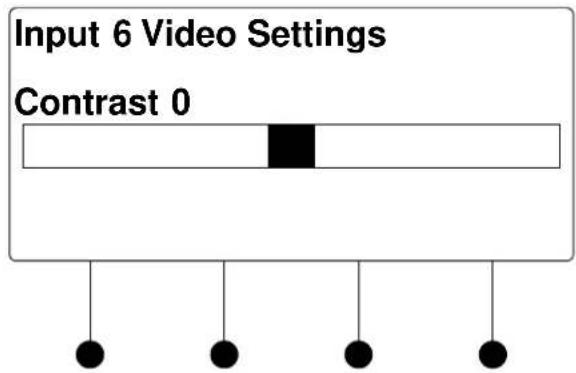
Saturation Control
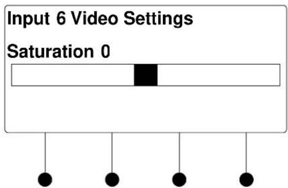
Hue Control

c. Turn the selection knob to display the desired level and press the ENTER button to save the setting and return to the list of picture controls.
d. Press the MENU button to return to the list of options for video settings.
- Use the Auto-Calibrate function to resize the image and maximize use of the available screen size. To use the Auto-Calibrate function, turn the selection knob to highlight Auto-Calibrate and press the ENTER button.
- Press the MENU button to return to the list of options for the input card.
Audio Settings
The DMC-DVI can display information about the audio portion of the incoming signal. Available information includes format, frequency, and channels. To view audio settings:
- Turn the selection knob to highlight Audio Settings and press the ENTER button.
Audio Settings
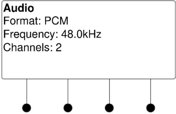
- Press the MENU button to return to the list of options for the input card.
Loopback Settings
The DMC-DVI can display information about the device connected to the HDMI OUT port as well as information about the signal passed to the HDMI OUT port on the DMC-DVI. Available information includes deep color setting, audio details and EDID information. To view the loopback settings:
- Turn the selection knob to highlight Loopback Settings and press the ENTER button.
Loopback Settings
Loopback Settings HDCP State: Inactive Allow Deep Color: On Deep Color Mode: Off

- Turn the selection knob to view available information, enable/disable deep color, view audio details, or view EDID information.
a. The loopback output can be set to enable or disable the deep color feature of the carried video signal. To enable or disable deep color:
i. Turn the selection knob to highlight Allow Deep Color and press the ENTER button.
Allow Deep Color Mode

ii. The current selection is indicated with an asterisk (*). Turn the selection knob to highlight Off or On and press the ENTER button.
b. To view audio details:
i. Turn the selection knob to highlight Audio and press the ENTER button.
Audio Details
Audio
Format: PCM
Frequency: 48.0kHz
Channels: 2
ii. Press the MENU button to return to the Loopback Settings.
c. To view EDID information about the display device connected to the HDMI OUT port:
i. Turn the selection knob to highlight EDID Information and press the ENTER button.
EDID Information
EDID Information
Manufacturer: SHP
Name: SHARP HDMI
Timing: 1920x1080 @ 60Hz
ii. Press the MENU button to return to the Loopback Settings.
- Press the MENU button to return to the list of options for the input card.
HDCP Check
The switcher can test DVI sources for switching limitations due to HDCP keys. The number of HDCP keys specify the number of display devices that can be connected to a source over DVI using HDCP authentication. To run an HDCP check:
- Turn the selection knob to highlight HDCP Check and press the ENTER button.
Confirmation for HDCP Check

Running an HDCP check will disconnect any audio and video routes that are currently set. To proceed with the HDCP check, press the soft button labeled Yes. To cancel the HDCP check, press the soft button labeled No.
Instructions for HDCP Check
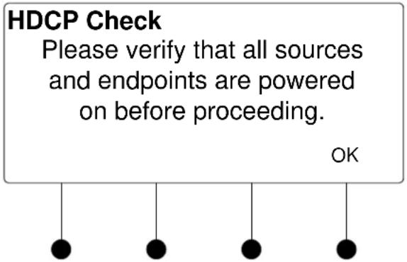
- Verify that all source and display devices are powered on. Press the soft button labeled OK to begin the HDCP check. A progress bar will be displayed to show the progress of the HDCP check.
HDCP Check in Progress

When the check is complete the results will be displayed.
HDCP Check Results
HDCP Check Complete
Input 3: (DMC-DVI)
Max devices Allowed: 10
OK
If the number of displays in use exceeds the number of devices supported by the source, an error message will be displayed.
- Press the soft button labeled OK to return to the list of options for the input card.
Restore Defaults
Use the Restore Defaults function to reset the card to its factory settings. The card's factory settings are:
- Loopback Allow Deep Color: On
• Color Space Mode: Force RGB - Enable/Disable input: Input enabled
- Brightness level: 0
- Contrast level: 0
- Saturation level: 0
- Hue level: 0
- Red Level: 0
- Green Level: 0
- Blue Level: 0
- Coarse Phase: 0
- Fine Phase: 0
• X Position: 0 - Y Position 0
To restore the card's default settings:
- Turn the selection knob to highlight Restore Defaults and press the ENTER button.
- Press the soft button labeled Yes to restore the default setting or press the soft button labeled No to cancel and return to the list of options for the input card.
DMC-F
The front panel controls for the DMC-F allow the user to rename the input, adjust the picture, and view information on the incoming component video source and the outgoing HDMI signal.
DMC-F Controls
3. DMC-F Basic Fiber In
Name: 3
Video Settings
Audio Settings
Using the DMC-F controls, the user can:
- Change the input name.
• View details on the video portion of the incoming signal
• View details on the audio portion of the incoming signal.
• View details on the signal delivered to the HDMI OUT (loopback) port. - View details about the device connected to the HDMI OUT (loopback) port.
- Adjust the audio output level
• View EDID settings - Restore the default settings.
Name/Rename the Input
To name and/or rename the input:
- Turn the selection knob to highlight Name and press the ENTER button. A cursor will appear next to the current name and controls for changing the name will also be displayed. To cancel and return to the list of options for the input card, press the MENU button.
Edit Input Name
Edit Input Name
DM Transmitter
Del
<> Done


- Select letters (upper and lower-case), numbers, or other characters by turning the selection knob until the desired letter, number, or other character is displayed on the LCD. Move the cursor to another position by pressing the soft buttons labeled ◀ and ▶. To delete a character, press the soft button marked Del.
NOTE: The maximum length for any input name is 32 characters.
- After the new name has been entered, press Done to save the name and return to the list of options for the input card.
Video Settings
The DMC-F can display information about the video portion of the incoming signal, adjust the picture, and automatically calibrate the source to the display. To view and/or adjust the video settings:
- Turn the selection knob to highlight Video Settings and press the ENTER button.
Video Settings
Video Settings
Input Type: HDMI
Video Type: Interlaced
Resolution: 1920x1080


natural_image
Simple diagram of four black dots suspended by vertical lines (no text or symbols)- Turn the selection knob to view information on input type, video type, resolution, frame rate, and aspect ratio.
- Press the MENU button to return to the list of options for the input card.
Audio Settings
The DMC-F can display information about the audio portion of the incoming signal. Available information includes format, frequency, and channels. To view audio settings:
- Turn the selection knob to highlight Audio Settings and press the ENTER button.
Audio Settings
Audio
Format: PCM
Frequency: 48.0kHz
Channels: 2

natural_image
Simple diagram of four black dots suspended by vertical lines (no text or symbols)- Press the MENU button to return to the list of options for the input card.
Loopback Settings
The DMC-F can display information about the device connected to the HDMI OUT port as well as information about the signal passed to the HDMI OUT port on the DMC-F. Available information includes deep color setting, audio details and EDID information. To view the loopback settings:
- Turn the selection knob to highlight Loopback Settings and press the ENTER button.
Loopback Settings

- Turn the selection knob to view available information, enable/disable deep color, view audio details, or view EDID information.
a. The loopback output can be set to enable or disable the deep color feature of the carried video signal. To enable or disable deep color: i. Turn the selection knob to highlight Allow Deep Color and press the ENTER button.
Allow Deep Color Mode

ii. The current selection is indicated with an asterisk (*). Turn the selection knob to highlight Off or On and press the ENTER button.
b. To view audio details:
i. Turn the selection knob to highlight Audio and press the ENTER button.
Audio Details
Audio
Format: PCM
Frequency: 48.0kHz
Channels: 2
ii. Press the MENU button to return to the Loopback Settings.
c. To view EDID information about the display device connected to the HDMI OUT port:
i. Turn the selection knob to highlight EDID Information and press the ENTER button.
EDID Information
EDID Information
Manufacturer: SHP
Name: SHARP HDMI
Timing: 1920x1080 @ 60Hz
ii. Press the MENU button to return to the Loopback Settings.
- Press the MENU button to return to the list of options for the input card.
The output level of the audio signal can be adjusted. To adjust the audio output level:
- Turn the selection knob to highlight Audio Output Level and press the ENTER button.
Audio Output Level
Audio Output Level

bar
Audio Output Level | Audio Level | Audio Output Level (dB) | | :--- | :--- | | 1 | -52 | | 2 | -52 | | 3 | -52 | | 4 | -52 | | 5 | -52 |- Turn the selection knob to adjust the audio output level.
- Press the MENU button to return to the list of options for the input card.
Show Full EDID
The DMC-F can display all EDID data for the source connected to the HDMI IN port. To view EDID information for the connected source:
- Turn the selection knob to highlight Show Full EDID and press the ENTER button.
Show Full EDID
Show Full EDID
Preferred Resolution
Supported Resolutions
Audio Formats

natural_image
Simple diagram of four black dots suspended by strings (no text or symbols)- Turn the selection knob to highlight the data to be viewed and press the ENTER button.
- Press the MENU button to return to list of available EDID data.
- Press the MENU button to return to the list of options for the input card.
Restore Defaults
Use the Restore Defaults function to reset the card to its factory settings. The card's factory settings are:
- Loopback Allow Deep Color: On
• Color Space Mode: Force RGB - Enable/Disable input: Input enabled
- Brightness level: 0
- Contrast level: 0
• Saturation level: 0 -
Hue level: 0
-
Red Level: 0
- Green Level: 0
- Blue Level: 0
- Coarse Phase: 0
- Fine Phase: 0
• X Position: 0 - Y Position 0
To restore the card's default settings:
- Turn the selection knob to highlight Restore Defaults and press the ENTER button.
- Press the soft button labeled Yes to restore the default setting or press the soft button labeled No to cancel and return to the list of options for the input card.
DMC-F-DSP
The front panel controls for the DMC-F-DSP allow the user to rename the input, adjust the picture, and view information on the incoming component video source and the outgoing HDMI signal.
DMC-F-DSP Controls
3. DMC-F Basic Fiber In
Name: 3
Video Settings
Audio Settings
Using the DMC-F-DSP controls, the user can:
- Change the input name.
• View details on the video portion of the incoming signal
• View details on the audio portion of the incoming signal.
• View details on the signal delivered to the HDMI OUT (loopback) port.
- View details about the device connected to the HDMI OUT (loopback) port.
- Adjust the audio output level
• View EDID settings - Restore the default settings.
Name/Rename the Input
To name and/or rename the input:
- Turn the selection knob to highlight Name and press the ENTER button. A cursor will appear next to the current name and controls for changing the name will also be displayed. To cancel and return to the list of options for the input card, press the MENU button.
Edit Input Name
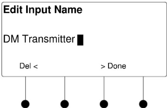
flowchart
graph TD
    A["Edit Input Name"] --> B["DM Transmitter"]
    B --> C["Del <"]
    B --> D["> Done"]
    C --> E["●"]
    D --> F["●"]
    E --> G["●"]
    F --> H["●"]
- Select letters (upper and lower-case), numbers, or other characters by turning the selection knob until the desired letter, number, or other character is displayed on the LCD. Move the cursor to another position by pressing the soft buttons labeled ◀ and ▶. To delete a character, press the soft button marked Del.
NOTE: The maximum length for any input name is 32 characters.
- After the new name has been entered, press Done to save the name and return to the list of options for the input card.
Video Settings
The DMC-F-DSP can display information about the video portion of the incoming signal, adjust the picture, and automatically calibrate the source to the display. To view and/or adjust the video settings:
- Turn the selection knob to highlight Video Settings and press the ENTER button.
Video Settings
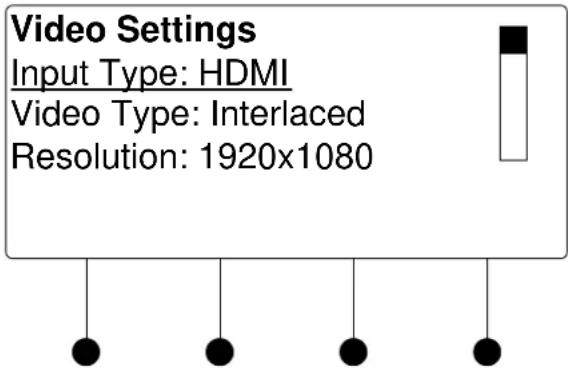
- Turn the selection knob to view information on input type, video type, resolution, frame rate, and aspect ratio.
- Press the MENU button to return to the list of options for the input card.
Audio Settings
The DMC-F-DSP can display information about the audio portion of the incoming signal. Available information includes format, frequency, and channels. To view audio settings:
- Turn the selection knob to highlight Audio Settings and press the ENTER button.
Audio Settings
Audio
Format: PCM
Frequency: 48.0kHz
Channels: 2

natural_image
Simple diagram of five black dots suspended by vertical lines (no text or symbols)- Press the MENU button to return to the list of options for the input card.
Loopback Settings
The DMC-F-DSP can display information about the device connected to the HDMI OUT port as well as information about the signal passed to the HDMI OUT port on the DMC-F-DSP. Available information includes deep color setting, audio details and EDID information. To view the loopback settings:
- Turn the selection knob to highlight Loopback Settings and press the ENTER button.
Loopback Settings
Loopback Settings
HDCP State: Inactive
Allow Deep Color: On
Deep Color Mode: Off

- Turn the selection knob to view available information, enable/disable deep color, view audio details, or view EDID information.
a. The loopback output can be set to enable or disable the deep color feature of the carried video signal. To enable or disable deep color:
i. Turn the selection knob to highlight Allow Deep Color and press the ENTER button.
Allow Deep Color Mode
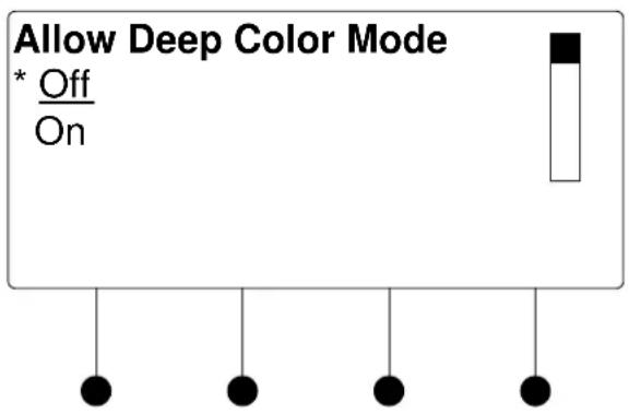
ii. The current selection is indicated with an asterisk (*). Turn the selection knob to highlight Off or On and press the ENTER button.
b. To view audio details:
i. Turn the selection knob to highlight Audio and press the ENTER button.
Audio Details
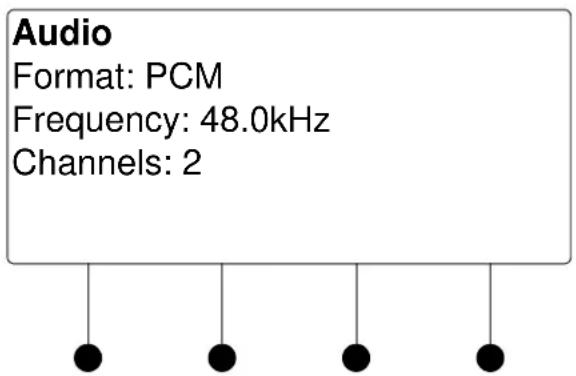
ii. Press the MENU button to return to the Loopback Settings.
c. To view EDID information about the display device connected to the HDMI OUT port:
i. Turn the selection knob to highlight EDID Information and press the ENTER button.
EDID Information
EDID Information
Manufacturer: SHP
Name: SHARP HDMI
Timing: 1920x1080 @ 60Hz
natural_image
Simple diagram of four black dots suspended by vertical lines (no text or symbols)ii. Press the MENU button to return to the Loopback Settings.
- Press the MENU button to return to the list of options for the input card.
Audio Output Level
The output level of the audio signal can be adjusted. To adjust the audio output level:
- Turn the selection knob to highlight Audio Output Level and press the ENTER button.
Audio Output Level

bar
Audio Output Level | Audio Level | Value | | :--- | :--- | | -52 dB | -52 dB |- Turn the selection knob to adjust the audio output level.
- Press the MENU button to return to the list of options for the input card.
The DMC-F-DSP can display all EDID data for the source connected to the HDMI IN port. To view EDID information for the connected source:
- Turn the selection knob to highlight Show Full EDID and press the ENTER button.
Show Full EDID
Show Full EDID
Show Full EDID Preferred Resolution Supported Resolutions Audio Formats
- Turn the selection knob to highlight the data to be viewed and press the ENTER button.
- Press the MENU button to return to list of available EDID data.
- Press the MENU button to return to the list of options for the input card.
Restore Defaults
Use the Restore Defaults function to reset the card to its factory settings. The card's factory settings are:
- Loopback Allow Deep Color: On
• Color Space Mode: Force RGB - Enable/Disable input: Input enabled
- Brightness level: 0
- Contrast level: 0
- Saturation level: 0
- Hue level: 0
- Red Level: 0
- Green Level: 0
- Blue Level: 0
- Coarse Phase: 0
- Fine Phase: 0
• X Position: 0 - Y Position 0
To restore the card's default settings:
- Turn the selection knob to highlight Restore Defaults and press the ENTER button.
- Press the soft button labeled Yes to restore the default setting or press the soft button labeled No to cancel and return to the list of options for the input card.
DMC-HD
The front panel controls for the DMC-HD allow the user to rename the input and view information on the incoming HDMI source and the outgoing HDMI signal.
DMC-HD Controls
3. DMC-HD HDMI
Name: 3 Video Settings Audio Settings

Using the DMC-HD controls, the user can:
- Change the input name.
• View details on the video portion of the incoming signal
• View details on the audio portion of the incoming signal.
• View details on the signal delivered to the HDMI OUT (loopback) port. - View details about the device connected to the HDMI OUT (loopback) port.
- Adjust the audio output level.
• View EDID settings. - Perform an HDCP check to determine how many endpoints can be connected to the source.
- Restore the default settings.
Name/Rename the Input
To name and/or rename the input:
- Turn the selection knob to highlight Name and press the ENTER button. A cursor will appear next to the current name and controls for changing the name will also be displayed. To cancel and return to the list of options for the input card, press the MENU button.
Edit Input Name
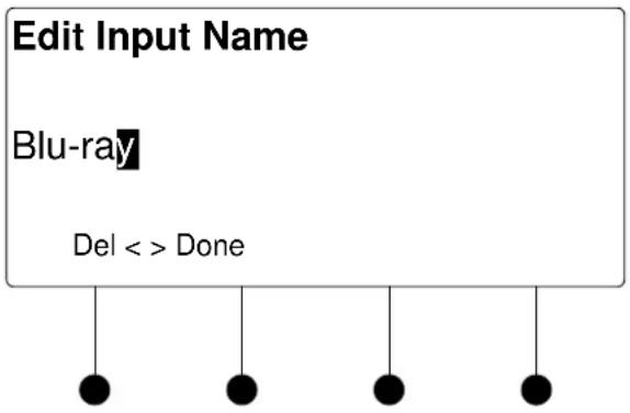
- Select letters (upper and lower-case), numbers, or other characters by turning the selection knob until the desired letter, number, or other character is displayed on the LCD. Move the cursor to another position by pressing the soft buttons labeled ◀ and ▶. To delete a character, press the soft button marked Del.
NOTE: The maximum length for any input name is 32 characters.
- After the new name has been entered, press Done to save the name and return to the list of options for the input card.
Video Settings
The DMC-HD can display information about the video portion of the incoming signal. Available information includes video type, resolution, frame rate, aspect ratio, deep color setting, HDCP state, and the maximum amount of downstream devices. To view video settings:
- Turn the selection knob to highlight Video Settings and press the ENTER button.
Video Settings

- Turn the selection knob to view the available information.
- Press the MENU button to return to the list of options for the input card.
Audio Settings
The DMC-HD can display information about the audio portion of the incoming signal. Available information includes format, frequency, and channels. To view audio settings:
- Turn the selection knob to highlight Audio Settings and press the ENTER button.
Audio Settings
Audio
Format: PCM
Frequency: 48.0kHz
Channels: 2
natural_image
Simple diagram of five black dots suspended by vertical lines (no text or symbols)- Press the MENU button to return to the list of options for the input card.
Loopback Settings
The DMC-HD can display information about the device connected to the HDMI OUT port as well as information about the signal passed to the HDMI OUT port on the DMC-HD. Available information includes HDCP state, deep color setting, audio details and EDID information. To view the loopback settings:
- Turn the selection knob to highlight Loopback Settings and press the ENTER button.
Loopback Settings
Loopback Settings
HDCP State: Inactive
Allow Deep Color: On
Deep Color Mode: Off

- Turn the selection knob to view available information, enable/disable deep color, view audio details, or view EDID information.
a. The loopback output can be set to enable or disable the deep color feature of the carried video signal. To enable or disable deep color:
i. Turn the selection knob to highlight Allow Deep Color and press the ENTER button.
Allow Deep Color Mode

ii. The current selection is indicated with an asterisk (*). Turn the selection knob to highlight Off or On and press the ENTER button.
b. To view audio details:
i. Turn the selection knob to highlight Audio and press the ENTER button.
Audio Details

ii. Press the MENU button to return to the Loopback Settings.
c. To view EDID information about the display device connected to the HDMI OUT port:
i. Turn the selection knob to highlight EDID Information and press the ENTER button.
EDID Information
EDID Information
Manufacturer: SHP
Name: SHARP HDMI
Timing: 1920x1080 @ 60Hz

natural_image
Simple diagram of four black dots suspended by vertical lines (no text or symbols)ii. Press the MENU button to return to the Loopback Settings.
- Press the MENU button to return to the list of options for the input card.
Audio Output Level
The output level of the audio signal can be adjusted. To adjust the audio output level:
- Turn the selection knob to highlight Audio Output Level and press the ENTER button.
Audio Output Level
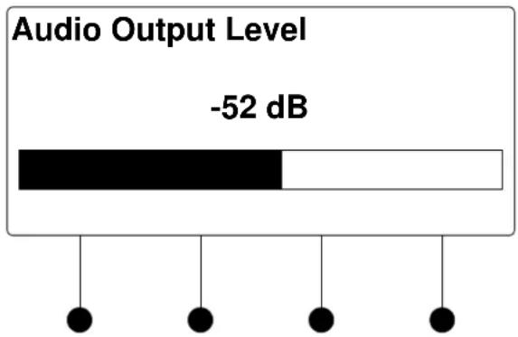
bar
Audio Output Level | Audio Output Level | Value (dB) | | :--- | :--- | | Black Bar | -52 | | White Bar | 0 | The bottom of the bars is filled with black dots, which are all equal to zero. This indicates a fixed level of audio output at -52 dB.- Turn the selection knob to adjust the audio output level.
- Press the MENU button to return to the list of options for the input card.
Show Full EDID
The DMC-HD can display all EDID data for the source connected to the HDMI IN port. To view EDID information for the connected source:
- Turn the selection knob to highlight Show Full EDID and press the ENTER button.
Show Full EDID
Show Full EDID
Preferred Resolution
Supported Resolutions
Audio Formats
natural_image
Simple diagram of five black dots suspended by vertical lines (no text or symbols)- Turn the selection knob to highlight the data to be viewed and press the ENTER button.
- Press the MENU button to return to list of available EDID data.
- Press the MENU button to return to the list of options for the input card.
HDCP Check
The switcher can test HDMI sources for switching limitations due to HDCP keys. The number of HDCP keys specify the number of display devices that can be connected to a source over HDMI using HDCP authentication. To run an HDCP check:
- Turn the selection knob to highlight HDCP Check and press the ENTER button.
Confirmation for HDCP Check
HDCP Check The HDCP check will result in all current routes being cleared. Continue? No Yes
Running an HDCP check will disconnect any audio and video routes that are currently set. To proceed with the HDCP check, press the soft button labeled Yes. To cancel the HDCP check, press the soft button labeled No.
Instructions for HDCP Check

- Verify that all source and display devices are powered on. Press the soft button labeled OK to begin the HDCP check. A progress bar will be displayed to show the progress of the HDCP check.
HDCP Check in Progress

When the check is complete the results will be displayed.
HDCP Check Results
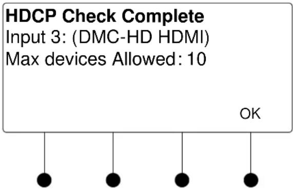
If the number of displays in use exceeds the number of devices supported by the source, an error message will be displayed.
- Press the soft button labeled OK to return to the list of options for the input card.
Restore Defaults
Use the Restore Defaults function to reset the card to its factory settings. The card's factory settings are:
- Loopback Allow Deep Color: On
• EDID Mode: Best Common
• Max Input Resolution: 165
• Video EDID Group: 65535
• Audio EDID Group: 65535 - Copy Sink EDID: 1
• Color Space Mode: Force RGB
• Max Output 1 Pixel Rate: 225 - Max Devices: 16
- Input: Enabled
• Stream Name: 1-16 (based on which stream)
To restore the card's default settings:
- Turn the selection knob to highlight Restore Defaults and press the ENTER button.
- Press the soft button labeled Yes to restore the default setting or press the soft button labeled No to cancel and return to the list of options for the input card.
DMC-HD-DSP
The front panel controls for the DMC-HD-DSP allow the user to rename the input and view information on the incoming HDMI source and the outgoing HDMI signal.
DMC-HD-DSP Controls
3. DMC-HD-DSP Advanc
Name: 3
Video Settings
Audio Settings
Using the DMC-HD-DSP controls, the user can:
- Change the input name.
• View details on the video portion of the incoming signal
• View details on the audio portion of the incoming signal.
• View details on the signal delivered to the HDMI OUT (loopback) port. - View details about the device connected to the HDMI OUT (loopback) port.
- Adjust the audio output level.
• View EDID settings. - Perform an HDCP check to determine how many endpoints can be connected to the source.
- Restore the default settings.
Name/Rename the Input
To name and/or rename the input:
- Turn the selection knob to highlight Name and press the ENTER button. A cursor will appear next to the current name and controls for changing the name will also be displayed. To cancel and return to the list of options for the input card, press the MENU button.
Edit Input Name

- Select letters (upper and lower-case), numbers, or other characters by turning the selection knob until the desired letter, number, or other character is displayed on the LCD. Move the cursor to another position by pressing the soft buttons labeled ◀ and ▶. To delete a character, press the soft button marked Del.
NOTE: The maximum length for any input name is 32 characters.
- After the new name has been entered, press Done to save the name and return to the list of options for the input card.
Video Settings
The DMC-HD-DSP can display information about the video portion of the incoming signal. Available information includes video type, resolution, frame rate, aspect ratio, deep color setting, HDCP state, and the maximum amount of downstream devices. To view video settings:
- Turn the selection knob to highlight Video Settings and press the ENTER button.
Video Settings

- Turn the selection knob to view the available information.
- Press the MENU button to return to the list of options for the input card.
Audio Settings
The DMC-HD-DSP can display information about the audio portion of the incoming signal. Available information includes format, frequency, and channels. To view audio settings:
- Turn the selection knob to highlight Audio Settings and press the ENTER button.
Audio Settings
Audio
Format: PCM
Frequency: 48.0kHz
Channels: 2

natural_image
Simple diagram of five black dots suspended by vertical lines (no text or symbols)- Press the MENU button to return to the list of options for the input card.
Loopback Settings
The DMC-HD-DSP can display information about the device connected to the HDMI OUT port as well as information about the signal passed to the HDMI OUT port on the DMC-HD-DSP. Available information includes HDCP state, deep color setting, audio details and EDID information. To view the loopback settings:
- Turn the selection knob to highlight Loopback Settings and press the ENTER button.
Loopback Settings
Loopback Settings
HDCP State: Inactive
Allow Deep Color: On
Deep Color Mode: Off


- Turn the selection knob to view available information, enable/disable deep color, view audio details, or view EDID information.
a. The loopback output can be set to enable or disable the deep color feature of the carried video signal. To enable or disable deep color:
i. Turn the selection knob to highlight Allow Deep Color and press the ENTER button.
Allow Deep Color Mode

ii. The current selection is indicated with an asterisk (*). Turn the selection knob to highlight Off or On and press the ENTER button.
b. To view audio details:
i. Turn the selection knob to highlight Audio and press the ENTER button.
Audio Details

ii. Press the MENU button to return to the Loopback Settings.
c. To view EDID information about the display device connected to the HDMI OUT port:
i. Turn the selection knob to highlight EDID Information and press the ENTER button.
EDID Information
EDID Information
Manufacturer: SHP
Name: SHARP HDMI
Timing: 1920x1080 @ 60Hz

natural_image
Simple diagram of four black dots suspended by vertical lines (no text or symbols)ii. Press the MENU button to return to the Loopback Settings.
- Press the MENU button to return to the list of options for the input card.
Audio Output Level
The output level of the audio signal can be adjusted. To adjust the audio output level:
- Turn the selection knob to highlight Audio Output Level and press the ENTER button.
Audio Output Level
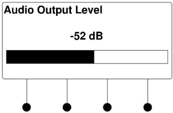
bar
Audio Output Level | Audio Level | Value | | :--- | :--- | | -52 dB | -52 dB |- Turn the selection knob to adjust the audio output level.
- Press the MENU button to return to the list of options for the input card.
Show Full EDID
The DMC-HD-DSP can display all EDID data for the source connected to the HDMI IN port. To view EDID information for the connected source:
- Turn the selection knob to highlight Show Full EDID and press the ENTER button.
Show Full EDID
Show Full EDID
Preferred Resolution
Supported Resolutions
Audio Formats
natural_image
Simple diagram of five black dots suspended by vertical lines (no text or symbols)- Turn the selection knob to highlight the data to be viewed and press the ENTER button.
- Press the MENU button to return to list of available EDID data.
- Press the MENU button to return to the list of options for the input card.
HDCP Check
The switcher can test HDMI sources for switching limitations due to HDCP keys. The number of HDCP keys specify the number of display devices that can be connected to a source over HDMI using HDCP authentication. To run an HDCP check:
- Turn the selection knob to highlight HDCP Check and press the ENTER button.
Confirmation for HDCP Check
HDCP Check The HDCP check will result in all current routes being cleared. Continue? No Yes
Running an HDCP check will disconnect any audio and video routes that are currently set. To proceed with the HDCP check, press the soft button labeled Yes. To cancel the HDCP check, press the soft button labeled No.
Instructions for HDCP Check

- Verify that all source and display devices are powered on. Press the soft button labeled OK to begin the HDCP check. A progress bar will be displayed to show the progress of the HDCP check.
HDCP Check in Progress
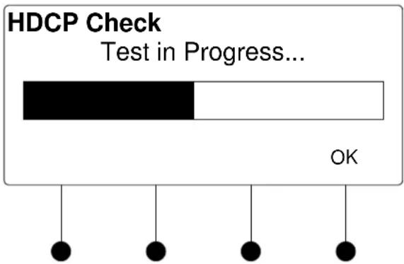
When the check is complete the results will be displayed.
HDCP Check Results

If the number of displays in use exceeds the number of devices supported by the source, an error message will be displayed.
- Press the soft button labeled OK to return to the list of options for the input card.
Restore Defaults
Use the Restore Defaults function to reset the card to its factory settings. The card's factory settings are:
- Loopback Allow Deep Color: On
• EDID Mode: Best Common
• Max Input Resolution: 165
• Video EDID Group: 65535
• Audio EDID Group: 65535 - Copy Sink EDID: 1
• Color Space Mode: 0 (Force RGB)
• Max Output 1 Pixel Rate: 225 - Max Devices: 16
- Input: Enabled
• Stream Name: 1-16 (based on which stream)
To restore the card's default settings:
- Turn the selection knob to highlight Restore Defaults and press the ENTER button.
- Press the soft button labeled Yes to restore the default setting or press the soft button labeled No to cancel and return to the list of options for the input card.
DMC-SDI
The front panel controls for the DMC-SDI allow the user to rename the input, adjust the picture, and view information on the incoming SDI source and the outgoing HDMI signal.
DMC-SDI Controls

Using the DMC-SDI controls, the user can:
- Change the input name.
• View details on the video portion of the incoming signal
• View details on the audio portion of the incoming signal.
• View details on the signal delivered to the HDMI OUT (loopback) port. - View details about the device connected to the HDMI OUT (loopback) port.
- Adjust the audio output level
- Restore the default settings.
Name/Rename the Input
To name and/or rename the input:
- Turn the selection knob to highlight Name and press the ENTER button. A cursor will appear next to the current name and controls for changing the name will also be displayed. To cancel and return to the list of options for the input card, press the MENU button.
Edit Input Name

flowchart
graph TD
    A["Edit Input Name"] --> B["DVD"]
    B --> C["Del <"]
    B --> D["> Done"]
- Select letters (upper and lower-case), numbers, or other characters by turning the selection knob until the desired letter, number, or other character is displayed on the LCD. Move the cursor to another position by pressing the soft buttons labeled ◀ and ▶. To delete a character, press the soft button marked Del.
NOTE: The maximum length for any input name is 32 characters.
- After the new name has been entered, press Done to save the name and return to the list of options for the input card.
Video Settings
The DMC-SDI can display information about the video portion of the incoming signal. To view the video settings:
- Turn the selection knob to highlight Video Settings and press the ENTER button.
Video Settings
Video Settings
Input Type: SDI
Video Type: Interlaced
Resolution: 1920x1080

Audio Settings
- Turn the selection knob to view information on input type, video type, resolution, frame rate, and aspect ratio.
- Press the MENU button to return to the list of options for the input card.
The DMC-SDI can display information about the audio portion of the incoming signal. Available information includes format, frequency, and channels. To view audio settings:
- Turn the selection knob to highlight Audio Settings and press the ENTER button.
Audio Settings
Audio
Format: PCM
Frequency: 48.0kHz
Channels: 2
natural_image
Simple diagram of four black dots suspended by vertical lines (no text or symbols)- Press the MENU button to return to the list of options for the input card.
Loopback Settings
The DMC-SDI can display information about the device connected to the HDMI OUT port as well as information about the signal passed to the HDMI OUT port on the DMC-SDI. Available information includes deep color setting, audio details and EDID information. To view the loopback settings:
- Turn the selection knob to highlight Loopback Settings and press the ENTER button.
Loopback Settings
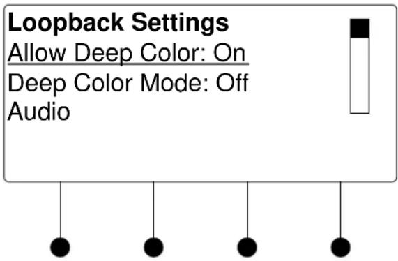
- Turn the selection knob to view audio details or view EDID information.
a. To view audio details:
i. Turn the selection knob to highlight Audio and press the ENTER button.
Audio Details

ii. Press the MENU button to return to the Loopback Settings.
b. To view EDID information about the display device connected to the HDMI OUT port:
i. Turn the selection knob to highlight EDID Information and press the ENTER button.
EDID Information
EDID Information
Manufacturer: SHP
Name: SHARP HDMI
Timing: 1920x1080 @ 60Hz
natural_image
Simple diagram of four black dots suspended by strings (no text or symbols)ii. Press the MENU button to return to the Loopback Settings.
- Press the MENU button to return to the list of options for the input card.
Audio Output Level
The output level of the audio output can be adjusted. To adjust the audio output level:
- Turn the selection knob to highlight Audio Output Level and press the ENTER button
Audio Output Level

bar
Audio Output Level | Audio Level | Value | | :--- | :--- | | -52 dB | -52 dB |- Turn the selection knob to adjust the audio output level.
- Press the MENU button to return to the list of options for the input card.
Use the Restore Defaults function to reset the card to its factory settings. The card's factory settings are:
• Color Space Mode: Force RGB
- Enable/Disable input: Input enabled
To restore the card's default settings:
- Turn the selection knob to highlight Restore Defaults and press the ENTER button.
- Press the soft button labeled Yes to restore the default setting or press the soft button labeled No to cancel and return to the list of options for the input card.
Restore Defaults
DMC-VID4
The front panel controls for the DMC-VID4 allow the user to rename the input and configure each of the inputs.
DMC-VID4 Controls

Using the DMC-VID4 controls, the user can:
- Change the input name.
- Select the input to be viewed.
- Select the input rotate rate.
- Adjust the input signals.
• View details on the signal delivered to the HDMI OUT (loopback) port. - View details about the device connected to the HDMI OUT (loopback) port.
- Restore the default settings.
Name/Rename the Input
To name and/or rename the input:
- Turn the selection knob to highlight Name and press the ENTER button. A cursor will appear next to the current name and controls for changing the name will also be displayed. To cancel and return to the list of options for the input card, press the MENU button.
Edit Input Name
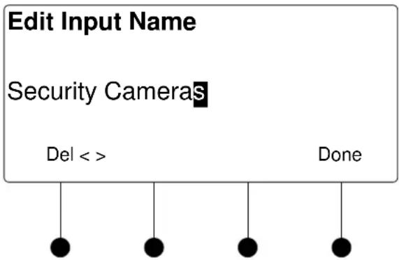
flowchart
graph TD
    A["Edit Input Name"] --> B["Security Cameras"]
    B --> C["Del <>"]
    B --> D["Done"]
- Select letters (upper and lower-case), numbers, or other characters by turning the selection knob until the desired letter, number, or other character is displayed on the LCD. Move the cursor to another position by pressing the soft buttons labeled ◀ and ▶. To delete a character, press the soft button marked Del.
NOTE: The maximum length for any input name is 32 characters.
- After the new name has been entered, press Done to save the name and return to the list of options for the input card.
Select Input
The DMC-VID4 can select video from any of the four inputs for viewing. The DMC-VID4 can also be set to show feeds from all four inputs simultaneously or switch between inputs at a specified rotate rate. To select an input to view:
- Turn the selection knob to highlight Input Select and press the ENTER button.
Select Input to View

- Turn the selection knob to highlight an input and press the ENTER button. The current selection is indicated with an asterisk (*).
In addition to choosing an individual input, the user can select to view all of the inputs simultaneously (All Inputs) or have the display rotate between the inputs (Rotate Inputs). If Rotate Inputs is selected, the rotate rate must be selected as described in “Input Rotate Rate” below.
- Press the MENU button to return to the list of options for the DMC-VID4.
Input Rotate Rate
If the DMC-VID4 is set to rotate the inputs that are displayed, the rotate rate between inputs must be set. To select a rotate rate:
- Turn the selection knob to highlight Input Rotate Rate and press the ENTER button.
Input Rotate Rate
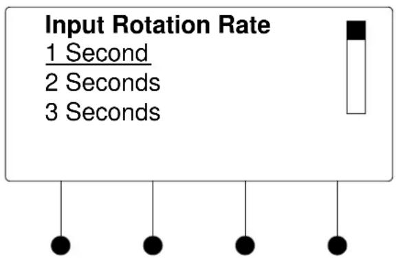
bar
Input Rotation Rate | Time | Input Rotation Rate | |---|---| | 1 Second | Black square | | 2 Seconds | White vertical bar | | 3 Seconds | White vertical bar |- Turn the selection knob to highlight a rotate rate and press the ENTER button. Rotate rates from one to 60 seconds can be selected. The current selection is indicated with an asterisk (*).
- Press the MENU button to return to the list of options for the DMC-VID4.
Video Input Settings
Each of the inputs on the DMC-VID4 can be configured and monitored. To configure or monitor a video input:
- Turn the selection knob to highlight the video input to be configured or monitored (Video Input 1 Settings through Video Input 4 Settings) and press the ENTER button.
Video Settings
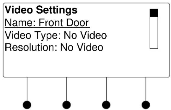
- Turn the selection knob to view information on video type, resolution, frame rate and aspect ratio. The name of the selected video input and the picture controls for the selected video input can also be adjusted.
a. The name of the video input can be set to provide a label for the image when it is displayed. To change the name assigned to the video input:
i. Turn the selection knob to highlight Name and press the ENTER button.
ii. A cursor will appear next to the current name and controls for changing the name will also be displayed. To cancel and return to the list of options for the input card, press the MENU button.
Edit Input Name
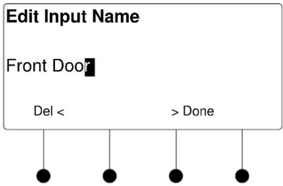
flowchart
graph TD
    A["Edit Input Name"] --> B["Front Door"]
    B --> C["Del <"]
    B --> D["> Done"]
iii. Select letters (upper and lower-case), numbers, or other characters by turning the selection knob until the desired letter, number, or other character is displayed on the LCD. Move the cursor to another position by pressing the soft buttons labeled ◀ and ▶. To delete a character, press the soft button marked Del.
NOTE: The maximum length for any input name is 32 characters.
iv. After the new name has been entered, press Done to save the name and return to the list of selections for the video input.
b. Picture controls can be used to adjust the picture's brightness, contrast, saturation, and hue levels. To adjust the picture:
i. Turn the selection knob to highlight Picture Controls and press the ENTER button.
ii. Turn the selection knob to highlight the picture control to be adjusted and press the ENTER button. Controls are available for brightness, contrast, saturation, and hue.
Brightness Control

Contrast Control
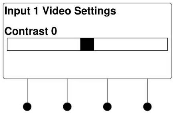
Saturation Control

Hue Control
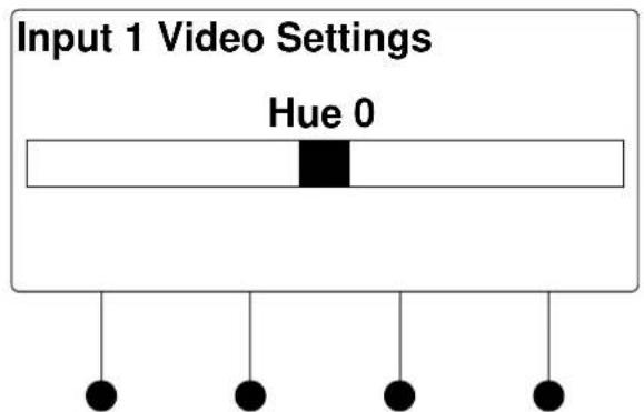
iii. Turn the selection knob to display the desired level and press the ENTER button to save the setting and return to the list of picture controls.
iv. Press the MENU button to return to the list of options for the video input.
- Press the MENU button to return to the list of options for the input card.
Loopback Settings
The DMC-VID4 can display information about the device connected to the HDMI OUT port as well as information on the deep color setting of the signal passed to the HDMI OUT port on the DMC-VID4. To view the loopback settings:
- Turn the selection knob to highlight Loopback Settings and press the ENTER button.
Loopback Settings
Loopback Settings Allow Deep Color: On Deep Color Mode: Off EDID Information

natural_image
Simple diagram of four black dots suspended by strings (no text or symbols)- Turn the selection knob to view available information, enable/disable deep color, or view EDID information.
a. The loopback output can be set to enable or disable the deep color feature of the carried video signal. To enable or disable deep color:
i. Turn the selection knob to highlight Allow Deep Color and press the ENTER button.
Allow Deep Color Mode
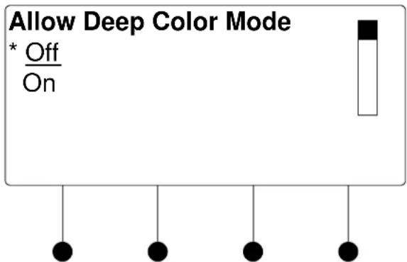
ii. The current selection is indicated with an asterisk (*). Turn the selection knob to highlight Off or On and press the ENTER button.
b. To view EDID information about the display device connected to the HDMI OUT port:
i. Turn the selection knob to highlight EDID Information and press the ENTER button.
EDID Information
EDID Information
Manufacturer: SHP
Name: SHARP HDMI
Timing: 1920x1080 @ 60Hz

natural_image
Simple diagram of four black dots suspended by vertical lines (no text or symbols)ii. Press the MENU button to return to the Loopback Settings.
- Press the MENU button to return to the list of options for the input card.
Restore Defaults
Use the Restore Defaults function to reset the card to its factory settings. The card's factory settings are:
- Input Select: Input 1
- Rotate Rate: 3 seconds
• Image Display (Full or Quad): Full
• Image Format: NTSC
• Image Cycle (Enable/Disable): Disabled
• Text Overscan: 5 - Loopback Allow Deep Color: On
• Color Space Mode: Force RGB - Enable/Disable for inputs 1-4: All inputs enabled
• Text Color for inputs 1-4: White
• Text Box Color for inputs 1-4: Black
• Text Position for inputs 1-4: Top Left
• Brightness level for inputs 1-4: 0
• Contrast level for inputs 1-4: 0
• Saturation level for inputs 1-4: 0
• Hue level for inputs 1-4: 0
• Input Names for inputs 1-4: Camera 1- Camera 4
To restore the card's default settings:
- Turn the selection knob to highlight Restore Defaults and press the ENTER button.
- Press the soft button labeled Yes to restore the default setting or press the soft button labeled No to cancel and return to the list of options for the input card.
DMC-VID-BNC
The front panel controls for the DMC-VID-BNC allow the user to rename the input, adjust the picture, and view information on the incoming video source and the outgoing HDMI signal.
DMC-VID-BNC Controls
5. DMC-VID-BNC Comm
Name:
Video Settings
Audio Settings
Using the DMC-VID-BNC controls, the user can:
- Change the input name.
• View details on the video portion of the incoming signal
• View details on the audio portion of the incoming signal.
• View details on the signal delivered to the HDMI OUT (loopback) port. - View details about the device connected to the HDMI OUT (loopback) port.
- Restore the default settings.
Name/Rename the Input
To name and/or rename the input:
- Turn the selection knob to highlight Name and press the ENTER button. A cursor will appear next to the current name and controls for changing the name will also be displayed. To cancel and return to the list of options for the input card, press the MENU button.
Edit Input Name

flowchart
graph TD
    A["Edit Input Name"] --> B["Video"]
    B --> C["Del"]
    B --> D["<"]
    B --> E[">"]
    B --> F["Done"]
- Select letters (upper and lower-case), numbers, or other characters by turning the selection knob until the desired letter, number, or other character is displayed on the LCD. Move the cursor to another position by pressing the soft buttons labeled ◀ and ▶. To delete a character, press the soft button marked Del.
NOTE: The maximum length for any input name is 32 characters.
- After the new name has been entered, press Done to save the name and return to the list of options for the input card.
Video Settings
The DMC-VID-BNC can display information about the video portion of the incoming signal and adjust the picture. To view and/or adjust the video settings:
- Turn the selection knob to highlight Video Settings and press the ENTER button.
Video Settings
Video Settings Input Type: Component Video Type: Interlaced Resolution: 1920x1080
Turn the selection knob to view information on input type, video type, resolution, frame rate, and aspect ratio.
- The picture settings can also be adjusted.
Picture controls can be used to adjust the picture's brightness, contrast, saturation, and hue levels. To adjust the picture:
a. Turn the selection knob to highlight Picture Controls and press the ENTER button.
b. Turn the selection knob to highlight the picture control to be adjusted and press the ENTER button. Controls are available for brightness, contrast, saturation, and hue.
Brightness Control

Contrast Control

Saturation Control

Hue Control

c. Turn the selection knob to display the desired level and press the ENTER button to save the setting and return to the list of picture controls.
d. Press the MENU button to return to the list of options for video settings.
- Press the MENU button to return to the list of options for the input card.
Audio Settings
The DMC-VID-BNC can display information about the audio portion of the incoming signal. Available information includes format, frequency, and channels. To view audio settings:
- Turn the selection knob to highlight Audio Settings and press the ENTER button.
Audio Settings

- Press the MENU button to return to the list of options for the input card.
Loopback Settings
The DMC-VID-BNC can display information about the device connected to the HDMI OUT port as well as information about the signal passed to the HDMI OUT port on the DMC-VID-BNC. Available information includes deep color setting, audio details and EDID information. To view the loopback settings:
- Turn the selection knob to highlight Loopback Settings and press the ENTER button.
Loopback Settings

- Turn the selection knob to view available information, enable/disable deep color, view audio details, or view EDID information.
a. The loopback output can be set to enable or disable the deep color feature of the carried video signal. To enable or disable deep color:
i. Turn the selection knob to highlight Allow Deep Color and press the ENTER button.
Allow Deep Color Mode

ii. The current selection is indicated with an asterisk (*). Turn the selection knob to highlight Off or On and press the ENTER button.
b. To view audio details:
i. Turn the selection knob to highlight Audio and press the ENTER button.
Audio Details
Audio
Format: PCM
Frequency: 48.0kHz
Channels: 2
ii. Press the MENU button to return to the Loopback Settings.
c. To view EDID information about the display device connected to the HDMI OUT port:
i. Turn the selection knob to highlight EDID Information and press the ENTER button.
EDID Information
EDID Information
Manufacturer: SHP
Name: SHARP HDMI
Timing: 1920x1080 @ 60Hz
ii. Press the MENU button to return to the Loopback Settings.
- Press the MENU button to return to the list of options for the input card.
Restore Defaults
Use the Restore Defaults function to reset the card to its factory settings. The card's factory settings are:
- Loopback Allow Deep Color: On
• Color Space Mode: Force RGB - Enable/Disable input: Input enabled
- Brightness level: 0
- Contrast level: 0
- Saturation level: 0
- Hue level: 0
To restore the card's default settings:
- Turn the selection knob to highlight Restore Defaults and press the ENTER button.
- Press the soft button labeled Yes to restore the default setting or press the soft button labeled No to cancel and return to the list of options for the input card.
DMC-VID-RCA-A
The front panel controls for the DMC-RCA-A allow the user to rename the input, adjust the picture, and view information on the incoming component video source and the outgoing HDMI signal.
DMC- VID-RCA-A Controls
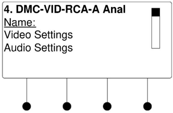
Using the DMC-VID-RCA-A controls, the user can:
- Change the input name.
• View details on the video portion of the incoming signal
• View details on the audio portion of the incoming signal.
• View details on the signal delivered to the HDMI OUT (loopback) port. - View details about the device connected to the HDMI OUT (loopback) port.
- Restore the default settings.
Name/Rename the Input
To name and/or rename the input:
- Turn the selection knob to highlight Name and press the ENTER button. A cursor will appear next to the current name and controls for changing the name will also be displayed. To cancel and return to the list of options for the input card, press the MENU button.
Edit Input Name
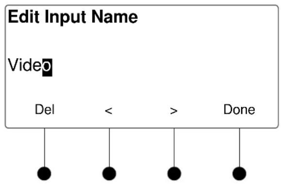
flowchart
graph TD
    A["Edit Input Name"] --> B["Video"]
    B --> C["Del"]
    B --> D["<"]
    B --> E[">"]
    B --> F["Done"]
- Select letters (upper and lower-case), numbers, or other characters by turning the selection knob until the desired letter, number, or other character is displayed on the LCD. Move the cursor to another position by pressing the soft buttons labeled ◀ and ▶. To delete a character, press the soft button marked Del.
NOTE: The maximum length for any input name is 32 characters.
- After the new name has been entered, press Done to save the name and return to the list of options for the input card.
Video Settings
The DMC-VID-RCA-A can display information about the video portion of the incoming signal and adjust the picture. To view and/or adjust the video settings:
- Turn the selection knob to highlight Video Settings and press the ENTER button.
Video Settings
Video Settings Input Type: Component Video Type: Interlaced Resolution: 1920x1080
Turn the selection knob to view information on input type, video type, resolution, frame rate, and aspect ratio.
- The picture settings can also be adjusted.
Picture controls can be used to adjust the picture's brightness, contrast, saturation, and hue levels. To adjust the picture:
a. Turn the selection knob to highlight Picture Controls and press the ENTER button.
b. Turn the selection knob to highlight the picture control to be adjusted and press the ENTER button. Controls are available for brightness, contrast, saturation, and hue.
Brightness Control

Contrast Control
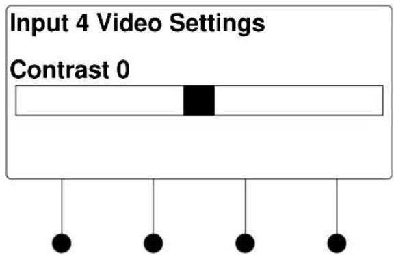
Saturation Control

Hue Control

c. Turn the selection knob to display the desired level and press the ENTER button to save the setting and return to the list of picture controls.
d. Press the MENU button to return to the list of options for video settings.
- Press the MENU button to return to the list of options for the input card.
Audio Settings
The DMC-VID-RCA-A can display information about the audio portion of the incoming signal. Available information includes format, frequency, and channels. To view audio settings:
- Turn the selection knob to highlight Audio Settings and press the ENTER button.
Audio Settings

- Press the MENU button to return to the list of options for the input card.
Loopback Settings
The DMC-VID-RCA-A can display information about the device connected to the HDMI OUT port as well as information about the signal passed to the HDMI OUT port on the DMC-VID-RCA-A. Available information includes deep color setting, audio details and EDID information. To view the loopback settings:
- Turn the selection knob to highlight Loopback Settings and press the ENTER button.
Loopback Settings
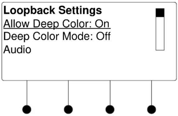
- Turn the selection knob to view available information, enable/disable deep color, view audio details, or view EDID information.
a. The loopback output can be set to enable or disable the deep color feature of the carried video signal. To enable or disable deep color:
i. Turn the selection knob to highlight Allow Deep Color and press the ENTER button.
Allow Deep Color Mode

ii. The current selection is indicated with an asterisk (*). Turn the selection knob to highlight Off or On and press the ENTER button.
b. To view audio details:
i. Turn the selection knob to highlight Audio and press the ENTER button.
Audio Details

ii. Press the MENU button to return to the Loopback Settings.
c. To view EDID information about the display device connected to the HDMI OUT port:
i. Turn the selection knob to highlight EDID Information and press the ENTER button.
EDID Information

ii. Press the MENU button to return to the Loopback Settings.
- Press the MENU button to return to the list of options for the input card.
Restore Defaults
Use the Restore Defaults function to reset the card to its factory settings. The card's factory settings are:
- Loopback Allow Deep Color: On
• Color Space Mode: Force RGB - Enable/Disable input: Input enabled
- Brightness level: 0
- Contrast level: 0
- Saturation level: 0
- Hue level: 0
To restore the card's default settings:
- Turn the selection knob to highlight Restore Defaults and press the ENTER button.
- Press the soft button labeled Yes to restore the default setting or press the soft button labeled No to cancel and return to the list of options for the input card.
DMC-VID-RCA-D
The front panel controls for the DMC-RCA-D allow the user to rename the input, adjust the picture, and view information on the incoming component video source and the outgoing HDMI signal.
DMC- VID-RCA-D Controls

Using the DMC-VID-RCA-D controls, the user can:
- Change the input name.
• View details on the video portion of the incoming signal
• View details on the audio portion of the incoming signal.
• View details on the signal delivered to the HDMI OUT (loopback) port. - View details about the device connected to the HDMI OUT (loopback) port.
- Restore the default settings.
Name/Rename the Input
To name and/or rename the input:
- Turn the selection knob to highlight Name and press the ENTER button. A cursor will appear next to the current name and controls for changing the name will also be displayed. To cancel and return to the list of options for the input card, press the MENU button.
Edit Input Name

flowchart
graph TD
    A["Edit Input Name"] --> B["DVD"]
    B --> C["Del <>"]
    B --> D["Done"]
- Select letters (upper and lower-case), numbers, or other characters by turning the selection knob until the desired letter, number, or other character is displayed on the LCD. Move the cursor to another position by pressing the soft buttons labeled ◀ and ▶. To delete a character, press the soft button marked Del.
NOTE: The maximum length for any input name is 32 characters.
- After the new name has been entered, press Done to save the name and return to the list of options for the input card.
Video Settings
The DMC-VID-RCA-D can display information about the video portion of the incoming signal and adjust the picture. To view and/or adjust the video settings:
- Turn the selection knob to highlight Video Settings and press the ENTER button.
Video Settings
Video Settings Input Type: Component Video Type: Interlaced Resolution: 1920x1080
Turn the selection knob to view information on input type, video type, resolution, frame rate, and aspect ratio.
- The picture settings can also be adjusted.
Picture controls can be used to adjust the picture's brightness, contrast, saturation, and hue levels. To adjust the picture:
a. Turn the selection knob to highlight Picture Controls and press the ENTER button.
b. Turn the selection knob to highlight the picture control to be adjusted and press the ENTER button. Controls are available for brightness, contrast, saturation, and hue.
Brightness Control
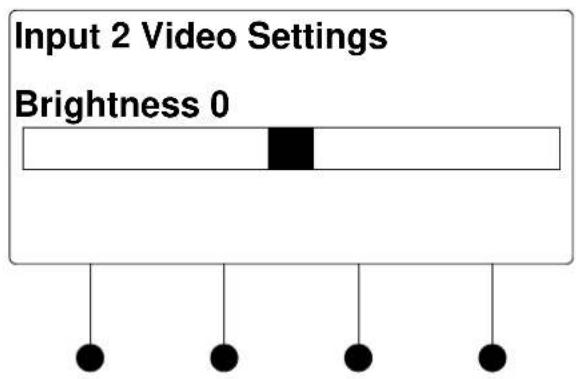
Contrast Control

Saturation Control
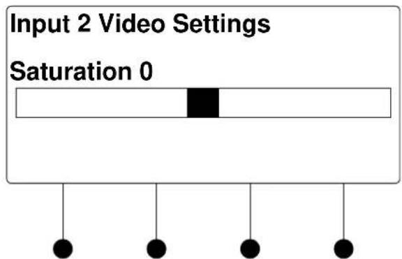
Hue Control

c. Turn the selection knob to display the desired level and press the ENTER button to save the setting and return to the list of picture controls.
d. Press the MENU button to return to the list of options for video settings.
- Press the MENU button to return to the list of options for the input card.
Audio Settings
The DMC-VID-RCA-D can display information about the audio portion of the incoming signal. Available information includes format, frequency, and channels. To view audio settings:
- Turn the selection knob to highlight Audio Settings and press the ENTER button.
Audio Settings

- Press the MENU button to return to the list of options for the input card.
Loopback Settings
The DMC-VID-RCA-D can display information about the device connected to the HDMI OUT port as well as information about the signal passed to the HDMI OUT port on the DMC-RCA-D. Available information includes deep color setting, audio details and EDID information. To view the loopback settings:
- Turn the selection knob to highlight Loopback Settings and press the ENTER button.
Loopback Settings

- Turn the selection knob to view available information, enable/disable deep color, view audio details, or view EDID information.
a. The loopback output can be set to enable or disable the deep color feature of the carried video signal. To enable or disable deep color:
i. Turn the selection knob to highlight Allow Deep Color and press the ENTER button.
Allow Deep Color Mode

ii. The current selection is indicated with an asterisk (*). Turn the selection knob to highlight Off or On and press the ENTER button.
b. To view audio details:
i. Turn the selection knob to highlight Audio and press the ENTER button.
Audio Details
Audio
Format: PCM
Frequency: 48.0kHz
Channels: 2
ii. Press the MENU button to return to the Loopback Settings.
c. To view EDID information about the display device connected to the HDMI OUT port:
i. Turn the selection knob to highlight EDID Information and press the ENTER button.
EDID Information
EDID Information
Manufacturer: SHP
Name: SHARP HDMI
Timing: 1920x1080 @ 60Hz
ii. Press the MENU button to return to the Loopback Settings.
- Press the MENU button to return to the list of options for the input card.
Restore Defaults
Use the Restore Defaults function to reset the card to its factory settings. The card's factory settings are:
- Loopback Allow Deep Color: On
• Color Space Mode: Force RGB - Enable/Disable input: Input enabled
- Brightness level: 0
- Contrast level: 0
- Saturation level: 0
- Hue level: 0
To restore the card's default settings:
- Turn the selection knob to highlight Restore Defaults and press the ENTER button.
- Press the soft button labeled Yes to restore the default setting or press the soft button labeled No to cancel and return to the list of options for the input card.
Appendix C: Output Configuration
This appendix contains detailed instructions for using the DM switcher's front panel controls to configure the outputs on a DM switcher.
Select An Output
To view/change the configuration settings for an output:
- Open the Outputs section of Installer Tools as described on page 43.
- Turn the selection knob to highlight the output to be configured and press the ENTER button.
- To edit or view the details of an output, turn the selection knob to highlight an output and press the ENTER button. A list of options is displayed. Turn the selection knob to highlight an option and press the ENTER button.
Output Settings for Output 1

- To return to the list of outputs, press the MENU button.
Name/Rename an Output
To name and/or rename an output:
- Open the Outputs section and select an output as described above.
- Turn the selection knob to highlight the name of the output to be named/renamed and press the ENTER button. A cursor will appear next to the current name and controls for changing the name will also be displayed. To cancel, press the MENU button.
Edit Output Name
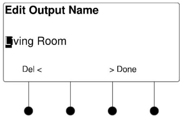
flowchart
graph TD
    A["Edit Output Name"] --> B["Living Room"]
    B --> C["Del <"]
    B --> D["> Done"]
- Select letters (upper and lower-case), numbers, or other characters by turning the selection knob until the desired letter, number, or other character is displayed on the LCD. Move the cursor to another position by pressing the soft buttons labeled ◀ and ▶. To delete a character, press the soft button marked Del.
NOTE: The maximum length for any output name is 32 characters.
- After the new name has been entered, press Done to save the name and return to the list of options for the output.
DM CAT Output Information (DM CAT-Equipped Outputs)
The DM output can provide information on the HDCP state, the deep color setting, the audio signal that is being passed through, EDID information, the selected DM cable type, and DM device depth. To view information on the DM CAT output:
- Open the Outputs section and select an output as described on page 170.
Turn the selection knob to highlight DM Output Settings and press the ENTER button. A list of available data will be displayed. Some categories such as Audio, EDID Device Information, Allow Deep Color, DM Cable Type and DM Device Depth, will display detailed information when highlighted with the selection knob and selected by pressing the ENTER button.
a. The output can be set to enable or disable the deep color feature of the carried video signal. To enable or disable deep color:
i. Turn the selection knob to highlight Allow Deep Color and press the ENTER button.
Allow Deep Color Mode

ii. The current selection is indicated with an asterisk (*). Turn the selection knob to highlight Off or On and press the ENTER button.
b. When DM Cable Type is selected, the type of DM cable used to connect the output can be displayed or changed.
DM Cable Type
DM Cable Type
* Digital Media Category 6 Category 5e
The selected cable type is displayed with an asterisk (*). To select a different cable type:
i. Turn the selection knob to highlight the cable type to be used and press the ENTER button. An asterisk will appear next to the selected cable type.
ii. Press the MENU button to return to the list of available information.
- To exit and return to the list of available functions, press the MENU button.
HDMI Output Information (HDMI-Equipped Outputs)
Cards equipped with HDMI outputs can provide information on the HDCP state, the deep color setting, and the audio signal that is being passed through. To view information on the HDMI output:
- Open the Outputs section and select an output as described on page 170.
- Turn the selection knob to highlight HDMI Output Settings and press the ENTER button. A list of available data will be displayed. Some categories such as Audio and EDID Device Information will display detailed information when highlighted with the selection knob and selected by pressing the ENTER button. Allow Deep Color can be used to determine whether deep color can be sent over the output while Audio Output Level sets the level of the analog audio output.
- Allow Deep Color:
a. Turn the selection knob to highlight Allow Deep Color and press the ENTER button.
Allow Deep Color Mode

b. The current selection is indicated with an asterisk (*). Turn the selection knob to highlight Off or On and press the ENTER button.
• Audio Output Level:
a. Turn the selection knob to highlight Audio Output Level and press the ENTER button.
Audio Output Level
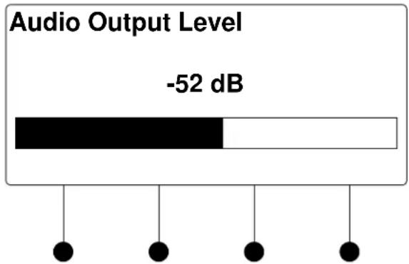
b. Turn the selection knob to adjust the audio output level.
c. Press the MENU button to return to the list of options for the output card.
- To exit and return to the list of available functions, press the MENU button.
Fiber Output Information (DM Fiber-Equipped Outputs)
Cards equipped with DM fiber outputs can provide information on the HDCP state, the deep color setting, the audio signal that is being passed through, and EDID. To view information on the fiber output:
- Open the Outputs section and select an output as described on page 170.
- Turn the selection knob to highlight Fiber Output Settings and press the ENTER button. A list of available data will be displayed. Some categories such as Audio and EDID Device Information will display detailed information when highlighted with the selection knob and selected by pressing the ENTER button. Allow Deep Color can be used to determine whether deep color can be sent over the output. To enable or disable deep color:
a. Turn the selection knob to highlight Allow Deep Color and press the ENTER button.
Allow Deep Color Mode
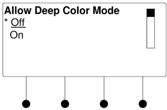
b. The current selection is indicated with an asterisk (*). Turn the selection knob to highlight Off or On and press the ENTER button.
- To exit and return to the list of available functions, press the MENU button.
Restore Defaults
To restore the default settings of the output:
- Turn the selection knob to highlight Restore Defaults and press the ENTER button.
- Press the soft button labeled Yes to restore the default settings or press the soft button labeled No to cancel and return to the list of available functions.
If Yes is chosen, the settings will be restored as follows:
• Output 1 Deep Color Setting: 8 bit
- Output 2 Deep Color Setting (HDMI outputs on HDMI-equipped cards): 12 bit
• DM Cable Type (DM-equipped cards): DM Cable
• Maximum Pixel Rate on Output 1: 165
• Maximum Pixel Rate on Output 2 (HDMI output on outputs 1, 3, 5 and 7): 225
- Stream Name: Reverts to number of output. (i.e. The name assigned to Stream 1 will be renamed "1".)
Glossary
| 1080i | An HDTV standard that specifies an interlaced resolution of 1920 x 1080. |
| 1080p | An HDTV standard that specifies a non-interlaced resolution of 1920 x 1080. |
| 16:9 | Sometimes expressed as 16 x 9 or 16 by 9 (known as 1.78:1 in the film world); the standard DTV wide-screen television screen size, or aspect ratio--16 arbitrary units wide by 9 arbitrary units high, as compared to a standard TV aspect ratio of 4:3. The phrase describes the shape of a TV set or program, not an actual inch measurement. |
| 4:3 | Standard "square" NTSC TV screen-size aspect ratio of 4 arbitrary units wide by 3 arbitrary units high; often expressed as 4x3 or 4 by 3. It was originally known as the Academy Ratio (as in Academy of Motion Picture Arts and Sciences, the film industry organization that awards the Oscars) prior to 1954 and the introduction of wide-screen aspect-ratio film formats; also known in the film world as 1.33:1. |
| 480i | 480 interlaced; a form of standard-definition digital television (SDTV) that approximates the quality of analog television but not considered high-definition television (HDTV). Even though the native resolution of DVDs is 480p, they are viewed at 480i on an NTSC analog television. |
| 480p | 480 progressive; form of standard-definition digital television (SDTV) comparable to VGA computer displays but not considered high-definition television (HDTV), though 480p is discernibly cleaner and slightly sharper than analog television. The native resolution of DVD is 480p, but that resolution can be seen only if a DVD player outputs a progressive-scan signal and the DTV has progressive-scan or component-video inputs; it is also known as EDTV. |
| 720p | 720 progressive; one of two currently used formats designated as high-definition television in the ATSC DTV standard, this technology comprises 720 vertical pixels and 1,280 horizontal pixels. The p stands for progressive, as opposed to interlaced, scanning, which is used in the other accepted HDTV standard, known as 1080i. Contrary to myth, 720p is not inferior to 1080i; 720p has fewer lines but also has the advantages of progressive scanning and a constant vertical resolution of 720 lines, making it better able to handle motion. |
| Anamorphic | Adopted from the film technique of shooting a wide-screen image on a square 35mm frame, it is the process of compressing wide-screen images to fit into the squarer standard 4:3 television signal. The images are then expanded for viewing in their original format on a wide-screen display device. Wide-screen or letterboxed DVDs that are not anamorphic have less detail when projected on a wide-screen monitor. In other words, a non-anamorphic wide-screen DVD is designed to be shown letterboxed on a standard "square" TV but appears with a black box all around the image |
when shown on a larger 16:9 widescreen TV. To fill a 16:9 screen, a non-anamorphic DVD has to be blown up, resulting in loss of resolution and detail. Conversely, a DVD that is anamorphic, enhanced for 16:9, or enhanced for wide-screen delivers 33 percent more resolution than regular letterboxed transfers, is designed to be shown on a 16:9 TV, and does not need to be blown up. When one of these DVDs is shown on a "square" TV, it is often subject to anamorphic down-conversion artifacts unless the TV has a vertical compression feature.
Anamorphic down-conversion
Processing present in all DVD players that converts the image from an anamorphic DVD for display on a regular 4:3 TV. In the initial setup of a DVD player is a choice between a 16:9 or a 4:3 TV; the 4:3 options engage this processing, which often introduces artifacts such as jaggies and undulations during pans.
Aspect ratio
The ratio of width to height in a video picture or other graphic image. Standard U.S. TV broadcasts and computer monitors feature a 4:3 aspect ratio; HDTV has a much wider 16:9 ratio.
Authentication
Authentication ensures that digital data transmissions are delivered to the intended receiver. Authentication also assures the receiver of the integrity of the message and its source (where or whom it came from). The simplest form of authentication requires a username and a password to gain access to a particular account. But authentication protocols can also be based on secret-key encryption, such as DES, or on public-key systems using digital signatures.
Component video
The elements that make up a video signal, consisting of luminance and two separate chrominance signals, expressed either as Y R-Y B-Y or Y P b P r .
Deep Color
A color depth standard associated with high-definition TVs and video gear that include HDMI connections. The deep color standard supports 10-bit, 12-bit and 16-bit color bit depths, up from 8-bit, which is the current standard for consumer video. DigitalMedia supports all but the 16-bit color depth. All earlier versions of HDMI supported just 8-bit color. (Because video is based on three primary colors, you'll sometimes see deep color described as 30-bit, 36-bit and 48-bit.) A higher color bit depth enables finer gradations between different shades of the same color for smoother gradients and reduced color banding. Deep color gives TVs the potential to display billions rather than millions of colors, but in order to see that improvement, the entire video production chain has to use it (camera, editing, format, player, display).
DisplayPort
A digital display interface standard put forth by the Video Electronics Standards Association (VESA) that defines a new license-free, royalty-free, digital audio/video interconnect, intended to be used primarily between a computer and its display monitor, or a computer and a home-theater system.
Down-convert
In DTV, the conversion from a higher-resolution input signal number to a lower one. For example, some DTV receivers can be set to down-convert an HDTV 1080i signal to a standard 480i signal that any TV can display.
DRM
Digital Rights Management; a secure technology that enables the copyright owner of a piece of intellectual property (such as a music, video, or text file) to specify what a user can do with it. Typically, this is used to offer downloads that can't be played or burned to CD without paying for a license.
DTV/Digital television
Generic term that refers to all digital television formats, including high-definition television (HDTV) and standard-definition television (SDTV).
DVI (Digital Visual Interface)
A digital interface specification created by an industry consortium, the Digital Display Working Group. This universal standard for connecting flat-panel monitors is also used for data projectors, plasma displays, and digital TVs. Using a DVI connector and port, a digital signal sent to an analog device is converted into an analog signal (if the device is digital, such as a flat-panel monitor, no conversion is necessary). There are three different DVI configurations: DVI-A for analog signals, DVI-D for digital signals, and DVI-I (integrated) for both analog and digital signals.
EDID (Extended Display Identification Data).
The information transmitted from a display to a source announcing its resolution capabilities.
HDMI (High-Definition Multimedia Interface)
USB-like digital video connectivity standard designed as a successor to DVI; can transmit both digital audio and video signals; incorporates HDCP digital copy protection.
Interlaced scanning
Scan method used by the majority of televisions and the 1080i HDTV format. As opposed to progressive scanning in which the CRT's electron beam scans or "paints" all lines at once, interlaced scanning TVs paint odd-numbered lines in succession, then go back and fill in the remaining even-numbered lines. This method is more prone to artifacts and less stable than progressive.
KSV (Key Selection Vector)
A set of numbers transmitted between HDCP-protected sources and sinks (displays/receivers) during the authentication “handshake” to validate that the devices are authorized to receive the content. Some HDMI sources have limited buffer space to hold KSVs and as such, can only be routed to a few HDMI devices before their buffer overflows and content playback stops.
Progressive scan
A method of displaying images on a CRT monitor or a high-definition TV in which all the lines of a picture are drawn in one quick burst, from left to right and from top to bottom. Compare this to interlacing, in which every other line is displayed in two successive swoops to form a complete picture.
SDTV
Standard-definition television. Digital television format that includes 480-line resolution in both interlaced (480i) and progressively scanned (480p) formats; offers discernible improvement over conventional analog NTSC picture resolution, with less noise; similar to DVD or satellite TV quality but not considered high-definition television (HDTV).
Wide-screen
Image with an aspect ratio greater than 1.33:1 or a picture wider and narrower than a standard television image. Typically refers to TVs in the 16:9 aspect ratio.
YP_bP_r
Luminance, two chrominance channels of blue minus luminance, red minus luminance. This technical shorthand for component video is also written as Y C b C r or Y R-Y B-Y.
Return and Warranty Policies
Merchandise Returns / Repair Service
-
No merchandise may be returned for credit, exchange or service without prior authorization from Crestron. To obtain warranty service for Crestron products, contact an authorized Crestron dealer. Only authorized Crestron dealers may contact the factory and request an RMA (Return Merchandise Authorization) number. Enclose a note specifying the nature of the problem, name and phone number of contact person. RMA number and return address.
-
Products may be returned for credit, exchange or service with a Crestron Return Merchandise Authorization (RMA) number. Authorized returns must be shipped freight prepaid to Crestron, 6 Volvo Drive, Rockleigh, N.J. or its authorized subsidiaries, with RMA number clearly marked on the outside of all cartons. Shipments arriving freight collect or without an RMA number shall be subject to refusal. Crestron reserves the right in its sole and absolute discretion to charge a 15% restocking fee plus shipping costs on any products returned with an RMA.
-
Return freight charges following repair of items under warranty shall be paid by Crestron, shipping by standard ground carrier. In the event repairs are found to be non-warranty, return freight costs shall be paid by the purchaser.
Crestron Limited Warranty
Crestron Electronics, Inc. warrants its products to be free from manufacturing defects in materials and workmanship under normal use for a period of three (3) years from the date of purchase from Crestron, with the following exceptions: disk drives and any other moving or rotating mechanical parts, pan/tilt heads and power supplies are covered for a period of one (1) year; touch screen display and overlay components are covered for 90 days; batteries and incandescent lamps are not covered.
This warranty extends to products purchased directly from Crestron or an authorized Crestron dealer. Purchasers should inquire of the dealer regarding the nature and extent of the dealer's warranty, if any.
Crestron shall not be liable to honor the terms of this warranty if the product has been used in any application other than that for which it was intended or if it has been subjected to misuse, accidental damage, modification or improper installation procedures. Furthermore, this warranty does not cover any product that has had the serial number altered, defaced or removed.
This warranty shall be the sole and exclusive remedy to the original purchaser. In no event shall Crestron be liable for incidental or consequential damages of any kind (property or economic damages inclusive) arising from the sale or use of this equipment. Crestron is not liable for any claim made by a third party or made by the purchaser for a third party.
Crestron shall, at its option, repair or replace any product found defective, without charge for parts or labor. Repaired or replaced equipment and parts supplied under this warranty shall be covered only by the unexpired portion of the warranty.
Except as expressly set forth in this warranty, Crestron makes no other warranties, expressed or implied, nor authorizes any other party to offer any warranty, including any implied warranties of merchantability or fitness for a particular purpose. Any implied warranties that may be imposed by law are limited to the terms of this limited warranty. This warranty statement supersedes all previous warranties.
GNU General Public License
Version 2, June 1991
Copyright (C) 1989, 1991 Free Software Foundation, Inc., 51 Franklin Street, Fifth Floor, Boston, MA 02110-1301 USA Everyone is permitted to copy and distribute verbatim copies of this license document but changing it is not allowed.
PREAMBLE
The licenses for most software are designed to take away your freedom to share and change it. By contrast, the GNU General Public License is intended to guarantee your freedom to share and change free software--to make sure the software is free for all its users. This General Public License applies to most of the Free Software Foundation's software and to any other program whose authors commit to using it. (Some other Free Software Foundation software is covered by the GNU Lesser General Public License instead.) You can apply it to your programs too.
When we speak of free software, we are referring to freedom, not price. Our General Public Licenses are designed to make sure that you have the freedom to distribute copies of free software (and charge for this service if you wish), that you receive source code or can get it if you want it, that you can change the software or use pieces of it in new free programs and that you know you can do these things.
To protect your rights, we need to make restrictions that forbid anyone to deny you these rights or to ask you to surrender the rights. These restrictions translate to certain responsibilities for you if you distribute copies of the software or if you modify it.
For example, if you distribute copies of such a program, whether gratis or for a fee, you must give the recipients all the rights that you have. You must make sure that they too receive or can get the source code. And you must show them these terms so they know their rights.
We protect your rights with two steps: (1) copyright the software, and (2) offer you this license which gives you legal permission to copy, distribute and/or modify the software.
Also, for each author's protection and ours, we want to make certain that everyone understands that there is no warranty for this free software. If the software is modified by someone else and passed on, we want its recipients to know that what they have is not the original, so that any problems introduced by others will not reflect on the original authors' reputations.
Finally, any free program is threatened constantly by software patents. We wish to avoid the danger that redistributors of a free program will individually obtain patent licenses, in effect making the program proprietary. To prevent this, we have made it clear that any patent must be licensed for everyone's free use or not licensed at all.
The precise terms and conditions for copying, distribution and modification follow.
GNU GENERAL PUBLIC LICENSE TERMS AND CONDITIONS FOR COPYING, DISTRIBUTION AND MODIFICATION
- This License applies to any program or other work which contains a notice placed by the copyright holder saying it may be distributed under the terms of this General Public License. The "Program" below refers to any such program or work, and a "work based on the Program" means either the Program or any derivative work under copyright law: that is to say, a work containing the Program or a portion of it, either verbatim or with modifications and/or translated into another language. (Hereinafter, translation is included without limitation in the term "modification".) Each licensee is addressed as "you".
Activities other than copying, distribution and modification are not covered by this License; they are outside its scope. The act of running the Program is not restricted, and the output from the Program is covered only if its contents constitute a work based on the Program (independent of having been made by running the Program). Whether that is true depends on what the Program does.
- You may copy and distribute verbatim copies of the Program's source code as you receive it, in any medium, provided that you conspicuously and appropriately publish on each copy an appropriate copyright notice and disclaimer of warranty; keep intact all the notices that refer to this License and to the absence of any warranty; and give any other recipients of the Program a copy of this License along with the Program.
You may charge a fee for the physical act of transferring a copy and you may at your option offer warranty protection in exchange for a fee.
- You may modify your copy or copies of the Program or any portion of it, thus forming a work based on the Program, and copy and distribute such modifications or work under the terms of Section 1 above, provided that you also meet all of these conditions:
a) You must cause the modified files to carry prominent notices stating that you changed the files and the date of any change.
b) You must cause any work that you distribute or publish, that in whole or in part contains or is derived from the Program or any part thereof, to be licensed as a whole at no charge to all third parties under the terms of this License.
c) If the modified program normally reads commands interactively when run, you must cause it, when started running for such interactive use in the most ordinary way, to print or display an announcement including an appropriate copyright notice and a notice that there is no warranty (or else, saying that you provide a warranty) and that users may redistribute the program under these conditions, and telling the user how to view a copy of this License. (Exception: if the Program itself is interactive but does not normally print such an announcement, your work based on the Program is not required to print an announcement.)
These requirements apply to the modified work as a whole. If identifiable sections of that work are not derived from the Program and can be reasonably considered independent and separate works in themselves, then this License and its terms do not apply to those sections when you distribute them as separate works. But when you distribute the same sections as part of a whole which is a work based on the Program, the distribution of the whole must be on the terms of this License, whose permissions for other licensees extend to the entire whole and thus to each and every part regardless of who wrote it.
Thus, it is not the intent of this section to claim rights or contest your rights to work written entirely by you; rather, the intent is to exercise the right to control the distribution of derivative or collective works based on the Program.
In addition, mere aggregation of another work not based on the Program with the Program (or with a work based on the Program) on a volume of a storage or distribution medium does not bring the other work under the scope of this License.
- You may copy and distribute the Program (or a work based on it, under Section 2) in object code or executable form under the terms of Sections 1 and 2 above provided that you also do one of the following:
a) Accompany it with the complete corresponding machine-readable source code, which must be distributed under the terms of Sections 1 and 2 above on a medium customarily used for software interchange; or,
b) Accompany it with a written offer, valid for at least three years, to give any third party, for a charge no more than your cost of physically performing source distribution, a complete machine-readable copy of the corresponding source code, to be distributed under the terms of Sections 1 and 2 above on a medium customarily used for software interchange; or,
c) Accompany it with the information you received as to the offer to distribute corresponding source code. (This alternative is allowed only for noncommercial distribution and only if you received the program in object code or executable form with such an offer, in accord with Subsection b above.)
The source code for a work means the preferred form of the work for making modifications to it. For an executable work, complete source code means all the source code for all modules it contains, plus any associated interface definition files, plus the scripts used to control compilation and installation of the executable. However, as a special exception, the source code distributed need not include anything that is normally distributed (in either source or binary form) with the major components (compiler, kernel and so on) of the operating system on which the executable runs, unless that component itself accompanies the executable.
If distribution of executable or object code is made by offering access to copy from a designated place, then offering equivalent access to copy the source code from the same place counts as distribution of the source code, even though third parties are not compelled to copy the source along with the object code.
-
You may not copy, modify, sublicense or distribute the Program except as expressly provided under this License. Any attempt otherwise to copy, modify, sublicense or distribute the Program is void and will automatically terminate your rights under this License. However, parties who have received copies or rights, from you under this License will not have their licenses terminated so long as such parties remain in full compliance.
-
You are not required to accept this License, since you have not signed it. However, nothing else grants you permission to modify or distribute the Program or its derivative works. These actions are prohibited by law if you do not accept this License. Therefore, by
modifying or distributing the Program (or any work based on the Program), you indicate your acceptance of this License to do so and all its terms and conditions for copying, distributing or modifying the Program or works based on it.
-
Each time you redistribute the Program (or any work based on the Program), the recipient automatically receives a license from the original licensor to copy, distribute or modify the Program subject to these terms and conditions. You may not impose any further restrictions on the recipients' exercise of the rights granted herein. You are not responsible for enforcing compliance by third parties to this License.
-
If, as a consequence of a court judgment or allegation of patent infringement or for any other reason (not limited to patent issues), conditions are imposed on you (whether by court order, agreement or otherwise) that contradict the conditions of this License, they do not excuse you from the conditions of this License. If you cannot distribute so as to satisfy simultaneously your obligations under this License and any other pertinent obligations, then as a consequence you may not distribute the Program at all. For example, if a patent license would not permit royalty-free redistribution of the Program by all those who receive copies directly or indirectly through you, then the only way you could satisfy both it and this License would be to refrain entirely from distribution of the Program.
If any portion of this section is held invalid or unenforceable under any particular circumstance, the balance of the section is intended to apply and the section as a whole is intended to apply in other circumstances.
It is not the purpose of this section to induce you to infringe any patents or other property right claims or to contest validity of any such claims; this section has the sole purpose of protecting the integrity of the free software distribution system, which is implemented by public license practices. Many people have made generous contributions to the wide range of software distributed through that system in reliance on consistent application of that system; it is up to the author/donor to decide if he or she is willing to distribute software through any other system and a licensee cannot impose that choice.
This section is intended to make thoroughly clear what is believed to be a consequence of the rest of this License.
-
If the distribution and/or use of the Program is restricted in certain countries either by patents or by copyrighted interfaces, the original copyright holder who places the Program under this License may add an explicit geographical distribution limitation excluding those countries, so that distribution is permitted only in or among countries not thus excluded. In such case, this License incorporates the limitation as if written in the body of this License.
-
The Free Software Foundation may publish revised and/or new versions of the General Public License from time to time. Such new versions will be similar in spirit to the present version but may differ in detail to address new problems or concerns.
Each version is given a distinguishing version number. If the Program specifies a version number of this License which applies to it and "any later version", you have the option of following the terms and conditions either of that version or of any later version published by the Free Software Foundation. If the Program does not specify a version number of this License, you may choose any version ever published by the Free Software Foundation.
- If you wish to incorporate parts of the Program into other free programs whose distribution conditions are different, write to the author to ask for permission. For software which is copyrighted by the Free Software Foundation, write to the Free Software Foundation; we sometimes make exceptions for this. Our decision will be guided by the two goals of preserving the free status of all derivatives of our free software and of promoting the sharing and reuse of software generally.
NO WARRANTY
-
BECAUSE THE PROGRAM IS LICENSED FREE OF CHARGE, THERE IS NO WARRANTY FOR THE PROGRAM, TO THE EXTENT PERMITTED BY APPLICABLE LAW. EXCEPT WHEN OTHERWISE STATED IN WRITING THE COPYRIGHT HOLDERS AND/OR OTHER PARTIES PROVIDE THE PROGRAM "AS IS" WITHOUT WARRANTY OF ANY KIND, EITHER EXPRESSED OR IMPLIED, INCLUDING BUT NOT LIMITED TO, THE IMPLIED WARRANTIES OF MERCHANTABILITY AND FITNESS FOR A PARTICULAR PURPOSE. THE ENTIRE RISK AS TO THE QUALITY AND PERFORMANCE OF THE PROGRAM IS WITH YOU. SHOULD THE PROGRAM PROVE DEFECTIVE, YOU ASSUME THE COST OF ALL NECESSARY SERVICING, REPAIR OR CORRECTION.
-
IN NO EVENT UNLESS REQUIRED BY APPLICABLE LAW OR AGREED TO IN WRITING WILL ANY COPYRIGHT HOLDER OR ANY OTHER PARTY WHO MAY MODIFY AND/OR REDISTRIBUTE THE PROGRAM AS PERMITTED ABOVE, BE LIABLE TO YOU FOR DAMAGES, INCLUDING ANY GENERAL, SPECIAL, INCIDENTAL OR CONSEQUENTIAL DAMAGES ARISING OUT OF THE USE OR INABILITY TO USE THE PROGRAM (INCLUDING BUT NOT LIMITED TO LOSS OF DATA OR DATA BEING RENDERED INACCURATE OR LOSSES SUSTAINED BY YOU OR THIRD PARTIES OR A FAILURE OF THE PROGRAM TO OPERATE WITH ANY OTHER PROGRAMS), EVEN IF SUCH HOLDER OR OTHER PARTY HAS BEEN ADVISED OF THE POSSIBILITY OF SUCH DAMAGES.
This page is intentionally left blank.

CRESTRON®
Crestron Electronics, Inc.
15 Volvo Drive Rockleigh, NJ 07647
Tel: 888.CRESTRON 08.14
Fax: 201.767.7576
www.crestron.com

Operations Guide - DOC. 6755D
(2022812)
Specifications subject to
change without notice.
- Crestron DM-MD8X8/16X16/32X32
- DigitalMedia™ Switchers
- Operations Guide
- Important Safety Instructions
- WARNING:
- IMPORTANT:
- Regulatory Compliance
- CE
- Federal Communications Commission (FCC) Compliance Statement
- Industry Canada (IC) Compliance Statement
- Contents
- DigitalMedia Switchers: DM-MD8X8/16X16/32X32 1
- DigitalMedia Switchers: DM-MD8X8/16X16/32X32
- Introduction
- Features and Functions
- DigitalMedia
- Modular Architecture
- Output Expansion
- Versatile Audio Routing
- Computer Compatibility
- Built-in Ethernet Switch
- USB HID Switch
- EDID Format Management
- QuickSwitch HD Technology
- HDCP Key Management
- CEC Embedded Device Control
- Easy Setup
- Applications
- Internal Block Diagrams
- Specifications
- Physical Description
- Setup
- DigitalMedia Wiring
- DigitalMedia Cable
- CresFiber
- HDCP Signal Path
- Ethernet Setup
- IP Configuration
- Example:
- IP Table Setup
- Identity Code
- Installation
- Ventilation
- Rack Mounting
- To install the ears:
- Stacking
- Hardware Hookup
- Connect the Device
- DMNet Power
- Label the Buttons
- Configuration
- Open Installer Tools
- Inputs
- Outputs
- Network
- Open Network Section
- Ethernet Link
- IP Address
- Edit IP Address
- Edit Subnet Mask
- Set the Default Router
- DHCP
- Control System Link
- Control System IP ID
- Control System IP Address
- Edit Ctrl Sys IP Address
- Control
- Backlight
- Password
- Restore Defaults
- Restore Defaults Audio/Video settings only All settings
- About
- About Hardware Configuration Firmware Configuration
- Message Log
- Commission System
- HDCP Check Results
- Data Rate Check
- Confirm DM Cable Type
- Select Outputs to Test
- - Best Common
- - Manual
- Uploading and Upgrading
- Establishing Communication
- Programs and Firmware
- Program Checks
- DM Tool
- Operation
- Operating Modes
- Route Mode
- View Mode
- Info Mode
- Switch Audio, Video, and USB Simultaneously
- View Input Information
- Problem Solving
- Troubleshooting
- Check Network Wiring
- Reference Documents
- Further Inquiries
- Future Updates
- Appendix A: Hardware Hookup for DM Cards
- Input Cards
- Output Connections
- HDMI Outputs
- Appendix B: Input Card Configuration
- DMC-CAT
- DMC-CAT Basic DM I
- Audio
- Loopback Settings
- EDID Information
- DM Cable Type
- Show Full EDID
- HDCP Check Complete
- DMC-CAT-DSP
- DMC-CAT-DSP Basic DM
- DMC-DVI
- Video Settings
- DMC-F
- DMC-F Basic Fiber In
- Edit Input Name
- DM Transmitter
- Audio Settings
- DMC-F-DSP
- Show Full EDID Preferred Resolution Supported Resolutions Audio Formats
- DMC-HD
- DMC-HD HDMI
- DMC-HD-DSP
- DMC-HD-DSP Advanc
- Name: 3
- DMC-SDI
- DMC-VID4
- Select Input
- Input Rotate Rate
- DMC-VID-BNC
- DMC-VID-BNC Comm
- DMC-VID-RCA-A
- DMC-VID-RCA-D
- Appendix C: Output Configuration
- Select An Output
- Name/Rename an Output
- • Audio Output Level:
- Glossary
- Anamorphic down-conversion
- Aspect ratio
- Authentication
- Component video
- Deep Color
- DisplayPort
- Down-convert
- DRM
- DTV/Digital television
- DVI (Digital Visual Interface)
- EDID (Extended Display Identification Data).
- HDMI (High-Definition Multimedia Interface)
- Interlaced scanning
- KSV (Key Selection Vector)
- Progressive scan
- SDTV
- Wide-screen
- YP_bP_r
- Return and Warranty Policies
- Merchandise Returns / Repair Service
- Crestron Limited Warranty
- GNU General Public License
- PREAMBLE
- GNU GENERAL PUBLIC LICENSE TERMS AND CONDITIONS FOR COPYING, DISTRIBUTION AND MODIFICATION
- NO WARRANTY
- CRESTRON®
Brand : Crestron
Model : DMCO-33
Category : Audio/video switch