
HIC-763CF-S - Kitchen HAIER - Free user manual and instructions
Find the device manual for free HIC-763CF-S HAIER in PDF.


| Product Type | Built-in Induction Hob |
| Brand | Haier |
| Model | HIC-763CF-S |
| Dimensions (W x D x H) | 590 x 520 x 55 mm |
| Cut-out Dimensions (W x D) | 560 x 490 mm |
| Net Weight | 8.5 kg |
| Power Supply | 220-240 V ~ 50/60 Hz |
| Total Power | 7.4 kW |
| Number of Cooking Zones | 4 |
| Power Levels per Zone | 9 + Boost |
| Control Type | Touch Control (Slider) |
| Child Lock | Yes |
| Timer | Minute Minder + Auto Off |
| Pan Detection | Automatic |
| Residual Heat Indicator | Per Zone (H) |
| Auto Shut-off | Programmable |
| Overheat Protection | Built-in |
| Hob Surface | Schott Ceran® Glass |
| Cleaning Instructions | Wipe with damp cloth; use special ceramic cleaner for stubborn stains |
| Spare Parts Availability | Through authorized Haier service centers |
| Repairability Index | 8.0 / 10 (based on manual rating) |
| Energy Class | A (per EU regulation) |
| Installation Type | Recessed mounting |
Frequently Asked Questions - HIC-763CF-S HAIER
User questions about HIC-763CF-S HAIER
0 question about this device. Answer the ones you know or ask your own.
Ask a new question about this device
Download the instructions for your Kitchen in PDF format for free! Find your manual HIC-763CF-S - HAIER and take your electronic device back in hand. On this page are published all the documents necessary for the use of your device. HIC-763CF-S by HAIER.
USER MANUAL HIC-763CF-S HAIER
HIC-763CF-S series of gas cooker

natural_image
Black background image of a Haier gas stove with three circular ventricles and control knobs (no visible text or symbols on the main body)HIC-763CF-S
CONTENT
Project Page number
1 Safety precautions ....1
2 Product specification....2
2-1. Main technical parameters of the product .....2
2-2. Specific functions and technical instructions....3
2-3. Part name 4
2-4. Working principle....5
3.Product installation....7
3-1. Installation tool 7
3-2. Standard installation process 7
3-3. Test machine after installation 11
3-4. product operation....13
3-5. Cleaning, maintenance and maintenance..... 16
-
Maintenance equipment 17
-
Spare parts and functional parameters table....18
-
Disassembly guide....20
6-1. Preparation before maintenance 20
6-2. Disassembly and assembly of main 21
6-3. Internal wiring instructions 23
6-4. Change temperament description 24
- Testing 25
7-1. Safety precautions 25
7-2. Install state confirmation 25
- Fault diagnosis and processing 26
8-1. Malfunction caused by abnormal operation ...26
8-2. Fault diagnosis and maintenance 29
Project Page number 34
9.Product decomposition diagram....32
- Circuit diagram and program table .....34
10-1. Circuit diagram 34
10-2. Program table
- Product inspection 35
1. Safety precautions (please observe)
! Warning
The service information is provided for technicians who have experience in repair technology, not for ordinary users. It does not include warnings for dangers of non-technical personnel who attempt to repair a product. The service or repair of the electrical product needs the operation of professional technicians.
Any attempt to provide service or repair products based on this manual will result in serious consequences or death.
! Safety Warning


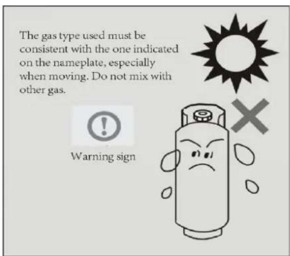

2. Product specifications
2-1.Main technical parameters of the product
Item
HIC-763CF-S
Applicable gas
liquefied petroleum gas
Applicable area
Nation-wide
Rated voltage
DC 3V
Product weight 11.2/12.9kg
Rated
Pressure Liquefied petroleum gas
2800 Pa
Liquefied petroleum gas 6.5KW
Heat efficiency
63%
CO / CO _2 ≤ 0.02
Design dimensions 760mm(L)X450mm(W)X28mm(H)
Electronic-pulse ignition YES
Demountable burner YES
Fully-enclosed panel YES
2-2. Unique features and technical description
Model:HIC-763CF-S

natural_image
Technical line drawing of a mechanical assembly with labeled components (no text or symbols present)Name of Parts
1.Bottom
2.Rubber leg
3. Nozzel
4.Pan Support
5.Burner
6/7/8.Knob
9.Tempered Glass Surface

Fig.1.1
| Model | HIC-763CF-S | Gas Pressure | 2800 Pa |
| Unit Dimensions(mm) | 760x450x28 | Gas category | L.P.G. |
| Net Weight | 11.2kg | Total Heat Input | 6.5kW |
| Normal Heat Input | Left: 3.0kW Mid: 1.5kW Right: 2.0kW | ||
2-3. Part Names
External structure
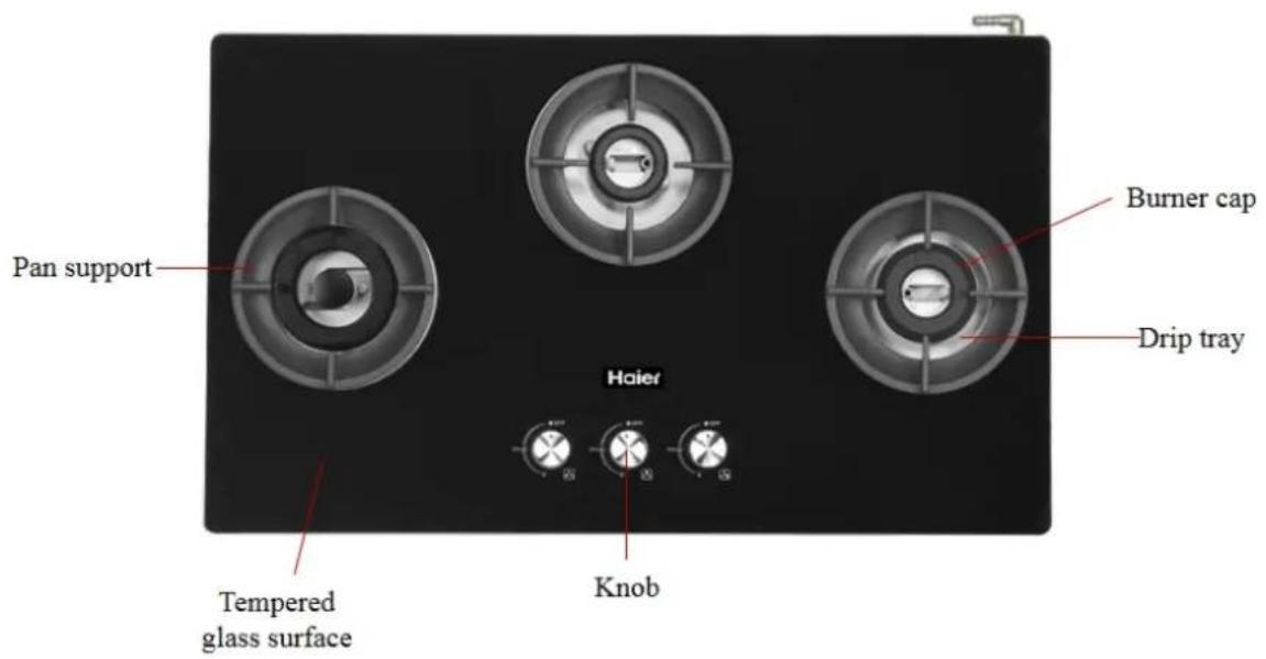
HIC-763CF-S
Note: Due to product improvement, the actual appliance may not be exactly the same as this manual, please refer to the actual product for more details. Sincere apology here.
2-4. Working principle

The gas flows out of the valve nozzle at a certain flow rate under a certain pressure and burner. The gas sucks the primary air by its own energy. In the burner, the gas is mixed primary air and then flows out through the fire cover hole.
Ignition needle discharge generates high-frequency pulse electric spark which ignites gas mixture at the hole, so that it reacts with the surrounding secondary air to burn, forming flame;
- Product installation
3-1. Installation tools
Screw driver

Note: Please refer to relevant installation instructions for specific use occasions.
3-2. Standard installation process

natural_image
Isometric line drawing of a rectangular box with a hand holding a pen, no text or symbols presentCheck the barcode of the product outside the packing box and whether the model and temperament of the machine are the same as purchased by the user.
Before opening the box, check whether the packing box is in good condition, communicate with the user in case of any damage a check the cause of damage when receiving the goods. Before the packing can be opened, the packing must be confirmed to be good.
Place the cooking appliance on a stable countertop or on the ground to ensure stable product placement;
Cut the packing tape on the packing box with the blade and of the packing. Note that the blade does not extend too far into the i of the packing box (it is recommended that the sealing tape doesn't exceed 1mm). Do not use excessive force to prevent damage to the internal product.
After removing the box, remove the foam cover with both hand and then remove the whole machine on the water platform for the operation;
All packaging materials are environmentally friendly and recyclable. Please dispose of these packaging materials in an environmentally friendly manner to maintain a good environment;
Do not allow children to play with plastic film and packaging boxes, which may cause choking accidents;
Accessories check
Please check if the attached accessories are complete
| NO. | Parts name Quantity | Unit |
| 1 | Complete machine of gas cooker 1 | Unit |
| 2 | Operating instructions 1 | Copy |
| 3 | Holder rack 1 | Pc |
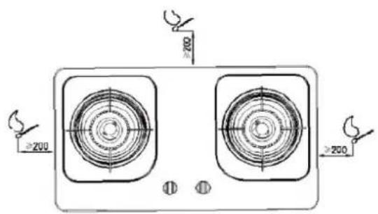
If there are flammable materials around the gas cooker, such as a wooden structure wall, then the distance between the gas cooker and the wooden wall is at least 200mm, and the distance between the cooktop and the suspended ceiling is kept at least 1m;
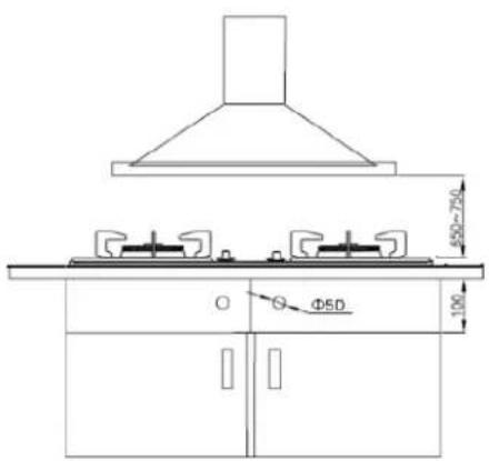
In order to facilitate the operation, ensure the effect of smoke absorption, avoid the impact of high temperature on the hood, the hood of the cooker should be controlled from 650mm-750mm above the height of the hood above the cooker;
In order to ensure the connection of the gas pipe, a space of at least 100 mm height should be reserved below the bottom of the cooker.
1.SOFT PIPE CONNECTION
- Please use a soft pipe connector (see picture 1), and a special gas pipe to connect.
- The hose must be inserted to the red mark of the soft pipe and fixed with a clamp. The length of the pipe should be less than 150cm .
- When the hose is connected with the soft pipe connector, please do not let the air inlet pipe touch any part of the hob or be placed under the hob. Make suer the pipe is not pressed, twisted, or bended by other objects.
- When assembled, please avoid the soft pipe from any force, otherwise, the connector will be damaged. If damage is found during assembling, please stop and contact your local dealer.
- Please change the soft pipe every year.
WARNING:
PLEASE DO NOT USE A HOSE WITH POOR QUALITY OR OLE IN CASE OF GAS LEAKAGE, POISONING OR FIRE HAZARD.
2. HARD PIPE CONNECTION
- For gas hob designed to use a spiral connector(see picture 2), please use spiral connect. It can also be connected with hard pipe or metal soft pipe.
- Please use a sealing pad when connecting, twist it tight with a spanner and hold the hexagonal nut of the connector. Avoid damage of the hob.
- If you need to assemble a soft pipe connector with the spiral one, please follow the indication of the hard pipe connecting method, and avoid damage to the connector and plastic pad.

Air inlet connector
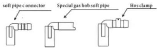
See picture 1

see picture 2
Air inlet connector
3-3. Test machine after installation
Ignition tester
Open the main air source, press the knob to discharge. At the same turn the knob counterclockwise by approximately 90 degrees so that the enters the interior of the cooker and burns to form a flame at the fire.
After the flame is ignited, it is required to be delivered to each fire within 4 seconds;
Observe if the flame can be properly ignited and if there is a sudden flame and there is a phenomenon of ignition noise (detonation). If a deflagration occurs, check whether the gas pressure meets the rated pressure of the cooker. If the pressure is stable or there is a large difference from the rated pressure, contact the gas company for gas circuit perfection (Note: Rated pressure of liquefied gas: 2800Pa; Rated pressure of natural gas: 2000Pa);
Keep pressing the knob for 3-5 seconds and let go. The flame should continue to burn normally without any flameout.
Turn the switch to the minimum flame state for combustion. The flame should be able to burn normally without flameout.
Repeat 10 ignition operations. It should be ensured that there are 8 or more ignitions and 2 consecutive failures cannot be made.
Flame regulation performance tester
When the cooker is in normal combustion, turn the knob to adjust the and observe the change of flame at different angles;
Turn large fire to small fire and small fire to large fire as an adjustment the above cycle for 10 times. The flame change should be normal and no occur.
If there is a related combustion failure, the details of the treatment are troubleshooting instructions.
3-4. Product operation
Use precautions

natural_image
Simple line drawing of a table with two machines and a window, no text or symbols present.With the consent of the user, the V-bottom p and pan will be placed on the holder rack. The base pan has to be stable.
After the pot is in the natural state on the holder rack, pour about 500g of water into it and no water flows out.
Then place the pan in a horizontal position and the pan should not slide automatically and cause the water to flow out.
Note: For V-bottom pot, if there is a phenomenon that interferes with the fire cover when it is placed directly on the holder rack, take out the small rack and place it on the holder rack before verifying base pan.
Precautions for users:
When using, do not allow the product to be exposed to strong winds (for example, if the strong wind from outside the window directly blows the flame), this will affect the normal working conditions of the combustion or even work.
Remind the user to stay cautious for overheating of frying pan when using vegetable oil or animal fat oil for food cooking. When cooking food with such grease, do not leave the food in the pan and leave it alone;
During the training, in case of burning due to the high oil temperature, immediately cover the fire with a large area of metal such as iron cover to cut off the air for combustion, and then close the indoor gas valve. Don't use water to extinguish the fire to prevent accidents;
Close the gas valve on the indoor duct after using the cooker, or before going out or going to bed;
When you need to remove the pan for a short time, switch the burner to a small fire position. In this way, the risk of bu can be reduced even if other operations are performed near the cooker, and gas can be saved and pollution can be reduced.

flowchart
graph TD
    A["Open gas source"] --> B["Press valve for 3-5 seconds"]
    B --> C["Turn knob counterclockwise"]
    C --> D["Adjust fire power"]
    D --> E["Shut down, close gas source, clean cooker"]
    F["Image: Open gas source"] --> G["Image: Press valve for 3-5 seconds"]
    G --> H["Image: Turn knob counterclockwise"]
    H --> I["Image: Adjust fire power"]
    I --> J["Shut down, close gas source, clean cooker"]
Regular operation process diagram

flowchart
graph TD
    A["1 Open indoor gas main valve"] --> B["2 When igniting, turn the knob down to the end and turn it counterclockwise to the horizontal position (large fire burning state). After the fire hole flames are all lit, continue press for 3-5 seconds. After the flameout protection starts, you can release the hand; if the flame is out when you let go, turn the knob clockwise to the off position, and repeat the above ignition operation."]
    B --> C["3 Adjust the fire power"]
    C --> D["4 Turn the knob clockwise to the vertical "OFF" position to turn off the gas cooker"]
    D --> E["5 After the use of gas cooker, please be sure to close the indoor gas main valve"]
    E --> F["6 Small fire Medium fire Large fire Turn off fire"]
Fire adjustment
GAS BURNERS
Gas flow to the burners is adjusted by turning the knobs(illustrated in fig. 2.1)
Turning the knob, so that the indicator line points to the symbols printed on the panel, achieves the following functions:

- symbol ●OFF closed valve
- symbol ON maximum aperture or flow
-
symbol ⚙ minimum aperture or flow
-
The maximum aperture position permits rapid boiling of liquids, whereas the minimum aperture position allows slower warming of food or maintaining boiling conditions of liquids.
- To reduce the gas flow to minimum, rotate the knob further anticlockwise to point the indicator towards the small flame symbol.
- Other operating adjustments can be achieved by positioning the indicator between the maximum and minimum aperture positions, and never between the maximum aperture and closed positions.
Caution!
Do not cover the hob with aluminum foils.
IMPORTANT: To turn the control knob from the closed position "●OFF" to the maximum aperture position "ON", first press in the knob and then turn it anti-clockwise.
N.B. When the cook top is not being used, set the gas knobs to their closed positions and also close the cock valve on the gas bottle or the main gas supply line.
Caution!
The cooking hob becomes very hot during operation.
Keep children well out of reach.
3-5. Cleaning and maintenance
After installation, the installer should remind the user to pay attention to the following matters maintenance:

Cooktop cleaning and maintenance

Fire cover cleaning and maintenance

natural_image
Illustration of three hands performing a manual task with a tool, no text or symbols present

natural_image
Illustration of a hand using a tool to press or install a component on a tray (no text or symbols visible)
Recommended maintenance
frequency
Before cleaning the gas cooker, the indoor gas valve must be cut off and the gas cooker has cooled. Do not disassemble the safety devices and airtight parts of gas cookers during the cleaning process;
Do not use acidic materials (lemonade, vinegar, etc.) to scrub enamel surfaces (eg, holder rack, etc.);
Please use soft gauze and soapy water (or stainless steel special cleaning agent) to clean and maintain the cooker board;
Do not clean the board with a granular detergent (scrub powder) or steel wool. This can cause scratches on the surface of the cooker.
For long-term use, there will be oil pollution inside the fire cover. As shown in the figure on the left, the fire cover can disassembled without any tools, and the oil inside the fire cover can be cleaned easily and simply;
When dismantling or installing the fire cover, avoid hard objects from colliding with the ignition needle to prevent the needle from being damaged and affecting the use of the cooke
After cleaning and maintenance, place the fire cover in place (for details, see 3-4 "Inspection of parts in place");
In the use process, if you find that the flame is uneven or there no flame in the individual fire holes, after the fire cover cools, remo the fire cover in time and clean the dirt and carbon deposit in the hole with iron brush and steel needle. Do not wipe the inorganic water-resistant coating on the burner surface with a hard object. This will cause damage to the black surface that cannot be repaired;
Wipe the discharge end of the ignition needle in time to prevent the dirt from attaching to the surface and affecting the ignition performance.
4. Maintenance equipment
Cross screwdriver

Used for disassembly of the relevant cruciform slot screw;
Screw size is M5;
Used for loading and unloading nozzles;
Used for the fixation and disassembly of the pipe clamp;
U-tube manometer

Used for testing of gas;
Used for gas pressure testing;
Require a measurement range of 0Pa-10000Pa;
Accessories include: airbags, air tube;
Note: Refer to the relevant maintenance instructions for the specific usage of the above tools and equipn
- Main parts display and parameter function table(Photos to be provided lat
HIC-763CF-S
6. Disassembly guide
6-1. Preparation before maintenance
Consulting for fault
Before troubleshooting, please ask the consumer about the symptoms. According to the user's failure symptoms, determine which component may be broken.
Repair tool
Please prepare tools according to the repair tools required by Article 4;
Preparation of spare p
According to the user's fault description, determine which component may be broken, and prepare corresponding spare parts;
Pre-judgement of fault
| Fault | Possible cause | Spare part | Tool |
| Ignition failure | Dead battery, broken pulser ignition needle, or microswit locked nozzle | Battery, pulser, ignition needle microswitch, nozzle | Screwdriver, multimeter |
| No discharge of ignition needlin | Broken ignition needle, puls | Ignition needle, pulser | Screwdriver, multimeter |
| No ignition | Broken pulser | Pulser | Screwdriver, multimeter No ignition |
| Broken ignition needle | ignition needle | Screwdriver, clamp |
6-2. Disassembly and assembly of main (photos to be provided after production)
6-3. Internal wiring instructions (photos to be provided after production)
The whole wiring diagram is shown in figure above
- The two power supply wiring of the pulse generator are red-wire battery box positive electrode and black-wire battery box negative electrode respectively.
- The ignition needle of the left and right burner is firmly connected with the left and right to the pulser respectively.
- The black wire of the pulser is the grounding terminal line (shown in Fig.), and is fixed with body through screws.
- The yellow line of the pulser is 4.8 inserted and connected with the left ignition micro swite
- The pulser green line 4.8 inserts the right ignition micro switch.
- The thermocouple silver thread is fixed to the valve body by screws.
6-4. Change temperament description
Changing temperament operation process

flowchart
graph TD
    A["Phone calls to ask users what kind of temperamer to change, and apply for spare parts according to user feedback."] --> B["Change the door and shut down the gas source."]
    B --> C["Remove the fire cover and the retaining ring"]
    C --> D["Open the stove"]
Implement change of temperament, prepare spare parts and tools, and ensure "once"
Close the gas source and prevent gas leakage.
This model needs replacing the complete valve body when changing temperament.
When the liquefied gas is replaced with natural gas, there is no need to replace the fire cover.
7. Detection
7-1. Safety precautions
When troubleshooting, pay attention to avoid gas leaks;
Switch off other appliances that are in use to prevent the risk of gas leaks;
7-2. Installation status confirmation
| Standard installation status confirmation table | |||
| No. | Item | Standard installation requirements | Whether it conforms to requirements |
| 1 | Gas type | The gas type of the machine is the same as the user's gas type (for products with changed gas type, whether the valve body is correct after starting up) | ☐YES ☐NO |
| 2 | Gas connection | Use hose with inner diameter Φ 9.5mm | ☐YES ☐NO |
| 3 | The gas hose is inserted into the red line on the universal air intake connector | ☐YES ☐NO | |
| 4 | Hose and cooker inlet joints are firmly fixed with pipe clamp | ☐YES ☐NO | |
| 5 | Apply glue at the transition between the pipe clamp and hoses, hoses and cooker joints. | ☐YES ☐NO | |
| 6 | Whether the glue is peeled or misplaced | ☐YES ☐NO | |
| 7 | Fire cover | Fire cover is installed in place | ☐YES ☐NO |
8. Troubleshooting and handling
8-1. Failure caused by abnormal operation
| Symptoms | Telephone service guide |
| Failure needle ignition |  |
| Flameout after letting go(unstable fire) | 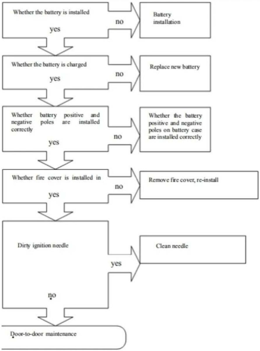 |
| Symptoms | Telephone service guide |
| Failed or hard pulse ignition |  |
8-2. Fault diagnosis and repair
Note
■ Internal wiring must be installed correctly.
■ After the maintenance is completed, perform gas leak detection.
| Fault diagnosis and maintenance | |
| Failed ignition |

flowchart
graph TD
    A["Fault diagnosis and maintenance"] --> B["Press valve body for less than 5 seconds, fail to heat thermocouple. Safety protection fails to function"]
    B -->|yes| C["After successful ignition, press valve for 5 seconds"]
    B -->|no| D["Fire hole is plugged and fire fails to reach thermocouple"]
    D -->|yes| E["Clean fire hole"]
    D -->|no| F["Dirty thermocouple"]
    F -->|yes| G["Loose connection of thermocouple and solenoid valve"]
    F -->|no| H["Re-plug to make it firm"]
    G --> I["Fire thermocouple for 10 seconds, turn multi-meter level to mV level and connect the two probes of multi-meter with two connectors of thermocouple. The measured thermocouple's starting power should be higher than 40mV"]
    H --> J["Broken thermocouple"]
    J -->|yes| K["Replace thermocouple, refer to valve body disassembly operation guide"]
    J -->|no| L["Broken solenoid valve"]
    L -->|yes| M["Replace valve body Refer to disassembly operation guide"]
    L -->|no| N["Connect solenoid valve, regulated DC power supply, milliammeter to loop and adjust regulated DC power supply to detect attracting current and detaching current of solenoid valve. The current range falls between 35mA-100mA."]
| Symptoms | Fault diagnosis and maintenance | ||
| There is a gas flavor when the cooker works well | Leakage | 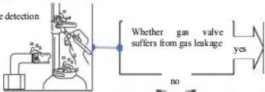 | Reinstall after detection gas circuit. Specific operation refers to cooker gas connection operation requirements. |
| Dissemble valve body assembly according to requirements. Air pipe elbow is connected with one end of U-tubemanometer and put in 10KPa compressedair to the other end. Put the assembly into water, observe whether there is bubble and determine the location ofleakage through the bubble |  | Replace rubber hose. Rubber hose installation refers to cooker gas connection operation | |
 | According to observation, replace parts or re-fix (disassembly process refers to valve body disassembly guide) | ||
- Product breakdown
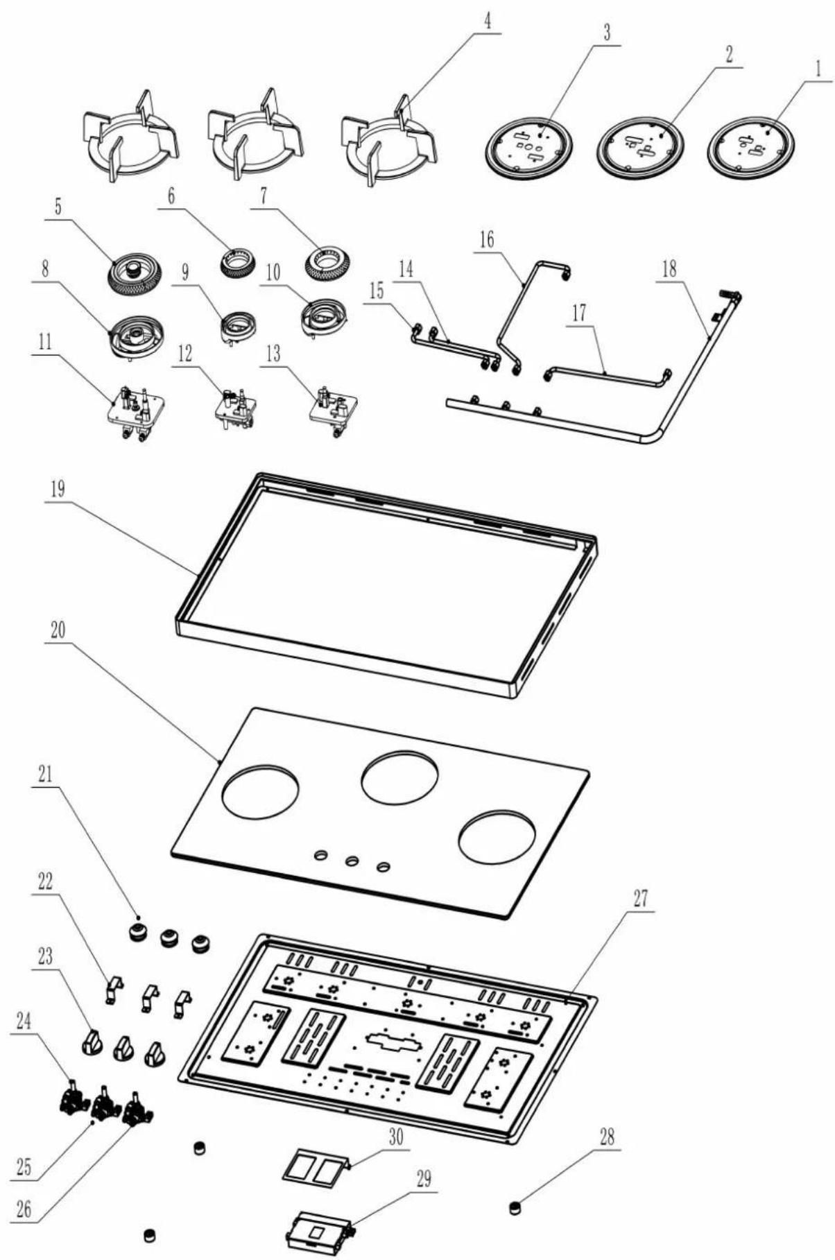
| HIC-763CF-S | |||||
| No. | Special NO. | English Name | Chinese Name | QTY | Remark |
| 1 | 2010202982 | φ70 Drip tray | φ70mm圆水盘 | 1 | |
| 2 | 2010202983 | φ90 Drip tray | φ90mm圆水盘 | 1 | |
| 3 | 2010202984 | φ110 Drip tray | φ110mm圆水盘 | 1 | |
| 4 | 2010204013 | Pan support | 铸铁圆炉架 | 3 | |
| 5 | 2010205078 | φ110 Burner cap with central cap | φ110mm火盖+中心 | 1 | |
| 6 | 2010205076 | φ70 Burner cap | φ70mm火盖 | 1 | |
| 7 | 2010205077 | φ90 Burner cap | φ90mm火盖 | 1 | |
| 8 | 2010202929 | φ110 Burner plate | φ110mm分气盘 | 1 | |
| 9 | 2010202878 | φ70 Burner plate | φ70mm分气盘 | 1 | |
| 10 | 2010202879 | φ90 Burner plate | φ90mm分气盘 | 1 | |
| 11 | 2010205060 | φ110 Mixing tube | φ110mm炉头 | 1 | |
| 12 | 2010205058 | φ70 Mixing tube | φ70mm炉头 | 1 | |
| 13 | 2010205059 | φ90 Mixing tube | φ90mm炉头 | 1 | |
| 14 | 2010202932 | φ110 Outer gas pipe | 110铝管组件(外环) | 1 | |
| 15 | 2010202933 | φ110 Center gas pipe | 110铝管组件(中心) | 1 | |
| 16 | 2010202935 | φ70 Gas pipe | 70铝管组件 | 1 | |
| 17 | 2010204016 | φ90 Gas pipe | 90铝管组件 | 1 | |
| 18 | 2010205062 | Main gas pipe | 气管 | 1 | |
| 19 | 2010205079 | Aluminum frame | 铝合金框 | 1 | |
| 20 | 3070300241 | Temper glass/Glass panel | 玻璃(标准) | 1 | |
| 21 | 3040201056 | Washer of knob | 旋钮套/旋钮孔垫圈 | 3 | |
| 22 | 2010201069 | Bracket | 底板支架 | 3 | |
| 23 | 2010204029 | Knob | 旋钮 | 3 | |
| 24 | 2010205075 | φ110 Gas valve | 110#阀体 | 1 | |
| 25 | 2010205073 | φ70 Gas valve | 70#阀体 | 1 | |
| 26 | 2010205074 | φ90 Gas valve | 90#阀体 | 1 | |
| 27 | 2020201009 | Bottom plate | 底板 | 1 | |
| 28 | 3040204028 | Rubber leg | 炉脚 | 4 | |
| 29 | 2010205055 | Pulse ignitor | 点火脉冲器 | 1 | |
| 30 | 2010201056 | Heat insulation board | 脉冲隔热板 | 1 | |
10. Circuit diagram and program list
10-1. Circuit diagram

10-2. Program table
| Parts status\Operation | Ignition | Normal operation | Turn off fire |
| Valve body microswitch | 0n | 0ff | 0ff |
| Solenoid valve | 0n | 0n | 0n |
| Thermocouple | Off(note, on after 3-5s) | 0n | 0n |
| Flame | Burning | Burning | Flameout |
11. Product inspection
During the maintenance process, service personnel are required to check the components that may be faulty to determine whether they are normal. The main contents include the following
-
Check whether the gas connection pipe of the cooker is installed firmly. Use soapy water perform the leakage test operation. In normal conditions, there should be no bubbles. If bubble appear, there is a leakage phenomenon at the site and maintenance is required;
-
Observe whether the holder rack, fire cover and retainer ring are in place. Check whether seam and deformation of components. If the above situation occurs, maintenance and replacement should be performed according to the situation;
-
Observe whether the fire cover hole is dirty, whether the ignition needle and the thermoco are dirty, and clean up according to the maintenance method.
-
Cut off the gas source of the cooker, put the holder rack and the cleaned fire cover and base on one side, remove the knob, remove the screw fixing the cooktop with a screwdriver remove the cooktop to observe the internal structure;
-
Check if the wire connection of the pulser, thermocouple, and valve body microswitch is to it is loose, re-insert it firmly. If it is broken, replace it again. If the valve body or the no replaced, it must be installed in place (in strict accordance with the specific requirements of disassembly to ensure that the product's air tightness is acceptable;)
-
Check whether the ignition needle is broken or the wire is broken. If there is any problem replace the ignition needle;
-
After dismantling and repairing, arrange the internal wiring of the machine according to the wiring requirements to avoid the heat source and prevent the damp.
- CONTENT
- Project Page number
- Project Page number 34
- Safety precautions (please observe)
- ! Warning
- ! Safety Warning
- Product specifications
- 2-1.Main technical parameters of the product
- 2-2. Unique features and technical description
- Model:HIC-763CF-S
- Name of Parts
- 2-3. Part Names
- External structure
- 2-4. Working principle
- Accessories check
- 1.SOFT PIPE CONNECTION
- WARNING:
- HARD PIPE CONNECTION
- 3-3. Test machine after installation
- 3-4. Product operation
- Precautions for users:
- Fire adjustment
- GAS BURNERS
- 3-5. Cleaning and maintenance
- Maintenance equipment
- Cross screwdriver
- U-tube manometer
- Disassembly guide
- 6-1. Preparation before maintenance
- 6-3. Internal wiring instructions (photos to be provided after production)
- 6-4. Change temperament description
- Changing temperament operation process
- Detection
- 7-1. Safety precautions
- 7-2. Installation status confirmation
- Troubleshooting and handling
- 8-1. Failure caused by abnormal operation
- 8-2. Fault diagnosis and repair
- Circuit diagram and program list
- 10-1. Circuit diagram
- 10-2. Program table
- Product inspection
Brand : HAIER
Model : HIC-763CF-S
Category : Kitchen