Futhrrrr Generator - Synthesizer Endorphin.es - Free user manual and instructions
Find the device manual for free Futhrrrr Generator Endorphin.es in PDF.


| Product Type | Eurorack Synthesizer Module |
| Brand | Endorphin.es |
| Model | Futhrrrr Generator |
| Category | VCO / Sound Generator |
| Width | 6 HP |
| Height | 3U (128.5 mm) |
| Depth | 25 mm (with ribbon cable) |
| Weight | 120 g |
| Power Consumption | +12V: 80 mA, -12V: 30 mA |
| Audio Outputs | 2 (Main, Sub) |
| CV Inputs | 3 (Pitch, FM, Sync) |
| Output Impedance | 1 kΩ |
| Protection | Reverse power protection |
| Operating Temperature | 0°C to 40°C |
| Maintenance | Clean with dry cloth; avoid moisture |
| Safety | Handle with ESD precautions; use only in Eurorack case |
| Spare Parts / Repairability | Contact Endorphin.es for service |
| Manual Language | English (PDF download) |
Frequently Asked Questions - Futhrrrr Generator Endorphin.es
User questions about Futhrrrr Generator Endorphin.es
0 question about this device. Answer the ones you know or ask your own.
Ask a new question about this device
Download the instructions for your Synthesizer in PDF format for free! Find your manual Futhrrrr Generator - Endorphin.es and take your electronic device back in hand. On this page are published all the documents necessary for the use of your device. Futhrrrr Generator by Endorphin.es.
USER MANUAL Futhrrrr Generator Endorphin.es
This page is intentionally left blank.
First things first
RTFM – be so kind and read the manual. It will provide you with the information you need to fully indulge in the module you just purchased – for which we like to thank you.
Enjoy your sound experiences, dear sonic traveller.
Beginning from the product's purchase date a 1-year warranty is guaranteed for each product in case of any manufacturing errors or other functional deficiencies during runtime.
The warranty does not apply in case of:
• damage caused by misuse
- mechanical damage arising from careless treatment (dropping, vigorous shaking, mishandling, etc.)
- damage caused by liquids or powders penetrating the device
- heat damage caused by overexposure to sunlight or heating
• electric damage caused by improper connecting
Visit us:
http://endorphin.es
http://youtube.com/user/TheEndorphines
http://facebook.com/TheEndorphines
Drop us a line:
info@endorphin.es
FURTH BARCELONA, S.L.
VAT ID:ES B66836487
FURTHRRRR GENERATOR OPERATED BY ENDORPHIN.ES
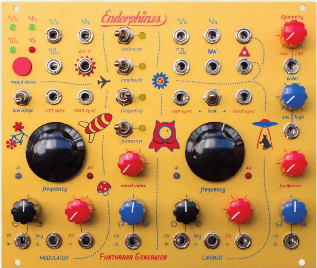
ZE FURZER IS OURZ! – Don Kartofflo
- 30 HP/TE width, up to 1" in depth (super slim & therefore SHUTTLE friendly)
- All analog signal path inspired by & based upon famous westcoast synthesis—a module steeped in the tradition of harmonic generation based on additive synthesis theory
• Multi-turn frequency knobs sweep up to 10 octaves
• Oscillator tuners that simply always work - 2 discrete triangle core oscillators both with hard- (resettable) and soft- (inverting) syncs and selectable 1 or 1.2 V/0ct tracking
- Instant thru-zero linear FM with the STRONG ZERO VCO core update—deep, metallic timbres, entirely new spheres of sounds from light whistles to weird noises
• Together with Terminal or Grand Terminal the FURTHRRRR GENERATOR creates a powerful 2-operator modular FM-synth

INTRO
The main inspiration of the FURTHRRRR GENERATOR routing came from Buchla's Programmable Complex Waveform Generator Model 259, however the FURTHRRRR GENERATOR isn't a clone of it. All circuit parts were carefully developed from scratch, using reliable modern components. Also the module does not put any vactrols to work (which allows audio frequency modulation over every parameter).
The FURTHRRRR GENERATOR is a dual oscillator module with advanced waveshaping and modulation capabilities. It consists of two oscillators (Modulator and Carrier) with the modulation bus (Mood Index) connecting them.
The CARRIER (a.k.a. 'Principal' or 'Slave') oscillator is the beginning of everything.
![graph LR A["MODULATOR OSCILLATOR: (shaping, modulating, or 'Master')"] --> B["mood index"] B --> C["balanced"] B --> D["amplitude"] B --> E["frequency"] B --> F["furthrrr"] B --> G["mood wave select/ ext. input"] H["CARRIER OSCILLATOR: (a.k.a. 'Principal' or 'Slave')"] --> I["mood index cv"] I --> J…](/content/2026/05/1055714/images/d65e3abfc2646c139a5f6437a36485e644ebc86b18aad4ff29e0ebcfaee2d83a.jpg)
It features accurate 1 (or 1.2 user-selectable) volt per octave scaling, two types of synchronization, sine, saw (falling ramp), pulse outputs, white (flat) noise and a dedicated harmonic section. This section is where the magic happens and involves a complex chain of waveshapers with a wavefolder, as well as modulation index bus (Mood Index) with amplitude, balanced, frequency and timbral modulation. Every parameter is voltage controlled and interacts/depends with/on other parameters.
What are harmonics? They are voltages or currents at frequencies that are a multiple of the fundamental frequency. A pure sine wave contains only the one fundamental harmonic. Symmetric waves like a square and a triangle contain only odd harmonics. They are symmetrical above and below their horizontal centerlines. Asymmetric waves like a sawtooth contain both even & odd harmonics.
The harmonic section in Furthrrr Generator operates with 3 knobs/parameters: symmetry, order, furthrrrr (top to bottom)
Here is kind of a starmap to imagine the waveshaping scheme:

The whole scheme is a bit complicated; so don't get frustrated if you don't understand everything the first place. A good way to approach the FURTHRRRR GENERATOR is to understand and bear in mind the following concept:
Forget about the waveforms!
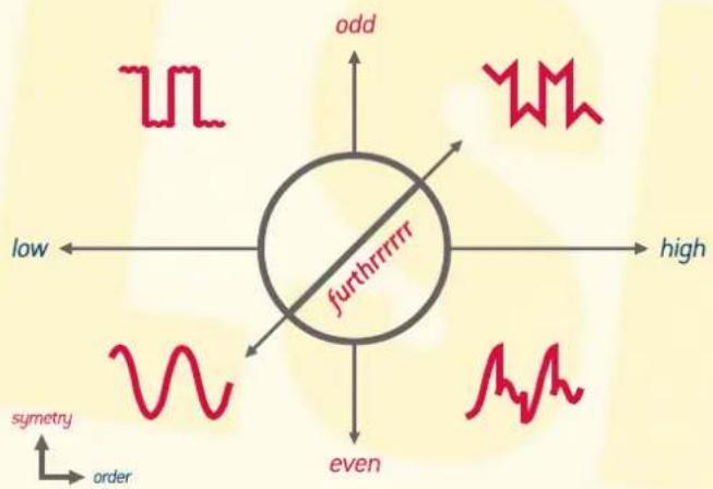
Everything starts with the sine wave: We receive this first fundamental harmonic when all three controls (symmetry, order, furthrrrr) are fully counterclockwise (ccw), we obtain a pure sine wave from the final output (jacks above and below the triangle icon left to the 'symmetry' knob). Tweaking all three controls of the waveshaper section, we can obtain a sort of three-dimensional control over harmonic content.
![graph TD A["PURE SINE: Fundamental Harmonic"] --> B["0"] B --> C["1"] C --> D["0"] D --> E["0"] E --> F["0"] F --> G["0"] G --> H["0"] H --> I["0"] I --> J["0"] J --> K["0"] K --> L["0"] L --> M["0"] M --> N["0"] N --> O["0"] O --> P["0"] P --> Q["0"] Q --> R["0"] R --> S["0"] S --> T["0"] T --> U["…](/content/2026/05/1055714/images/79323a1dfbdb6d13f8ec30a6f0ade95f7662cc5734c91578a80bd988ac164fc2.jpg)
In the analog world, the waveforms are not perfect as in the digital domain. Thus even a pure analog sine wave contains some minor amounts of even & odd harmonics and sometimes that is being considered as what brings the uniqueness and feeling of liveliness to the analog sound.
Therefore tweaking the knobs of the Carrier oscillators' waveshaper will not give you precise settings of the harmonics amounts at the Final output, however they represent a cunning approximation of what is going on in the sound spectrum as upon additive synthesis.
RECREATING the 258 WAVESHAPER.
When 'order' is at the maximum clockwise (cw) position, 'furthrrrr' defines shaping from sine to either saw or square. 'Symmetry' defines shaping between saw and square. So far, we see the behavior of the Buchla model 258 waveshaper.
![graph TD A["pure sine:"] -->|fundamental harmonic| B["none"] A -->|furtherrrrrr| C["(even)"] A -->|1/2 258| D["(odd)"] B -->|symmetry| E["({odd})"] D -->|symmetry| F["({even})"] style A fill:#f9f,stroke:#333 style B fill:#ccf,stroke:#333 style C fill:#cfc,stroke:#333 style D fill:#fcc,stroke:#333](/content/2026/05/1055714/images/9b61207d55c3e2a15f922bbb5c123c1015b53291f0426744605271adafe9768b.jpg)
A pure square wave with 50% duty cycle contains only odd harmonics. Altering its pulse-width will enrich the wave with even harmonics and makes it sound more musical. The 'symmetry' knob also alters the pulse-width of the square wave output of the Carrier oscillator. In full clockwise (odd) position there will be a pure square with 50% of duty cycle from square jack output. However, when cranking the 'symmetry' knob counterclockwise (to even) the pulse duration of the square wave decreases and further in all the way to the left position it becomes a so called 'spike' wave with very short almost 0% duty cycle.
![graph TD A["symmetry"] --> B["1-2% narrow pulse"] B --> C["even"] B --> D["add"] E["CARRIER"] --> F["50% duty cycle pulse"] G["CARRIER"] --> H["50% duty cycle pulse"]](/content/2026/05/1055714/images/19808170e94b392a25d045e5ad598f3a91d4de74f34dcf21a9ea7c5c807d881f.jpg)
The MODULATOR (shaping, modulating, or 'master') oscillator produces sine, saw (falling ramp), and square waves. When the low-range switch is flicked down, the oscillator acts as a Low Frequency Oscillator (LFO LED blinks according to the frequency in this mode and the tuner LEDs shuts off).
Both oscillators can produce a wide range of sounds: the lowest value is nearly 10 cycles per second and the highest is up to 10 kHz. The oscillators are equipped with only one multi-turn potentiometer that sweeps up to 10 octaves or approximately 1 octave per revolution of the knob, if you want to put it in that way. Higher/lower frequencies can be achieved by applying CV, modulations and flicking the low-range switch (lowest frequency of the modulator in low-range mode is around 0.22 Hz/one cycle every 4.55 sec). Every oscillator uses the same inputs one can find in almost every VCO:
- exponential fm DC-coupled input (cv in) with black attenuverter (polarizer) knob,
- direct unattenuated 1v/oct DC-coupled input [key in],
- as well as linear fm AC-coupled input (fm in) with red attenuator input.
![graph TD A["oscillator's frequency knob (10 turns)"] --> B["frequency"] B --> C["cv in"] B --> D["key in"] B --> E["fm in"] C --> F["exponential CV input with attenuverter"] D --> G["unattenuated 1v/oct input"] E --> H["linear fm input with attenuator"] style A fill:#f9f,stroke:#333 style B fill:#cc…](/content/2026/05/1055714/images/571fd491bd55cf4fbb48446e336ff3e0b0c65210207faa0c496578e8ad760b77.jpg)

The hearts of the oscillators are based on a discrete pure analog triangle core. The principles of how every oscillator works may be compared to flushing a toilet. Every time the tank is full of water, it is flushed. The process of refilling with water takes some time—let's suppose the time for flushing and refilling is same. During that continuous flushing/refilling, the water level goes up and down all the time.
It results in a so called 'triangular' waveform.
Your hand when you push the flush knob [hand down] or release it [hand up] is two different states and results in a 'square' waveform.
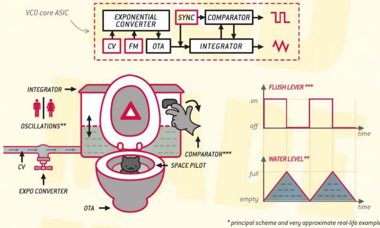
* principal scheme and very approximate real-life example
As alternative to the standard triangle cores provided with the FURTHRRRR GENERATOR by default, we offer the STRONG ZERO VCO Core (http://endorphin.es/endorphin.es--modules.html) replacement for even deeper, metallic sounds at heavy linear frequency modulations. It is a pin-to-pin compatible chip with band-limited triangle and square wave generators.
By using our own integrated circuit technology and producing proprietary encapsulated chips, we achieve great results regarding the oscillators' tracking and stage-ready temperature compensation (frequency stabilization of generator takes only 10 minutes after power-up). This results in 5 octaves of perfect tracking, well-known musically sounding frequency modulation as well as both types of oscillator synchronization: soft and hard


SYNCHRONIZATION is needed in order to eliminate beating (discrepancies in pitch) between two oscillators. Sometimes it is used intentionally to enrich the synchronized oscillators with harmonics (overtones).
The hard sync fully restarts the oscillators' cycle and delivers the results one would expect from a hard-synced oscillator—namely a tearing and ripping harmonic sound. In fact, it enriches all output waveforms with even and odd harmonics in amounts akin to a sawtooth waveform.
When soft sync is applied, it does not restart the waveforms' cycle but changes (inverts) its direction (up to the next half-cycle) and results in a much more complex harmonic saturation.

Both types of synchronization can function independently (Modulator and Carriers synced in different ways) thereby obtaining results that are even more interesting. Keep in mind that applying the same synchronization signal to both soft- and hard-syncs inputs simultaneously will result in hard sync.
Be aware: best audible effect of oscillators' synchronization is when two oscillators (Modulator and Carrier) relate to each other with more or less similar frequencies. When the frequencies differ (e.g. in 4-5 octaves or more), then the Modulator can restart (or change) the direction to the Carrier so fast (or slow), that the Carrier will either simply always restart at the beginning of the cycle and just wouldn't be able to go into oscillation, or restart only once per every thousand cycles, so you will not hear how it is affected.
The 'lock' switch is a pre-routed synchronization in order to sync the Carrier to the Modulator: soft sync is enabled in the left position, hard sync in right position and no sync is applied in the middle position of the switch.
![graph TD A["MODULATOR master clock"] --> B["soft sync from modulator enabled"] B --> C["soft sync ← lock → hard sync"] C --> D["CARRIER slave oscillator"] D --> E["hard sync from modulator enabled"] E --> F["no sync"] F --> G["individual external master-sync (clock) VCO inputs"]](/content/2026/05/1055714/images/51ca853ff7f228130ef551070d1f35fe57c919c78134dacc410b278ba0302d1a.jpg)
MOOD INDEX allows to simultaneously modulate different parts of the Carrier (right side) oscillator with the Modulator (left side). The result of all that modulations are obtained at the final output (the ones with the triangle) jacks. The amount of modulation may be voltage controlled and the 'mood index' can be considered to be a smooth wet/dry (or amount) control for how much modulation is sent to an appropriate destination as selected by the 4 toggle switches located above the red 'mood index' knob. All modulations are bypassed when the 'mood index' knob is turned fully counterclockwise (all the way to the left).
![graph TD A["CARRIER VCO CORE (frequency)"] --> B["CARRIER WAVESHAPERS (furthrrr)"] B --> C["RING MODULATOR (balanced)"] C --> D["FINAL VCA (amplitude)"] D --> E["MOOD INDEX VCA"] E --> F["MODULATOR"] F --> G["mood wave select or ext. in source"] G --> A](/content/2026/05/1055714/images/6b5d5e2240ad8feeb30b1946321b316a2d153365e0a6cfedb6c233b6fa1d46fd.jpg)
© 2013-2017 – Endorphin.es page 6 of 11
With the 'mood wave' button, we choose the modulating waveform (at the top-left of the module). This features an additional random sample & hold source, the rate of which is set by the Modulator (left oscillator) frequency).
An ‘external input’ (ext. in) is also available so that you can inject any signal that you want This powerful option is activated when you select the random source by skipping through the modulation waves by pressing the ‘mood wave’ button until the red LED lights up and a signal is applied into the ‘ext. in’ jack (the one with the flower). This will then replace the sample & hold signal.
The following is a list of destinations of the 'mood index' bus with additional information about what is going on. The Modulator can simultaneously, or separately modulate the Carrier oscillator. A selected destination will receive the modulation from the 'mood index' bus, if its corresponding LED at the switch is
![graph TD A["Green dot"] --> B["Waveform"] C["Red dot"] --> D["Waveform"] E["Green dot"] --> F["Waveform"] G["Red dot"] --> H["Waveform"] I["Green dot"] --> J["Waveform"] K["Green dot"] --> L["Waveform"] M["Green dot"] --> N["Waveform"] O["Green dot"] --> P["Waveform"] Q["Green dot"] --> R["Waveform"…](/content/2026/05/1055714/images/2e8443bb95ee37c9e99e929b1b0ea21f65e85a229f3043554d672944f1cea5d6.jpg)
AMPLITUDE MODULATION is when Modulator controls the amplitude of the Carrier at its final outputs. Audio rate a.m. will result in artifacts that somewhat resemble balanced modulation (ring modulation). Sub-audio rate a.m. results in tremolo at the Carriers' final outputs (triangle).

BALANCED MODULATION is multiplying the signals of the Modulator and the Carrier. Sometimes it is referred to as 'ring modulation'. The mood index control dictates the amount of balanced modulation being applied to the Carrier. Balanced modulation produces the sum and difference of the frequencies (harmonics) present in each waveform—new harmonics (intermodulations) are obtained. Sometimes it may be considered as thru-zero amplitude modulation, because at the moment when Modulator goes below zero, the Carrier wave—besides amplitude control—also inverts its direction.
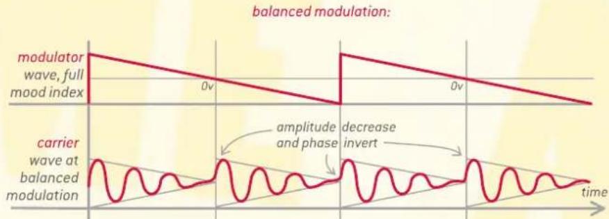
FREQUENCY MODULATION defines the level of modulation of the Carrier oscillators' pitch. This is often referred to by its initials 'f.m.'. This can be viewed as analog two-operator fm-synthesis. Frequency modulation can be switched between linear or exponential via a jumper on the back of the PCB [see the last chapter of that manual].

Sub-audio rate f.m. results in a vibrato at the Carriers' outputs (usually exponential f.m.), while audio rate modulation (usually linear f.m.) may bring entirely different results in obtaining new timbres, bells, whistles or metallic sounds.
Tipp: The difference between linear and exponential modulation explained in more details in Strong Zero VCO core manual:
http://endorphin.es/assets/endorphin.es_strong_zero_core_manual.pdf
The main idea is that at high modulation amounts (index) the pitch of the Carrier remains stable. In the analog world is difficult to obtain a stable linear f.m., that's why within heavy linear frequency modulation the pitch of the analog VCO core will shift—but will remain stable with the digital Strong Zero core.
Also, in terms of frequency modulation (also covered in the Strong Zero manual) is the frequency ratio between Modulator and Carrier. Frequency ratio 1:1 (when Modulator and Carrier are at the same frequency) will result in even harmonics. Ratio 1:2
[Carriers' frequency twice higher than the Modulators'] will result in odd harmonics.
Afterwards non-integer ratio values will result in generation of in-harmonic content—this is useful for synthesizing atonal timbres.
There is a pre-routed connection from the Carrier final output into the Modulator's linear f.m. input jack, for producing quick cross-modulation without the use of extra patch cables. When Modulators' 'fm in' knob is fully counter-clockwise, then no modulation is applied. That feature is disconnected by plugging a cable into the 'fm in' jack.
![graph TD A["Modulator"] -->|fm in| B["Internal pre-routing to switched CV IN jack"] B --> C["CARRIER"] style A fill:#f9f,stroke:#333 style C fill:#ccf,stroke:#333](/content/2026/05/1055714/images/189ae0363093e1f326d3a5ac60dbcb376bcef2643cab5e5850f5b317a9fce64e.jpg)
FURTHRRRR MODULATION
Ah, the good stuff! This produces the modulation of the 'furthrrrrrr' control (right side of the module in the waveshaper section). This will result in either more or less waveshaping. The harmonics added by this process are among the richest & most dramatic timbral variations in synthesis. C'est la 'Raison d'être' de notre belle bête!
THE SENSE OF FURTHRRRR TRANSFORMATION

LOONEY TUNERS are visible via two LEDs on each side of the multi-turn frequency knobs of the oscillators. They are digital tuners which continuously scan the frequency of each oscillator and compare it with the frequency (multiples of the A-notes) within the range or hearing and lower: 13.75 Hz, 27.5 Hz, 55 Hz,..., 440 Hz and up to 14,080 Hz.
When the oscillators' frequency is lower than the nearest A-note then left LED lights.
When it's higher than the nearest A-note, the right LED lights. When the frequency lands exactly upon any A-note, both LEDs will light. Now what could possibly be simpler and more performance-friendly than that?
![graph TD A["perfect A note"] --> B["higher than nearest A"] B --> C["lower than nearest A"] C --> D["perfect A note"] subgraph Frequency Range E["110 Hz"] --> F["220 Hz"] G["440 Hz"] --> H["880 Hz"] end style A fill:#f9f,stroke:#333 style B fill:#ccf,stroke:#333 style C fill:#cfc,stroke:#333 style D…](/content/2026/05/1055714/images/e2f3fd89ad742f2c6309a6896dc0dc6d2ff4ad9eeb97a85259c530cb2a9557f4.jpg)
© 2013-2017 – Endorphin.es page 8 of 11
The tuners in the Furthrrr Generator only represent a visual pitch reference point and do not affect the pitch or the audio path in any way. Tuning is now fun and does not require any live monitoring or listening at all—you can tune your oscillators before or during the performance very quickly.
Note: Frequency modulation applied to the oscillator will alter its tune correspondingly and the resulting pitch will be varying in time. In that case the Looney Tuners will go mad.
We advise you to trust your ears and enjoy your Endorphin.es!
Special thanks go to Marko Ciciliani, Kent Iverson and Stefan Leberfinger for invaluable contribution and sincere help.
TRIMMING & SERVICING. The module comes factory tuned to 1V/oct scale and is trimmed before shipping. However, sometimes you may want to make some calibrations. On the picture below you can see the backside of the module with the following controls:

- DOEPFER A-100 BUS IDC-CONNECTOR. We advise that you use the supplied 16-pin ribbon cable. Please ensure that the red stripe of the cable (the top pair of red/orange pins/wires) is connected to the negative -12V rail when plugging the cable to your power distribution board. If the ribbon cable is connected backwards, the module might be harmed.
Hint: Please ensure twice before connecting since this is not covered under warranty.
-
VCO CORES OF OSCILLATORS. In the picture above, the left core is the Carrier oscillator and the right is the Modulator. Please don't remove them without any necessity except you change the stock VCO core to a Strong Zero VCO core. The VCO core replacement procedure is described in the Strong Zero VCO core manual.
-
VOLT PER OCTAVE SCALE TRIMMERS & JUMPERS FOR 1.2V/OCT SCALE. If you need 1.2V/oct scaling, just install the jumper to the appropriate oscillator. If you stay with 1V/oct scaling—don't do anything. However the scaling may need to be trimmed in any case after changing the tracking mode.
The Volt per octave trimming procedure never was so easy as now. Just play an infinite looping sequence of two consequent same notes from 4-5 different octaves (we recommend A-notes as you then can use the Looney Tuners) and determine whether the subsequent pitches are deviating from the preceding lower notes.
For playing same the notes in consequent octaves you will need a MIDI to CV converter. It is convenient to use the Endorphin.es Shuttle Control. With the new Cargo 3 firmware you can play consequent notes right from Web MIDI calibrator
https://www.endorphin.es/cargo3/calibration.php by hitting the 'Play test' button.
With an ordinary flat screwdriver you make small turns in clockwise or counterclockwise directions of the blue V/oct trimmers and observe the tuners while fine-tuning the big frequency knob of a certain oscillator. That trimmers can make 25 turns, however try to make small half turns to fit into desired scale. Clock-wise rotation of the trimmer narrows the scale of the oscillator, while counterclockwise rotation widens the scale. The result of your trimming process for each oscillator should be when every played note in octave will be in scale (both LEDs will light up). The tracking is considered as 'trimmed' when you obtain up to 5 octaves of stable tune. For a very precise trim, we advise to use laboratory frequency counters.

FURTHRRRR GENERATOR SHUTTLE CONTROL
![graph TD A["C3 note (0v)"] --> B["C4 note (1v)"] B --> C["C5 note (2v)"] C --> D["C6 note (3v)"] D --> E["upcoming notes deviate to the lower pitch from the tuned octaves"] E --> F["proper scale"] F --> G["C6 note (3v)"] G --> H["C5 note (2v)"] H --> I["C4 note (1v)"] I --> J["C3 note (0v)"] style A…](/content/2026/05/1055714/images/3cf672fa5ac8b440744ea1e4322b129842297d8e7cf486da2cacb6914e2a23c8.jpg)

- MOOD INDEX FREQUENCY MODULATION TYPE. That jumper on the backside of the PCB defines whether it will be linear (or just called ordinary f.m., AC-coupled) or exponential (c.v./pitch, DC-coupled) frequency modulation.
- ON-THE-BUS or OFF-THE-BUS JUMPERS. When the appropriate jumper is installed, the CV from the 13/14th pins of the Doepfer A-100 system bus (Bus CV) goes directly to the exponential CV input (key in) of the appropriate oscillator. However, the connection is conveniently temporarily broken when a plug is inserted into the appropriate 'key in' jack of either Modulator or Carrier.
- INITIAL SENSIVITY OF FURTHRRRR CONTROL. When the symmetry, order and furthrrrr knobs are fully counterclockwise and no modulation is applied to waveshaper, there should be a sine wave at the final outputs (triangle) of the module. If necessary, adjust the little trimmer so that the sine wave will have the maximum amplitude (approx. up to +/-5V or 10Vpp) without starting to fold. Use your ears if you don't have an oscilloscope.
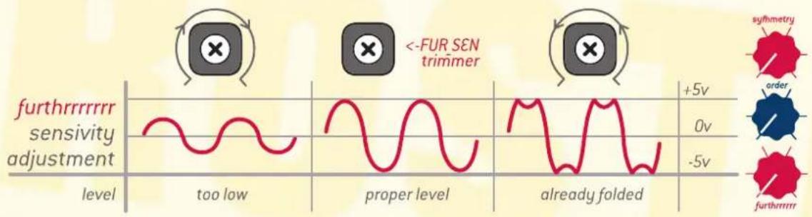
- FURTHRRRR CONTROL DC-SYMMETRY OFFSET. Adjust carefully and only when the sine wave at the final outputs (triangle) of the Carrier oscillator begins to fold non-symmetrically when starting to rotate furthrrrr control while symmetry and order controls are fully counterclockwise.

- NOISE LEVEL ADJUSTMENT. Furthrrr Generators after S/N 474 have special trimmer to adjust the level of the internal noise-generator of the Carrier. That noise is afterwards sampled with the frequency of the Modulator to create a 'sample and hold' waveform. It is important to keep that waveform at a level from -5v to +5v. Lower or higher levels may alter the sample and hold output correspondingly. Furthrrr Generators before S/N 474 have a fixed and already pre-trimmed noise level.


Enjoy your Furthrrrr and never forget —The Endorphin.es will make you happy!


Brand : Endorphin.es
Model : Futhrrrr Generator
Category : Synthesizer