
40932 - Wall mount DA-LITE - Free user manual and instructions
Find the device manual for free 40932 DA-LITE in PDF.

| Product Type | Wall Mount |
| Brand | Da-Lite |
| Model | 40932 |
| Material | Steel |
| Color | Black |
| Maximum Load Capacity | 50 lbs (22.7 kg) |
| Compatible Mounting Pattern | VESA 100x100 / 200x200 |
| Mounting Hole Pattern | Universal with adapter plates |
| Adjustment Type | Fixed with leveling |
| Distance from Wall | Approximately 2.0 inches (5.1 cm) |
| Dimensions (W x H x D) | 15.5 x 9.0 x 2.5 inches (39.4 x 22.9 x 6.4 cm) |
| Weight | 3.5 lbs (1.6 kg) |
| Installation Type | Wall-mounted |
| Included Hardware | Screws, anchors, leveling tool |
| Compliance | UL listed |
| Warranty | Limited lifetime |
| Country of Origin | USA |
| Recommended Use | Projector or screen mounting |
| Care Instructions | Wipe with a dry cloth; avoid harsh chemicals |
Frequently Asked Questions - 40932 DA-LITE
User questions about 40932 DA-LITE
0 question about this device. Answer the ones you know or ask your own.
Ask a new question about this device
Download the instructions for your Wall mount in PDF format for free! Find your manual 40932 - DA-LITE and take your electronic device back in hand. On this page are published all the documents necessary for the use of your device. 40932 by DA-LITE.
USER MANUAL 40932 DA-LITE
natural_image
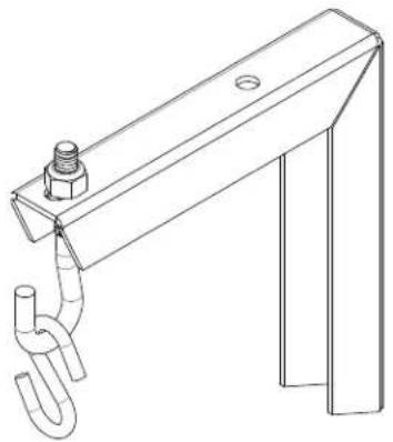
Technical line drawing of a mechanical clamp or bracket with a threaded hook and bolt (no text or symbols)INSTRUCTION BOOK FOR
No. 6 Sheet Metal Wall
Brackets
Disclaimer
Milestone and its affiliated corporations and subsidiaries (collectively "Milestone"), intend to make this manual accurate and complete. However, Milestone makes no claim that the information contained herein covers all details, conditions or variations, nor does it provide for every possible contingency in connection with the installation or use of this subject to change without notice or obligation of any kind. Milestone makes no representation of warranty, expressed or implied, regarding the information contained herein. Milestone assumes no responsibility for accuracy, completeness or sufficiency of the information contained in this document.
Da-Lite ^® is a registered trademark of Milestone AV Technologies. All rights reserved.
Important Safety Instructions
WARNING: A WARNING alerts you to the possibility of serious injury or death if you do not follow the instructions.
CAUTION: A CAUTION alerts you to the possibility of damage or destruction of equipment if you do not follow the corresponding instructions.
WARNING: Failure to read, thoroughly understand, and follow all instructions can result in serious personal injury, damage to equipment, or voiding of factory warranty! It is the installer's responsibility to make sure all components are properly assembled and installed using the instructions provided.
WARNING: Exceeding the weight capacity can result in serious personal injury or damage to equipment! It is the installer's responsibility to make sure the weight of all components does not exceed 140 lbs. (63.50 kg) or 70 lbs (31.75 kg) per bracket.
WARNING: Use this mounting system only for its intended use as described in these instructions. Do not use attachments not recommended by the manufacturer.
WARNING: Never mount these brackets if they are damaged. Return the brackets for replacement.
⚠ WARNING: Do not use this product outdoors.
IMPORTANT NOTE: The No. 6 wall brackets are designed to be mounted to an 8" bare concrete wall, 8" x 8" x 16" bare concrete block wall, or a 2" x 4" wood studs (16" on center) wall covered by drywall with a maximum thickness of 5/8".
Save These Instructions
natural_image
Technical line drawing of a mechanical bracket with a U-shaped pipe and bolt (no text or symbols)

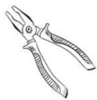
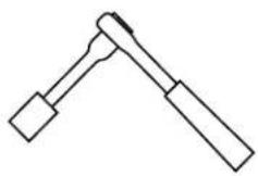
Pliers
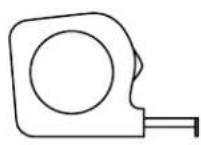
Tape Measure
natural_image
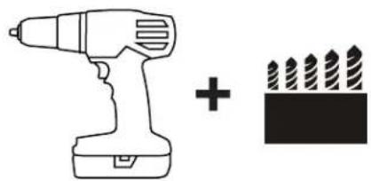
Simple line drawing of a drill bit and a pencil icon (no text or symbols)3/16" (wood) 5/16" (concrete)
7/16" Socket (wood)

2 Phillips Screwdriver (concrete)
natural_image
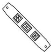
Simple line drawing of a rectangular object with three diamond-shaped cutouts and two small holes (no text or symbols)4 ft. Level
Parts

natural_image
Technical line drawing of a metal bracket with two holes and support legs (no text or symbols)(2) Metal Wall Brackets (2) 5/16" - 18 Open Eye Bolts
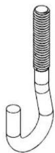

(2) 5/16" - 18 Nylon Locking Hex Nuts
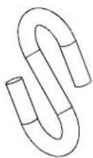

(2) 5/16" - 18 Hex Nuts (2) "S" Hooks
Installation
The No. 6 wall brackets are designed to be mounted an 8" bare concrete block wall, 8" x 8" x 16" bare concrete block wall, or a 2" x 4" wood studs (16" on center) wall covered by drywall with a maximum thickness of 5/8".
Locate Mounting Site
WARNING: IMPROPER INSTALLATION CAN LEAD TO SCREEN FALLING CAUSING SEVERE PERSONAL INJURY OR DAMAGE TO EQUIPMENT! It is the installer's responsibility to make sure the weight of all components does not exceed 140 lbs. (63.50 kg) or 70 lbs. (31.75 kg) per bracket.
Proceed to either the Installing to a Wood Stud Wall section or the Installing to a Concrete Wall section.
Installing to a Wood Stud Wall
NOTE: Depending on the overall length of your screen case, it may not be able to be mounted to a stud wall. Each end of the screen case must be within 1" of the center of a wall stud in order to properly hang from the wall bracket.
- Determine how far up the wall to hang screen.
- Mark wall for center of screen housing.
- Measure up 2" (50.80mm) from the first mark and make a second mark.
- Locate the (2) wall studs closest to the ends of the case. (See Figure 1).
- Using a level, mark the wall on each stud using the second mark from Step 3.
WARNING: ELECTRICAL SHOCK HAZARD! CUTTING OR DRILLING INTO ELECTRICAL CORDS OR CABLES CAN CAUSE DEATH OR SERIOUS PERSONAL INJURY! Always make certain area behind mounting surface is free of electrical wires and cables before drilling or installing fasteners.

Figure 1
WARNING: EXPLOSION AND FIRE HAZARD! CUTTING OR DRILLING INTO GAS PLUMBING CAN CAUSE DEATH OR SERIOUS PERSONAL INJURY! Always make certain area behind mounting surface is free of gas, water, waste, or any other plumbing before cutting, drilling or installing fasteners.
- Drill one 3/16" (4.8mm) pilot hole at each wall stud marking.
- Using one 1/4" x 1-1/2" lag bolt (not provided) and 1/4" flat washer (not provided) attach bracket to wall using top mounting hole. (See Figure 2)
IMPORTANT NOTE: Lag bolt must be secured into a wall stud.
- Drill one 3/16" hole (4.8mm) pilot hole through bottom bracket hole.
- Using one 1/4" x 1-1/2" lag bolt (not provided) and 1/4" flat washer (not provided) fasten through bottom hole of bracket (See Figure 3)
IMPORTANT NOTE: Lag bolt must be secured into a wall stud.
- Repeat steps 6-9 for second bracket.
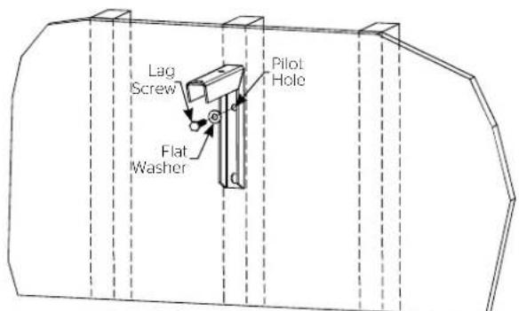
Figure 2
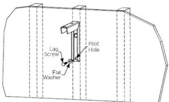
Figure 3
Installing to a Concrete Wall
- Determine how far up the wall to hang screen.
- Mark wall for center of screen housing.
- Measure up 2" (50.80mm) from the marking and make a mark.
- Measure the overall length of your screen case and divide by two. This will give you the distance from your center mark to each bracket. Drill a 1/2" hole through hollow part of cinder block. (See Figure 4)
IMPORTANT NOTE: If the holes are not going to fall on the hollow portion of the cinder block, the screen position will need adjusted.
- Measure down 3-1/2" (88.90mm) from previous drilled hole and drill another 1/2" hole. (See Figure 4)
- Insert two 1/4-20 Snap Togglers (not supplied) into concrete wall. (See Figure 4)
- Using two 1/4-20 x 2" long machine screws (not provided) and 1/4" flat washers (not provided) attach bracket to wall using top and bottom mounting holes. (See Figure 5)
- Repeat steps 4-7 for second bracket.

Figure 4

natural_image
Technical line drawing of a mechanical clamp or bracket assembly inside a circular frame (no text or symbols)Figure 5
Assembly
- Thread hex nut onto 5/16" open eye bolt half way down thread. (See Figure 6)
- Insert open eye bolt through top hole of metal bracket. Tighten down nylon locking nut on top of bracket. (See Figure 7)
IMPORTANT NOTE: Open eye bolt should always face forward.
- Install "S" hooks to screen mounting brackets. Hook through bracket and crimp closed both ends of "S" hook. (See Figure 8)

Figure 6
IMPORTANT NOTE: "S" hooks are intended for one time use only. Do not open and re-crimp "S" hooks.
WARNING: IMPROPER INSTALLATION CAN LEAD TO SCREEN FALLING CAUSING SEVERE PERSONAL INJURY OR DAMAGE TO EQUIPMENT! It is the installer's responsibility to make sure the weight of all components does not exceed 140 lbs. (63.50 kg) or 70 lbs (31.75 kg) per bracket.
- Hang screen by looping "S" hook into the open eye bolt. (See Figure 9)
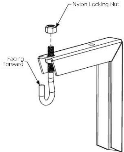
Figure 7

Figure 8

natural_image
Technical line drawing of a mechanical assembly with an inset showing a close-up of a hanging hook component (no text or symbols present)
A Milestone AV Technologies Brand
3100 North Detroit Street
Warsaw, Indiana 46582
P: 574.267.8101 or 800.622.3737
F: 574.267.7804 or 877.325.4832
E: info@da-lite.com
www.da-lite.com
DL-0603 03.15
© 2015 Milestone AV Technologies LLC.

Brand : DA-LITE
Model : 40932
Category : Wall mount