
F1 YF1F2828M - Storage furniture Chief - Free user manual and instructions
Find the device manual for free F1 YF1F2828M Chief in PDF.


| Product Type | Flat Panel Wall Mount |
| Brand | Chief |
| Model | F1 YF1F2828M |
| Compatibility | Flat panel screens up to 65 inches |
| VESA Compatibility | 200x200 to 600x400 mm |
| Weight Capacity | 125 lbs (56.7 kg) |
| Material | Steel |
| Color | Black |
| Mount Type | Fixed / Tilt |
| Tilt Range | 0° to -12° |
| Profile Close to Wall | 2.5 inches (63.5 mm) |
| Installation | Wood stud or concrete wall |
| Leveling | Post-installation leveling |
| Safety Certification | Tested and certified |
| Warranty | 10 years |
| Net Weight | 15 lbs (6.8 kg) |
| Dimensions (H x W x D) | 28 x 28 x 4 inches (711 x 711 x 102 mm) |
Frequently Asked Questions - F1 YF1F2828M Chief
User questions about F1 YF1F2828M Chief
0 question about this device. Answer the ones you know or ask your own.
Ask a new question about this device
Download the instructions for your Storage furniture in PDF format for free! Find your manual F1 YF1F2828M - Chief and take your electronic device back in hand. On this page are published all the documents necessary for the use of your device. F1 YF1F2828M by Chief.
USER MANUAL F1 YF1F2828M Chief
INSTALLATION INSTRUCTIONS

natural_image
Line drawing of a simple rectangular cabinet with a glass door and wheels (no text or symbols)Furniture Racks
DISCLAIMER
Milestone AV Technologies and its affiliated corporations and subsidiaries (collectively "Milestone"), intend to make this manual accurate and complete. However, Milestone makes no claim that the information contained herein covers all details, conditions or variations, nor does it provide for every possible contingency in connection with the installation or use of this product. The information contained in this document is subject to change without notice or obligation of any kind. Milestone makes no representation of warranty, expressed or implied, regarding the information contained herein. Milestone assumes no responsibility for accuracy, completeness or sufficiency of the information contained in this document.
Chief® is a registered trademark of Milestone AV Technologies. All rights reserved.

IMPORTANT SAFETY INSTRUCTIONS

WARNING: A WARNING alerts you to the possibility of serious injury or death if you do not follow the instructions.

CAUTION: A CAUTION alerts you to the possibility of damage or destruction of equipment if you do not follow the corresponding instructions.

WARNING: Failure to read, thoroughly understand, and follow all instructions can result in serious personal injury, damage to equipment, or voiding of factory warranty! It is the installer's responsibility to make sure all components are properly assembled and installed using the instructions provided.

WARNING: Exceeding the weight capacity can result in serious personal injury or damage to equipment! It is the installer's responsibility to make sure the combined weight of all components located within the rack does not exceed the weight capacity listed in the table (Dimensions section below). Use with products heavier than the maximum weight indicated may result in instability or collapse of the rack causing possible injury.
IMPORTANT ! : Minimum spacings between the Accessories and components and the (AV) Equipment Cabinet shall be maintained for safe operation of the equipment when installed in accordance with the National Electric Code, ANSI/NFPA 70-2008. Operating temperature inside rack shall not exceed 104°F.

WARNING: Use this mounting system only for its intended use as described in these instructions. Do not use attachments not recommended by the manufacturer.

WARNING: Never operate this mounting system if it is damaged. Return the mounting system to a service center for examination and repair.

WARNING: Do not use this product outdoors.

WARNING: RISK OF SERIOUS INJURY OR DEATH!
Placing a remote control or toy on the cart may encourage a child to climb onto the cart causing the cart to tip over onto the child. DO NOT place remote controls or toys on the cart!

WARNING: RISK OF SERIOUS INJURY OR DEATH!
Relocating audio and/or video equipment to the cart may result in the cart collapsing or overturning onto a child. DO NOT relocate audio and/or video equipment to the cart!
--SAVE THESE INSTRUCTIONS--
DIMENSIONS

natural_image
Line drawing of a simple cabinet or enclosure with a door and side legs (no text or symbols)FRONT SIDE


natural_image
Line drawing of a simple cabinet with doors and wheels (no text or symbols)
natural_image
Front view of a rectangular electronic component with four connectors and a central grid-like structure (no text or symbols visible)BOTTOM
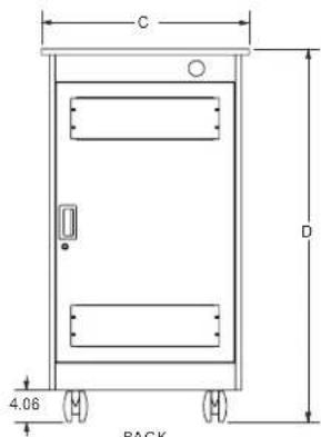
| MODEL | WEIGHT CAPACITY LBS (KG) | RACKING HEIGHT UNITS | OVERALL DEPTH (A) INCH (MM) | USABLE DEPTH (B) INCH (MM) | WIDTH (C) INCH (MM) | HEIGHT (D) INCH (MM) |
| YF1F1228H | 300 (136) | 12 | 30 (762) | 24.12 (612.6) | 26.63 (676.4) | 34 (863.6) |
| YF1F1228M | 300 (136) | 12 | 30 (762) | 24.12 (612.6) | 26.63 (676.4) | 34 (863.6) |
| YF1F1228B | 300 (136) | 12 | 30 (762) | 24.12 (612.6) | 26.63 (676.4) | 34 (863.6) |
| YF1F2028H | 500 (227) | 20 | 30 (762) | 24.12 (612.6) | 26.63 (676.4) | 48 (1219.2) |
| YF1F2028M | 500 (227) | 20 | 30 (762) | 24.12 (612.6) | 26.63 (676.4) | 48 (1219.2) |
| YF1F2028B | 500 (227) | 20 | 30 (762) | 24.12 (612.6) | 26.63 (676.4) | 48 (1219.2) |
| YF1F2828H | 500 (227) | 28 | 30 (762) | 24.12 (612.6) | 26.63 (676.4) | 62 (1574.8) |
| YF1F2828M | 500 (227) | 28 | 30 (762) | 24.12 (612.6) | 26.63 (676.4) | 62 (1574.8) |
| YF1F2828B | 500 (227) | 28 | 30 (762) | 24.12 (612.6) | 26.63 (676.4) | 62 (1574.8) |
LEGEND


Tighten Fastener
Phillips Screwdriver
Destornillador Phillips
The F1 Series racks may be configured with optional accessories (not included) such as levelers, fan panels, etc. All accessory installation instructions accompany the accessories.
NOTE: The bottom cover panel may be removed for wire entry or may be replaced with a filtered fan panel. Follow instructions included with the fan panel. (See Figure 1)
NOTE: The panels on the back door may be replaced with fan panels. Follow instructions included with the fan panel. (See Figure 2)

Figure 1
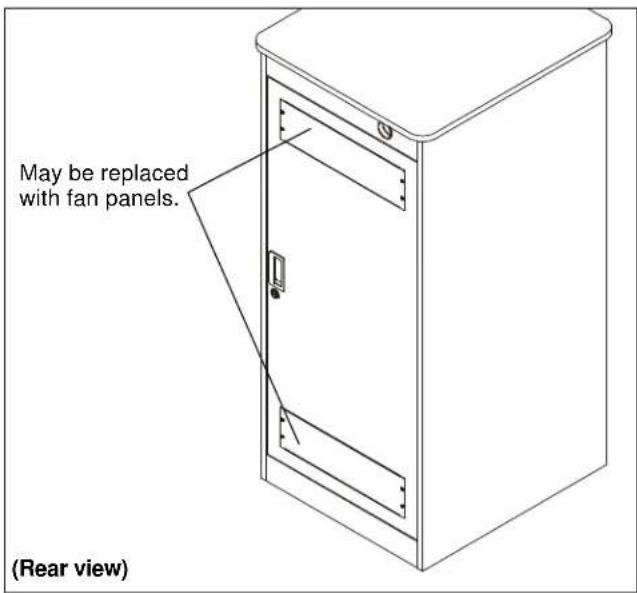
Figure 2
INSTALLING CASTERS
- Attach one caster (B) to each lower corner of the F1 rack using one F1 caster spacer (C) for each caster. (See Figure 3)

Figure 3
-
Lift rack to upright vertical position after casters are installed.
-
Lock casters.
OPTIONAL ASSEMBLY
Levelers
- Add optional levelers to the rack following instructions included with the levelers.
Doors (Change hinged side)
NOTE: The doors can be changed to open on the opposite side from the way they shipped.
- Open door to expose hinge at top and bottom of door. (See Figure 4)
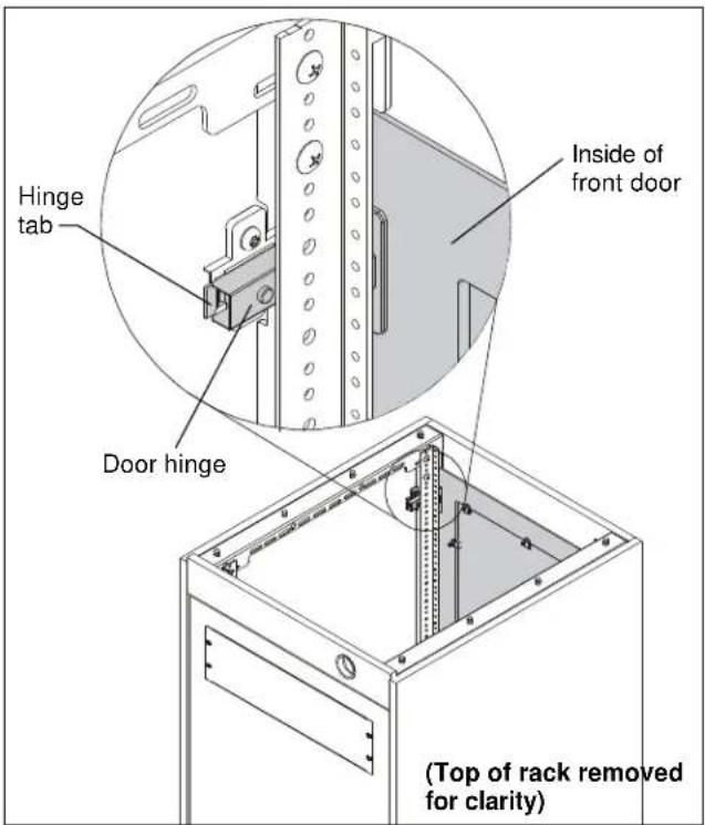
Figure 4
- Squeeze hinge tab at top and bottom of door and pull door straight out to remove from rack.
- Turn door over and re-insert hinges into other side of rack.
- Slide doors into rack until the hinges "click" into the racks.
Hinge Adjustment
If necessary, the door hinges may be used to adjust the depth, horizontal or vertical placement of the doors (See Figure 5).
- Adjusting these screws will allow vertical adjustment (up and down) of the door. (See Figure 5)
- Adjusting this screw will allow depth adjustment (into and out from rack) of the door. (See Figure 5)
- Adjusting this screw will allow horizontal adjustment (side to side) of the door. (See Figure 5)

Figure 5

Figure 6

Figure 7

DANGER: IMPROPER WIRING CAN LEAD TO DEATH OR SEVERE PERSONAL INJURY! Grounding must be installed by qualified personnel using a UL Recognized No. 12AWG Green and Yellow grounding wire connected to grounding lug on rack.
LOADING THE RACK
NOTE: The alignment panels shipped with the racks are optional. They may be removed to facilitate loading of the racks.
Load Distribution

CAUTION: DAMAGE COULD RESULT FROM LIFTING RACK WITH COMPONENTS INSTALLED! Components should be installed only AFTER rack is in an upright vertical position.

CAUTION: BEGIN PLACEMENT OF LOAD AT BOTTOM OF RACK! Load rack, moving from bottom toward top of rack. Loading rack incorrectly may result in instability causing possibly injury and/or damage to components.
- Begin placement of components into the rack at the lowest point.
- Continue placing items into the rack, moving from the bottom upward.

CAUTION: The top of the unit should not be used as a shelf.

CAUTION: DISTRIBUTE LOAD CORRECTLY! Load rack with 2/3 total weight of components in the lower half of rack. Loading rack incorrectly may result in instability causing possible injury and/or damage to components.
YF1F12-20-28
Installation Instructions


Brand : Chief
Model : F1 YF1F2828M
Category : Storage furniture