
3800PDF - Barcode scanners HONEYWELL - Free user manual and instructions
Find the device manual for free 3800PDF HONEYWELL in PDF.


| Product Type | Barcode Scanner |
| Brand | Honeywell |
| Model | 3800PDF |
| Dimensions (H x W x D) | 168 x 95 x 67 mm |
| Weight | 180 g |
| Power Supply | 5V DC via USB (300 mA max) |
| Scan Engine | 2D Imager with PDF417 support |
| Interface | USB (HID Keyboard, Serial Emulation) |
| Scan Rate | Up to 270 scans per second |
| Depth of Field | Up to 10 inches for 10 mil barcode |
| IP Rating | IP41 |
| Operating Temperature | 0°C to 50°C |
| Storage Temperature | -20°C to 70°C |
| Humidity | 5% to 95% non-condensing |
| Drop Specification | Withstands 1.5m drops |
| Light Source | Visible red LED (617 nm) |
| Housing Material | Polycarbonate |
| Warranty | 1 year |
| Maintenance | Clean lens with soft, dry cloth |
| Safety Certification | Class 1 LED product (eye safe) |
| Replaceable Parts | USB cable only (user-replaceable) |
| Repairability | Service by authorized centers |
Frequently Asked Questions - 3800PDF HONEYWELL
User questions about 3800PDF HONEYWELL
0 question about this device. Answer the ones you know or ask your own.
Ask a new question about this device
Download the instructions for your Barcode scanners in PDF format for free! Find your manual 3800PDF - HONEYWELL and take your electronic device back in hand. On this page are published all the documents necessary for the use of your device. 3800PDF by HONEYWELL.
USER MANUAL 3800PDF HONEYWELL
Handheld Linear Imager

User's Guide
Disclaimer
Hand Held Products, Inc. (“Hand Held Products”) reserves the right to make changes in specifications and other information contained in this document without prior notice, and the reader should in all cases consult Hand Held Products to determine whether any such changes have been made. The information in this publication does not represent a commitment on the part of Hand Held Products.
Hand Held Products shall not be liable for technical or editorial errors or omissions contained herein; nor for incidental or consequential damages resulting from the furnishing, performance, or use of this material.
This document contains proprietary information that is protected by copyright. All rights are reserved. No part of this document may be photocopied, reproduced, or translated into another language without the prior written consent of Hand Held Products.
© 2000-2006 Hand Held Products, Inc. All rights reserved.
Web Address: www.handheld.com
Statement of Agency Compliance
This device complies with part 15 of the FCC Rules. Operation is subject to the following two conditions: (1) this device may not cause harmful interference, and (2) this device must accept any interference received, including interference that may cause undesired operation.
FCC Class B Compliance Statement
This equipment has been tested and found to comply with the limits for a Class B digital device pursuant to part 15 of the FCC Rules. These limits are designed to provide reasonable protection against harmful interference in a residential installation. This equipment generates, uses, and can radiate radio frequency energy and, if not installed and used in accordance with the instructions, may cause harmful interference to radio communications. However, there is no guarantee that interference will not occur in a particular installation. If this equipment does cause harmful interference to radio or television reception, which can be determined by turning the equipment off and on, the user is encouraged to try to correct the interference by one or more of the following measures:
- Reorient or relocate the receiving antenna.
- Increase the separation between the equipment and receiver.
- Connect the equipment into an outlet on a circuit different from that to which the receiver is connected.
- Consult the dealer or an experienced radio or television technician for help.
Caution: Any changes or modifications made to this device that are not expressly approved by Hand Held Products, Inc. may void the user's authority to operate the equipment.
Note: To maintain compliance with FCC Rules and Regulations, cables connected to this device must be shielded cables, in which the cable shield wire(s) have been grounded (tied) to the connector shell.
Canadian Notice
This equipment does not exceed the Class B limits for radio noise emissions as described in the Radio Interference Regulations of the Canadian Department of Communications.
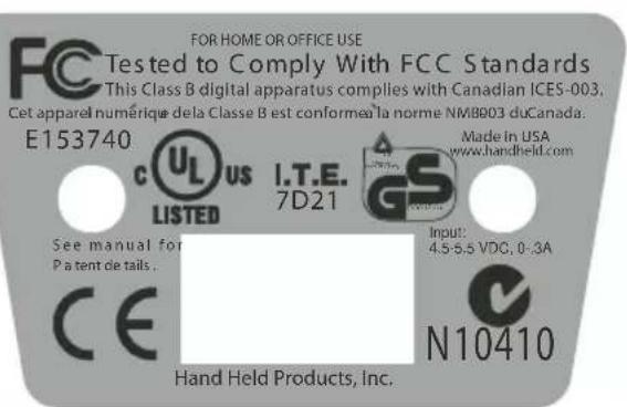
The CE mark on the product indicates that the system has been tested to and conforms with the provisions noted within the 89/336/EEC Electromagnetic Compatibility Directive and the 73/23/EEC Low Voltage Directive.
For further information please contact:
Hand Held Products shall not be liable for use of our product with equipment (i.e., power supplies, personal computers, etc.) that is not CE marked and does not comply with the Low Voltage Directive.
UL and cUL Statement
UL listed UL1950 and CSA 22.2 No.950. cUL listed UL1950 and CSA 22.2 No 950.
LED Safety Statement
This device has been tested in accordance with EN60825-1 LED safety, and has been certified to be under the limits of a Class 1 LED device.
TÜV Statement
TÜV or GS marked to EN60950 and EN60825-1.
C-TIC Statement
Conforms to AS/NZS 3548. C-Tick number: N10410.
Patents
Please refer to the 3800/3900 packaging for patent information.
Chapter 1 - Getting Started
Typical Applications for the 3900....1-1
About This Manual.... 1-1
Unpacking the Scanner.... 1-2
3800 Scanner Identification.... 1-3
3900 Scanner Identification.... 1-3
Connecting the Scanner When Powered by Host (Keyboard Wedge) 1-4
Mounting Information for the 3900 .... 1-5
Specular Zone.... 1-6
Plug and Play.... 1-6
IBM 4683 Ports 5B, 9B, and 17 Interface ...... 1-8
USB Interface 1-9
OCIA Interface 1-11
NCR OCIA Short Format (8 Bit) Interface 1-11
NCR OCIA Long Format (9 Bit) Interface.... 1-12
Nixdorf OCIA Interface.... 1-12
Serial Wedge.... 1-12
Chapter 2 - Terminal Interfaces
Keyboard Wedge Connection.... 2-1
Terminal ID 2-2
Supported Terminals.... 2-3
Keyboard Country 2-5
Keyboard Style 2-5
Keyboard Modifiers.... 2-6
Serial Port Connection.... 2-8
Baud Rate.... 2-9
RS-232 Word Length: Data Bits, Stop Bits, and Parity2-10
RS-232 Handshaking 2-12
Wand Emulation Connection.... 2-12
Wand Emulation Transmission Rate.... 2-13
Wand Emulation Polarity.... 2-14
Wand Emulation Idle 2-14
PDF417 Wand Emulation.... 2-15
Data Block Size.... 2-15
Delay Between Blocks.... 2-15
Overall Checksum.... 2-16
Chapter 3 - Output
Scan Rate 3-1
Beeper Volume.... 3-1
Beeper Tone.... 3-2
Scan Voting 3-2
Reduce Quiet Zone 3-2
Reread Delay 3-3
Good Read Delay.... 3-4
Trigger Mode.... 3-4
Chapter 4 - Data Editing
Prefix/Suffix Overview.... 4-1
To Add a Prefix or Suffix: 4-1
To Clear One or All Prefixes or Suffixes:...... 4-2
To Add a Carriage Return Suffix to all Symbologies.... 4-3
Prefix Selections.... 4-4
Suffix Selections 4-4
Symbology Chart.... 4-5
ASCII Conversion Chart (Code Page 1252)...... 4-6
Function Code Transmit.... 4-7
Intercharacter, Interfunction, and Intermessage Delays ..... 4-7
Intercharacter Delay.... 4-7
User Specified Intercharacter Delay 4-8
Interfunction Delay 4-9
Intermessage Delay.... 4-9
Chapter 5 - Data Formatting
Data Format Editor Introduction....5-1
To Add a Data Format....5-1
Other Programming Selections ....5-2
Data Format Editor Commands....5-2
Data Format Editor....5-4
Data Formatter....5-5
Alternate Data Formats 5-5
Chapter 6 - Secondary Interface
Secondary Code 39 Wand Emulation....6-1
Secondary RS-232 Connection....6-1
Secondary Non Decoded Output Laser Emulation......6-2
Non Decoded Output Laser Emulation Transmission Rate..6-2
Non Decoded Output Laser Emulation Polarity......6-2
Non Decoded Laser Emulation Idle....6-3
Disabling the Secondary Interface....6-3
Secondary Trigger Mode 6-3
Chapter 7 - Symbologies
Introduction....7-1
All Symbologies.... 7-1
Message Length Description 7-2
Codabar....7-3
Start/Stop Characters ....7-3
Check Character 7-4
Concatenation....7-5
Codabar Message Length....7-5
Code 39....7-6
Start/Stop Characters 7-6
Check Character 7-7
Code 39 Message Length 7-7
Code 39 Append....7-8
Base 32 7-8
Full ASCII....7-9
Interleaved 2 of 5....7-10
Check Digit 7-10
Interleaved 2 of 5 Message Length....7-11
Strict Decoding.... 7-11
Code 93....7-12
Code 93 Message Length....7-12
Code 2 of 5....7-13
Code 2 of 5 Message Length....7-13
IATA Code 2 of 5....7-14
IATA Code 2 of 5 Message Length....7-14
Matrix 2 of 5....7-15
Matrix 2 of 5 Message Length 7-15
Code 11....7-16
Check Digits Required.... 7-16
Code 11 Message Length....7-17
Code 128....7-18
Code 128 Message Length....7-19
Telepen 7-20
Telepen Output.... 7-20
Telepen Message Length.... 7-20
UPC A....7-21
Check Digit 7-21
Number System.... 7-21
UPC A, continued 7-22
Addenda 7-22
Addenda Required.... 7-22
Addenda Separator.... 7-23
UPC Strict Decoding.... 7-23
UPC E0 and UPC E1....7-24
UPC E Expand 7-24
Check Digit 7-25
Number System.... 7-25
Addenda 7-26
Addenda Required.... 7-26
Addenda Separator.... 7-27
EAN/JAN 13....7-28
Check Digit....7-28
Addenda....7-29
Addenda Required....7-29
Addenda Separator 7-30
ISBN Enable....7-30
EAN/JAN 8....7-31
Check Digit.... 7-31
Addenda....7-32
Addenda Required....7-32
Addenda Separator 7-33
MSI 7-34
MSI, continued....7-34
Check Character 7-34
MSI Message Length.... 7-35
Plessey....7-36
Plessey Message Length....7-36
RSS-14....7-37
RSS Limited....7-37
RSS Expanded 7-38
RSS Expanded Message Length.... 7-38
China Post Code....7-39
China Post Message Length 7-39
PDF417 7-40
PDF417 Message Length 7-40
Show GLI Blocks....7-41
Scan Diagnostics 7-41
PDF Learn Mode....7-42
MicroPDF417 7-43
MicroPDF417....7-43
MicroPDF417 Message Length.... 7-43
EAN•UCC Composite Symbology 7-44
EAN•UCC Composite 7-44
Enable UPC/EAN Version....7-44
EAN•UCC Composite Code Message Length...... 7-45
Chapter 8 - Cloning
Procedure....8-1
Chapter 9 - Visual Menu
Visual Menu Introduction.... 9-1
Temporary Visual Menu Configuration.... 9-1
Installing Visual Menu from the Web.... 9-1
Upgrading USB Firmware 9-2
Chapter 10 - Interface Keys
Keyboard Function Relationships.... 10-1
Supported Interface Keys 10-3
Chapter 11 - Utilities
To Add a Test Code I.D. Prefix to All Symbologies...... 11-1
Show Software Revision.... 11-1
Show Data Format.... 11-1
Specular Effect Reduction.... 11-2
Chapter 12 - Serial Programming Commands
Conventions.... 12-1
Menu Command Syntax 12-1
Query Commands.... 12-2
Concatenation of Multiple Commands 12-2
Trigger Commands.... 12-4
Resetting the Factory Settings 12-4
Menu Commands 12-5
PDF417 Wand Emulation 12-7
Chapter 13 - Product Specifications
3800 Product Specifications .... 13-1
3900 Product Specifications 13-2
Standard Cable Pinouts.... 13-3
Chapter 14 - Maintenance
Repairs ....14-1
Maintenance....14-1
Replacing the Interface Cable 14-2
Troubleshooting....14-2
Chapter 15 - Customer Support
Product Service and Repair....15-1
Online Product Service and Repair Assistance......15-2
Technical Assistance....15-2
Online Technical Assistance ....15-3
Limited Warranty 15-4
The 3800 is a high performance linear imaging scanner from Hand Held Products. The 3800 marks a new performance level for handheld scanners. Linear imaging technology is defined by a bright and sharply focused aiming line, high resolution imaging, and fast reading speed. The 3800 is comfortable to hold, easy to use, rugged, and excellent for all general scanning applications.
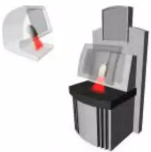
The 3900 is a fixed mount bar code scanner designed for retail kiosks, manufacturing WIP tracking, document processing, or other OEM applications. It is a complete decoded output scanner that is easy to integrate. It communicates with PCs or host terminals via keyboard wedge or a serial RS-232 interface. The 3900 can be used internally or externally. The housing provides protection from dust, dirt, and electrostatic discharge.
Typical Applications for the 3900
The 3900 is an ideal scanner for retail kiosks. The bright aiming line and large working range make scanning easy for untrained users.
The 3900 mounted in a stand makes an efficient bar code document reader; it takes up a minimum of counter space and reads and transmits data quickly.
About This Manual
This User's Guide provides installation and programming instructions for the 3800/3900. Product specifications, dimensions, warranty, and customer support information are also included.
Hand Held Products bar code scanners are factory programmed for the most common terminal and communications settings. If you need to change these settings, programming is accomplished by scanning the bar codes in this guide.
An asterisk (*) next to an option indicates the default setting.
Unpacking the Scanner
Open the carton. The shipping carton or container should contain:
An 3800:

or an 3900:

- Check to make sure everything you ordered is present.
- Save the shipping container for later storage or shipping.
- Check for damage during shipment. Report damage immediately to the carrier who delivered the carton.
3800 Scanner Identification

3900 Scanner Identification
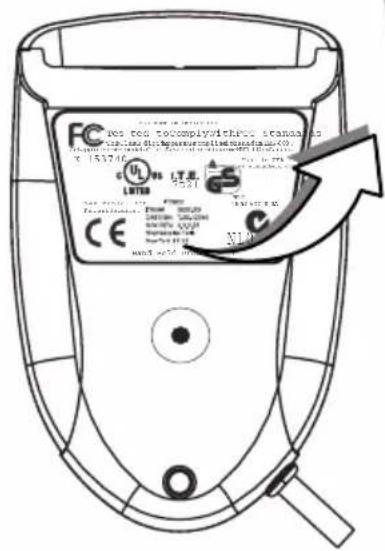
3900 Scanner
Bottom View
Connecting the Scanner When Powered by Host (Keyboard Wedge)
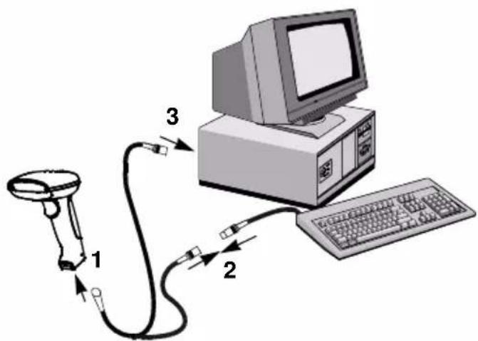
A scanner can be connected between the keyboard and PC as a “keyboard wedge,” plugged into the serial port, or connected to a portable data terminal in wand emulation or non decoded output mode. The following is an example of a keyboard wedge connection:
- Turn off power to the terminal/computer.
- Disconnect the keyboard cable from the back of the terminal/computer.
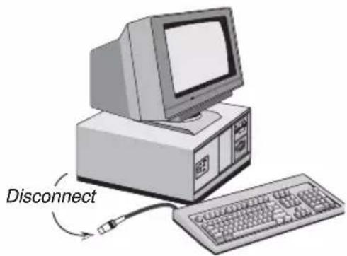
- Connect the appropriate interface cable to the scanner and to the terminal/computer.
-
Turn the terminal/computer power back on. The scanner will beep twice.
-
Verify the scanner operation by scanning a bar code from the back cover of this manual. The scanner will beep once.
Mounting Information for the 3900
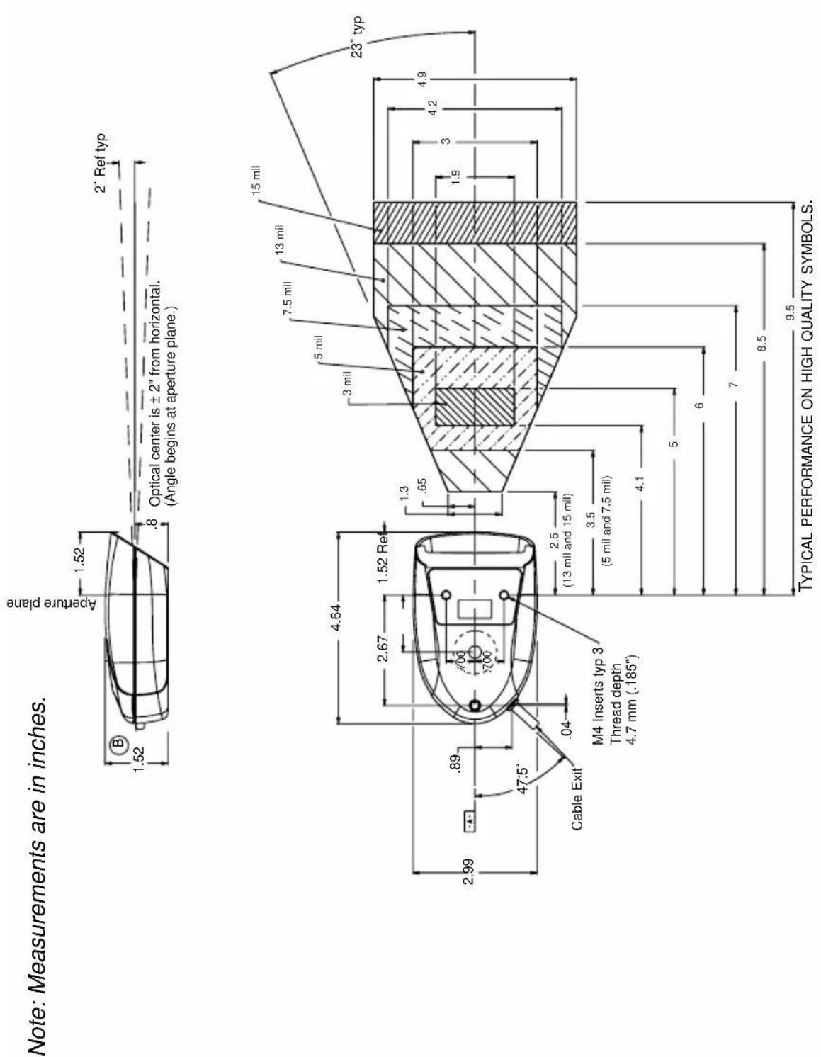
Mounting Information, continued
Specular Zone
The 3900 must be mounted at a 5 degree, or greater, angle to the bar code in order to scan properly:

The scanner is now connected and ready to communicate with your terminal/PC. You must program the scanner for your interface before bar code data can be transmitted to your terminal/PC. If you are using the scanner as a keyboard wedge, turn to page 2-1. If the scanner is connected via a serial port, turn to page 2-8. If this is a wand emulation application, turn to page 2-15, and for a non decoded output connection, turn to page 6-2.
Plug and Play
Plug and Play bar codes provide instant scanner set up for commonly used interfaces.
Note: After you scan one of the codes, power cycle the host terminal to have the interface in effect.
The most common interface is Keyboard Wedge. The following Keyboard Wedge bar code also programs a carriage return (CR) suffix.
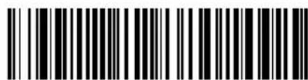
Keyboard Wedge Interface for IBM PC AT and Compatibles
The following Plug and Play bar code for IBM XT and Compatibles also programs a carriage return (CR) suffix.

IBM XT and Compatibles
The following Plug and Play bar code for IBM PS-2 and Compatibles also programs a carriage return (CR) suffix.
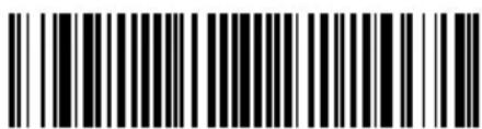
IBM PS-2 and Compatibles
Use Non Decoded Output Laser Emulation when connecting to a secondary terminal with integral decoding. This also sets the transmission rate to 36 scans per second and the polarity to white high.

Non Decoded Output Laser Emulation
For most laptops, scanning the Laptop Direct Connect bar code allows operation of the integral keyboard. The following Laptop Direct Connect bar code also programs a carriage return (CR) suffix.

Laptop Direct Connect
The RS-232 Interface bar code is used when connecting to the serial port of a PC or terminal. The following RS-232 Interface bar code adds a suffix of a CR and LF, and also programs the parameters:
Option
Setting
Baud Rate 9600 bps
Parity Even
Option
Setting
Data Format 7 data bits, parity bit, 1 stop bit (8 bit data)

RS-232 Interface
In Wand Emulation mode, the scanner decodes the bar code then sends data in the same format as a wand scanner. The Same Code format transmits UPC, EAN, Code 128 and Interleaved 2 of 5 bar codes without any changes, but converts all other symbologies to Code 39.

Wand Emulation Same Code
The following Wand Emulation bar code sets the interface to Wand Emulation mode and translates bar code data as Code 39 symbology. It also programs the Transmission Rate to 25 inches per second, and Output Polarity to black high.

Wand Emulation (Code 39 Format)
Note: For the 3800PDF model: When the 3800PDF interface is set to wand emulation, all PDF417 bar code data is transmitted as Code 128. Data from other symbologies follow the rules described above.
IBM 4683 Ports 5B, 9B, and 17 Interface
Note: The following Retail "Plug and Play" codes are for use with the 3800XX-11 and 3800XX-11E models only.
Scan one of the following “Plug and Play” codes to program the 3800 for IBM 4683 Port 5B, 9B, or 17.
Note: After scanning one of these codes, you must re-boot the cash register.

IBM 4683 Port 5B Interface
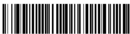
IBM 4683 Port 9B HHBCR-1 Interface

IBM 4683 Port 9B HHBCR-2 Interface

IBM 4683 Port 17 Interface
Each bar code above also programs the following suffixes for each symbology:
Symbology
Suffix
EAN 8 0C
EAN 13 16
UPC A 0D
UPC E 0A
Code 39 00 0A 0B
Interleaved 2 of 5 00 0D 0B
Code 128 00 18 0B
USB Interface
Note: The following USB "Plug and Play" codes (IBM SurePOS handheld and tabletop scanners) are for use with the 3800XX-15 models only.
Scan one of the following “Plug and Play” codes to program the 3800 for IBM SurePos (USB Handheld scanner) or IBM SurePos (USB Tabletop scanner).
Note: After scanning one of these codes, you must re-boot the cash register.

IBM SurePos (USB Handheld Scanner) Interface

IBM SurePos (USB Tabletop Scanner) Interface
Each bar code above also programs the following suffixes for each symbology:
Symbology
EAN 80C
EAN 13 16
UPC A 0D
UPC E 0A
Code 39 00 0A 0B
Interleaved 2 of 5 00 0D 0B
Code 128 00 18 0B
Suffix
Scan one of the following codes to program the 3800 for USB PC Keyboard or USB Macintosh Keyboard.

USB Keyboard (PC)

USB Keyboard (Mac)
Scan the following code to program the 3800 for USB HID bar code scanners.

USB HID Bar Code Scanner
OCIA Interface
Note: The OCIA interfaces are only available on the 3800XX-11 and 3800XX-11E models.
Scan one of the following "Plug and Play" codes to program the 3800 for Generic OCIA, NCR OCIA Short Format (8 bit), NCR OCIA Long Format (9 bit), and Nixdorf OCIA.
Note: After scanning one of these codes, you must re-boot the cash register.
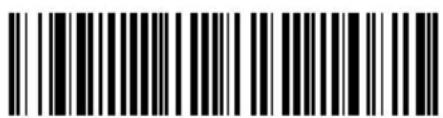
Generic OCIA Interface
The Generic OCIA bar code also programs the following prefixes for each symbology:
Symbology
Prefix
EAN 8 06 06
EAN 13 06
UPC A 01
UPC E 05
NCR OCIA Short Format (8 Bit) Interface

NCR OCIA Short Format (8 Bit) Interface
The NCR OCIA Short Format (8 Bit) bar code also programs the following prefixes for each symbology:
Symbology
Prefix
EAN 8 0F 0F
EAN 13 0F
UPC A 0A
UPC E 0E
NCR OCIA Long Format (9 Bit) Interface

NCR OCIA Long Format (9 Bit) Interface
The NCR OCIA Long Format (9 Bit) bar code also programs the following prefixes for each symbology:
Symbology
Prefix
EAN 8 46 46
EAN 13 46
UPC A 41
UPC E 45
Code 39 42 31
Interleaved 2 of 5 42 32
Code 128 42 33
Nixdorf OCIA Interface

Nixdorf OCIA Interface
The Nixdorf OCIA bar code also programs the following prefixes for each symbology:
Symbology
Prefix
EAN/UPC with Addenda 44 4B
Code 39 44 49
Interleaved 2 of 5 44 48
2 of 5 44 47
Code 128 44 4A
Serial Wedge
The 3800/3900 uses true and TTL signal levels to wedge into an RS-232 serial network. Use 3800/3900 serial wedge cables only to prevent damage to the scanner. Refer to the serial interface programming (pages 2-8 to 2-12) to set the baud rate and communications protocol.
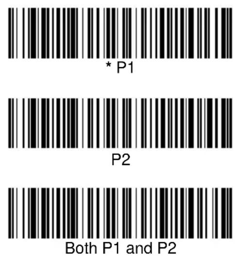
To set up the serial wedge terminal ID, find the terminal ID in the Supported Terminal Chart and follow the instructions on page 2-2. Set the port to which you want the scanned data to transmit. Port 1 corresponds to P1 on the output cable and Port 2 corresponds to P2 on the output cable. Choosing Both sends scanned data to P1 and P2. Default = P1.
Keyboard Wedge Connection
3800/3900 scanners are factory programmed for a keyboard wedge interface to an IBM PC AT with a USA keyboard. If this is your interface and you do not need to modify the settings, skip to Chapter 3 - Output.
If you programmed the scanner for a different terminal interface and/or you want to change to an IBM PC AT and Compatibles Keyboard Wedge interface, scan the bar code below.

IBM PC AT and Compatibles with CR suffix
Terminal ID
If your interface is not a standard PC AT, refer to "Supported Terminals" on page 2-3 through page 2-4, and locate the Terminal ID number for your PC. Scan the Terminal ID bar code below, then scan the numeric bar code(s) on the inside back cover of this manual to program the scanner for your terminal ID. Scan Save to save your selection.
For example, an IBM AT terminal has a Terminal ID of 003. You would scan the Terminal ID bar code, then 0, 0, 3 from the inside back cover, then Save. If you make an error while scanning the digits (before scanning Save), scan the Discard code on the back cover, scan the Terminal ID bar code, scan the digits, and the Save code again.

Terminal ID

Save
Note: After scanning one of these codes, you must power cycle your computer.
Supported Terminals
| Terminal Model(s) Terminal ID | ||
| Apple Mac Mac Classic, SE SE30, II (All) 049 ** | ||
| Apple Mac Powerbook 5300 Series (Portable PC) 049 ** | ||
| DEC VT510, 520, 525 (PC style) 005 | ||
| DEC VT510, 520, 525 (DEC style LK411) | 104 | |
| Esprit 200, 400 005 | ||
| Heath Zenith PC, AT | 090 | |
| HP | Vectra | 003 |
| HP | Vectra ES | 023 |
| IBM | XT | 001 |
| IBM | PS/2 25, 30, 77DX2 002 | |
| IBM | AT, PS/2 30–286, 50, 55SX, 60, 70, 70–061, 70–121, 80 | 003 * |
| IBM 102 key | 3151, 3161, 3162, 3163, 3191, 3192, 3194, 3196, 3197, 3471, 3472, 3476, 3477 | 006 |
| IBM 122 key | 3191, 3192, 3471, 3472 | 007 |
| IBM 122 key | 3196, 3197, 3476, 3477, 3486, 3482, 3488 | 008 |
| IBM 122 key | 3180 | 024 |
| IBM 122 key | 3180 data entry keyboard | 114 |
| IBM DOS/V 106 key | PC & Workstation | 102 |
| IBM SurePOS | USB Handheld Scanner | 128**** |
| IBM SurePOS | USB Tabletop Scanner | 129**** |
| IBM Thinkpad | 360 CSE, 340, 750 | 097 |
| IBM Thinkpad | 106 | |
| IBM Thinkpad | 365, 755CV | 003 |
| I/O 122 key | 2676D, 2677C, 2677D | 008 |
| ITT | 9271 | 007 |
| Lee Data IIS | 007 | |
| NEC 98XX Series | 103 | |
| Olivetti | M19, M200 | 001 |
| Olivetti | M240, M250, M290, M380, P500 | 003 |
| RS-232 True | 000 *** | |
| RS-232 TTL | 000 | |
| Serial Wedge | 050 | |
| Silicon Graphics | Indy, Indigoll | 005 |
| Terminal | Model(s) | Terminal ID |
| Telex 88 key | 078, 078A, 79, 80, 191, 196, 1191,1192, 1471, 1472, 1476, 1477, 1483 | 025 |
| Telex 88 key Data Entry Keyboard 112 | ||
| Telex 102 key | 078, 078A, 79, 80, 191, 196, 1191,1192, 1471, 1472, 1476, 1477, 1483 | 045 |
| Telex 122 key | 078, 078A, 79, 80, 191, 196, 1191,1192, 1471, 1472, 1476, 1477, 1482, 1483 | 046 |
| USB converter 124 | ||
| USB PC Keyboard 124 ***** | ||
| USB Mac Keyboard 125 | ||
| Wand Emulation 061 | ||
* Default for -11, -12 models
** Applies to -12 models only
*** Default for -13 model (applies to -13 models only)
**** Applies to -15 model only. Because special suffixes are required by the IBM SurePOS terminal, it is best to use the Plug and Play bar codes on page 1-10 to program these interfaces, rather than scanning the terminal ID listed in this table.
***** Default for -14, -15 models
Keyboard Country
Scan the Program Keyboard Country bar code below, then scan the numeric bar code(s) from the inside back cover, then the Save bar code to program the keyboard for your country. As a general rule, the following characters are not supported by the scanner for countries other than the United States:
@ | \$ # { } [ ] = / ' \ < > \~
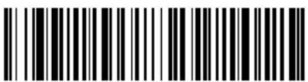
Program Keyboard Country
| Country Code Scan Country | Code Scan |
| Belgium 1 Italy 5Denmark 8 Norway 9Finland 2 Spain 10France 3 Switzerland 6Germany/Austria 4 USA (Default) 0Great Britain 7 |

Save
Keyboard Style
This programs keyboard styles, such as Caps Lock and Shift Lock. Default = Regular.
Regular is used when you normally have the Caps Lock key off.

* Regular
Caps Lock is used when you normally have the Caps Lock key on.

Caps Lock
Shift Lock is used when you normally have the Shift Lock key on (not common to U.S. keyboards).

Automatic Caps Lock is used if you change the Caps Lock key on and off. The software tracks and reflects if you have Caps Lock on or off (AT and PS/2 only). This selection can only be used with systems that have an LED which notes the Caps Lock status.

Emulate External Keyboard should be scanned if you do not have an external keyboard (IBM AT or equivalent). To connect the scanner to a laptop, it may be necessary to use the Automatic Direct Connect selection on page 2-7 in conjunction with the bar code below.

Note: After scanning the Emulate External Keyboard bar code, you must power cycle your computer.
Keyboard Modifiers
This modifies special keyboard features, such as CTRL+ ASCII codes and Turbo Mode.
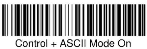
Control + ASCII Mode On: The scanner sends key combinations for ASCII control characters for values 00-1F. Refer to page 10-1 for CTRL+ ASCII Values. Default = Off

Turbo Mode: The scanner sends characters to an IBM AT terminal faster. (For use with IBM AT only.) If the terminal drops characters, do not use Turbo Mode. Default = Off

Turbo Mode On
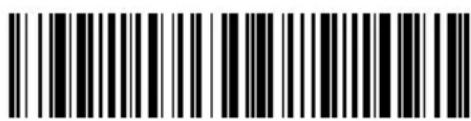
* Turbo Mode Off
Numeric Keypad Mode: Sends numeric characters as if entered from a numeric keypad. Default = Off

Numeric Keypad Mode On

* Numeric Keypad Mode Off
Automatic Direct Connect: Use this selection if you are using a laptop whose keyboard is disabled when you plug in the scanner. This selection can also be used if you have an IBM AT style terminal and the system is dropping characters. Default = Off

Automatic Direct Connect Mode On

* Automatic Direct Connect Mode Off
Serial Port Connection
All communication parameters between the scanner and terminal must match for correct data transfer through the serial port using RS-232 protocol. Scanning the RS-232 interface bar code, programs the scanner for an RS-232 interface at 9600 baud, even parity, 7 data bits, 1 stop bit (8 bit data), and adds a suffix of a CR LF.

RS-232 Interface
- Turn off power to the terminal/computer.
- Connect the appropriate interface cable to the scanner.
Note: For the scanner to work properly, you must have the correct cable for your type of terminal/computer.

- Plug the serial connector into the serial port on the back of your computer/terminal, as shown below. Tighten the two screws to secure the connector to the port.
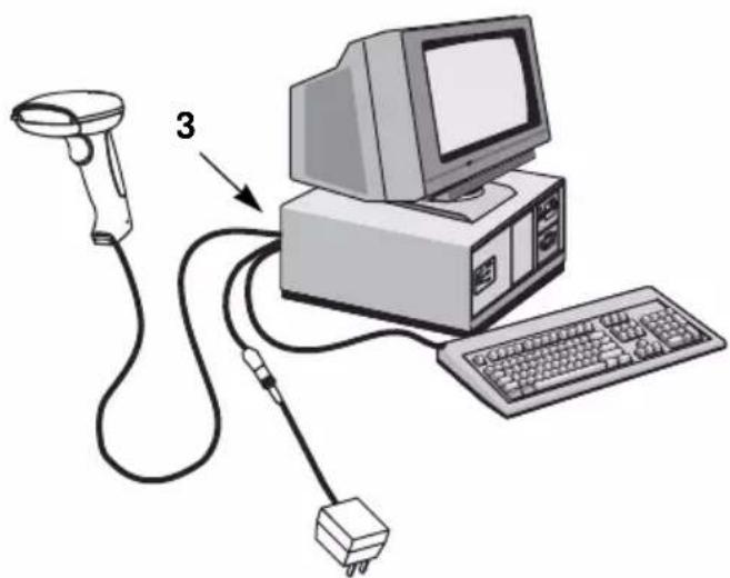
- Plug the power pack into a power source.
- Once the scanner has been fully connected, power up the terminal/computer.
Baud Rate
Baud Rate sends the data from the scanner to the terminal at the specified rate. The host terminal must be set for the same baud rate as the scanner.
Default = 9600.

RS-232 Word Length: Data Bits, Stop Bits, and Parity
Data Bits sets the word length at 7 or 8 bits of data per character. If an application requires only ASCII Hex characters 0 through 7F decimal (text, digits, and punctuation), select 7 data bits. For applications which require use of the full ASCII set, select 8 data bits per character. Default = 7.
Stop Bits sets the stop bits at 1 or 2. Default = 1.
Parity provides a means of checking character bit patterns for validity. Default = Even.

* 7 Data, 1 Stop, Parity Even

7 Data, 1 Stop, Parity None

7 Data, 1 Stop, Parity Odd

7 Data, 1 Stop, Parity Mark

7 Data, 1 Stop, Parity Space

7 Data, 2 Stop, Parity Even

7 Data, 2 Stop Parity None

7 Data, 2 Stop, Parity Odd

7 Data, 2 Stop, Parity Mark
RS-232 Word Length: Data Bits, Stop Bits, and Parity (continued)

RS-232 Handshaking
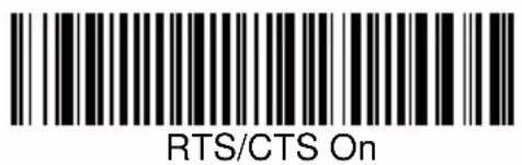
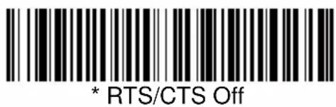
RS-232 handshaking is a set of rules concerning the exchange of data between serially communicating devices. Default = RTS/CTS, XON/XOFF and ACK/NAK Off


Wand Emulation Connection
In Wand Emulation mode, the scanner decodes the bar code then sends data in the same format as a wand scanner. The Code 39 Format converts all symbologies to Code 39. The Same Code Format transmits UPC, EAN, Code 128 and Interleaved 2 of 5 without any changes, but converts all other symbologies to Code 39. These codes set the transmission rate to 25 inches per second and the output polarity to black, high. Default = Code 39 Format.

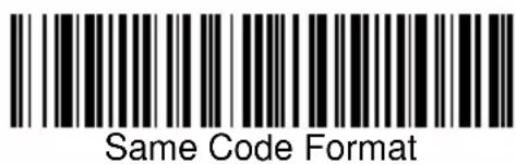
Note: For the 3800PDF model: When the 3800PDF interface is set to wand emulation, all PDF417 bar code data is transmitted as Code 128. Data from other symbologies follow the rules described above.
Wand Emulation Transmission Rate
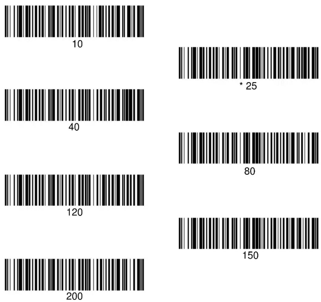
The Transmission Rate is limited by the terminal's ability to receive data without dropping characters. Default = 25 inches/second.
Wand Emulation Polarity
The Polarity can be sent as standard with black bars high, or reversed with white bars high. Default = Black High.
* Black High

White High
Wand Emulation Idle
The idle describes the state of the scanner when no data is being transmitted. When in Wand Emulation mode, you must set the scanner's idle state to match the idle state for the device to which the scanner is connected. Default = Idle High.

* Idle High

Idle Low
PDF417 Wand Emulation
Note: The following Wand Emulation functions are for use with the 3800PDF-12 and 3800PDF-12E scanners only.
Data Block Size
This transmits the PDF417 data in smaller blocks to prevent buffer overflow. Default = 60.
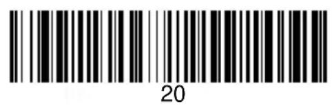


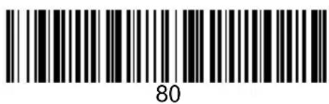
Delay Between Blocks
This sets the delay time between data blocks. Default = 50ms.


Overall Checksum
When this option is turned on, a computed check character is added at the end of the entire message. The check character is the character which when Exclusive-OR'd with every preceding character of the message yields a result of 0x00 (00H). Default = Off.


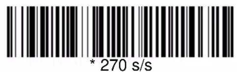
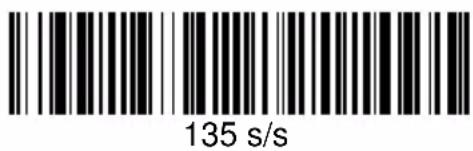
Scan Rate
Adjusting the scan rate changes the current draw when scanning. The slower the scan rate, the lower the current draw. (The standby current remains the same.) Scan speeds are 270 s/s, 135 s/s, and 67 s/s. A scan speed of 270 draws the highest power and has the best performance. A scan speed of 135 has a medium draw with medium performance. A scan speed of 67 draws the lowest power and has the lowest performance. Default = 270 s/s.

Beeper Volume
Default = High.


Beeper Tone
Default = Normal.

Scan Voting
This sets the number of times the same bar code has to be read before it is transmitted to the terminal. Normal uses the default values listed for the symbologies in the Default Charts beginning on page 12-5. High doubles the votes used below the threshold. Default = Voting Normal.

Reduce Quiet Zone
Reducing the quiet zone requirements below AIM guidelines makes it possible to read off-spec bar codes. This feature is effective with all symbologies. Default = Don't Reduce Quite Zone.


Reread Delay
This sets the time period before the scanner can read the same bar code a second time. Setting a reread delay protects against accidental rereads of the same bar code. Longer delays are effective in minimizing accidental rereads at POS (point of sale). Use shorter delays in applications where repetitive bar code scanning is required. Default = Short.
Reread Delay only works when in automatic trigger mode (see page 3-4).

Good Read Delay
This sets the minimum amount of time before the scanner can read another bar code. Default = No Delay.
* No Delay

Short Delay

Medium Delay

Long Delay
Trigger Mode
Manual/Serial Trigger: You can activate the scanner either by pressing the trigger, or using a serial trigger command (see "Trigger Commands" on page 12-4). When in manual trigger mode, the scanner scans until a bar code is read, or until the trigger is released.
When in serial mode, the scanner scans until a bar code has been read or until the deactivate command is sent. In serial mode, the scanner can also be set to turn itself off after a specified time has elapsed (see Serial Trigger Time Out, which follows). Default for 3800.

Manual/Serial Trigger
Serial Trigger Time Out: Use this selection to set a time out (in quarter seconds) of the scanner's trigger when using serial commands to trigger the scanner. Once the scanner has timed out, it must be triggered again either serially or manually. After scanning the Serial Trigger Time Out bar code, set the time out duration (from 0-1200 quarter seconds) by scanning digits from the inside back cover, then scanning Save. Default = 0 (infinite, or no time out).

Serial Trigger Time Out
Manual Trigger, Low Power: The scanner “sleeps,” using only 30 milliamps, until the trigger is pulled. When the trigger is pulled, the scanner wakes up and operates at reduced power until there is no triggering for the time set with the Low Power Time Out bar code. There is a short delay in operation when the scanner is first triggered, but there is no delay when operating in low power mode.

Manual Trigger, Low Power
Note: Manual Trigger, Low Power cannot be used with keyboard wedge applications.
Low Power Time Out: Scan the Low Power Time Out bar code to change the time out duration. Then scan the time out duration (from 0-300 seconds) from the inside back cover, and Save. Default = 2 minutes.
Note: If you make an error while scanning the digits (before scanning Save), scan Discard on the back cover, scan the Lower Power Time Out bar code, scan the correct digits, then Save again.

Low Power Time Out
Automatic Trigger: The scanner scans continuously at full power. Default for 3900.

Automatic Trigger
Presentation Mode: The LEDs are off until a bar code is presented to the scanner. Then the LEDs turn on automatically to read the code. Presentation Mode uses normal office or store ambient light to detect the bar codes.

Presentation Mode
Note: Do not use Presentation Mode with a 3800/3900PDF. Normal office or store ambient light does not provide enough illumination for the 3800/3900PDF to work properly in Presentation Mode.
Prefix/Suffix Overview
When a bar code is scanned, additional information is sent to the host computer along with the bar code data. This group of bar code data and additional, user-defined data is called a “message string.” The selections in this section are used to build the user-defined data into the message string.
Prefix and Suffix characters are data characters that can be sent before and after scanned data. You can specify if they should be sent with all symbologies, or only with specific symbologies. The following illustration shows the breakdown of a message string:
![graph TD A["Prefix"] --> B["Scanned Data"] B --> C["Suffix"] style A fill:#f9f,stroke:#333 style B fill:#ccf,stroke:#333 style C fill:#cfc,stroke:#333 note1["alpha numeric characters"] --> A note2["variable length1-10"] --> B note3["1-10 alpha numeric characters"] --> C](/content/2026/05/1054919/images/9e8b96576633d774d221138dfd97707c0ed7ea854b16e2f2a67034df4003bab7.jpg)
Points to Keep In Mind
- It is not necessary to build a message string. The selections in this chapter are only used if you wish to alter the default settings. Default prefix = None. Default suffix = None.
- A prefix or suffix may be added or cleared from one symbology or all symbologies.
- You can add any prefix or suffix from the ASCII chart (page 4-6), plus Code I.D. and Aim I.D.
- You can string together several entries for several symbologies at one time.
- Enter prefixes and suffixes in the order in which you want them to appear on the output.
To Add a Prefix or Suffix:
Step 1. Scan the Add Prefix or Add Suffix symbol (page 4-4).
Step 2. Determine the 2 digit Hex value from the Symbology Chart (page 4-5) for the symbology to which you want to apply the prefix or suffix.
Step 3. Scan the 2 hex digits from the Programming Chart inside the back cover or scan 9, 9 for all symbologies.
Step 4. Determine the hex value from the Decimal to Hex to ASCII Conversion Chart (page 4-6) for the prefix or suffix you wish to enter.
Step 5. Scan the 2 digit hex value from the Programming Chart inside the back cover.
Step 6. Repeat Steps 4 and 5 for every prefix or suffix character.
Step 7. To add the Code I.D., scan 5, C, 8, 0. To add AIM I.D., scan 5, C, 8, 1. To add a backslash ( ), scan 5, C, 5, C.
Step 8. Scan Save to exit and save, or scan Discard to exit without saving. Repeat Steps 1-6 to add a prefix or suffix for another symbology.
Example: Add a Suffix to a specific symbology
To send a CR (carriage return)Suffix for UPC only:
Step 1. Scan Add Suffix.
Step 2. Determine the 2 digit hex value from the Symbology Chart (page 4-5) for UPC.
Step 3. Scan 6, 3 from the Programming Chart (inside back cover).
Step 4. Determine the hex value from the Decimal to Hex to ASCII Conversion Chart (page 4-6) for the CR (carriage return).
Step 5. Scan 0, D from the Programming Chart (inside back cover).
Step 6. Scan Save, or scan Discard to exit without saving.
To Clear One or All Prefixes or Suffixes:
You can clear a single prefix or suffix, or clear all prefixes/suffixes for a symbology. When you Clear One Prefix (Suffix), the specific character you select is deleted from the symbology you want. When you Clear All Prefixes (Suffixes), all the prefixes or suffixes for a symbology are deleted.
Step 1. Scan the Clear One Prefix or Clear One Suffix symbol.
Step 2. Determine the 2 digit Hex value from the Symbology Chart (page 4-5) for the symbology from which you want to clear the prefix or suffix.
Step 3. Scan the 2 digit hex value from the Programming Chart inside the back cover or scan 9, 9 for all symbologies.
Your change is automatically saved.
To Add a Carriage Return Suffix to all Symbologies
Scan the following bar code if you wish to add a Carriage Return Suffix to all symbologies at once. This action first clears all current suffixes, then programs a carriage return suffix for all symbologies.

Add CR Suffix
All Symbologies
Prefix Selections
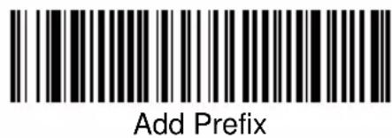


Suffix Selections


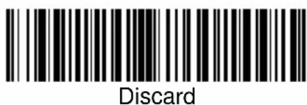
Symbology Chart
| Symbology | Code ID | AIM ID | Hex ID | Symbology | Code ID | AIM ID | Hex ID |
| China Postal | q | ] | X | [interleaved 2 of15 | e | ] | I 0 |
| Codabar | a | ] | F | [Matrix 2 of 5 1 | m | ] | X 0 |
| Code 2 of 5 | f | ] | S | MicroPDF417 6 | R ]L0 | 52 | |
| Code 11 | h | ] | H | MSI 6 8 | g | ] | M 0 |
| Code 39 | b | ] | A | PDF417 2 | r | ]L0 72 | |
| Code 32 PARAF | w | ] | X0 77 | Plessey | n | ] | P 0 |
| Code 93 | i | ]G0 | 69 | RSS-14 | y | ]e0 79 | |
| Code 128 | j | ]C0 | 6A | Telepen | t | ]B0 | 74 |
| EAN/JAN | d | ] | E | UPC 6 4 | c | ]E0 | 63 |
| EAN·UCC Composite | y | ]e0 | 79 | All Symbologies | 99 | ||
| IATA 2 of 5 | f | ] | R | 0 6 6 | |||
6 6 [6 6
Note: Prefix/Suffix entries for specific symbologies override the universal (All Symbologies, 99) entry.
ASCII Conversion Chart (Code Page 1252)
Note: This table applies to U.S. style keyboards. Certain characters may differ depending on your Country Code/PC regional settings.
| Dec | Hex | Char | Dec | Hex | Char | Dec | Hex | Char | Dec | Hex | Char | |
| 0 | 00 | NUL | 32 | 20 | 64 | 40 | @ | 96 | 60 | ‘ | ||
| 1 | 01 | SOH | 33 | 21 | ! | 65 | 41 | A | 97 | 61 | a | |
| 2 | 02 | STX | 34 | 22 | “ | 66 | 42 | B | 98 | 62 | b | |
| 3 | 03 | ETX | 35 | 23 | # | 67 | 43 | C | 99 | 63 | c | |
| 4 | 04 | EOT | 36 | 24 | $ | 68 | 44 | D | 100 | 64 | d | |
| 5 | 05 | ENQ | 37 | 25 | % | 69 | 45 | E | 101 | 65 | e | |
| 6 | 06 | ACK | 38 | 26 | & | 70 | 46 | F | 102 | 66 | f | |
| 7 | 07 | BEL | 39 | 27 | ‘ | 71 | 47 | G | 103 | 67 | g | |
| 8 | 08 | BS | 40 | 28 | ( | 72 | 48 | H | 104 | 68 | h | |
| 9 | 09 | HT | 41 | 29 | ) | 73 | 49 | I | 105 | 69 | i | |
| 10 | 0A | LF | 42 | 2A | * | 74 | 4A | J | 106 | 6A | j | |
| 11 | 0B | VT | 43 | 2B | + | 75 | 4B | K | 107 | 6B | k | |
| 12 | 0C | FF | 44 | 2C | 76 | 4C | L | 108 | 6C | l | ||
| 13 | 0D | CR | 45 | 2D | - | 77 | 4D | M | 109 | 6D | m | |
| 14 | 0E | SO | 46 | 2E | 78 | 4E | N | 110 | 6E | n | ||
| 15 | 0F | SI | 47 | 2F | / | 79 | 4F | O | 111 | 6F | o | |
| 16 | 10 | DLE | 48 | 30 | 0 | 80 | 50 | P | 112 | 70 | p | |
| 17 | 11 | DC1 | 49 | 31 | 1 | 81 | 51 | Q | 113 | 71 | q | |
| 18 | 12 | DC2 | 50 | 32 | 2 | 82 | 52 | R | 114 | 72 | r | |
| 19 | 13 | DC3 | 51 | 33 | 3 | 83 | 53 | S | 115 | 73 | s | |
| 20 | 14 | DC4 | 52 | 34 | 4 | 84 | 54 | T | 116 | 74 | t | |
| 21 | 15 | NAK | 53 | 35 | 5 | 85 | 55 | U | 117 | 75 | u | |
| 22 | 16 | SYN | 54 | 36 | 6 | 86 | 56 | V | 118 | 76 | v | |
| 23 | 17 | ETB | 55 | 37 | 7 | 87 | 57 | W | 119 | 77 | w | |
| 24 | 18 | CAN | 56 | 38 | 8 | 88 | 58 | X | 120 | 78 | x | |
| 25 | 19 | EM | 57 | 39 | 9 | 89 | 59 | Y | 121 | 79 | y | |
| 26 | 1A | SUB | 58 | 3A | : | 90 | 5A | Z | 122 | 7A | z | |
| 27 | 1B | ESC | 59 | 3B | ; | 91 | 5B | | | 123 | 7B | { | |
| 28 | 1C | FS | 60 | 3C | < | 92 | 5C | \ | 124 | 7C | | | |
| 29 | 1D | GS | 61 | 3D | = | 93 | 5D | ] | 125 | 7D | } | |
| 30 | 1E | RS | 62 | 3E | > | 94 | 5E | ^ | 126 | 7E | ~ | |
| 31 | 1F | US | 63 | 3F | ? | 95 | 5F | _ | 127 | 7F |
Function Code Transmit
When this selection is enabled and function codes are contained within the scanned data, the scanner transmits the function code to the terminal. Charts of these function codes are provided in Section 10, Supported Interface Keys. When the scanner is in keyboard wedge mode, the scan code is converted to a key code before it is transmitted. Default = Enable.


Intercharacter, Interfunction, and Intermessage Delays
Some terminals drop information (characters) if data comes through too quickly. Intercharacter, interfunction, and intermessage delays slow the transmission of data, increasing data integrity.
Each delay is composed of a 5 millisecond step. You can program up to 99 steps (of 5 ms each).
Intercharacter Delay
This is a delay of up to 495 milliseconds (in multiples of 5) placed between the transmission of each character of scanned data. You can program up to 99 steps (of 5 ms each). Scan the Intercharacter Delay bar code below, then scan the number of steps, and the SAVE bar code from the inside back cover.
Note: If you make an error while scanning the digits (before scanning Save), scan Discard on the back cover, scan the Intercharacter Delay bar code, scan the correct digits, and Save again.
![graph TD A["Prefix Scanned Data Suffix"] --> B["1"] A --> C["2"] A --> D["3"] A --> E["4"] A --> F["5"] G["Intercharacter Delay"] --> H["1"] G --> I["2"] G --> J["3"] G --> K["4"] G --> L["5"]](/content/2026/05/1054919/images/dc2b71d8fbdc47d46dcd1a7029cad748f680f0311b56b953620d2db390727f47.jpg)

To remove this delay, scan the Intercharacter Delay bar code, then set the number of steps to 00. Scan the SAVE bar code from the inside back cover.
User Specified Intercharacter Delay
This is a delay of up to 495 milliseconds (in multiples of 5) placed after the transmission of a particular character of scanned data. You can program up to 99 steps (of 5 ms each) to follow the character you specify. Scan the Delay Length bar code below, then the number of steps for the delay, and the SAVE bar code from the inside back cover.
Next, scan the Character to Trigger Delay bar code, then the 2 digit hex value for the ASCII character that will trigger the delay (refer to the Decimal to Hex to ASCII conversion chart on page 4-5).
Note: If you make an error while scanning the digits (before scanning Save), scan Discard on the inside back cover, scan the Character to Trigger Delay bar code, scan the correct digits, and Save again.

Character to Trigger Delay

Delay Length
To remove this delay, scan the Delay Length bar code, and set the number of steps to 00. Scan the SAVE bar code from the inside back cover.
Interfunction Delay
This is a delay of up to 495 milliseconds (in multiples of 5) placed between the transmission of each segment of the message string. You can program up to 99 steps (of 5 ms each). Scan the Interfunction Delay bar code below, then scan the number of steps, and the SAVE bar code from the inside back cover.
Note: If you make an error while scanning the
digits (before scanning Save), scan Discard on the inside back cover, scan the Interfunction Delay bar code, scan the correct digits, and Save again.
![graph TD A["Prefix Scanned Data Suffix"] --> B["1 2 3 4 5 STX HT CR LF"] B --> C["Interfunction Delays"] C --> D["1 2 3 4 5 STX HT CR LF"]](/content/2026/05/1054919/images/85890ec48264e0dc01f85204b345cc17e3709ff706d7f989d58e0c5bc36d7745.jpg)

To remove this delay, scan the Interfunction Delay bar code, then set the number of steps to 00. Scan the SAVE bar code from the inside back cover.
Intermessage Delay
This is a delay of up to 495 milliseconds (in multiples of 5) placed between each scan transmission. You can program up to 99 steps (of 5 ms each). Scan the Intermessage Delay bar code below, then scan the number of steps, and the SAVE bar code from the inside back cover.
Note: If you make an error while scanning the digits (before scanning Save), scan Discard on the inside back cover, scan the Intermessage Delay bar code, scan the correct digits, and Save again.


To remove this delay, scan the Intermessage Delay bar code, then set the number of steps to 00. Scan the SAVE bar code from the inside back cover.
Data Format Editor Introduction
The Data Format Editor selections are used to edit scanned data. For example, you can use the Data Format Editor to insert characters at certain points in bar code data as it is scanned. It is not necessary to use the Data Format Editor. A set of defaults for the data format is already programmed in the scanner. The selections in the following pages are used only if you wish to alter the default settings. Default Data Format setting = None.
Normally, when you scan a bar code, it gets outputted automatically; however when you do a format, you must use a "send" command (see Send Commands on page 5-2) within the format program to output data.
Multiple formats may be programmed into the imager. They are stacked in the order in which they are entered. However, the following list presents the order in which formats are applied:
- Specific Term ID, Actual Code ID, Actual Length
- Specific Term ID, Actual Code ID, Universal Length
- Specific Term ID, Universal Code ID, Actual Length
- Specific Term ID, Universal Code ID, Universal Length
- Universal Term ID, Actual Code ID, Actual Length
- Universal Term ID, Actual Code ID, Universal Length
- Universal Term ID, Universal Code ID, Actual Length
- Universal Term ID, Universal Code ID, Universal Length
If you have changed data format settings, and wish to clear all formats and return to the defaults, scan the Default Data Format code on page 5-4.
To Add a Data Format
Step 1. Scan the Enter Data Format symbol (page 5-4).
Step 2. Primary/Alternate Format
Determine if this will be your primary data format, or one of 3 alternate formats. (Alternate formats allow you "single shot" capability to scan one bar code using a different data format. After the one bar code has been read, the scanner reverts to the primary data format. See page 5-5.) If you are programming the primary format, scan 0. If you are programming an alternate format, scan 1, 2, or 3, depending on the alternate format you are programming.
Step 3. Terminal Type
Refer to the Supported Terminals Chart (page 2-3) and locate the Terminal ID number for your PC. Scan three numeric bar codes on the inside back cover to program the scanner for your terminal ID (you must enter 3 digits). For example, scan 0 0 3 for an AT wedge.
Note: The wildcard for all terminal types is 099.
Step 4. Code I.D.
On page 4-5, find the symbology to which you want to apply the data format. Locate the Hex value for that symbology and scan the 2 digit hex value from the Programming Chart.
Step 5. Length
Specify what length (up to 9999 characters) of data will be acceptable for this symbology. Scan the four digit data length from the Programming Chart. (Note: 50 characters is entered as 0050. 9999 is a universal number, indicating all lengths.)
Step 6. Editor Commands
Refer to the Format Editor Commands Chart (page 5-2). Scan the symbols that represent the command you want to enter. 94 alphanumeric characters may be entered for each symbology data format.
Step 7. Scan Save to save your entries.
Other Programming Selections
- Clear One Data Format
This deletes one data format for one symbology. If you are clearing the primary format, scan 0. If you are clearing an alternate format, scan 1, 2, or 3, depending on the alternate format you are clearing. Scan the Terminal Type (refer to the Supported Terminals Chart on page 2-3), Code I.D. and the length of the format you want to delete. That length data format for that symbology is deleted and all other formats are unaffected.
- Save
This exits, saving any Data Format changes.
- Discard
This exits without saving any Data Format changes.
Data Format Editor Commands
Send Commands
F1 Send all characters followed by "xx" key or function code, starting from current cursor position. Syntax = F1xx (xx stands for the hex value for an ASCII code, see Decimal to Hex to ASCII Conversion chart, page 4-6.)
F2 Send "nn" characters followed by "xx" key or function code, starting from current cursor position. Syntax = F2nnxx (nn stands for the numeric value (00-99) for the number of characters and xx stands for the hex value for an ASCII code. See Decimal to Hex to ASCII Conversion chart, page 4-6.)
F3 Send up to but not including "ss" character (Search and Send) starting from current cursor position, leaving cursor pointing to "ss" character followed by "xx" key or function code. Syntax = F3ssxx (ss and xx both stand for the hex values for ASCII codes, see Decimal to Hex to ASCII Conversion chart, page 4-6.)
F4 Send "xx" character "nn" times (Insert) leaving cursor in current cursor position. Syntax = F4xxnn (xx stands for the hex value for an ASCII code, see Decimal to Hex to ASCII Conversion chart, page 4-6, and nn is the numeric value (00-99) for the number of times it should be sent.)
E9 Send all but the last "nn" characters, starting from the current cursor position. Syntax = E9nn (nn is the numeric value (00-99) for the number of characters that will not be sent at the end of the message.)
Move Commands
F5 Move the cursor ahead "nn" characters from current cursor position. Syntax = F5nn (nn stands for the numeric value (00-99) for the number of characters the cursor should be moved ahead.)
F6 Move the cursor back "nn" characters from current cursor position. Syntax = F6nn (nn stands for the numeric value (00-99) for the number of characters the cursor should be moved back.)
F7 Move the cursor to the beginning of the data string. Syntax = F7.
EA Move the cursor to the end of the data string. Syntax = EA
Search Commands
F8 Search ahead for "xx" character from current cursor position, leaving cursor pointing to "xx" character. Syntax = F8xx (xx stands for the hex value for an ASCII code, see Decimal to Hex to ASCII Conversion chart, page 4-6.)
F9 Search back for "xx" character from current cursor position, leaving cursor pointing to "xx" character. Syntax = F9xx (xx stands for the hex value for an ASCII code, see Decimal to Hex to ASCII Conversion chart, page 4-6.)
E6 Search ahead for the first non "xx" character from the current cursor position, leaving cursor pointing to non "xx" character. Syntax = E6xx (xx stands for the hex value for an ASCII code, see Decimal to Hex to ASCII Conversion chart, page 4-6.)
E7 Search back for the first non "xx" character from the current cursor position, leaving cursor pointing to non "xx" character. Syntax = E7xx (xx stands for the hex value for an ASCII code, see Decimal to Hex to ASCII Conversion chart, page 4-6.)
Miscellaneous Commands
FB Suppress all occurrences of up to 15 different characters, starting at the current cursor position, as the cursor is advanced by other commands. When the FC command is encountered, the suppress function is terminated. The cursor is not moved by the FB command. Syntax = FBnnxxyy ..zz where nn is a count of the number of suppressed characters in the list and xxyy ..zz is the list of characters to be suppressed. (xx stands for the hex value for an ASCII code, see Decimal to Hex to ASCII Conversion chart, page 4-6.)
FC Disables suppress filter and clear all suppressed characters. Syntax = FC.
E4 Replaces up to 15 characters in the data string with user specified characters. Replacement continues until the E5 command is encountered. Syntax = E4nnxx 1 xx 2 yy 1 yy 2 ...zz 1 zz 2 where nn is the total count of both characters to be replaced plus replacement characters; xx 1 defines charac-
ters to be replaced and xx2 defines replacement characters, continuing through zz1 and zz2.
E5 Terminates character replacement. Syntax = E5.
FE Compare character in current cursor position to the character "xx." If characters are equal, increment cursor. If characters are not equal, no format match. Syntax = FExx (xx stands for the hex value for an ASCII code, see Decimal to Hex to ASCII Conversion chart, page 4-6.)
EC Check to make sure there is an ASCII number at the current cursor position. If character is not numeric, format is aborted. Syntax = EC.
ED Check to make sure there is a non-numeric ASCII character at the current cursor position. If character is numeric, format is aborted. Syntax = ED.
Data Format Editor

Enter Data Format

Default Data Format
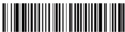
Clear One Data Format

Clear All Data Formats
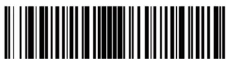
Save

Discard
Data Formatter
When Data Formatter is turned off, the bar code data is output to the host as read (including prefixes and suffixes). Choose one of the following options. Default = Data Formatter On.

* Data Formatter On, but Not Required

Data Formatter Off
When Data Formatter is required, all input data must conform to an edited format or the scanner does not transmit the input data to the host device.

Data Format On, Format Required
Alternate Data Formats
Alternate formats allow you “single shot” capability to scan one bar code using a different data format than your primary format. When data formats are programmed (see page 5-1), you must input whether you are programming the primary format, or an alternate format numbered 1, 2, or 3.
An alternate format is initiated by scanning one of the 3 alternate format bar codes below. The scanner will scan the next bar code, formatting the data with the selected alternate format, then revert immediately to the primary format.

Alternate Data Format 1

Alternate Data Format 2

Alternate Data Format 3
By switching interface cables, the 3800/3900 scanner can communicate with a portable data terminal (secondary interface), in addition to the host terminal (primary interface).
Note: Secondary interfaces do not apply to the 3800XX-15.
The secondary interface can be programmed at any time.
Secondary Code 39 Wand Emulation
In Wand Emulation mode, the scanner decodes the bar code then sends data in the same format as a wand scanner. The Code 39 Format converts all symbologies to Code 39. The Same Code Format transmits UPC, EAN, Code 128 and Interleaved 2 of 5 without any changes, but converts all other symbologies to Code 39. These codes set the transmission rate to 25 inches per second and the output polarity to black, high. Default = Code 39 Format.

* Wand Emulation Code 39 Format

Wand Emulation Same Code Format
Note for the 3800PDF model: When the 3800PDF interface is set to wand emulation, all PDF417 bar code data is transmitted as Code 128. Data from other symbologies follow the rules described above.
Secondary RS-232 Connection
All communication parameters between the scanner and terminal must match for correct data transfer through the serial port using RS-232 protocol.
RS-232 programmable selections are used by both the primary and secondary interfaces. Changing an RS-232 parameter (e.g., baud rate or parity), while in primary or secondary mode will affect both interfaces.

RS-232 Interface
Secondary Non Decoded Output Laser Emulation
Use this selection when connecting to a secondary terminal with integral decoding. This also sets the transmission rate to 36 scans per second and the polarity to white high.

Non Decoded Output
Non Decoded Output Laser Emulation Transmission Rate
The Transmission Rate is limited by the terminal's ability to receive data without dropping characters. Default = 36 scans/second.


Non Decoded Output Laser Emulation Polarity
The Polarity can be sent as standard with white bars high, or reversed with black bars high. Default = White High.


Non Decoded Laser Emulation Idle
The idle describes the state of the scanner when no data is being transmitted. When in Non Decoded mode, you must set the scanner's idle state to match the idle state for the device to which the scanner is connected. Default = High.

Disabling the Secondary Interface
You can temporarily disable the secondary interface, but still retain the secondary interface settings in the scanner's memory by scanning the Disable bar code below. To re-enable the secondary interface, scan the Enable bar code. Default = Disable.

Secondary Trigger Mode
Manual Trigger: You must press the scanner trigger to scan. When not scanning, idle power is maintained. Default = Manual Trigger.

Automatic Trigger: The scanner scans continuously at full power.

Automatic Trigger
Manual Trigger, Low Power: The scanner “sleeps,” using only 30 milliamps, until the trigger is pulled. When the trigger is pulled, the scanner wakes up and operates at normal power until there is no triggering for the time set with the Low Power Time Out bar code. Then, the scanner goes to “sleep” again.
Low Power Time Out: Scan the Low Power Time Out bar code to change the time out duration. Then scan the time out duration (from 0-300 seconds) from the inside back cover and Save. Default = 2 minutes.
Note: If you make an error while scanning the digits (before scanning Save), scan Discard on the back cover, scan the Low Power Time Out bar code, scan the correct digits, and Save again.

Manual Trigger, Low Power

Low Power Time Out
Note: The Secondary Manual Trigger, Lower Power option is not available on the 3800XX-11 and 3800XX-11E in Secondary Non-Decoded Out Laser Emulation Mode.
Introduction
Use this section to program the scanner for Industrial, Retail, and PDF417 Symbology selections.
This programming section contains the following menu selections:
- All Symbologies • IATA Code 2 of 5
• China Post Code • Interleaved 2 of 5
• Codabar • Matrix 2 of 5
• Code 2 of 5 • MicroPDF417 - Code 11 • MSI
• Code 39 • PDF417
• Code 32 PARAF • Plessey - Code 93 • RSS-14
• Code 128 • Telepen
• EAN/JAN • UPC
• EAN•UCC Composite
All Symbologies
If you want to decode all the symbologies allowable for your scanner, scan the All Symbologies On code.

All Symbologies On

All Symbologies Off
Message Length Description
You are able to set the valid reading length of some of the bar code symbologies. If the data length of the scanned bar code doesn't match the valid reading length, the imager will issue an error beep. You may wish to set the same value for minimum and maximum length to force the imager to read fixed length bar code data. This helps reduce the chances of a misread.
EXAMPLE: Decode only those bar codes with a count of 9-20 characters.
Min. length = 09 Max. length = 20
EXAMPLE: Decode only those bar codes with a count of 15 characters.
Min. length = 15 Max. length = 15
For a value other than the minimum and maximum message length defaults, scan the bar codes included in the explanation of the symbology, then scan the digit value of the message length and Save bar codes on the Programming Chart inside the back cover of this manual. The minimum and maximum lengths and the defaults are included with the respective symbologies.
Codabar

Codabar

Start/Stop Characters
Start/Stop characters identify the leading and trailing ends of the bar code. You may either transmit, or not transmit Start/Stop characters. Default = Don't Transmit.

Codabar (continued)
Check Character
Codabar check characters are created using different "modulos." You can program the scanner to read only Codabar bar codes with Modulo 16 check characters. Default = No Check Character.
No Check Character indicates that the scanner reads and transmits bar code data with or without a check character.
When Check Character is set to Validate and Transmit, the scanner will only read Codabar bar codes printed with a check character, and will transmit this character at the end of the scanned data.
When Check Character is set to Validate, but Don't Transmit the unit will only read Codabar bar codes printed with a check character, but will not transmit the check character with the scanned data.

* No Check Character

Validate Modulo 16, but Don't Transmit

Validate Modulo 16 and Transmit
Concatenation
Codabar supports symbol concatenation. When you Enable concatenation, the scanner looks for a Codabar symbol having a "D" start character, adjacent to a symbol having a "D" stop character. In this case the two messages are concatenated into one with the "D" characters omitted. Default = On.

Select Require to prevent the scanner from decoding a lone Codabar symbol.


Codabar Message Length
Scan the bar codes below to change the message length. Refer to Message Length Description (page 7-2) for additional information. Minimum and Maximum lengths = 2-60. Minimum Default = 4, Maximum Default = 60.


Code 39
< Default All Code 39 Settings >

Code 39

Start/Stop Characters
Start/Stop characters identify the leading and trailing ends of the bar code. You may either transmit, or not transmit Start/Stop characters. Default = Don't Transmit.


Code 39, continued
Check Character
No Check Character indicates that the scanner reads and transmits bar code data with or without a check character.
When Check Character is set to Validate, but Don't Transmit, the unit will only read Code 39 bar codes printed with a check character, but will not transmit the check character with the scanned data.
When Check Character is set to Validate and Transmit, the scanner will only read Code 39 bar codes printed with a check character, and will transmit this character at the end of the scanned data. Default = No Check Character.

* No Check Character

Validate, but Don't Transmit

Validate and Transmit
Code 39 Message Length
Scan the bar codes below to change the message length. Refer to Message Length Description (page 7-2) for additional information. Minimum and Maximum lengths = 0-48. Minimum Default = 0, Maximum Default = 48.

Minimum Message Length
Maximum Message Length
Code 39 Append
This function allows the scanner to append the data from several Code 39 bar codes together before transmitting them to the host computer. When this function is enabled, the scanner stores those Code 39 bar codes that start with a space (excluding the start and stop symbols), and does not immediately transmit the data. The scanner stores the data in the order in which the bar codes are read, deleting the first space from each. The scanner transmits the appended data when it reads a Code 39 bar code that starts with a character other than a space. Default = Off.

Base 32
Base 32 is a form of the Code 39 symbology used by Italian pharmacies. This is also known as PARAF.

Code 39, continued
Full ASCII
If Full ASCII Code 39 decoding is enabled, certain character pairs within the bar code symbol will be interpreted as a single character. For example: \$V will be decoded as the ASCII character SYN, and /C will be decoded as the ASCII character #. Default = On.
| NUL %U DLE P | SP SPACE | 0 | 0 | @ | % | V | P | P | ‘ | % | W | |||
| SOHA | DC1 Q | ! | /A | 1 | 1 | A | A | Q | Q | a | +A | q | +Q | |
| STXB | DC2 R | “ | /B | 2 | 2 | B | B | R | R | b | +B | r | +R | |
| ETXC | DC3 S | # | /C | 3 | 3 | C | C | S | S | c | +C | s | +S | |
| EOTD | DC4 T | /D | 4 | 4 | D | D | T | T | d | +D | t | +T | ||
| ENQ E | NAKU | % | /E | 5 | 5 | E | E | U | U | e | +E | u | +U | |
| ACK F | SYNV | & | /F | 6 | 6 | F | F | V | V | f | +F | v | +V | |
| BEL G | ETBW | ‘ | /G | 7 | 7 | G | G | W | W | g | +G | w | +W | |
| BS H | CANX | ( | /H | 8 | 8 | H | H | X | X | h | +H | x | +X | |
| HT I | EMY | ) | /I | 9 | 9 | I | I | Y | Y | i | +I | y | +Y | |
| LF J | SUBZ | * | /J | : | /Z | J | J | Z | Z | j | +J | z | +Z | |
| VT K | ESC %A | + | /K | ; | %F | K | K | [ | %K | k | +K | %P | ||
| FFL | FS %B | , | /L | < | %G | L | L | \ | %L | l | +L | | | %Q | |
| CR M | GS %C | - | - | = | %H | M | M | ] | %M | m | +M | %R | ||
| SON | RS %D | . | . | > | %I | N | N | ^ | %N | n | +N | ~ | %S | |
| SI $O | US %E | / | /O | ? | %J | O | O | _ | %O | o | +O | DEL | %T | |
p + P
Character pairs /M and /N decode as a minus sign and period respectively. Character pairs /P through /Y decode as 0 through 9.

* Full ASCII On

Full ASCII Off
Interleaved 2 of 5
< Default All Interleaved 2 of 5 Settings >
Interleaved 2 of 5

Check Digit
No Check Digit indicates that the scanner reads and transmits bar code data with or without a check digit.
When Check Digit is set to Validate, but Don't Transmit, the unit will only read Interleaved 2 of 5 bar codes printed with a check digit, but will not transmit the check digit with the scanned data.
When Check Digit is set to Validate and Transmit, the scanner will only read Interleaved 2 of 5 bar codes printed with a check digit, and will transmit this digit at the end of the scanned data. Default = No Check Digit.


Interleaved 2 of 5, continued
Interleaved 2 of 5 Message Length
Note: Scan the bar codes below to change the message length. Refer to Message Length Description (page 7-2) for additional information. Minimum and Maximum lengths = 2-80. Minimum Default = 4, Maximum Default = 80.

Minimum Message Length

Maximum Message Length
Strict Decoding
When Strict Decoding is used, the scanner only reads bar codes that are close to spec. This reduces the number of misreads, but also reduces the tolerance for bar codes that are slightly out of spec.

On

* Off
Code 93
< Default All Code 93 Settings >

Code 93


Code 93 Message Length
Note: Scan the bar codes below to change the message length. Refer to Message Length Description (page 7-2) for additional information. Minimum and Maximum lengths = 0-80. Minimum Default = 0, Maximum Default = 80.

Code 2 of 5
Code 2 of 5

Code 2 of 5 Message Length
Note: Scan the bar codes below to change the message length. Refer to Message Length Description (page 7-2) for additional information. Minimum and Maximum lengths = 1-48. Minimum Default = 4, Maximum Default = 48.
IATA Code 2 of 5

IATA Code 2 of 5


IATA Code 2 of 5 Message Length
Note: Scan the bar codes below to change the message length. Refer to Message Length Description (page 7-2) for additional information. Minimum and Maximum lengths = 1-48. Minimum Default = 4, Maximum Default = 48.


Matrix 2 of 5

Matrix 2 of 5


Matrix 2 of 5 Message Length
Note: Scan the bar codes below to change the message length. Refer to Message Length Description (page 7-2) for additional information. Minimum and Maximum lengths = 1-80. Minimum Default = 4, Maximum Default = 80.

Code 11
Code 11


Check Digits Required
This option sets whether 1 or 2 check digits are required with Code 11 bar codes. Default = Two Check Digits.

Code 11 Message Length
Note: Scan the bar codes below to change the message length. Refer to Message Length Description (page 7-2) for additional information. Minimum and Maximum lengths = 1-80. Minimum Default = 4, Maximum Default = 80.

Minimum Message Length
Maximum Message Length
Code 128

Code 128


Substitution
When enabled, the scanner substitutes a

Code 128 Message Length
Note: Scan the bar codes below to change the message length. Refer to Message Length Description (page 7-2) for additional information. Minimum and Maximum lengths = 0-80. Minimum Default = 0, Maximum Default = 80.

Minimum Message Length
Maximum Message Length
Telepen

Telepen

Telepen Output
Using AIM Telepen Output, the scanner reads symbols with start/stop pattern 1 and decodes them as standard full ASCII (start/stop pattern 1). When Original Telepen Output is selected, the scanner reads symbols with start/stop pattern 1 and decodes them as compressed numeric with optional full ASCII (start/stop pattern 2). Default = AIM Telepen Output.


Telepen Message Length
Note: Scan the bar codes below to change the message length. Refer to Message Length Description (page 7-2) for additional information. Minimum and Maximum lengths = 1-60. Minimum Default = 1, Maximum Default = 60.


UPCA

UPCA


Check Digit
This selection allows you to specify whether the check digit should be transmitted at the end of the scanned data or not. Default = On.

Number System
The numeric system digit of a UPC symbol is normally transmitted, but the unit can be programmed so it will not transmit it. Default = On.

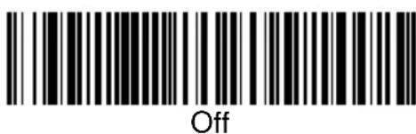
UPC A, continued
Addenda
This selection adds 2 or 5 digits to the end of all scanned UPC A data. Default = Off for both 2 Digit and 5 Digit Addenda.

2 Digit Addenda On

* 2 Digit Addenda Off

5 Digit Addenda On

* 5 Digit Addenda Off
Addenda Required
When Addenda Required is set to on, the scanner will only read UPC A bar codes that have addenda. Default = Off.

Required

* Not Required
UPC A, continued
Addenda Separator
When this feature is on, there is a space between the data from the bar code and the data from the addenda. When turned off, there is no space.
Default = On.


UPC Strict Decoding
When UPC Strict Decoding is used, the scanner only reads bar codes that are close to spec. This reduces the number of misreads, but also reduces the tolerance for bar codes that are slightly out of spec.
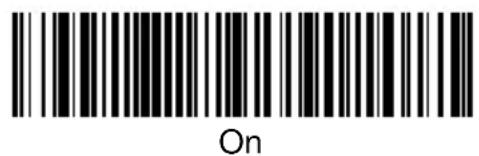
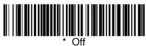
UPC E

UPC E0 and UPC E1
Most UPC bar codes lead with the 0 number system. For these codes, use the UPC E0 selection. If you need to read codes that lead with the 1 number system, use the UPC E1 selection. Default = On (UPC E0) and Off (UPC E1).

* UPC E0 On
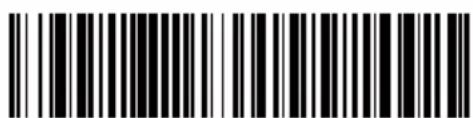
UPC E0 Off

UPC E1 On

* UPC E1 Off
UPC E Expand
UPC E Expand expands the UPC E code to the 12 digit, UPC A format. Default = Off.

On

* Off
UPC E, continued
Check Digit
Check Digit specifies whether the check digit should be transmitted at the end of the scanned data or not. Default = On.


Number System
The numeric system digit of a UPC symbol is normally transmitted, but the unit can be programmed so it will not transmit it. Default = On.


UPC E, continued
Addenda
This selection adds 2 or 5 digits to the end of all scanned UPC E data. Default = Off for both 2 Digit and 5 Digit Addenda.

2 Digit Addenda On

* 2 Digit Addenda Off

5 Digit Addenda On

* 5 Digit Addenda Off
Addenda Required
When Addenda Required is set to on, the scanner will only read UPC E bar codes that have addenda. Default = Off.

Required

* Not Required
UPC E, continued
Addenda Separator
When this feature is on, there is a space between the data from the bar code and the data from the addenda. When turned off, there is no space.
Default = On.


EAN/JAN 13

EAN/JAN 13
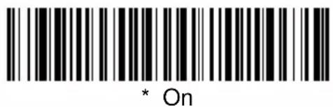

Check Digit
This selection allows you to specify whether the check digit should be transmitted at the end of the scanned data or not. Default = On.

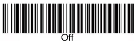
EAN/JAN 13, continued
Addenda
This selection adds 2 or 5 digits to the end of all scanned EAN/JAN 13 data. Default = Off for both 2 Digit and 5 Digit Addenda.

2 Digit Addenda On

* 2 Digit Addenda Off

5 Digit Addenda On

* 5 Digit Addenda Off
Addenda Required
When Addenda Required is set to on, the scanner will only read EAN/JAN 13 bar codes that have addenda. Default = Off.

Required

* Not Required
EAN/JAN 13, continued
Addenda Separator
When this feature is on, there is a space between the data from the bar code and the data from the addenda. When turned off, there is no space.
Default = On.
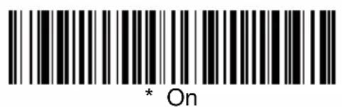

ISBN Enable
This symbology allows the scanner to read ISBN codes on books. Default = Off.


EAN/JAN 8

EAN/JAN 8


Check Digit
This selection allows you to specify whether the check digit should be transmitted at the end of the scanned data or not. Default = On.


EAN/JAN 8, continued
Addenda
This selection adds 2 or 5 digits to the end of all scanned EAN/JAN 8 data. Default = Off for both 2 Digit and 5 Digit Addenda.

2 Digit Addenda On

* 2 Digit Addenda Off

5 Digit Addenda On
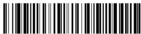
* 5 Digit Addenda Off
Addenda Required
When Addenda Required is set to on, the scanner will only read EAN/JAN 8 bar codes that have addenda. Default = Off.

Required

* Not Required
EAN/JAN 8, continued
Addenda Separator
When this feature is on, there is a space between the data from the bar code and the data from the addenda. When turned off, there is no space.
Default = On.

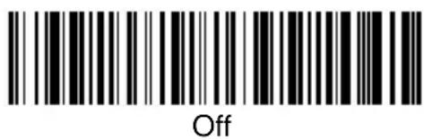
MSI

MSI


MSI, continued
Check Character
Different types of check characters are used with MSI bar codes. You can program the scanner to read only MSI bar codes with Type 10 or Type 11 check characters. Default = Validate Type 10, but Don't Transmit.
When Check Character is set to Validate and Transmit, the scanner will only read MSI bar codes printed with the specified type check character, and will transmit this character at the end of the scanned data.
MSI, continued
When Check Character is set to Validate, but Don't Transmit the unit will only read MSI bar codes printed with the specified type check character, but will not transmit the check character with the scanned data.

* Validate Type 10, but Don't Transmit

Validate Type 10 and Transmit
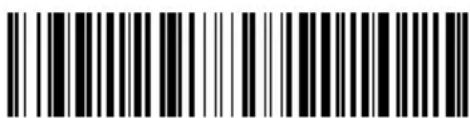
Validate Type 11, but Don't Transmit

Validate Type 11 and Transmit
MSI Message Length
Note: Scan the bar codes below to change the message length. Refer to Message Length Description (page 7-2) for additional information. Minimum and Maximum lengths = 4-48. Minimum Default = 4, Maximum Default = 48.

Minimum Message Length

Maximum Message Length
Plessey
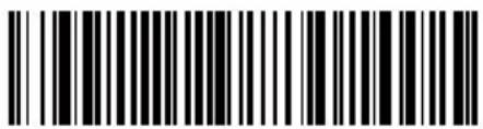
Plessey

On

* Off
Plessey Message Length
Note: Scan the bar codes below to change the message length. Refer to Message Length Description (page 7-2) for additional information. Minimum and Maximum lengths = 4-48. Minimum Default = 4, Maximum Default = 48.

Minimum Message Length

Maximum Message Length
RSS-14
< Default All RSS-14 Settings >

RSS-14
Reduced Space Symbology (RSS) is a family of linear bar codes that meets restricted space requirements, while still providing full product identification.
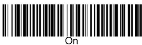

RSS Limited
< Default All RSS Limited Settings >

RSS Limited


RSS Expanded
< Default All RSS Expanded Settings >

RSS Expanded


RSS Expanded Message Length
Note: Scan the bar codes below to change the message length. Refer to Message Length Description (page 7-2) for additional information. Minimum and Maximum lengths = 4-74. Minimum Default = 4, Maximum Default = 74.


China Post Code

China Post Code


China Post Message Length
Note: Scan the bar codes below to change the message length. Refer to Message Length Description (page 7-2) for additional information. Minimum and Maximum lengths = 2-80. Minimum Default = 4, Maximum Default = 80.


PDF417
Note: The following selections are for use with the 3800/3900PDF-12 and 3800/3900PDF-12E scanners only.

PDF417
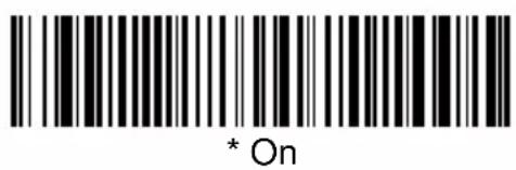

PDF417 Message Length
Note: Scan the bar codes below to change the message length. Refer to Message Length Description (page 7-2) for additional information. Minimum and Maximum lengths = 1-2750. Minimum Default = 1, Maximum Default = 2750.

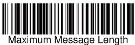
PDF417, continued
Show GLI Blocks
Turning Show GLI Blocks On causes GLI commands to be issued where located within their encoded data sequences. When on, the “\” is used as an escape character and natural occurrences of “\” in data are replaced by “\”. Default = Off.


Scan Diagnostics
When Scan Diagnostics is turned on, the scanner sends a report instead of the decoded message. Your terminal displays the diagnostic information first, then the data from the scanned code. When Scan Diagnostics is turned on, the scanner sends PDF417 symbology information as codes are scanned. Your terminal displays the data from the scanned code first, then the diagnostic information. Default = Off.

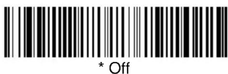
PDF417, continued
The following list shows the information that appears for the PDF417 symbology.
Note: The higher the percentage of unused error correction (UEC), the easier it should be to read each code.
PDF 417: x rows, x cols, xx data & xx chks (ECL = x), UEC = xxx%
Rows = Number of rows
Cols = Number of columns
Data = Number of data words
Chks = Number of check words
ECL = Error Correction Level
UEC = Unused Error Correction
PDF Learn Mode
This setting tells the scanner to brighten the LED's when you have an optimal distance between the scanner and the PDF417 code you are attempting to read. Because some PDF417 codes are more compact than others, the reading distance varies from code to code. When you turn on the PDF Learn Mode, the 3800/3900's light becomes very bright when you are at the best distance for reading the PDF417 code. Default = Off.


MicroPDF417
Note: The following selections are for use with the 3800/3900PDF-12 and 3800/3900PDF-12E scanners only.

MicroPDF417
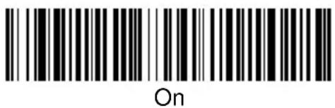

MicroPDF417 Message Length
Scan the bar codes below to change the message length. Refer to Message Length Description (page 7-2) for additional information. Minimum and Maximum lengths = 1-366. Minimum Default = 1, Maximum Default = 366.

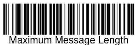
EAN·UCC Composite Symbology
Note: The following selections are for use with the 3800/3900PDF-12 and 3800/3900PDF-12E scanners only.
< Default All EAN•UCC Composite Symbology Settings >

EAN·UCC Composite
Linear codes are combined with a unique 2D composite component to form a new class called EAN•UCC Composite Symbology. EAN•UCC Composite Symbology allows for the co-existence of symbologies already in use.


Enable UPC/EAN Version
Turn on this selection to decode EAN•UCC composite symbols having a UPC or EAN primary component.


EAN·UCC Composite Symbology, continued
EAN•UCC Composite Code Message Length
Scan the bar codes below to change the message length. Refer to Message Length Description (page 7-2) for additional information. Minimum and Maximum lengths = 1-2435. Minimum Default = 1, Maximum Default = 2435.

Minimum Message Length
Maximum Message Length
The cloning procedure reprograms the software in the “destination” scanner’s memory with software from the “source” scanner. Before using this procedure, determine which scanner will be the source (the scanner containing the desired software). The 3800/3900 supports cloning and can act as the source device. The software in the destination scanner will be updated from the source scanner. The destination scanner device must be the same model as the source.
Procedure
- Use the cloning cable (42204559-01) to connect the two scanners for cloning.
- Connect the destination scanner to one of the 10 pin modular connectors on the cloning cable.
- Connect the source scanner (containing the new or updated software) to the remaining 10 pin modular connector on the cloning cable.
- Connect the power supply to the 4 pin mini-DIN connector located on the cloning cable or the scanner cable.
- Make sure both units are on, and then scan the "Clone Destination" bar code with the destination scanner.

Clone Destination Bar Code
- Scan the Clone Source bar code below with the source scanner. The scanner's "Good Read" LED begins blinking periodically indicating cloning is in process.

Clone Source Bar Code
- When cloning is complete, the destination scanner will double beep. This procedure takes approximately two minutes.
- Disconnect the destination scanner from the cloning cable.
- To clone another scanner, repeat steps 1 through 8.
Caution: DO NOT scan the "source" bar code unless you are going to clone a scanner. If you mistakenly scan this bar code, reset the scanner by turning the power off and back on to regain normal operation.
Visual Menu Introduction
Visual Menu provides the ability to configure a scanning device by connecting the scanner to the com port of a PC. Visual Menu allows you to download upgrades to a scanner's firmware, change programmed parameters, and create and print programming bar codes. Using Visual Menu, you can even set up the configuration for a scanner which is not attached to your PC. This enables one expert user to establish the configuration settings for all the devices your company uses, then save these configuration files for others. A configuration file can be e-mailed or, if you prefer, an expert user can create a bar code (or series of bar codes) that contains all the customized programming parameters, and mail or fax the bar code(s) to any location. Users in other locations can scan the bar code(s) to load in the customized parameters.
To communicate with a scanner, Visual Menu requires that the PC have at least one available serial communication port and an RS-232 cable to connect the port to the device. A power supply, which plugs into the cable, is also required.
Visual Menu Operations
The Visual Menu program performs the following operations:
- Displays all configuration data, and saves the information to a file on your PC.
- Configures the device to meet your specific requirements. Visual Menu has all the programming parameters which are available via programming bar codes in this User's Guide.
- Creates and prints a clone bar code which contains the program and configuration data from one device. This bar code can then be used to program additional devices with the same parameters.
- Selects a device from a list, then performs offline or online file configuration for that device.
Temporary Visual Menu Configuration
For quick download communication configuration, scan the Visual Menu bar code to temporarily configure the scanner for Visual Menu settings.

Visual Menu
Installing Visual Menu from the Web
-
Use the following link to access the Developer's Area on our website: http://www.handheld.com/Site.aspx/na/en/developers/download_software/?product=21
-
Click on the entry for Visual Menu.
- When prompted, select Save File, and save the files to the c:\windows\temp directory.
- Once you have finished downloading the file, exit the web site.
- Using Explorer, go to the c:\windows\temp file.
- Double click on the Visualmenu.exe file. Follow the screen prompts to install the Visual Menu program.
- To start Visual Menu, from the Start Menu click on Programs, Visual Menu, Visual Menu.
Note: If you wish, you can create a shortcut to the Visual Menu executable on your desktop.
Upgrading USB Firmware
After you use Visual Menu to upgrade your scanner's firmware, you need to scan the following bar code to upgrade the USB firmware. You must have the USB interface selected. The upgrade takes about 10 seconds, during which a busy tone is generated.
Upgrade EZUSB Firmware
Keyboard Function Relationships
The following Keyboard Function Code, Hex/ASCII Value, and Full ASCII "CTRL"+ relationships apply to all terminals that can be used with the scanner.
| Function Code HEX/ASCII Value Full ASCII “CTRL” + | ||
| NUL 00 2 | ||
| SOH 01 A | ||
| STX 02 B | ||
| ETX 03 C | ||
| EOT 04 D | ||
| ENQ 05 E | ||
| ACK 06 F | ||
| BEL 07 G | ||
| BS 08 H | ||
| HT 09 I | ||
| LF 0A J | ||
| VT 0B K | ||
| FF 0C L | ||
| CR | 0D | M |
| SO | 0E N | |
| SI | 0F O | |
| DLE 10 P | ||
| DC1 11 Q | ||
| DC2 12 R | ||
| DC3 13 S | ||
| DC4 14 T | ||
| NAK 15 U | ||
| SYN 16 V | ||
| ETB 17 | W | |
| CAN 18 X | ||
| EM | 19 Y | |
| SUB 1A Z | ||
| ESC 1B | [ | |
| FS | 1C | \ |
| GS | 1D | ] |
| RS | 1E 6 | |
| US | 1F | - |
The last five characters in the Full ASCII "CTRL"+ column ([] 6 -), apply to US only. The following chart indicates the equivalents of these five characters for different countries.
Country Codes
| United States [ \ ] 6 - | ||||
| Belgium [<] 6 - | ||||
| Scandinavia 8 < 9 6 - | ||||
| France ^ 8 $ 6 = | ||||
| Germany à + 6 - | ||||
| Italy \ + 6 - | ||||
| Switzerland | < | .. | 6 | - |
| United Kingdom | [ ¢ ] 6 - | |||
| Denmark | 8 \ 9 6 - | |||
| Norway | 8 \ 9 6 - | |||
| Spain | [ \ ] 6 - | |||
Supported Interface Keys
| Supported Interface Keys | IBM AT/XT and PS/2 Compatibles, WYSE PC/AT | IBM XTs and Compatibles | IBM, DDC, Memorex Telex, Harris* | |
| NUL 00 Reserved Reserved Reserved | ||||
| SOH 01 Enter (KP) CR/Enter Enter | ||||
| STX 02 Cap Lock Caps Lock F11 | ||||
| ETX 03 ALT make Reserved F12 | ||||
| EOT 04 ALT break Reserved F13 | ||||
| ENQ 05 CTRL make Reserved F14 | ||||
| ACK 06 CTRL break Reserved F15 | ||||
| BEL 07 CR/Enter | CR/Enter New Line | |||
| BS | 08 Reserved Reserved F16 | |||
| HT | 09 Tab | Tab | F17 | |
| LF 0A | Reserved Reserved F18 | |||
| VT | 0B | Tab | Tab | Tab/Field Forward |
| FF 0C | Delete | Delete | Delete | |
| CR | 0D | CR/Enter | CR/Enter | Field Exit/New Line |
| SO | 0E | Insert | Insert | Insert |
| SI | 0F | Escape | Escape | F19 |
| DLE 10 F11 | Reserved Error Reset | |||
| DC1 11 Home | Home | Home | ||
| DC2 12 Print | F20 | |||
| DC3 13 Back Space Back Space | Back Space | |||
| DC4 14 Back Tab Back Tab Backfield/Back Tab | ||||
| NAK 15 F12 | Reserved F21 | |||
| SYN 16 F1 | F1 | F1 | ||
| ETB 17 F2 | F2 | F2 | ||
| CAN | 18 F3 | F3 | F3 | |
| EM | 19 F4 | F4 | F4 | |
| SUB 1A | F5 | F5 | F5 | |
| ESC 1B | F6 | F6 | F6 | |
| FS | 1C | F7 | F7 | F7 |
| GS | 1D | F8 | F8 | F8 |
| RS | 1E | F9 | F9 | F9 |
| US | 1F | F10 | F10 | F10 |
* IBM 3191/92, 3471/72, 3196/97, 3476/77, Telex (all models)
Supported Interface Keys
| Supported | |||
| Interface Keys | IBM, Memorex Telex (102)* Memorex Telex (88)** | ||
| NUL 00 Reserved Reserved | |||
| SOH 01 Enter Enter | |||
| STX 02 F11 PF10 | |||
| ETX 03 F12 PF11 | |||
| EOT 04 F13 PF12 | |||
| ENQ 05 F14 Reserved | |||
| ACK 06 F15 Reserved | |||
| BEL 07 New Line New Line | |||
| BS 08 F16 Field Forward | |||
| HT 09 F17 Field Forward | |||
| LF 0A F18 Reserved | |||
| VT | 0B Tab/Field Forward Field Forward | ||
| FF 0C | Delete | Delete | |
| CR | 0D Field Exit | New Line | |
| SO | 0E Insert | Insert | |
| SI | 0F Clear Erase | ||
| DLE 10 Error Reset | Error Reset | ||
| DC1 11 Home | Reserved | ||
| DC2 12 Print | |||
| DC3 13 Back Space | Back Space | ||
| DC4 14 Back Tab | Back Field | ||
| NAK 15 F19 Reserved | |||
| SYN 16 F1 | PF1 | ||
| ETB 17 F2 | PF2 | ||
| CAN | 18 F3 | PF3 | |
| EM | 19 F4 | PF4 | |
| SUB 1A F5 | PF5 | ||
| ESC 1B F6 | PF6 | ||
| FS | 1C F7 | PF7 | |
| GS | 1D F8 | PF8 | |
| RS | 1E F9 | PF9 | |
| US | 1F F10 Home | ||
* IBM 3196/97, 3476/77, 3191/92, 3471/72, Memorex Telex (all models) with 102 key keyboards
** Memorex Telex with 88 key keyboards
Supported Interface Keys
| Supported Interface Keys | Esprit 200, 400 ANSI | Esprit 200, 400 ASCII | Esprit 200, 400 PC |
| NUL 00 Reserved Reserved Reserved | |||
| SOH 01 New Line New Line New Line | |||
| STX 02 N/A N/A N/A | |||
| ETX 03 N/A N/A N/A | |||
| EOT 04 N/A N/A N/A | |||
| ENQ 05 N/A N/A N/A | |||
| ACK 06 N/A N/A N/A | |||
| BEL 07 New Line New Line New Line | |||
| BS 08 N/A N/A N/A | |||
| HT 09 Tab Tab Tab | |||
| LF 0A N/A N/A N/A | |||
| VT 0B Tab Tab Tab | |||
| FF 0C N/A N/A Delete | |||
| CR 0D New Line New Line New Line | |||
| SO 0E N/A N/A Insert | |||
| SI 0F Escape | Escape | Escape | |
| DLE 10 F11 F11 F11 | |||
| DC1 11 Insert | Insert | Home | |
| DC2 12 F13 F13 Print | |||
| DC3 13 Back Space | Back Space | Back Space | |
| DC4 14 Back Tab | Back Tab | Back Tab | |
| NAK 15 F12 F12 F12 | |||
| SYN 16 F1 | F1 | F1 | |
| ETB 17 F2 | F2 | F2 | |
| CAN 18 F3 | F3 | F3 | |
| EM 19 F4 | F4 | F4 | |
| SUB 1A F5 | F5 | F5 | |
| ESC 1B F6 | F6 | F6 | |
| FS 1C F7 | F7 | F7 | |
| GS 1D F8 | F8 | F8 | |
| RS 1E F9 | F9 | F9 | |
| US 1F F10 F10 F10 | |||
Supported Interface Keys
Supported
Interface Keys Apple Mac/iMac
NUL 00 Reserved
SOH 01 Enter/Numpad Enter
STX 02 CAPS
ETX 03 ALT make
EOT 04 ALT break
ENQ 05 CNTRL make
ACK 06 CNTRL break
BEL 07 RETURN
BS 08 APPLE make
HT 09 TAB
LF 0A APPLE break
VT 0B TAB
FF 0C Del
CR 0D RETURN
SO 0E Ins Help
SI 0F ESC
DLE 10 F11
DC1 11 Home
DC2 12 Prnt Scrn
DC3 13 BACKSPACE
DC4 14 LSHIFT TAB
NAK 15 F12
SYN 16 F1
ETB 17 F2
CAN 18 F3
EM 19 F4
SUB 1A F5
ESC 1B F6
FS 1C F7
GS 1D F8
RS 1E F9
US 1F F10
DEL 7F BACKSPACE
To Add a Test Code I.D. Prefix to All Symbologies
This selection allows you to turn on transmission of a Code I.D. before the decoded symbology. (See the Symbology Chart on page 4-5 for the single character code that identifies each symbology.) This action first clears all current prefixes, then programs a Code I.D. prefix for all symbologies. This is a temporary setting that will be removed when the unit is power cycled.

Add Code I.D. Prefix to
All Symbologies
Show Software Revision
Scan the bar code below to output the current software revision.

Show Revision
Show Data Format
Scan the bar code below to show current data format settings.
Data Format Settings
Specular Effect Reduction
When the On code is scanned, the first pass read rate and voting threshold are increased. Default = Off.
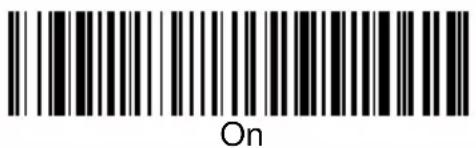

Note: If you want to further limit specular effects, reduce the scan speed using "Scan Rate" on page 3-1.
Serial Programming Commands
The serial programming commands can be used in place of the programming bar codes. Both the serial commands and the programming bar codes will program the 3800/3900. For complete descriptions and examples of each serial programming command, refer to the corresponding programming bar code in this manual.
The device must be set to an RS-232 interface (see page 1-8). The following commands can be sent via a PC com port using terminal emulation software.
Conventions
The following conventions are used for menu and query command descriptions:
parameterA label representing the actual value you should send as part of a command.
[option] An optional part of a command.
{Data} Alternatives in a command.
bold Names of menus, menu commands, buttons, dialog boxes, and windows that appear on the screen.
Menu Command Syntax
Menu commands have the following syntax (spaces have been used for clarity only):
Prefix Tag SubTag {Data} [, SubTag {Data}] [; Tag SubTag {Data}] [...] Storage
Prefix Three ASCII characters: SYN M CR (ASCII 22,77,13).
Tag A 3 character case-insensitive field that identifies the desired menu command group. For example, all RS-232 configuration settings are identified with a Tag of 232.
SubTag A 3 character case-insensitive field that identifies the desired menu command within the tag group. For example, the SubTag for the RS-232 baud rate is BAD.
Data The new value for a menu setting, identified by the Tag and Sub-Tag.
Storage A single character that specifies the storage table to which the command is applied. An exclamation point (!) performs the command's operation on the device's volatile menu configuration table. A period (.) performs the command's operation on the device's non-volatile menu configuration table. Use the non-volatile table only for semi-permanent changes you want saved through a power cycle. (The non-volatile table allows only a limited number of writes.)
Query Commands
Several special characters can be used to query the device about its settings.
^ What is the default value for the setting(s).
? What is the device's current value for the setting(s).
* What is the range of possible values for the setting(s). (The device's response uses a dash (-) to indicate a continuous range of values. A pipe (|) separates items in a list of non-continuous values.)
Tag Field Usage
When a query is used in place of a Tag field, the query applies to the entire set of commands available for the particular storage table indicated by the Storage field of the command. In this case, the SubTag and Data fields should not be used because they are ignored by the device.
SubTag Field Usage
When a query is used in place of a SubTag field, the query applies only to the subset of commands available that match the Tag field. In this case, the Data field should not be used because it is ignored by the device.
Data Field Usage
When a query is used in place of the Data field, the query applies only to the specific command identified by the Tag and SubTag fields.
Concatenation of Multiple Commands
Multiple commands can be issued within one Prefix/Storage sequence. Only the Tag, SubTag, and Data fields must be repeated for each command in the sequence. If additional commands are to be applied to the same Tag, then the new command sequence is separated with a comma (,) and only the SubTag and Data fields of the additional command are issued. If the additional command requires a different Tag field, the command is separated from previous commands by a semicolon (;).
Responses
The device responds to serial commands with one of three responses:
ACK Indicates a good command which has been processed.
ENQ Indicates an invalid Tag or SubTag command.
NAK Indicates the command was good, but the Data field entry was out of the allowable range for this Tag and SubTag combination, e.g., an entry for a minimum message length of 100 when the field will only accept 2 characters.
When responding, the device echoes back the command sequence with the status character inserted directly before each of the punctuation marks (the period, exclamation point, comma, or semicolon) in the command.
Examples of Query Commands
In the following examples, a bracketed notation [ ] depicts a non-displayable response.
Example #1: What is the range of possible values for Codabar Coding Enable?
Enter: cbrena*.
Response: CBRENA0-1[ACK]
This response indicates that Codabar Coding Enable (CBRENA) has a range of values from 0 to 1 (off and on).
Example #2: What is the default value for Codabar Coding Enable?
Enter: cbrena^.
Response: CBRENA1[ACK]
This response indicates that the default setting for Codabar Coding Enable (CBRENA) is 1, or on.
Example #3: What is the device's current setting for Codabar Coding Enable?
Enter: cbrena?.
Response: CBRENA1[ACK]
This response indicates that the device's Codabar Coding Enable (CBRENA) is set to 1, or on.
Example #4: What are the device's settings for all Codabar selections?
Enter: cbr?.
Response: CBRENA1[ACK], SSX0[ACK], CK20[ACK], CCT1[ACK], MIN2[ACK], MAX60[ACK], DFT[ACK].
This response indicates that the device's Codabar Coding Enable (CBRENA) is set to 1, or on;
the Start/Stop Character (SSX) is set to 0, or Don't Transmit; the Check Character (CK2) is set to 0, or Not Required; concatenation (CCT) is set to 1, or Enabled; the Minimum Message Length (MIN) is 2 characters; the Maximum Message Length (MAX) is 60 characters; and the Default setting (DFT) has no value.
Trigger Commands
You can activate and deactivate the scanner with serial trigger commands. First, the scanner must be put in Manual/Serial Trigger Mode either by scanning the Manual/Serial Trigger Mode bar code (page 3-4), or by sending the Manual/Serial Menu Command (page 12-8). Once the scanner is in serial trigger mode, the trigger is activated and deactivated by sending the following commands:
Activate:SYN T CR
Deactivate:SYN U CR
The scanner scans until a bar code has been read, until the deactivate command is sent, or until the serial time out has been reached (see "Serial Trigger Time Out" on page 3-5 for a description, and the serial command on page 12-8).
Resetting the Factory Settings
If you aren't sure what programming options are in your scanner, or you've changed some options and want the factory settings restored, scan the Factory Default Settings bar code below.

Factory Default Settings
The following chart lists the factory default settings (indicated by an asterisk (*) on the programming pages).
Menu Commands
| Selection | Setting* Indicates default | Serial Command# Indicates a numeric entry | Page |
| Factory Default Settings Default DEFALT | |||
| Terminal Interfaces | |||
| Terminal ID | *003 (default for model -12)*000 (default for model -13)*124 (default for models 14-15) | TERMID### 2-2 | |
| Program Keyboard Country KBDCTY 2-5 | |||
| Keyboard Style | *Regular KBDSTY0 2-5 | ||
| Caps Lock KBDSTY1 2-5 | |||
| Shift Lock KBDSTY2 2-6 | |||
| Emulate External Keyboard | KBDSTY5 2-6 | ||
| Automatic Caps Lock KBDSTY6 2-6 | |||
| Keyboard Modifiers | *Control + ASCII Off KBDCAS0 2-6 | ||
| Control + ASCII On | KBDCAS1 2-6 | ||
| *Turbo Mode Off | KBDTMD0 | 2-7 | |
| Turbo Mode On | KBDTMD1 | 2-7 | |
| *Numeric Keypad Off | KBDNPS0 2-7 | ||
| Numeric Keypad On KBDNPS1 2-7 | |||
| *Auto Direct Conn. Off | KBDADC0 2-7 | ||
| Auto Direct Conn. On | KBDADC1 2-7 | ||
| Serial Port Connection | RS-232 | PAP232 | 2-8 |
| Baud Rate | 300 BPS | 232BAD0 | 2-9 |
| 600 BPS | 232BAD1 | 2-9 | |
| 1200 BPS | 232BAD2 | 2-9 | |
| 2400 BPS | 232BAD3 | 2-9 | |
| 4800 BPS | 232BAD4 | 2-9 | |
| *9600 BPS | 232BAD5 | 2-9 | |
| 19200 BPS | 232BAD6 | 2-9 | |
| 38400 BPS | 232BAD7 | 2-9 | |
| Word Length: Data Bits, Stop Bits, and Parity | *7 Data, 1 Stop, Parity Even 232 | WRD3 2-10 | |
| 7 Data, 1 Stop, Parity None 232 | WRD0 2-10 | ||
| 7 Data, 1 Stop, Parity Odd 232 | RD6 2-10 | ||
| 7 Data, 1 Stop, Parity Mark 232 | WRD12 2-10 | ||
| 7 Data, 1 Stop, Parity Space 232 | WRD9 2-10 | ||
| 7 Data, 2 Stop, Parity Even 232 | WRD4 2-10 | ||
| 7 Data, 2 Stop, Parity None 232 | WRD1 2-10 | ||
| 7 Data, 2 Stop, Parity Odd 232 | RD7 2-10 | ||
| 7 Data, 2 Stop, Parity Mark 232 | WRD13 2-10 | ||
| 7 Data, 2 Stop, Parity Space 232 | WRD10 2-10 | ||
| 8 Data, 1 Stop, Parity Even 232 | WRD5 2-10 | ||
| 8 Data, 1 Stop, Parity None 232 | WRD2 2-10 | ||
| 8 Data, 1 Stop, Parity Odd 232 | RD8 2-10 | ||
| 8 Data, 1 Stop, Parity Mark 232 | WRD14 2-10 | ||
| 8 Data, 1 Stop, Parity Space 232 | WRD11 2-10 | ||
| RS-232 Handshaking | *RTS/CTS Off 232CTS0 2-12 | ||
| RTS/CTS On 232CTS1 2-12 | |||
| *XON/XOFF Off 232XON0 2-12 | |||
| XON/XOFF On 232XON1 2-12 | |||
| *ACK/NAK Off 232ACK0 | 2-12 | ||
| ACK/NAK On | 232ACK1 | 2-12 | |
| Wand Emulation Connec-tion | Same Code Format | WNDPAT0 | 2-12 |
| *Code 39 Format | WNDPAT1 | 2-12 | |
| Wand Emulation Transmis-sion Rate | 10 | WNDSPD0 | 2-13 |
| *25 | WNDSPD1 | 2-13 | |
| 40 | WNDSPD2 | 2-13 | |
| 80 | WNDSPD3 | 2-13 | |
| 120 | WNDSPD4 | 2-13 | |
| 150 | WNDSPD5 | 2-13 | |
| 200 | WNDSPD6 | 2-13 | |
| Wand Emulation Polarity | *Black High | WNDPOL0 | 2-14 |
| White High | WNDPOL1 | 2-14 | |
| Wand Emulation Idle | Idle Low WNDIDL0 2-14 | ||
| *Idle High WNDIDL1 2-14 | |||
| PDF417 Wand Emulation | |||
| Data Block Size | 20 WNDBLK0 2-15 | ||
| 40 WNDBLK1 2-15 | |||
| *60 WNDBLK2 2-15 | |||
| 80 WNDBLK3 2-15 | |||
| Delay Between Blocks | 5ms WNDDLY0 2-15 | ||
| *50ms WNDDLY1 2-15 | |||
| 150ms WNDDLY2 2-15 | |||
| 500ms WNDDLY3 2-15 | |||
| Overall Checksum | *Off WNDCHK0 2-16 | ||
| On WNDCHK1 2-16 | |||
| Output Selections | |||
| Scan Rate | 67 s/s | SCNPFM0 3-1 | |
| 135 s/s | SCNPFM1 3-1 | ||
| *270 s/s | SCNPFM2 3-1 | ||
| Beeper Volume | Off BEPLVL0 3-1 | ||
| Low | BEPLVL1 | 3-1 | |
| Medium | BEPLVL2 | 3-1 | |
| *High | BEPLVL3 | 3-1 | |
| Beeper Tone | *Normal Beep | BEPBIP0 | 3-2 |
| Short Beep | BEPBIP1 | 3-2 | |
| Scan Voting | *Voting Normal | DECVLV0 | 3-2 |
| Voting High | DECVLV1 | 3-2 | |
| Reduce Quiet Zone | *Don't Reduce Quiet Zone DECRQZ0 3-2 | ||
| Reduce Quiet Zone | DECRQZ1 3-2 | ||
| Reread Delay | *Short RRDDLY0 3-3 | ||
| Medium | RRDDLY1 | 3-3 | |
| Long | RRDDLY2 | 3-3 | |
| Extra Long | RRDDLY3 | 3-3 | |
| Good Read Delay | *No Delay GRDDLY0 3-4 | ||
| Short Delay GRDDLY1 3-4 | |||
| Medium Delay GRDDLY2 3-4 | |||
| Long Delay GRDDLY3 3-4 | |||
| Trigger Mode | *Manual/Serial Trigger (default for 3800) | TRGMOD0 3-4 | |
| Serial Trigger Time Out *0 TRGSTO##### 3-5 | |||
| Low Power Time Out TRGLPT### 3-5 | |||
| *Automatic Trigger (default for 3900) | TRGMOD1 3-5 | ||
| Manual Trigger, Low Power TRGMOD2 3-5 | |||
| Presentation Mode TRGMOD3 3-6 | |||
| Prefix/Suffix Selections | |||
| Add CR Suffix to All Symbologies | VSUFCR | 4-3 | |
| Prefix | Add Prefix | PREBK2 | 4-4 |
| Clear One Prefix | PRECL2 | 4-4 | |
| Clear All Prefixes | PRECA2 | 4-4 | |
| Suffix | Add Suffix | SUFBK2 | 4-4 |
| Clear One Suffix | SUFCL2 | 4-4 | |
| Clear All Suffixes | SUFCA2 | 4-4 | |
| Function Code Transmit | *Enable | RMVFNC0 | 4-7 |
| Disable | RMVFNC1 | 4-7 | |
| Intercharacter Delay | DLYCHR## 4-8 | ||
| User Specified Intercharac-ter Delay | Delay Length | DLYCRX## 4-8 | |
| Character to Trigger Delay | DLY_XX## | 4-8 | |
| Interfunction Delay | DLYFNC## 4-9 | ||
| Intermessage Delay | DLYMSG## | 4-9 | |
| Data Formatter Selections | |||
| Data Format Editor | *Default Data Format (None) | DFMDF3 | 5-4 |
| Enter Format | DFMBK3 | 5-4 | |
| Clear One Format | DFMCL3 | 5-4 | |
| Clear All Formats | DFMCA3 | 5-4 | |
| Data Formatter | Off DFM_EN0 5-5 | ||
| *On, but Not Required DFM_EN1 | 5-5 | ||
| On, Required DFM_EN2 5-5 | |||
| Alternate Data Formats | 1 VSAF_1 5-5 | ||
| 2 VSAF_2 5-5 | |||
| 3 VSAF_3 5-5 | |||
| Secondary Interface Selections | |||
| Wand Emulation Connec-tion | Same Code Format 2IFTYP0 6-1 | ||
| *Code 39 Format 2IFTYP1 6-1 | |||
| Secondary RS-232 Con- nection | RS-232 Interface 2IFTYP2 6-1 | ||
| Secondary Non Decoded Output Laser Emulation | Non Decoded output 2IFTYP3 6-2 | ||
| Non Decoded Output Laser Emulation Transmission Rate | *36 HLCSPD0 6-2 | ||
| 100 | HLCSPD1 6-2 | ||
| Non Decoded Output Laser Emulation Polarity | Black High | HLCPOL0 | 6-2 |
| *White High | HLCPOL1 | 6-2 | |
| Non Decoded Output Laser Emulation Idle | Low | HLCIDL0 | 6-3 |
| *High | HLCIDL1 | 6-3 | |
| Disabling the Secondary Interface | *Disable | 2IF_END | 6-3 |
| Enable | 2IF_EN1 6-3 | ||
| Secondary Trigger Mode | *Manual Trigger | 2IFTRG0 | 6-3 |
| Automatic Trigger | 2IFTRG1 | 6-3 | |
| Manual Trigger, Low Power | 2IFTRG2 | 6-3 | |
| Low Power Time Out *2min | 2IFLPT | 6-3 | |
| Symbologies | |||
| All Symbologies | All Symbologies Off ALLENA0 | 7-1 | |
| All Symbologies On ALLENA1 | 7-1 | ||
| Codabar | Default All Codabar Settings | CBRDFT | 7-3 |
| Codabar | Off CBRENA0 7-3 | ||
| *On | CBRENA1 | 7-3 | |
| Codabar Start/Stop Char. | *Don't Transmit CBRSSX0 7-3 | ||
| Transmit CBRSSX1 7-3 | |||
| Codabar Check Char. | *No Check Char. CBRCK20 7-4 | ||
| Validate Modulo 16, But Don't Transmit | CBRCK23 7-4 | ||
| Validate Modulo 16, and Transmit | CBRCK24 7-4 | ||
| Codabar Concatenation | Off CBRCCT0 7-5 | ||
| *On CBRCCT1 7-5 | |||
| Require CBRCCT2 7-5 | |||
| Codabar Message Length | Minimum (2-60) *4 CBRMIN## 7-5 | ||
| Maximum (2-60) *60 CBRMAX## 7-5 | |||
| Code 39 | Default All Code 39 Settings | C39DFT | 7-6 |
| Code 39 | Off C39ENA0 7-6 | ||
| *On C39ENA1 7-6 | |||
| Code 39 Start/Stop Char. | *Don't Transmit C39SSX0 | 7-6 | |
| Transmit C39SSX1 7-6 | |||
| Code 39 Check Char. | *No Check Char. C39CK20 | 7-7 | |
| Validate, But Don't Transmit | C39CK21 | 7-7 | |
| Validate, and Transmit | C39CK22 | 7-7 | |
| Code 39 Message Length | Minimum (0 - 48) *0 C39MIN## | 7-7 | |
| Maximum (0 - 48) *48 | C39MAX## | 7-7 | |
| Code 39 Append | *Off C39APP0 7-8 | ||
| On C39APP1 7-8 | |||
| Base 32 | *Off C39B320 7-8 | ||
| On C39B321 7-8 | |||
| Code 39 Full ASCII | *Off C39ASC0 7-9 | ||
| On C39ASC1 7-9 | |||
| Interleaved 2 of 5 | Default All Interleaved 2 of 5 Settings | I25DFT | 7-10 |
| Interleaved 2 of 5 | Off I25ENA0 7-10 | ||
| *On I25ENA1 7-10 | |||
| Interleaved 2 of 5 Check Digit | *No Check Char. I25CK20 7-10 | ||
| Validate, But Don't Transmit | I25CK21 7-10 | ||
| Validate, and Transmit I25CK22 | 7-10 | ||
| Interleaved 2 of 5 Message Length | Minimum (2-80) *4 I25MIN## 7-11 | ||
| Maximum (2-80) *80 I25MAX## | 7-11 | ||
| Interleaved 2 of 5 Strict Decoding | *Off I25STR0 7-11 | ||
| On I25STR1 7-11 | |||
| Code 93 | Default All Code 93 Settings | C93DFT 7-12 | |
| Code 93 | Off C93ENA0 7-12 | ||
| *On C93ENA1 7-12 | |||
| Code 93 Message Length | Minimum (0-80) *0 C93MIN## | 7-12 | |
| Maximum (0-80) *80 | C93MAX## | 7-12 | |
| Code 2 of 5 | Default All Code 2 of 5 Settings | R25DFT 7-13 | |
| Code 2 of 5 | Off R25ENA0 7-13 | ||
| *On R25ENA1 7-13 | |||
| Code 2 of 5 Message Length | Minimum (1 - 48) *4 R25MIN## | 7-13 | |
| Maximum (1 - 48) *48 | R25MAX## | 7-13 | |
| IATA Code 2 of 5 | Default All IATA Code 2 of 5 Settings | A25DFT | 7-13 |
| IATA Code 2 of 5 | Off A25ENA0 7-14 | ||
| *On A25ENA1 7-14 | |||
| IATA Code 2 of 5 Message Length | Minimum (1 - 48) *4 A25MIN## | 7-14 | |
| Maximum (1 - 48) *48 | A25MAX## | 7-14 | |
| Matrix 2 of 5 | Default All Matrix 2 of 5 Settings | X25DFT | 7-14 |
| Matrix 2 of 5 | Off X25ENA0 7-15 | ||
| *On X25ENA1 7-15 | |||
| Matrix 2 of 5 Message Length | Minimum (1 - 80) *4 X25MIN## | 7-15 | |
| Maximum (1 - 80) *80 | X25MAX## | 7-15 | |
| Code 11 | Default All Code 11 Settings | C11DFT 7-16 | |
| Code 11 | Off C11ENA0 7-16 | ||
| *On C11ENA1 7-16 | |||
| Code 11 Check Digits Required | 1 Check Digit C11CK20 7-16 | ||
| *2 Check Digits C11CK21 7-16 | |||
| Code 11 Message Length | Minimum (1 - 80) *4 C11MIN## | 7-17 | |
| Maximum (1 - 80) *80 C11MAX## | 7-17 | ||
| Code 128 | Default All Code 128 Settings | 128DFT 7-18 | |
| Code 128 | Off 128ENA0 7-18 | ||
| *On 128ENA1 7-18 | |||
| <GS> Substitution | *Off 128SGS0 7-18 | ||
| On 128SGS1 7-18 | |||
| Code 128 Message Length | Minimum (0 - 80) *0 128MIN## | 7-19 | |
| Maximum (0 - 80) *80 128MAX## | 7-19 | ||
| Telepen | Default All Telepen Settings | TELDFT | 7-19 |
| Telepen | Off TELENA0 7-20 | ||
| *On TELENA1 7-20 | |||
| Telepen Output | *AIM Telepen Output | TELOLD0 7-20 | |
| Original Telepen Output TELOLD1 | 7-20 | ||
| Telepen Message Length | Minimum (1 - 60) *1 TELMIN## | 7-20 | |
| Maximum (1 - 60) *60 TELMAX## | 7-20 | ||
| UPC A | Default All UPC A Settings | UPADFT | 7-21 |
| UPC A | Off UPAENA0 7-21 | ||
| *On UPAENA1 7-21 | |||
| UPC A Check Digit | Off UPACKX0 7-21 | ||
| *On UPACKX1 7-21 | |||
| UPC A Number System | Off UPANSX0 7-21 | ||
| *On UPANSX1 7-21 | |||
| UPC A 2 Digit Addenda | *Off UPAAD20 7-22 | ||
| On UPAAD21 7-22 | |||
| UPC A 5 Digit Addenda | *Off UPAAD50 7-22 | ||
| On UPAAD51 7-22 | |||
| UPC A Addenda Required | *Off UPAARQ0 7-22 | ||
| On UPAARQ1 7-22 | |||
| UPC A Addenda Separator | Off UPAADS0 7-23 | ||
| *On UPAADS1 7-23 | |||
| UPC Strict Decoding | *Off UPCSTR0 7-23 | ||
| On UPCSTR1 7-23 | |||
| UPC E | Default All UPC E Settings | UPEDFT 7-24 | |
| UPC E0 | Off UPEEN00 7-24 | ||
| *On UPEEN01 7-24 | |||
| UPC E1 | *Off UPEEN10 7-24 | ||
| On UPEEN11 7-24 | |||
| UPC E Expand | *Off UPEEXP0 7-24 | ||
| On UPEEXP1 7-24 | |||
| UPC E Check Digit | Off UPECKX0 7-25 | ||
| *On UPECKX1 7-25 | |||
| UPC E Number System | Off UPENSX0 7-25 | ||
| *On UPENSX1 7-25 | |||
| UPC E 2 Digit Addenda | *Off UPEAD20 7-26 | ||
| On UPEAD21 7-26 | |||
| UPC E 5 Digit Addenda | *Off UPEAD50 7-26 | ||
| On UPEAD51 7-26 | |||
| UPC E Addenda Required | *Off UPEARQ0 7-26 | ||
| On UPEARQ1 7-26 | |||
| UPC E Addenda Separator | Off UPEADS0 7-27 | ||
| *On UPEADS1 7-27 | |||
| EAN/JAN 13 | Default All EAN/JAN 13 Settings | E13DFT 7-28 | |
| EAN/JAN 13 | Off E13ENA0 7-28 | ||
| *On E13ENA1 7-28 | |||
| EAN/JAN 13 Check Digit | Off E13CKX0 7-28 | ||
| *On E13CKX1 7-28 | |||
| EAN/JAN 13 2 Digit Addenda | *Off E13AD20 7-29 | ||
| On E13AD21 7-29 | |||
| EAN/JAN 13 5 Digit Addenda | *Off E13AD50 7-29 | ||
| On E13AD51 7-29 | |||
| EAN/JAN 13 Addenda Required | *Off E13ARQ0 7-29 | ||
| On E13ARQ1 7-29 | |||
| EAN/JAN 13 Addenda Separator | Off E13ADS0 7-30 | ||
| *On E13ADS1 7-30 | |||
| ISBN Enable | *Off E13ISB0 7-30 | ||
| On E13ISB1 7-30 | |||
| EAN/JAN 8 | Default All EAN/JAN 8 Settings | EA8DFT 7-31 | |
| EAN/JAN 8 | Off EA8ENA0 7-31 | ||
| *On EA8ENA1 7-31 | |||
| EAN/JAN 8 Check Digit | Off EA8CKX0 7-31 | ||
| *On EA8CKX1 7-31 | |||
| EAN/JAN 8 2 Digit Addenda | *Off EA8AD20 7-32 | ||
| On EA8AD21 7-32 | |||
| EAN/JAN 8 5 Digit Addenda | *Off EA8AD50 7-32 | ||
| On EA8AD51 7-32 | |||
| EAN/JAN 8 Addenda Required | *Off EA8ARQ0 7-32 | ||
| On EA8ARQ1 7-32 | |||
| EAN/JAN 8 Addenda Separator | Off EA8ADS0 7-33 | ||
| *On EA8ADS1 7-33 | |||
| MSI Default All MSI Settings | MSIDFT 7-34 | ||
| MSI | *Off MSIENA0 7-34 | ||
| On MSIENA1 7-34 | |||
| MSI Check Character | *Validate Type 10, but Don't Transmit | MSICHK0 7-34 | |
| Validate Type 10 and Transmit | MSICHK1 7-34 | ||
| Validate Type 11, but Don't Transmit | MSICHK2 | 7-34 | |
| Validate Type 11 and Transmit | MSICHK3 7-34 | ||
| MSI Message Length | Minimum (4 - 48) *4 | MSIMIN## | 7-34 |
| Maximum (4 - 48) *48 | MSIMAX## | 7-34 | |
| Plessey Default All Plessey Settings | PLSDFT 7-36 | ||
| Plessey | *Off PLSENA0 7-36 | ||
| On PLSENA1 7-36 | |||
| Plessey Message Length | Minimum (4 - 48) *4 PLSMIN## 7-36 | ||
| Maximum (4 - 48) *48 PLSMAX## 7-36 | |||
| RSS-14 | Default All RSS-14 Settings | RSSDFT 7-37 | |
| RSS-14 | *Off RSSENA0 7-37 | ||
| On RSSENA1 7-37 | |||
| RSS Limited | Default All RSS-14 Limited Settings | RSLDFT 7-37 | |
| RSS Limited | *Off RSLENA0 7-37 | ||
| On RSLENA1 7-37 | |||
| RSS Expanded | Default All RSS-14 Expanded Settings | RSEDFT 7-38 | |
| RSS Expanded | *Off RSEENA0 7-38 | ||
| On RSEENA1 7-38 | |||
| RSS Expanded Msg. Length | Minimum (4 - 74) *4 RSEMIN## | 7-38 | |
| Maximum (4 - 74) *74 RSEMAX## 7-38 | |||
| China Post Code | Default All China Post Code Settings | CPCDFT | 7-39 |
| China Post Code | *Off CPCENA0 7-39 | ||
| On CPCENA1 7-39 | |||
| China Post Code Msg. Length | Minimum (2 - 80) *4 CPCMIN## | 7-39 | |
| Maximum (2 - 80) *80 CPCMAX## 7-39 | |||
| PDF417 | Default All PDF417 Settings | PDFDFT | 7-40 |
| PDF417 | Off PDFENA0 7-40 | ||
| *On PDFENA1 7-40 | |||
| PDF417 Message Length | Minimum (1-2750) *1 | PDFMIN## | 7-40 |
| Maximum (1-2750) *2750 | PDFMAX## 7-40 | ||
| Show GLI Blocks | *Off PDFGLI0 7-41 | ||
| On PDFGLI1 7-41 | |||
| Scan Diagnostics | *Off PDFDIA0 7-41 | ||
| On PDFDIA1 7-41 | |||
| PDF Learn Mode | *Off PDFLRN0 7-42 | ||
| On PDFLRN1 7-42 | |||
| MicroPDF417 | Default All MicroPDF417 Settings | MPDDFT 7-43 | |
| MicroPDF417 | *Off MPDENA0 7-43 | ||
| On MPDENA1 7-43 | |||
| MicroPDF417 Message Length | Minimum (1-366) *1 MPDMIN## | 7-43 | |
| Maximum (1-366) *366 MPDMAX## 7-43 | |||
| EAN•UCC Composite Symbology | Default All EAN•UCC Com-posite Symbology Settings | COMDFT 7-44 | |
| EAN•UCC Composite Symbology | *Off COMENA0 7-44 | ||
| On COMENA1 7-44 | |||
| Enable UPC/EAN Version | *Off COMUPC0 7-44 | ||
| On COMUPC1 7-44 | |||
| EAN•UCC Composite Symbology Message Length | Minimum (1-2435) *1 COMMIN## 7-45 | ||
| Maximum (1-2435) *2435 | COMMAX## | 7-45 | |
3800 Product Specifications
| Parameter Specification | ||||
| Dimensions: | ||||
| Height | 6.0 inches (15.2 cm) | |||
| Length | 5.3 inches (13.5 cm) | |||
| Weight | 6.3 ounces (179.2 g) | |||
| Width | 3.1 inches (7.9 cm) | |||
| Light Source 630 nm visible red LED | ||||
| Scan Rate Programmable to 270 scans per second | ||||
| Skew Angle ±30 degrees | ||||
| Pitch Angle ±15 degrees | ||||
| Horizontal Velocity 2 inches (12.7 cm) per second | ||||
| Minimum Reflectance Difference | 30% - LR/HD, 40% - PDF | |||
| Decode Rate 270 decodes per second | ||||
| Power Requirements-12, -13, -14 Models 5VDC ±10% at scanner-11, -15 Models 5-12VDC ±10% at scanner | ||||
| Current Draw: Scanning-11 Model @5Vdc-11 Model @12Vdc-12 Model 275mA-13 Model-15 Model with USB Interface | Standby | Inrush | Low Power | |
| 400mA | 200mA | 550mA | ---- | |
| 150mA | 100mA | 250mA | ---- | |
| 125mA | 300mA | 30mA | ||
| 275mA | 125mA | 250mA | 60μA | |
| 500mA | 265mA | 1.2A | ---- | |
| Temperature Ranges:OperatingStorage | 32°F to +122°F (0°C to +50°C)-4°F to +140°F (-20°C to +60°C) | |||
| Humidity 0 to 95% non-condensing | ||||
| Mechanical Shock | Operational after 25 drops from 5 feet(1.53 m) to concrete | |||
| Vibration Withstands 5G peak from | 20 to 300 Hz | |||
| ESD Sensitivity | 15 kV to any external surface | |||
| Agency Compliance | FCC Class B, CE EMC Class B, CE LowVoltage Directive, EN60825-1,IEC60825-1 LED Safety: Class 1, UL, cUL, TÜVCertified to EN60950, C-Tic | |||
3900 Product Specifications
| Parameter Specification | |||
| Dimensions: | |||
| Height | 1.5 inches (3.8 cm) | ||
| Length | 4.7 inches (11.9 cm) | ||
| Width | 3.1 inches (7.9 cm) | ||
| Light Source 630 nm visible red LED | |||
| Scan Rate Programmable to 270 scans per second | |||
| Skew Angle ±30 degrees | |||
| Pitch Angle ±15 degrees | |||
| Horizontal Velocity 2 inches (12.7 cm) per second | |||
| Minimum Reflectance Difference | 30% (3900 Linear), 40% (3900PDF) | ||
| Decode Rate 270 decodes per second | |||
| Power Requirements 5 VDC ±10% at scanner | |||
| Current Draw Scanning | ____ | Standby | Low Power |
| @270 s/s | 275 mA | 125 mA | 30 mA |
| @67 s/s | 150 mA | 125 mA | 30 mA |
| Temperature Ranges: | |||
| Operating | 32° to +122° F (0° to +50°C) | ||
| Storage | -4° to +140° F (-20° to +60°C) | ||
| Humidity 0 to 95% non-condensing | |||
| Mechanical Shock | Operational after 5 drops from 5 feet(1.53 m) to concrete | ||
| Vibration Withstands 5G peak from | 20 to 300 Hz | ||
| ESD Sensitivity | 15 kV to any external surface | ||
| Agency Compliance | FCC Class B, CE EMC Class B, CE LowVoltage Directive, IEC60825-1 LED Safety: Class 1,UL, cUL listed, TÜV | ||
Standard Cable Pinouts
Laser Output Only (Laser Compatible Bar Image)
Conventional laser data format is provided at the modular connector in the scanner handle. The interface cable is terminated with a 10 pin modular plug, and a 9 pin Type D (squeeze to release) connector that is compatible with all Hand Held Products terminals.
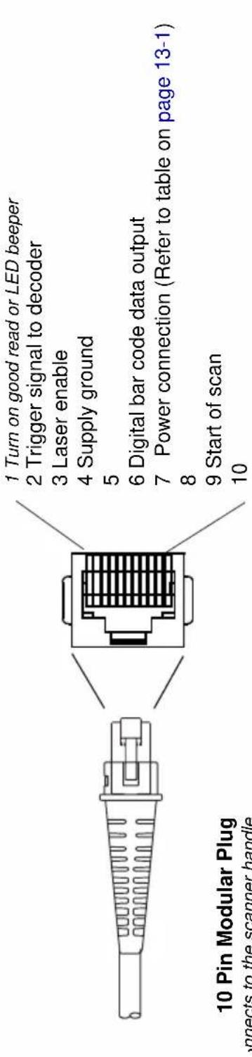
nnects to the scanner handle

9 Pin Type D Female
connects to your terminal
◆ Pins 4 and 9 are populated depending on power supply voltage option. Some decoders may have +12V on pins 4 or 9. Connect to +5VDC ONLY!
Standard Cable Pinouts
Keyboard Wedge
Decoded output data format provided at 10 pin RJ41 modular connector (in scanner handle).
10 Pin RJ41 Modular Plug connects to the scanner handle

Standard Cable Pinouts
Wand Emulation
Decoded output data format provided at 10 pin RJ41 modular connector (in scanner handle).

connects to the scanner handle
Standard Cable Pinouts (Primary Interface Cables) Serial Output
Decoded output data format provided at 10 pin RJ41 modular connector (in scanner handle).
10 Pin RJ41 Modular Plug connects to the scanner handle
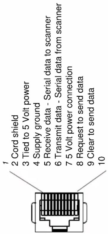
Standard Cable Pinouts USB

Repairs
Repairs and/or upgrades are not to be performed on this product. These services are to be performed only by an authorized service center. See "Customer Support" on page 15-1 for further information.
Maintenance
The 3800/3900 provides reliable and efficient operation with a minimum of care. Although specific maintenance is not required, the following periodic checks ensure dependable scanner operation:
Cleaning the Scanner's Window
Reading performance may degrade if the scanner's window is not clean. If the window is visibly dirty, or if the scanner isn't operating well, clean the window with a soft cloth or facial tissue dampened with water (or a mild detergent- water solution). If a detergent solution is used, rinse with a clean tissue dampened with water only.
The scanner's housing may also be cleaned the same way.

Caution:
Do not submerge the scanner in water. The scanner's housing is not water-tight.
Do not use abrasive wipers or tissues on the scanner's window - abrasive wipers may scratch the window.
Never use solvents (alcohol or acetone) on the housing or window - solvents may damage the finish or the window.
Inspecting Cords and Connectors
Inspect the scanner's interface cable and connector for wear or other signs of damage. A badly worn cable or damaged connector may interfere with scanner operation. Contact your Hand Held Products distributor for information about cable replacement. Cable replacement instructions are on page 14-2.
Replacing the Interface Cable
The standard interface cable is attached to the scanner with an 10-pin modular connector. When properly seated, the connector is held in the 3800 scanner's handle by a flexible retention tab. The 3900 connector is located in the pod at the end of the 3900 cable. The interface cable is designed to be field replaceable.
- Order replacement cables from Hand Held Products or from an authorized distributor.
- When ordering a replacement cable, specify the cable part number of the original interface cable.
To Replace the Interface Cable:
- Turn the power to the host system OFF.
- Disconnect the scanner's cable from the terminal or computer.
- Locate the small hole on the side of the scanner's handle (3800), or on the underside of the connector pod (3900). This is the cable release.
- Straighten one end of a paper clip.
- Insert the end of the paper clip into the small hole and press in. This depresses the retention tab, releasing the connector. Pull the connector out while maintaining pressure on the paper clip, then remove the paper clip.
- Replace with the new cable. Insert the connector into the opening and press firmly. The connector is keyed to go in only one way, and will click into place.
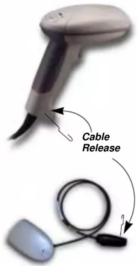
Troubleshooting
The scanner automatically performs self-tests whenever you turn it on. If your scanner is not functioning properly, review the following Troubleshooting Guide to try to isolate the problem.
Is the power on? Is the red illumination beam on?
If the red illumination beam isn't illuminated, check that:
-
The cable is connected properly.
-
The host system power is on (if external power isn't used).
- The trigger works.
Is the scanner having trouble reading your symbols?
If the scanner isn't reading symbols well, check that the symbols:
- Aren't smeared, rough, scratched, or exhibiting voids.
- Aren't coated with frost or water droplets on the surface.
- Are enabled in the scanner or in the decoder to which the scanner connects.
Is the bar code displayed but not entered?
The bar code is displayed on the host device correctly, but you still have to press a key to enter it (the Enter/Return key or the Tab key, for example).
You need to program a suffix. Programming a suffix enables the scanner to output the bar code data plus the key you need (such as "CR") to enter the data into your application. Refer to "Prefix/Suffix Overview" on page 4-1 for further information.
Does the scanner read the bar code incorrectly?
If the scanner reads a bar code, but the data is not displayed correctly on the host screen:
- The scanner may not be programmed for the appropriate terminal interface. For example, you scan "12345" and the host displays "@es%."
Reprogram the scanner with the correct Plug and Play or Terminal selection bar code. See Chapter 1 and Chapter 2.
- The scanner may not be programmed to output your bar code data properly. For example, you scan "12345" and the host displays "A12345B."
Reprogram the scanner with the proper symbology selections. See Chapter 7.
The scanner won't read your bar code at all.
- Scan the sample bar codes in the back of this manual. If the scanner reads the sample bar codes, check that your bar code is readable. Verify that your bar code symbology is enabled (see Chapter 7).
- If the scanner still can't read the sample bar codes, scan "All Symbologies" on page 7-1.
If you aren't sure what programming options have been set in the scanner, or if you want the factory default settings restored, scan "Factory Default Settings" on page 12-4.
Product Service and Repair
Hand Held Products provides service for all its products through service centers throughout the world. To obtain warranty or non-warranty service, return the unit to Hand Held Products (postage paid) with a copy of the dated purchase record attached. Contact the appropriate location below to obtain a Return Material Authorization number (RMA #) before returning the product.
North America
Hand Held Products Corporate Offices
Telephone: (800) 782-4263, option 3
Fax: (704) 566-6015
E-mail: naservice@handheld.com
América Latina
Hand Held Products América Latina
Hand Held Products São Paulo
Europe, Middle East, and Africa
Hand Held Products Europe
Telephone: +31 (0) 40 29 01 633
Fax: +31 (0) 40 2901631
E-mail: euservice@handheld.com
Asia Pacific
Hand Held Products Asia/Pacific
Telephone: +852-2511-3050
Fax: +852-2511-3557
E-mail: apservice@handheld.com
Japan
Hand Held Products Japan
Telephone: +81-3-5770-6312
Fax: +81-3-5770-6313
E-mail: apservice@handheld.com
Online Product Service and Repair Assistance
You can also access product service and repair assistance online at www.handheld.com.
Technical Assistance
If you need assistance installing or troubleshooting, please call your Distributor or the nearest Hand Held Products technical support office:
North America/Canada:
Telephone: (800) 782-4263, option 4 (8 a.m. to 6 p.m. EST)
Fax number: (315) 685-4960
E-mail: natechsupport@handheld.com
América Latina:
Europe, Middle East, and Africa:
Telephone-
European Ofc: Int+31 (0) 40 79 99 393
U.K. Ofc: Int+44 1925 240055
E-mail: eutechsupport@handheld.com
Asia Pacific:
Telephone: Int+852-3188-3485 or 2511-3050
E-mail: aptechsupport@handheld.com
Online Technical Assistance
You can also access technical assistance online at www.handheld.com.
Limited Warranty
Hand Held Products, Inc. ("Hand Held Products") warrants its products to be free from defects in materials and workmanship and to conform to Hand Held Products' published specifications applicable to the products purchased at the time of shipment. This warranty does not cover any Hand Held Products product which is (i) improperly installed or used; (ii) damaged by accident or negligence, including failure to follow the proper maintenance, service, and cleaning schedule; or (iii) damaged as a result of (A) modification or alteration by the purchaser or other party, (B) excessive voltage or current supplied to or drawn from the interface connections, (C) static electricity or electro-static discharge, (D) operation under conditions beyond the specified operating parameters, or (E) repair or service of the product by anyone other than Hand Held Products or its authorized representatives.
This warranty shall extend from the time of shipment for the duration published by Hand Held Products for the product at the time of purchase ("Warranty Period"). Any defective product must be returned (at purchaser's expense) during the Warranty Period to Hand Held Products' factory or authorized service center for inspection. No product will be accepted by Hand Held Products without a Return Materials Authorization, which may be obtained by contacting Hand Held Products. In the event that the product is returned to Hand Held Products or its authorized service center within the Warranty Period and Hand Held Products determines to its satisfaction that the product is defective due to defects in materials or workmanship, Hand Held Products, at its sole option, will either repair or replace the product without charge, except for return shipping to Hand Held Products.
EXCEPT AS MAY BE OTHERWISE PROVIDED BY APPLICABLE LAW, THE FOREGOING WARRANTY IS IN LIEU OF ALL OTHER COVENANTS OR WARRANTIES, EITHER EXPRESSED OR IMPLIED, ORAL OR WRITTEN, INCLUDING, WITHOUT LIMITATION, ANY IMPLIED WARRANTIES OF MERCHANTABILITY OR FITNESS FOR A PARTICULAR PURPOSE.
HAND HELD PRODUCTS' RESPONSIBILITY AND PURCHASER'S EXCLUSIVE REMEDY UNDER THIS WARRANTY IS LIMITED TO THE REPAIR OR REPLACEMENT OF THE DEFECTIVE PRODUCT. IN NO EVENT SHALL HAND HELD PRODUCTS BE LIABLE FOR INDIRECT, INCIDENTAL, OR CONSEQUENTIAL DAMAGES, AND, IN NO EVENT, SHALL ANY LIABILITY OF HAND HELD PRODUCTS ARISING IN CONNECTION WITH ANY PRODUCT SOLD HEREUNDER (WHETHER SUCH LIABILITY ARISES FROM A CLAIM BASED ON CONTRACT, WARRANTY, TORT, OR OTHERWISE) EXCEED THE ACTUAL AMOUNT PAID TO HAND HELD PRODUCTS FOR THE PRODUCT. THESE LIMITATIONS ON LIABILITY SHALL REMAIN IN FULL FORCE AND EFFECT EVEN WHEN HAND HELD PRODUCTS MAY HAVE BEEN ADVISED OF THE POSSIBILITY OF SUCH INJURIES, LOSSES, OR DAMAGES. SOME STATES, PROVINCES, OR COUNTRIES DO NOT ALLOW THE EXCLUSION OR LIMITATIONS OF INCIDENTAL OR CONSEQUENTIAL DAMAGES, SO THE ABOVE LIMITATION OR EXCLUSION MAY NOT APPLY TO YOU.
All provisions of this Limited Warranty are separate and severable, which means that if any provision is held invalid and unenforceable, such determination shall not affect the validity of enforceability of the other provisions hereof. Use of any peripherals not manufactured/sold by Hand Held Products voids the warranty. This includes but is not limited to: cables, power supplies, cradles, and docking stations. Hand Held Products, Inc. extends these warranties only to the first end-users of the products. These warranties are nontransferable.
The limited duration of the warranty for the 3800/3900 is for five (5) years.
Sample Symbols
UPC A

0 123456 7890
Interleaved 2 of 5

1234567890
Code 128

Code 128
EAN 13
9 780330 290951
Code 39
BC321
Codabar

A13579B
Sample Symbols
PDF417

PDF417 Test Message
MicroPDF417

MicroPDF417 Test Message
Code 93

123456-9\$
Code 2 of 5

123456
Matrix 2 of 5

6543210
RSS-14

(01)00123456789012
EAN·UCC Composite
Symbology with RSS Limited
(01)12345678901231(10)123456789(11)001205(3202)001234
Programming Chart
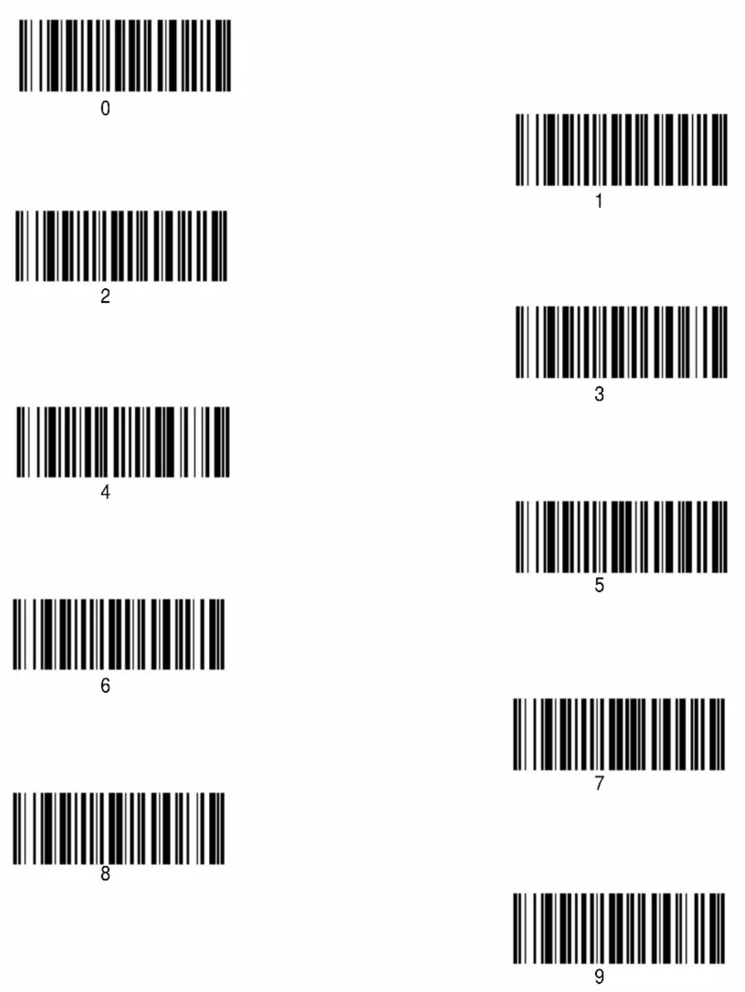
Programming Chart

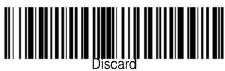
Hand Held Products, Inc.
700 Visions Drive
P.O. Box 208
Skaneateles Falls, NY 13153-0208

- DISCLAIMER
- STATEMENT OF AGENCY COMPLIANCE
- FCC CLASS B COMPLIANCE STATEMENT
- CANADIAN NOTICE
- UL AND CUL STATEMENT
- LED SAFETY STATEMENT
- TÜV STATEMENT
- C-TIC STATEMENT
- PATENTS
- CHAPTER 1 - GETTING STARTED
- CHAPTER 2 - TERMINAL INTERFACES
- CHAPTER 3 - OUTPUT
- CHAPTER 4 - DATA EDITING
- CHAPTER 5 - DATA FORMATTING
- CHAPTER 6 - SECONDARY INTERFACE
- CHAPTER 7 - SYMBOLOGIES
- CHAPTER 8 - CLONING
- CHAPTER 9 - VISUAL MENU
- CHAPTER 10 - INTERFACE KEYS
- CHAPTER 11 - UTILITIES
- CHAPTER 12 - SERIAL PROGRAMMING COMMANDS
- CHAPTER 13 - PRODUCT SPECIFICATIONS
- CHAPTER 14 - MAINTENANCE
- CHAPTER 15 - CUSTOMER SUPPORT
- TYPICAL APPLICATIONS FOR THE 3900
- ABOUT THIS MANUAL
- UNPACKING THE SCANNER
- CONNECTING THE SCANNER WHEN POWERED BY HOST (KEYBOARD WEDGE)
- MOUNTING INFORMATION FOR THE 3900
- MOUNTING INFORMATION, CONTINUED
- SPECULAR ZONE
- PLUG AND PLAY
- OPTION
- SETTING
- IBM 4683 PORTS 5B, 9B, AND 17 INTERFACE
- SYMBOLOGY
- SUFFIX
- USB INTERFACE
- OCIA INTERFACE
- NCR OCIA SHORT FORMAT (8 BIT) INTERFACE
- NCR OCIA LONG FORMAT (9 BIT) INTERFACE
- PREFIX
- NIXDORF OCIA INTERFACE
- SERIAL WEDGE
- KEYBOARD WEDGE CONNECTION
- TERMINAL ID
- KEYBOARD COUNTRY
- KEYBOARD STYLE
- KEYBOARD MODIFIERS
- SERIAL PORT CONNECTION
- BAUD RATE
- RS-232 WORD LENGTH: DATA BITS, STOP BITS, AND PARITY
- RS-232 HANDSHAKING
- WAND EMULATION CONNECTION
- WAND EMULATION TRANSMISSION RATE
- WAND EMULATION POLARITY
- WAND EMULATION IDLE
- PDF417 WAND EMULATION
- DATA BLOCK SIZE
- DELAY BETWEEN BLOCKS
- OVERALL CHECKSUM
- SCAN RATE
- BEEPER VOLUME
- BEEPER TONE
- SCAN VOTING
- REDUCE QUIET ZONE
- REREAD DELAY
- GOOD READ DELAY
- TRIGGER MODE
- PREFIX/SUFFIX OVERVIEW
- POINTS TO KEEP IN MIND
- TO ADD A PREFIX OR SUFFIX
- EXAMPLE: ADD A SUFFIX TO A SPECIFIC SYMBOLOGY
- TO CLEAR ONE OR ALL PREFIXES OR SUFFIXES
- TO ADD A CARRIAGE RETURN SUFFIX TO ALL SYMBOLOGIES
- ASCII CONVERSION CHART (CODE PAGE 1252)
- FUNCTION CODE TRANSMIT
- INTERCHARACTER, INTERFUNCTION, AND INTERMESSAGE DELAYS
- INTERCHARACTER DELAY
- USER SPECIFIED INTERCHARACTER DELAY
- INTERFUNCTION DELAY
- INTERMESSAGE DELAY
- DATA FORMAT EDITOR INTRODUCTION
- TO ADD A DATA FORMAT
- STEP 4. CODE I.D
- STEP 5. LENGTH
- STEP 6. EDITOR COMMANDS
- OTHER PROGRAMMING SELECTIONS
- CLEAR ONE DATA FORMAT
- SAVE
- DISCARD
- DATA FORMAT EDITOR COMMANDS
- SEND COMMANDS
- MOVE COMMANDS
- SEARCH COMMANDS
- MISCELLANEOUS COMMANDS
- DATA FORMATTER
- ALTERNATE DATA FORMATS
- SECONDARY CODE 39 WAND EMULATION
- SECONDARY RS-232 CONNECTION
- SECONDARY NON DECODED OUTPUT LASER EMULATION
- NON DECODED OUTPUT LASER EMULATION TRANSMISSION RATE
- NON DECODED OUTPUT LASER EMULATION POLARITY
- NON DECODED LASER EMULATION IDLE
- DISABLING THE SECONDARY INTERFACE
- SECONDARY TRIGGER MODE
- INTRODUCTION
- ALL SYMBOLOGIES
- MESSAGE LENGTH DESCRIPTION
- CODABAR
- START/STOP CHARACTERS
- CODABAR (CONTINUED)
- CHECK CHARACTER
- CONCATENATION
- CODABAR MESSAGE LENGTH
- CODE 39
- CODE 39, CONTINUED
- CODE 39 MESSAGE LENGTH
- CODE 39 APPEND
- BASE 32
- FULL ASCII
- INTERLEAVED 2 OF 5
- CHECK DIGIT
- INTERLEAVED 2 OF 5, CONTINUED
- INTERLEAVED 2 OF 5 MESSAGE LENGTH
- STRICT DECODING
- CODE 93
- CODE 93 MESSAGE LENGTH
- CODE 2 OF 5
- CODE 2 OF 5 MESSAGE LENGTH
- IATA CODE 2 OF 5
- IATA CODE 2 OF 5 MESSAGE LENGTH
- MATRIX 2 OF 5
- MATRIX 2 OF 5 MESSAGE LENGTH
- CODE 11
- CHECK DIGITS REQUIRED
- CODE 11 MESSAGE LENGTH
- CODE 128
- SUBSTITUTION
- CODE 128 MESSAGE LENGTH
- TELEPEN
- TELEPEN OUTPUT
- TELEPEN MESSAGE LENGTH
- UPCA
- NUMBER SYSTEM
- UPC A, CONTINUED
- ADDENDA
- ADDENDA REQUIRED
- ADDENDA SEPARATOR
- UPC STRICT DECODING
- UPC E
- UPC E0 AND UPC E1
- UPC E EXPAND
- UPC E, CONTINUED
- EAN/JAN 13
- EAN/JAN 13, CONTINUED
- ISBN ENABLE
- EAN/JAN 8
- EAN/JAN 8, CONTINUED
- MSI
- MSI, CONTINUED
- MSI MESSAGE LENGTH
- PLESSEY
- PLESSEY MESSAGE LENGTH
- RSS-14
- RSS LIMITED
- RSS EXPANDED
- RSS EXPANDED MESSAGE LENGTH
- CHINA POST CODE
- CHINA POST MESSAGE LENGTH
- PDF417
- PDF417 MESSAGE LENGTH
- PDF417, CONTINUED
- SHOW GLI BLOCKS
- SCAN DIAGNOSTICS
- PDF LEARN MODE
- MICROPDF417
- MICROPDF417 MESSAGE LENGTH
- EAN·UCC COMPOSITE SYMBOLOGY
- EAN·UCC COMPOSITE
- ENABLE UPC/EAN VERSION
- EAN·UCC COMPOSITE SYMBOLOGY, CONTINUED
- EAN•UCC COMPOSITE CODE MESSAGE LENGTH
- PROCEDURE
- VISUAL MENU INTRODUCTION
- VISUAL MENU OPERATIONS
- TEMPORARY VISUAL MENU CONFIGURATION
- INSTALLING VISUAL MENU FROM THE WEB
- UPGRADING USB FIRMWARE
- KEYBOARD FUNCTION RELATIONSHIPS
- SUPPORTED INTERFACE KEYS
- SUPPORTED
- INTERFACE KEYS APPLE MAC/IMAC
- TO ADD A TEST CODE I.D. PREFIX TO ALL SYMBOLOGIES
- SHOW SOFTWARE REVISION
- SHOW DATA FORMAT
- SPECULAR EFFECT REDUCTION
- SERIAL PROGRAMMING COMMANDS
- CONVENTIONS
- MENU COMMAND SYNTAX
- QUERY COMMANDS
- TAG FIELD USAGE
- SUBTAG FIELD USAGE
- DATA FIELD USAGE
- CONCATENATION OF MULTIPLE COMMANDS
- RESPONSES
- EXAMPLES OF QUERY COMMANDS
- TRIGGER COMMANDS
- RESETTING THE FACTORY SETTINGS
- STANDARD CABLE PINOUTS
- LASER OUTPUT ONLY (LASER COMPATIBLE BAR IMAGE)
- KEYBOARD WEDGE
- WAND EMULATION
- STANDARD CABLE PINOUTS (PRIMARY INTERFACE CABLES) SERIAL OUTPUT
- STANDARD CABLE PINOUTS USB
- REPAIRS
- MAINTENANCE
- CLEANING THE SCANNER'S WINDOW
- CAUTION
- INSPECTING CORDS AND CONNECTORS
- REPLACING THE INTERFACE CABLE
- TO REPLACE THE INTERFACE CABLE
- TROUBLESHOOTING
- PRODUCT SERVICE AND REPAIR
- NORTH AMERICA
- AMÉRICA LATINA
- EUROPE, MIDDLE EAST, AND AFRICA
- ASIA PACIFIC
- JAPAN
- ONLINE PRODUCT SERVICE AND REPAIR ASSISTANCE
- TECHNICAL ASSISTANCE
- NORTH AMERICA/CANADA
- ONLINE TECHNICAL ASSISTANCE
- LIMITED WARRANTY
- SAMPLE SYMBOLS
Brand : HONEYWELL
Model : 3800PDF
Category : Barcode scanners