
HD7100 - Video projector OPTOMA - Free user manual and instructions
Find the device manual for free HD7100 OPTOMA in PDF.


| Product Type | Video Projector |
| Brand | Optoma |
| Model | HD7100 |
| Display Technology | DLP |
| Native Resolution | 1920 x 1080 (Full HD) |
| Brightness | 3000 ANSI Lumens |
| Contrast Ratio | 20,000:1 |
| Lamp Type | P-VIP |
| Lamp Life (Normal) | 4,000 hours |
| Lamp Life (Eco) | 10,000 hours |
| Projection Lens | F/2.5-2.78, f=22.3-26.9mm |
| Zoom Ratio | 1.2x |
| Keystone Correction | Vertical ±40° |
| Inputs | HDMI, VGA, Composite, S-Video, USB |
| Audio | Built-in 2W speaker |
| Power Supply | 100-240V AC, 50/60Hz |
| Power Consumption | 230W (Normal), 170W (Eco) |
| Dimensions (W x D x H) | 324 x 234 x 107 mm |
| Weight | 2.5 kg |
| Noise Level | 30 dB (Normal), 25 dB (Eco) |
| Cleaning | Air filter cleaning every 100 hours |
| Safety | Automatic shutdown after 30 minutes idle |
Frequently Asked Questions - HD7100 OPTOMA
User questions about HD7100 OPTOMA
0 question about this device. Answer the ones you know or ask your own.
Ask a new question about this device
Download the instructions for your Video projector in PDF format for free! Find your manual HD7100 - OPTOMA and take your electronic device back in hand. On this page are published all the documents necessary for the use of your device. HD7100 by OPTOMA.
USER MANUAL HD7100 OPTOMA
natural_image
White projector with visible lens and control buttons (no text or symbols)Safety Information
The lightning flash with arrowheard within an equilateral triangle is intended to alert the user to the presence of uninsulated “dangerous voltage” within the product’s enclosure that may be of sufficient magnitude to constitute a risk of electric shock to persons.

The exclamation point within an equilateral triangle is intended to alert the user to the presence of import operating and maintenance (servicing) instructions in the literature accompanying the appliance.
WARNING: TO REDUCE THE RISK OF FIRE OR ELECTRIC SHOCK, DO NOT EXPOSE THIS APPLIANCE TO RAIN OR MOISTURE. DANGEROUS HIGH VOLTAGES ARE PRESENT INSIDE THE ENCLOSURE. DO NOT OPEN THE CABINET. REFER SERVICING TO QUALIFIED PERSONNEL ONLY.
Class B emissions limits
This Class B digital apparatus meets all requirements of the Canadian Interference-Causing Equipment Regulations.
Important Safety Instruction
- Read these instructions – before using this projector.
- Keep these instructions – for future reference.
- Follow all instructions.
- Install in accordance with the manufacturer's instructions
A. Do not block any ventilation openings
To ensure reliable operation of the projector and to protect it from overheating, put the projector in a position and location that will not interfere with its proper ventilation. For example, do not place the projector on a bed, sofa, carpet, or similar surface that may block the ventilation openings. Do not put it in an enclosure, such as a bookcase or a cabinet that may keep air from flowing through its ventilation openings.
B. Do not use this projector near water or moisture. To reduce the risk of fire or electric shock, do not expose the projector to rain or moisture.
C. Do not install near any heat sources, such as radiators, heaters, stoves or other apparatus (including amplifiers) that produce heat.
- Clean only with a dry cloth.
- Only use attachments/accessories specified by the manufacturer.
- Refer all servicing to qualified service personnel. Servicing is required when the projector has been damaged in any way:
■ Such as power supply cord or plug is damaged.
Liquid has been spilled or objects have fallen into the apparatus.
The projector has been exposed to rain or moisture, does not operate normally, or has been dropped.
Do not attempt to service this projector yourself. Opening or removing covers may expose you to dangerous voltages or other hazards. Please call Optoma to be referred to an authorized service center near you.
-
Do not let objects or liquids enter the projector – as they may touch dangerous voltage points or short-out parts that could result in a fi re or electric shock.
-
See projector enclosure for safety related markings.
-
The projector should not be adjusted or repaired by anyone except properly qualified service personnel.
Do:
■ Turn off the product before cleaning.
■ Use a soft cloth moistened with mild detergent to clean the display housing.
■ Disconnect the power plug from AC outlet if the product is not being used for a long period of time.
Don't:
■ Block the ventilation slots and openings on the unit
■ Use abrasive cleaners, waxes or solvents to clean the unit.
■ Use under the following conditions:
- In extremely hot, cold or humid environments.
- In areas susceptible to excessive dust and dirt.
- Near any appliance that generates a strong magnetic field.
- In direct sunlight.

Please follow all warnings, precautions and maintenance as recommended in this user's guide.
Warning- Do not look into the projector's lens when the lamp is on. The bright light may hurt your eyes.
■ Warning- To reduce the risk of fire or electric shock, do not expose this projector to rain or moisture.
Warning- Please do not open or disassemble the projector as this may cause electric shock.
Warning- When replacing the lamp, please allow unit to cool down, and follow all replacement instructions. See page 39.
Warning- This projector will detect the life of the lamp itself. Please be sure to change the lamp when it shows warning messages.
Warning- Reset the "Lamp Reset" function from the on-screen display Options|Lamp Settings" menu after replacing the lamp module (refer to page 33).
Warning- When switching the projector off, please ensure the cooling cycle has been completed before disconnecting power. Allow 90 seconds for the projector to cool down.
Warning- Do not use lens cap when projector is in operation.
Warning- When the lamp is approaching to the end of its life time, the message "Replacement suggested" will show on the screen. Please contact your local reseller or service center to change the lamp as soon as possible.
Eye Safety Warnings
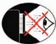
Avoid staring directly into the projector beam at all times.
Minimize standing facing into the beam. Keep your back to the beam as much as possible.
A stick or laser pointer is recommended to avoid the need for the user to enter the beam.
■ Ensure that projectors are located out of the line of sight from the screen to the audience; this ensures that, when presenters look at the audience, they do not also have to stare at the projector lamp. The best way to achieve this is by ceiling-mounting rather than floor or table-mounting the projector.
When projector is used in a classroom, adequately supervise students when they are asked to point out something on the screen.
In order to minimize the lamp power needed, use room blinds to reduce ambient light levels.
Contents
Preface 1
Notices 2
Introduction
Package Contents 7
Features 8
Components 9
Projector (Front and Top View) 9
Projector (Rear View).... 10
Remote Control 11
Using the Remote Control 12
Available Range of the Remote Control 12
Inserting the Batteries 12
Connections and Setup
Connecting the Projector to Other Devices 14
Before Setting Up.... 14
Connecting the Power Cord 14
Connecting to Video Equipment.... 15
Connecting to Component Video Equipment ..... 16
Connecting Using the DVI Cable 16
Connecting Using a DVI-D to HDMI Cable...... 17
Connecting the Projector to a Computer 18
Connecting the Cables 19
"Plug and Play" Function 19
Using the Adjustment Feet 20
Adjusting the Lens.... 21
Using the Lens Shift 21
Setting up the Screen.... 22
Screen Size and Projection Distance 23
Projection from behind the screen 25
Basic Operation
Image Projection 28
Basic Procedure.... 28
Selecting the On-screen Display Language ..... 30
Menu Bar Items 31
Using the Menu Screen.... 33
Menu Selections (Adjustments) 33
Adjusting the Image.... 34
Adjusting Computer Images 38
Easy to Use Functions
Selecting the Picture Display Mode.... 40
H-V Position Function.... 43
H-V Keystone Function 44
White Enhance 45
Selecting the Economy Mode.... 45
Setting the Power Save.... 45
Automatic Power Off Function 46
Source Select 46
OSD Timeout 47
OSD Blending.... 48
Reversing/Inverting Projected Images.... 48
Setting the Projection Mode 48
Deinterlace 49
Reset 50
Lamp Timer Reset 50
Status Screen.... 51
Factory reset 51
Appendix
Maintenance.... 54
Cleaning the Ventilative Holes 55
Cleaning the Ventilative Holes 55
About the Lamp 56
Caution Concerning the Lamp 56
Replacing the Lamp 56
Temperature LED (Over Temperature).... 56
Removing and Installing the Lamp Unit....57
Resetting the Lamp Timer 58
Connecting Pin Assignments 59
Computer Compatibility Chart 60
Video Compatibility Chart....61
Troubleshooting.... 62
Dimensions.... 64
Introduction
Package Contents
Open the package and ensure that you have the following items:
Strandard Accessories
Remote Control
Two "AA" Batteries
Power Cord
Composite Video Cable (3M)
Component Video Cable (3M)
RS-232C cable 3M
Optional Accessories
HD 15-pin VGA to HD 15-pin VGA cable
RS-232C cable (3M)
DVI-D to DVI-D cable (3M)
DVI-D to HDMI cable (3M)
Ceiling mount package

Note
- Some of the cables may not be available depending on the region. Please check with your nearest authorized dealer.
If anything is missing or appears damaged, contact your dealer immediately.
Features
- Newly developed DMD™ chip provides significantly improved optical efficiency and excellent contrast ratio.
- Newly developed LVDS (Low voltage differential signal) chip eliminates color breaking phenomena common with previous generation DLP™ projectors.
- The 250W high-output lamp gives high color purity and brightness. Natural images are possible with excellent color reproduction and powerful expression capabilities.
- Latest image quality circuitry gives you vivid images.
- New I/P conversion algorithm enhances motion.
- Extensive improvements in jagged edges and slanted lines in moving images.
- New Edge Up-Scaling.
- As a result of reducing jagged edges and flickering when up-scaling edges of slanted lines, even signals not reaching a panel resolution of 480I/P can be projected by converting them to 1280 × 720 resolution images.
- New Film mode.
• 3:2 pull-down enhancement for 480I, 576I and HDTV 1080I signals. - Use of a DVI/HDCP terminal enables all processes from input to signal processing and projecting to be performed digitally. All-digital projection does not suffer the data loss of analog conversion. Home theaters using HTPC are supported.
Components
Projector (Front and Top View)
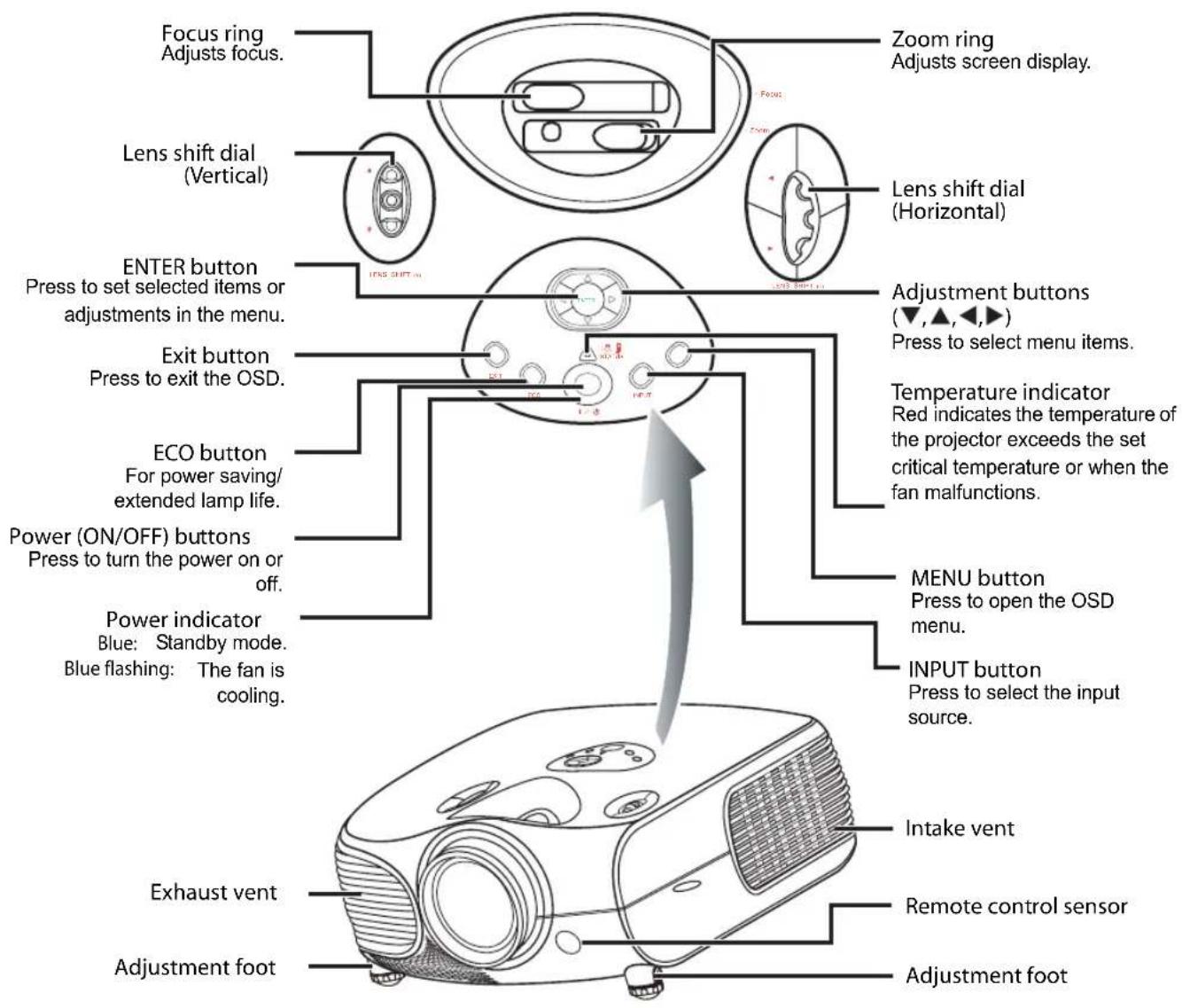
Temperature indicator
On the top in projector control panel, there is a temperature warning LED. If the projector overheats due to a dirty filter or other issue, the LED will flash and the lamp will shut off. Following a 90 second cooling off period, please restart the projector. If the unit still is not operating normally, the unit will require immediate service.
Projector (Rear View)
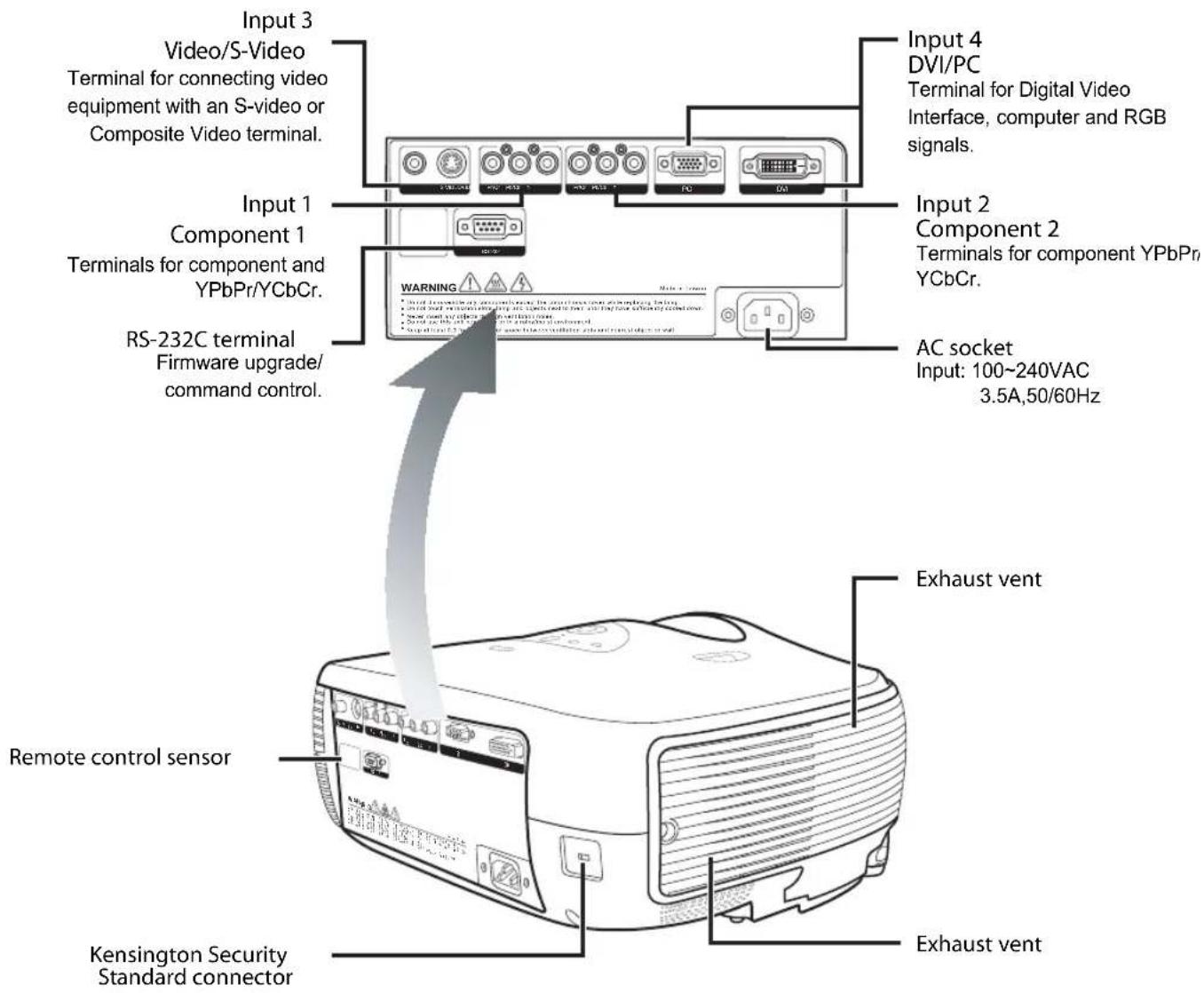
Using the Kensington Lock

This projector has a Kensington Security Standard connector for use with a Kensington MicroSaver Security System. To use this security feature, please refer to your Kensington Lock.
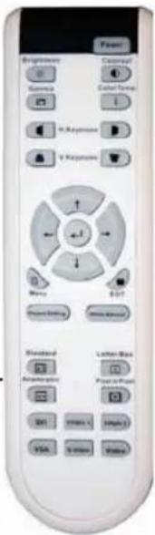
Remote Control
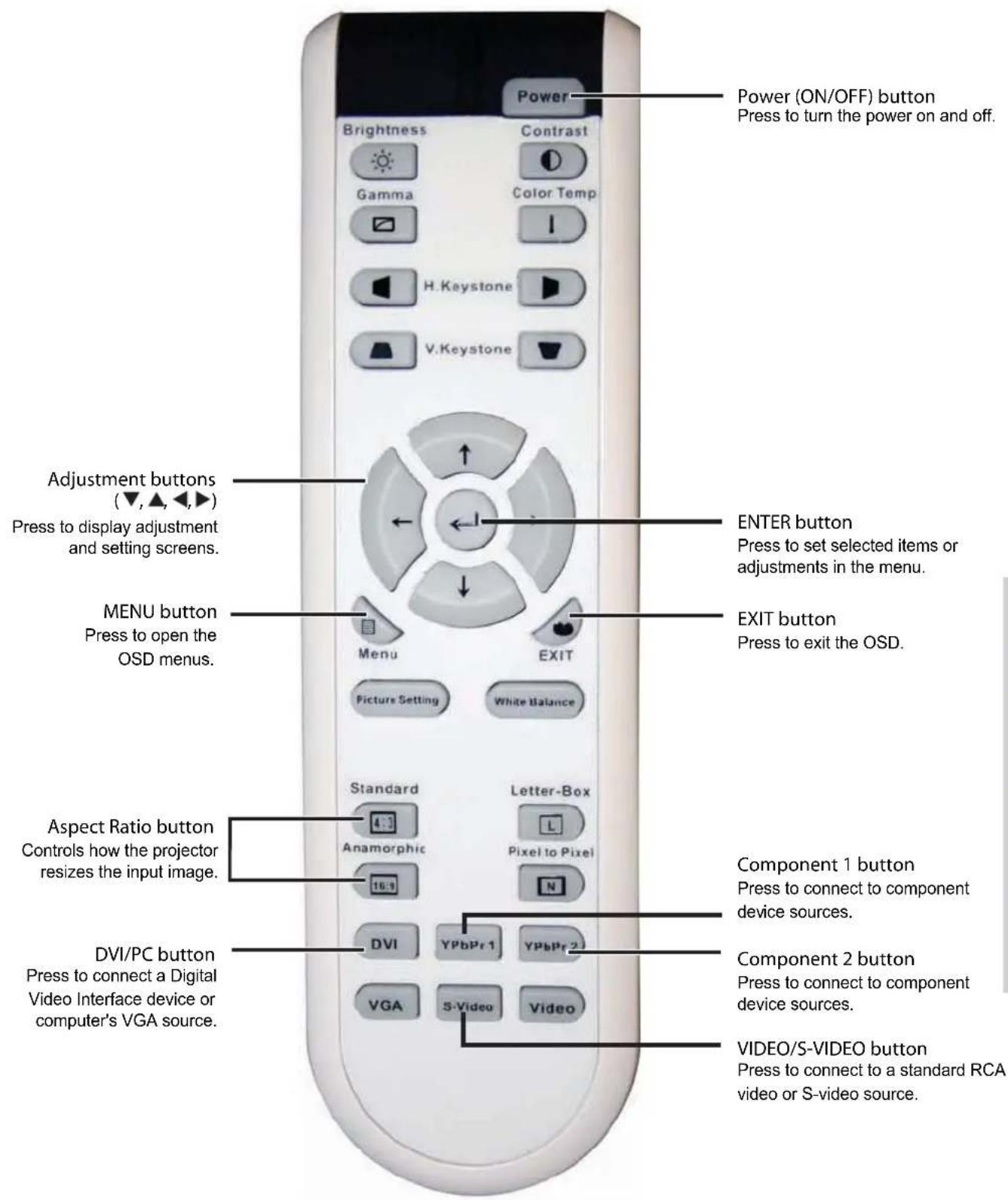
Using the Remote Control
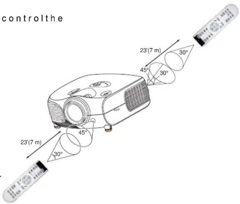
Available Range of the Remote Control
■ Theremote control can be used to control the projector within the ranges shown in the illustration.

Note
- The signal from the remote control can be reflected by the screen. You can control the projector when it is behind you by bouncing the signal off the screen.
When using the remote control:
- Do not drop it, or expose it to moisture or high temperature.
- The remote control may not function correctly under fluorescent lamps. Operate the projector away from fluorescent lamps.
Inserting the Batteries
The batteries (two AA) are included in the package.
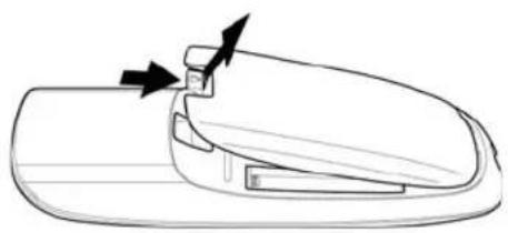
1 Press down the tab on the cover and pull the cover towards the direction of the arrow.
2 Insert the included batteries. Make sure the polarities correctly match the and marks inside the battery compartment.
3 Insert the lower tab of the cover into the opening, and press down the cover until it clicks in place.
natural_image
Line drawing of a car door handle with arrows indicating movement or force (no text or symbols)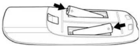
natural_image
Top-down schematic of a vehicle showing internal compartments with arrows indicating direction (no text or symbols)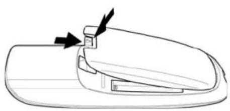
natural_image
Line drawing of a car door handle with a clip and arrow indicator (no text or symbols)Connections and Setup
Connecting the Projector to Other Devices
Before Setting Up

Note
- Before connecting, turn off both the projector and the devices to be connected. After making all connections, turn on the projector first and then the other devices.
When connecting a computer, be sure that the computer is the last device turned on, after all connections are made. - Read the operation manuals of the devices to be connected before making connections.
This projector can be connected to
Video equipment:
■ A VCR, Laser disc player or other video equipment.
■ A DVD player or DTV* decoder.
*DTV is the umbrella term used to describe the new digital television system.
A computer, using:
■ A HD 15-pin VGA to HD 15-pin VGA cable (sold separately), or
■ A DVI-D to DVI-D cable (sold separately), or
■ An RS-232C cable.
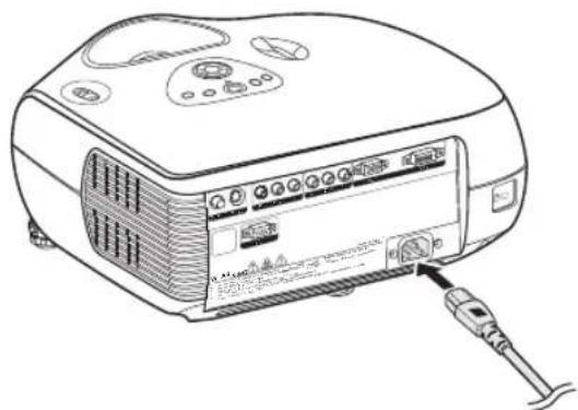
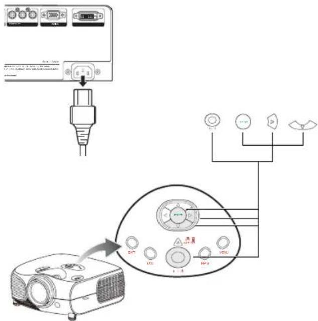
Connecting the Power Cord
Plug the supplied power cord into the AC socket on the rear of the projector.
Supplied accessory
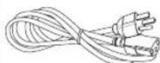
Power cord
natural_image
Line drawing of a portable electronic device with ports and a cable inserted (no text or symbols visible)Connecting to Video Equipment
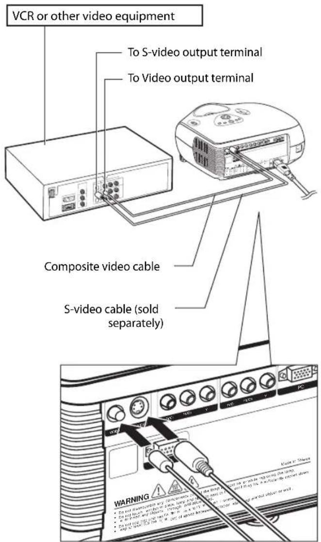
Using an S-video or a Composite Video Cable (INPUT 3)
Using an S-video or a composite video cable, a VCR, laser disc player or other video equipment can be connected to the INPUT 3 terminals.

Notes
- The INPUT 3 (S-VIDEO) terminal uses a video signal system in which the picture is separated into color and luminance signals to give a higher-quality image. To view the higher-quality image, use a commercially available S-video cable to connect the INPUT 3 terminal on the projector and the S-video output terminal on the video equipment.
Connecting to Component Video Equipment
Using a Component Cable (INPUT 1 or 2)
Use a component cable when connecting component video equipment such as DVD players and DTV* decoders to the INPUT 1 or 2 terminals.
*DTV is an umbrella term used to describe the new digital television system.

Note
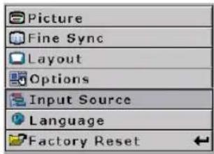
- When connecting the projector to video equipment in this way, set "Input Source" to "Component 1 or 2" in the "Main" menu.
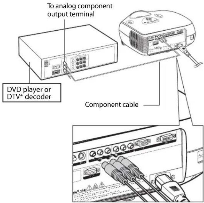
The device's component jacks may be labeled Y, CB and CR. Connect each jack as shown below.
| Projector Y | P B | P R | |
| DVD player or DTV decoder | Y | C B | C R |
Connecting Using the DVI Cable
Use the DVI cable when connecting video equipment with DVI output such as DVD players and DTV* decoders to the INPUT 4 terminal.

Note
- Select the input signal type of the video equipment.
Optional accessory
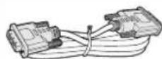
DVI-D cable
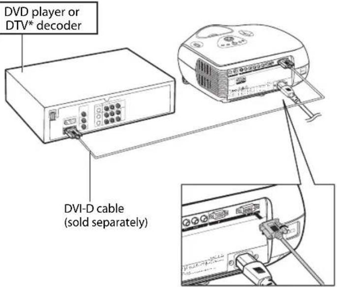
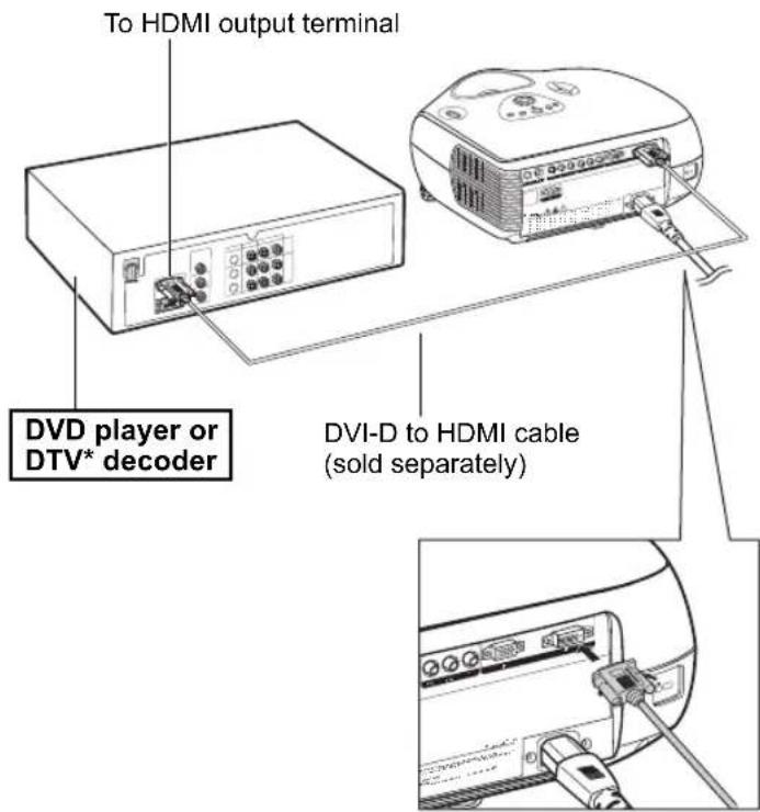
Connecting Using a DVI-D to HDMI Cable
Use a DVI to HDMI cable when connecting HDMI video equipment such as DVD players to the INPUT 4 terminal.
1 Connect a DVI-D to HDMI cable to the projector.
- Secure the connectors by tightening the thumbscrews.
2 Connect the above cable to the video equipment.

Note
- Select the input signal type of the video equipment.
Optional accessory
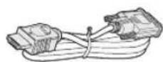
DVI-D to HDMI cable
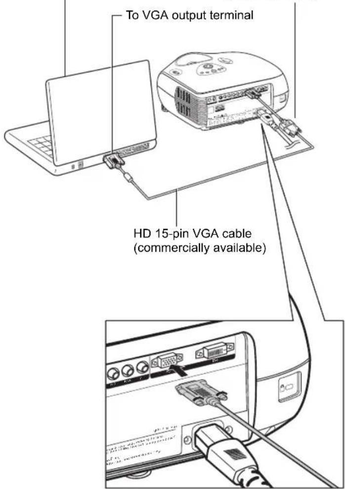
Connecting the Projector to a Computer
Connect the projector to the computer using an HD 15-pin VGA cable.
- Secure the cable connectors by tightening the screws on both sides of the plug.
Optional accessory
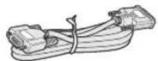
HD 15-pin VGA cable

Notes
- See page 60 "Computer Compatibility Chart" for a list of computer signals compatible with the projector. Using computer signals other than those listed may cause some of the functions not to work.
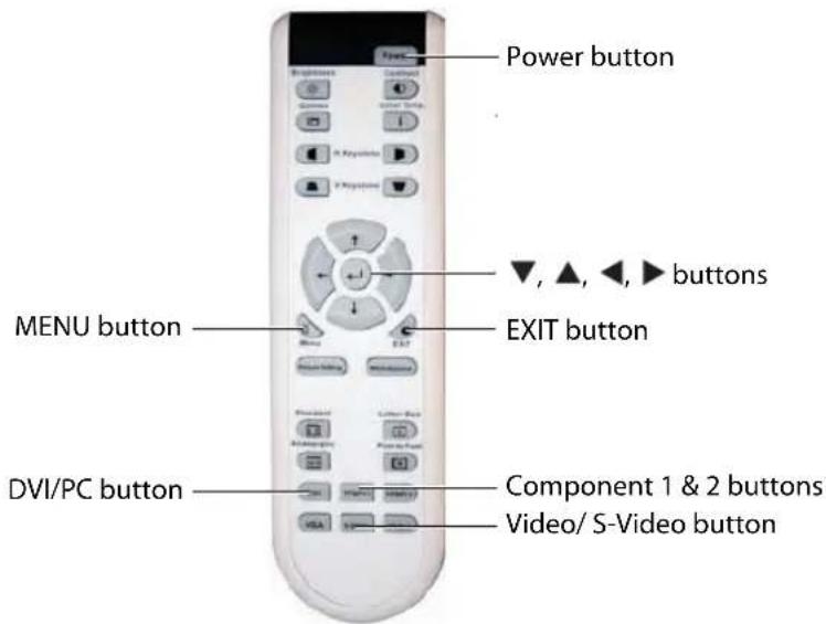
- When connecting the projector to a computer using an HD 15-pin VGA cable, set the "Input Source" to "PC" in the "Main" menu, or select RGB mode by pressing the DVI/PC button on the remote control.
- A Macintosh adaptor may be required for use with some Macintosh computers. Contact your nearest authorized service center or dealer.
- Depending on the computer you are using, an image may not be projected unless the signal output setting of the computer is switched to the external output. Refer to the computer operation manual for switching the computer signal output settings.
Notebook Computer
HD 15-pin VGA cable (sold separately)
Connect the projector to the computer using a DVI-D cable (sold separately).

Note
- Select the input signal type of the video equipment.
Optional accessory
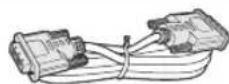
DVI-D cable
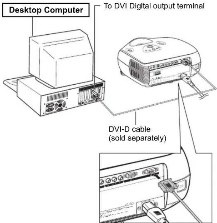
Connecting the Cables
■ Connect the cable making sure that it fits correctly into the terminal. Secure the connectors by tightening the screws on both sides of the plug.
■ Do not remove the ferrite cores attached to the cable.

"Plug and Play" Function
This projector is compatible with VESA-standard DDC 1/DDC 2B. The projector and a VESA DDC compatible computer automatically send settings, allowing for quick and easy setup.
■ Before using the "Plug and Play" function, be sure to turn on the projector first and the computer last.

Note
- The DDC "Plug and Play" function of this projector operates only when used in conjunction with a VESA DDC compatible computer.
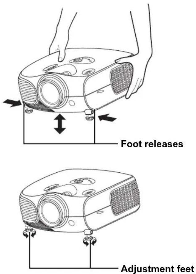
Using the Adjustment Feet
Use the adjustment feet to level the projector when it is placed on an uneven surface or when the screen is slanted.
The projection can be made higher by adjusting the projector when it is in a location lower than the screen.
1 Press the foot releases and lift the projector to the desired angle.
2 Remove your hands from the foot releases. When the adjustment feet have locked in position, place the projector down.
- If the screen is at an angle, the adjustment feet can be used to adjust the angle of the image.

Notes
- The projector is adjustable up to approximately 11 degrees from the standard position.
- When the height of the projector is adjusted, the image may become distorted (keystoned), depending on the relative positions of the projector and the screen. See page 44 for details on keystone correction.

Info
- When lowering the projector, be careful not to catch your fingers in the area between the adjustment foot and the projector.
Adjusting the Lens
Adjust the lens using the focus and zoom rings to correct the image.
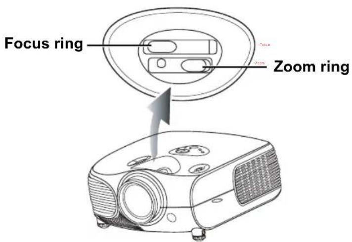
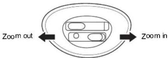
1 Adjust zoom by rotating the zoom ring.
Zoom ring
flowchart
graph TD
    A["Zoom out"] --> B["Arrow Left"]
    B --> C["Zoom in"]
    C --> D["Arrow Right"]
2 Adjust focus by moving the focus ring.
Focus ring
natural_image
Simple diagram of a device with two circular components and bidirectional arrows indicating flow or interaction (no text or symbols)Using the Lens Shift
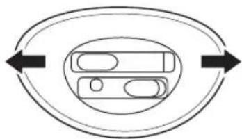
The height and width of the projected image can be adjusted to be within the shift range of the lens by rotating the lens shift dial at the top of the projector.

Note
- Do not forcibly turn the lens shift dial beyond the range of the upper left and lower right positions. This may cause the projector to malfunction.
Lens shift dial (Vertical)
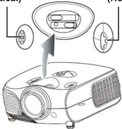
Lens shift dial (Horizontal)
Setting up the Screen
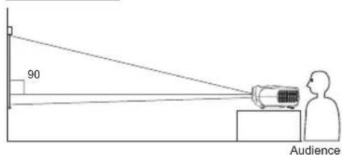
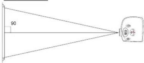
Position the projector perpendicular to the screen with all feet flat and level to achieve an optimal image.

Notes
- The projector lens should be perpendicular (square-on) to the screen. If the horizontal line passing through the lens center is not perpendicular to the screen, the image will be distorted, making viewing difficult.
- For an optimal image, position the screen so that it is not in direct sunlight or room light. Light falling directly on the screen washes out the colors, making viewing difficult. Close curtains and dim the lights when setting up the screen in a sunny or bright room.
- A polarizing screen cannot be used with this projector.
Standard Setup (Front Projection)
■ Place the projector at the required distance from the screen according to the desired picture size. (See page 23)
An Example of Standard Setup
Side View
Top View
- The distance from the screen to the projector depends on the size of the screen.
- The default setting can be used, when placing the projector in front of the screen. If the projected image is reversed or inverted, readjust the setting to "Front" for "PRJ Mode" in the "Options" menu.
- Place the projector so that an imaginary horizontal line that passes through the center of the lens is perpendicular to the screen.
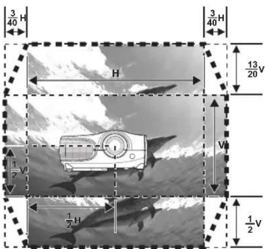

Notes
2D Lens Shift:
- The vertical display (Biggest) is (+13/20V / -1/2V) screen.
• The horizontal display (Biggest) is ±3/40 screen. (±15%) - It is recommended that images be projected onto the dashed line octagonal area for fine image quality.
- There is a tolerance of ± 3% in the formula above.
Screen Size and Projection Distance
When using a wide screen (16:9) project the image on the whole area of the 16:9 screen.
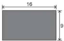

: Picture area
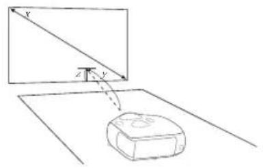
| Screen Size (16:9) Projection Distance | Distance from lens center to the lower edge of the image | |||||
| Diagonal | Width | Height | Max | Min | upper | lower |
| 300" (762 cm) | 261" (664 cm) | 147" (374 cm) | 37'6" (11.4 m) | 29'10" (9.1 m) | 0" (0 cm) | -12'3" (-374 cm) |
| 250" (635 cm) | 218" (553 cm) | 123" (311 cm) | 31'3" (9.5 m) | 24'11" (7.6 m) | 0" (0 cm) | -10'3" (-311 cm) |
| 200" (508 cm) | 174" (443 cm) | 98" (249 cm) | 24'12" (7.6 m) | 19'11" (6.1 m) | 0" (0 cm) | -8'2" (-249 cm) |
| 150" (381 cm) | 131" (332 cm) | 74" (187 cm) | 18'9" (5.7 m) | 14'11" (4.6 m) | 0" (0 cm) | -6'2" (-187 cm) |
| 133" (338 cm) | 116" (294 cm) | 65" (166 cm) | 16'7" (5.1 m) | 13'3" (4.0 m) | 0" (0 cm) | -5'5" (-166 cm) |
| 106" (269 cm) | 92" (234 cm) | 52" (132 cm) | 13'3" (4.0 m) | 10'7" (3.2 m) | 0" (0 cm) | -4'4" (-132 cm) |
| 100" (254 cm) | 87" (221 cm) | 49" (125 cm) | 12'6" (3.8 m) | 9'11" (3.0 m) | 0" (0 cm) | -4'1" (-125 cm) |
| 92" (234 cm) | 80" (204 cm) | 45" (115 cm) | 11'6" (3.5 m) | 9'2" (2.8 m) | 0" (0 cm) | -3'9" (-115 cm) |
| 84" (213 cm) | 73" (186 cm) | 41" (105 cm) | 10'6" (3.2 m) | 8'4" (2.5 m) | 0" (0 cm) | -3'5" (-105 cm) |
| 72" 183 cm) | 63" (159 cm) | 35" (90 cm) | 9'00" (2.7 m) | 7'2" (2.2 m) | 0" (0 cm) | -2'11" (-90 cm) |
| 60" (152 cm) | 52" (132 cm) | 29" (75 cm) | 7'6" (2.3 m) | 6'00" (1.8 m) | 0" (0 cm) | -2'5" (-75 cm) |
| 40" (102 cm) | 35" (89 cm) | 20" (50 cm) | 5'00" (1.5 m) | 4'00" (1.2 m) | 0" (0 cm) | -1'8" (-50 cm) |
The formula for screen size and projection distance
y1(max)=0.038089291x
y2(min)=0.030344196x
z1 (Upper) = 0
z2(lower)=1.245263549x
x: Screen size (diag.) (meter)
y: Projection distance (feet)
z: Distance from the lens center to the lower edge of the image (centimeter)

Notes
• There is a tolerance of ±3% in the formula above.
- Values with a minus (−) sign indicate the distance of the lens center below the bottom of the image.
When using a normal screen (4:3) project the image to the full horizontal width of the 4:3 screen.
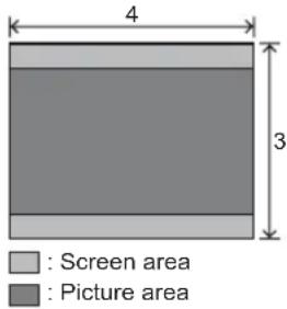
| Screen Size (4:3) Projection Distance | Distance from lens center to the lower edge of the image | |||||
| Diagonal | Width | Height | Max | Min | upper | lower |
| 250" (635 cm) | 200" (508 cm) | 150" (381 cm) | 28'8" (8.7 m) | 22'10" (7.0 m) | 0" (0 cm) | -9'5" (-286 cm) |
| 200" (508 cm) | 160" (406 cm) | 120" (305 cm) | 22'11" (7.0 m) | 18'3" (5.6 m) | 0" (0 cm) | -7'6" (-229 cm) |
| 150" (381 cm) | 120" (305 cm) | 90" (229 cm) | 17'2" (5.2 m) | 13'8" (4.2 m) | 0" (0 cm) | -5'8" (-171 cm) |
| 133" (338 cm) | 106" (270 cm) | 80" (203 cm) | 15'3" (4.6 m) | 12'2" (3.7 m) | 0" (0 cm) | -5'0" (-152 cm) |
| 106" (269 cm) | 85" (215 cm) | 64" (162 cm) | 12'2" (3.7 m) | 9'8" (3.0 m) | 0" (0 cm) | -4'0" (-121 cm) |
| 100" (254 cm) | 80" (203 cm) | 60" (152 cm) | 11'6" (3.5 m) | 9'2" (2.8 m) | 0" (0 cm) | -3'9" (-114 cm) |
| 92" (234 cm) | 74" (187 cm) | 55" (140 cm) | 10'7" (3.2 m) | 8'5" (2.6 m) | 0" (0 cm) | -3'5" (-105 cm) |
| 84" (213 cm) | 67" (171 cm) | 50" (128cm) | 9'8" (2.9 m) | 7'8" (2.3 m) | 0" (0 cm) | -3'2" (-96 cm) |
| 72" (183 cm) | 58" (146 cm) | 43" (110 cm) | 8'3" (2.5 m) | 6'7" (2.0 m) | 0" (0 cm) | -2'8" (-82 cm) |
| 60" (152 cm) | 48" (122 cm) | 36" (91 cm) | 6'11" (2.1 m) | 5'6" (1.7 m) | 0" (0 cm) | -2'3" (-69 cm) |
| 40" (102 cm) | 32" (81 cm) | 24" (61 cm) | 4'7" (1.4 m) | 3'8" (1.1 m) | 0" (0 cm) | -1'6" (-46 cm) |
The formula for screen size and projection distance
y1 (Max.) = 0.03466592x
x: Screen size (diag.) (meter)
y2 (Min.) = 0.0276352x
y: Projection distance (feet)
z1 (Upper) = 0
z: Distance from the lens center to the lower edge of the image (centimeter)
z2 (Lower) = 1.143x

Notes
- There is a tolerance of ± 3% in the formula above.
- Values with a minus (−) sign indicate the distance of the lens center below the bottom of the image.
Projection from behind the screen
Projecting a Reversed/Inverted Image
■ Place a translucent screen between the projector and the When using the default setting.
audience.
■ Set "PRJ Mode" to "Rear" in the "Options" menu.
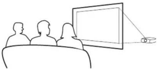
natural_image
Line drawing of three people watching a presentation on a screen, with a small object nearby (no text or symbols)▼On-screen Display
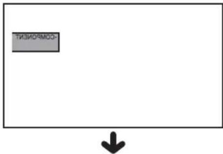
The image is reversed.
Projection using a mirror
■ Place a mirror (normal flat type) in front of the lens.
When using the default setting.
■ Set "PRJ Mode" to "Rear" in the "Options" menu, when the ▼ On-screen Display
mirror is placed on the side where the audience is.
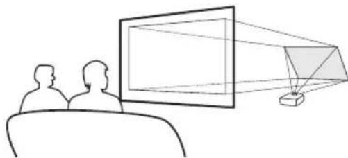
natural_image
Line drawing of two people watching a large screen with a light source, no text or symbols present▼On-screen Display
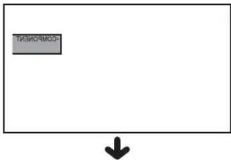
The image is reversed.

Info
- When using a mirror, be sure to carefully position both the projector and the mirror so that the light does not shine into the eyes of the audience.
Ceiling-mount setup
■ The optional ceiling-mount bracket is recommended for this installation.
■ Before mounting the projector, contact your nearest Authorized Service Center or Dealer to obtain the recommended ceiling-mount bracket (sold separately).
■ Adjust the position of the projector to match the distance (Z) from the lens center position to the lower edge of the image, when mounting the projector on the ceiling.
■ Invert the image by setting "Ceiling + Front" for "PRJ Mode" in the "Options Menu".
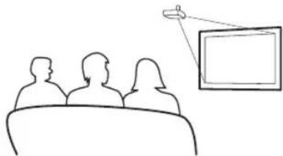
natural_image
Line drawing of a meeting with three people facing a screen (no text or symbols)When using the default setting.
▼On-screen Display
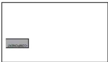

The image is reversed.
NOTES
natural_image
Line drawing of a projector with lens and control panel (no text or symbols)Basic Operation
Image Projection
Basic Procedure
Connect the required external equipment to the projector before following these procedures.

Info
- The preset language is English. To change the on-screen display to another language, reset the language according to the procedure on page 30.
1 Plug the power cord into the wall outlet.
- The power indicator illuminates blue, and the projector enters standby mode.
2 Press on the remote control or on the projector.
• The power indicator turns off.

Note
- The power indicator illuminates, indicating the status of the lamp. Blue: The power is ready. Blue blinking: The fan is cooling.
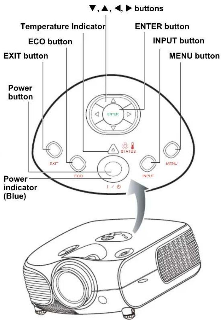
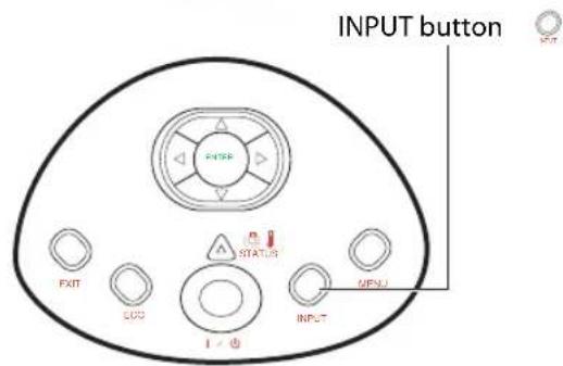
3 Press on the projector to
select the INPUT
mode.
About the INPUT modes
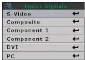
| S-Video | Use this option to select the S-Video input source. |
| Video | Use this option to select the composite video input source. |
| Component 1&2 | Use this option to select a YPbPr, SDTV, or HDTV component input source. |
| DVI | Use this option to select the DVI input source. |
| PC | Use this option to select the computer as an input source. |

Note
- When a signal is not received, "Searching" will be displayed.

Note
- If you select "Auto" as the input source, then the correct input source is selected automatically.
4 Press on the remote control
or ☐ on the projector. Press Enter to turn off the projector, when the confirmation message is displayed.

Note
- If you accidentally press power and do not want to turn off the projector, press Exit button or wait until the confirmation message disappears.
- Do not unplug the power cord during projection or cooling fan operation. This can cause damage due to the rise in internal temperature, as the cooling fan also stops.
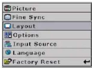
Main Menu
Selecting the On-screen Display Language
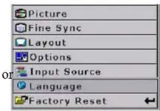
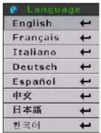
- The on-screen display language of the projector can be set to English, Français, Italiano, Deutsch, Español, 中文,日本語,한국어。
1 Press "MENU".
- The menu displays.
2 Press ← ▶ to select "Language".
3 Press ▲ or ▼ to select the desired language, then press
The selected language is set as the on-screen display.
4 Press "EXIT".
Main Menu
Menu Bar Items
This list shows the items that can be set in the projector.
■ Composite Video/S-Video, DVI Mode
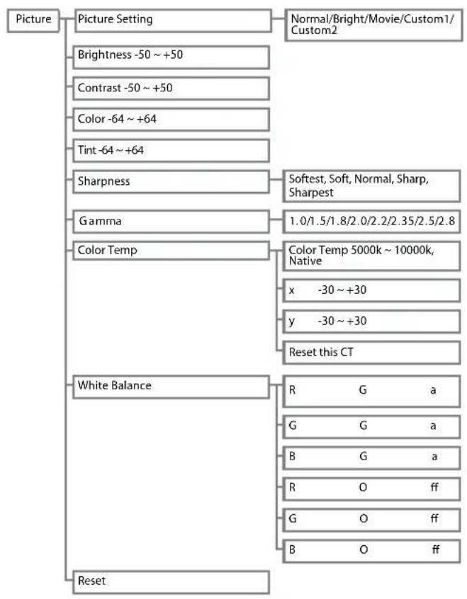
flowchart
graph TD
    A["Picture"] --> B["Picture Setting"]
    B --> C["Brightness -50 ~ +50"]
    B --> D["Contrast -50 ~ +50"]
    B --> E["Color -64 ~ +64"]
    B --> F["Tint -64 ~ +64"]
    B --> G["Sharpness"]
    G --> H["Gamma"]
    G --> I["Color Temp"]
    I --> J["White Balance"]
    I --> K["Reset"]

    C --> L["Normal/Bright/Movie/Custom1/Custom2"]
    D --> L
    E --> M["Softest, Soft, Normal, Sharp, Sharpest"]
    H --> N["1.0/1.5/1.8/2.0/2.2/2.35/2.5/2.8"]
    I --> O["x -30 ~ +30"]
    I --> P["y -30 ~ +30"]
    I --> Q["Reset this CT"]

    N --> R["R G a"]
    N --> S["G G a"]
    N --> T["B G a"]
    N --> U["R O ff"]
    N --> V["G O ff"]
    N --> W["B O ff"]
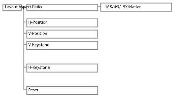
flowchart
graph TD
    A["Layout Aspect Ratio"] --> B["H-Position"]
    A --> C["V-Position"]
    A --> D["V-Keystone"]
    A --> E["H-Keystone"]
    A --> F["Reset"]
    G["16:9/4:3/LBX/Native"] --> A
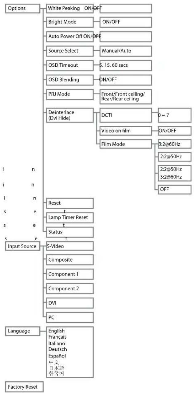
flowchart
graph TD
    A["Options"] --> B["White Peaking ON/OFF"]
    A --> C["Bright Mode ON/OFF"]
    A --> D["Auto Power Off ON/OFF"]
    A --> E["Source Select Manual/Auto"]
    A --> F["OSD Timeout 5.15.60 secs"]
    A --> G["OSD Blending ON/OFF"]
    A --> H["PRJ Mode Front/Front ceiling/Rear/Rear ceiling"]
    A --> I["Deinterlace (Dvi Hide) DCTI 0~7"]
    I --> J["Video on film ON/OFF"]
    I --> K["Film Mode 3:2@60Hz"]
    I --> L["2:2@50Hz"]
    I --> M["2:2@50Hz"]
    I --> N["3:2@60Hz"]
    I --> O["OFF"]
    P["i n"] --> Q["Reset"]
    R["i n"] --> Q
    S["i n"] --> T["Reset"]
    U["s e"] --> V["Lamp Timer Reset"]
    W["s e"] --> V
    X["s e"] --> Y["Status"]
    Z["Input Source"] --> AA["S-Video"]
    AB["Input Source"] --> AC["Composite"]
    AD["Input Source"] --> AE["Component 1"]
    AF["Input Source"] --> AG["Component 2"]
    AH["Input Source"] --> AI["DVI"]
    AJ["Input Source"] --> AK["PC"]
    AL["Language"] --> AM["English Français Italiano Deutsch Español 中文 日本語 한국어"]
    AN["Factory Reset"] --> AO["Output"]
■ PC/Component 1&2 Mode
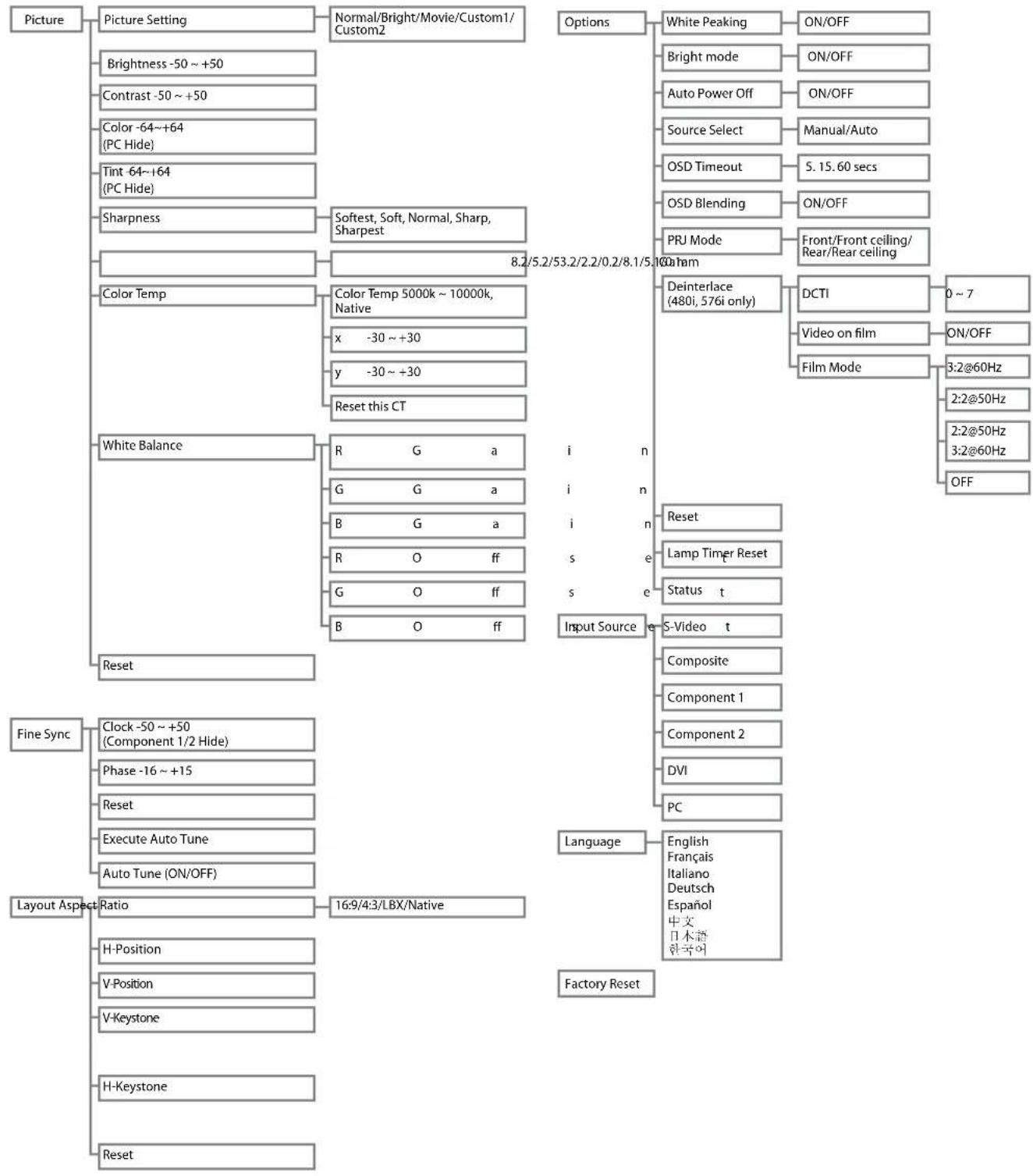
flowchart
graph TD
    A["Picture"] --> B["Picture Setting"]
    B --> C["Brightness -50 ~ +50"]
    C --> D["Contrast -50 ~ +50"]
    D --> E["Color -64~+64 (PC Hide)"]
    E --> F["Tint 64~+64 (PC Hide)"]
    F --> G["Sharpness"]
    G --> H["Softest, Soft, Normal, Sharp, Sharpest"]
    H --> I["8.2/5.2/53.2/2.2/0.2/8.1/5.10HAM"]
    I --> J["Color Temp"]
    J --> K["Color Temp 5000k ~ 10000k, Native"]
    K --> L["x -30 ~ +30"]
    L --> M["y -30 ~ +30"]
    M --> N["Reset this CT"]
    N --> O["White Balance"]
    O --> P["R G a"]
    P --> Q["G G a"]
    Q --> R["B G a"]
    R --> S["R O ff"]
    S --> T["G O ff"]
    T --> U["B O ff"]
    U --> V["Input Source e"]
    V --> W["S-Video t"]
    V --> X["Composite"]
    V --> Y["Component 1"]
    V --> Z["Component 2"]
    V --> AA["DVI"]
    V --> AB["PC"]
    V --> AC["Language"]
    AC --> AD["English Français Italiano Deutsch Español 中文 日本語 한국어"]
    AC --> AE["Factory Reset"]

    subgraph Inputs
        direction TB
        A --> A1["Options"]
        A1 --> A1a["White Peaking ON/OFF"]
        A1 --> A1b["Bright mode ON/OFF"]
        A1 --> A1c["Auto Power Off ON/OFF"]
        A1 --> A1d["Source Select Manual/Auto"]
        A1 --> A1e["OSD Timeout 5.15.60 secs"]
        A1 --> A1f["OSD Blending ON/OFF"]
        A1 --> A1g["PRJ Mode Front/Front ceiling/Rear/Rear ceiling"]
        A1 --> A1h["Deinterlace (480i, 576i only) DCTI 0 ~ 7"]
        A1 --> A1i["Video on film ON/OFF Film Mode 3:2@60Hz 2:2@50Hz 2:2@50Hz 3:2@60Hz OFF"]
    end
Using the Menu Screen
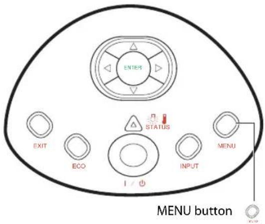
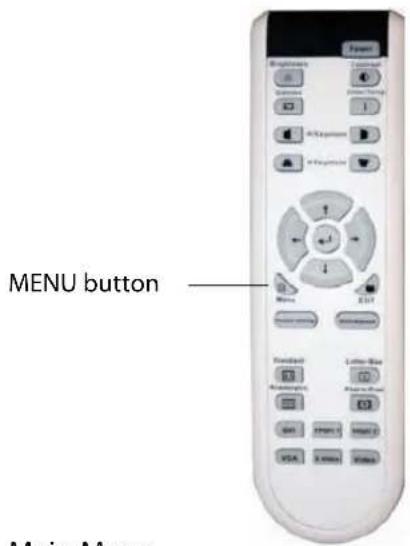
You can use the menu screens to adjust the image and projector settings. You can operate the menus from the projector or remote control using the following procedure.
MenuSelections (Adjustments)
1
Press 📄 on remote or

the keypad.
- Themenuscreenisdisplayed.

Note
- The "Picture" menuscreenforthe selectedinputmodeisdisplayed.
2
Press ▲ or ▼ to select the menu you want to adjust.
3
Press ▶ or ← to reach the Sub-menu and then press ▲ or ▼ to select the item you want to adjust.

Note
• Theselecteditemwillbehhighlighted.
4
Press ◀ or ▶ to adjust the item selected.
- Theadjustmentisstored.
5
Press EXIT to return to "Main MENU".
6
Press EXIT to close the menu screen.
Main Menu
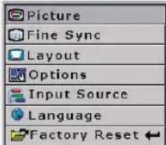
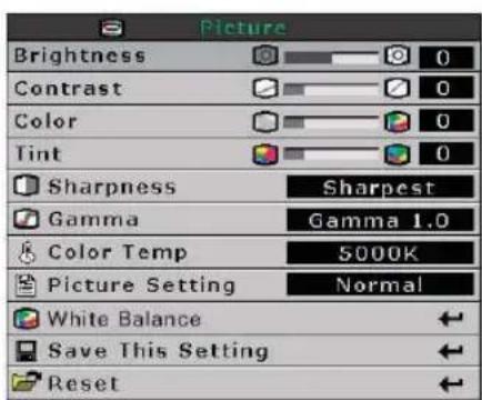

Adjusting the Image
You can adjust the image with the following procedure.
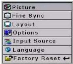
Main Menu
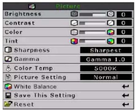
| Selected item Description |  | ||
| Brightness | Adjusts the brightness | Decreases brightness | Increases brightness |
| Contrast | Adjusts the contrast level | Decreases contrast | Increases contrast |
| Color | Adjusts the color intensity | Decreases color intensity | Increases color intensity |
| Tint Adjusts the tones Skin tones become purplish | Skin tones become greenish | ||
Brightness
Use this option to adjust the overall brightness of the image. Use in conjunction with contrast to fine-tune the display. The scale is from -50 to 50. The default setting is 0.

Contrast
Use this option to adjust the contrast of the image. Use this control in conjunction with contrast to fine-tune the display. The scale is from -50 to 50. The default setting is 0.

Color
Use this option to adjust the color intensity of the image.

Tint
Use this option to adjust the tint of your image. Press ▶ to make the image more green. Press ◀ to make the image more purple.

Sharpness
Use this option to adjust the clarity and focus of the image.

Color TEMP
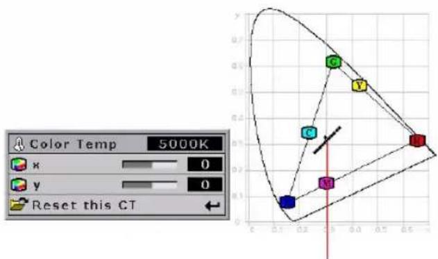
Use this option to set the color temperature of the image. Higher color temperatures make the image look cool with a bluish hue. Lower color temperature makes the image look warmer with a reddish hue. The range is from 5000°K to 10000°K, in 500°K increments. When set to "NATIVE", the image has the maximum brightness.
Select x, y to adjust the color temperature.
For example:
- When you adjust the x, ▶, y, ◀, the image will looks red.
- When you adjust the x, ◀, y, ◀, the image will looks blue.
- When you adjust the x, ◀, y, ▶, the image will looks green.
- When you adjust the x, ▶, y, ▶, the image will looks yellow.
scatter
| Point | X | Y | Z | |-------|------|------|------| | 1 | 0.1 | 0.1 | 0.1 | | 2 | 0.2 | 0.2 | 0.2 | | 3 | 0.3 | 0.3 | 0.3 | | 4 | 0.4 | 0.4 | 0.4 | | 5 | 0.5 | 0.5 | 0.5 | | 6 | 0.6 | 0.6 | 0.6 |The point will move in the Black Body Curve.
Gamma
Use this option to adjust the gamma correction of the image. There are seven non-linear gamma corrections 1.0, 1.5, 1.8, 2.0, 2.2, 2.35, 2.5, and 2.8. The default setting is 2.2.

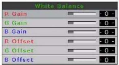
White Balance
The contrast and brightness for each color of the RGB Gain & Offset values in DLP can be individually adjusted.
Picture setting
This function stores Brightness, Contrast, Color, Tint, Sharpness, Gamma, Color Temp, Color Type, and White Enhance set in "Picture". Each stored setting is reassigned to each input mode.

Picture Setting
Normal
Select "Picture Setting" from the "Picture" menu on the menu screen.
→For operating the menu screen, see page 33.

Note
- When Recalling Saved Contents: When a saved memory number is selected, the contents of the "Picture" menu changes to the adjustment values of the saved memory number.
- When Editing Saved Contents: Edit the contents of the "Picture" menu after selecting the memory number for which adjustment values are to be edited.
Reset
Select this option to set to all items in the "Picture" menu to the factor y default values.
Adjusting Computer Images
(Computer Source Signal Only)
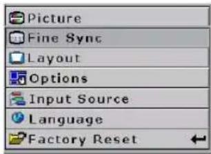
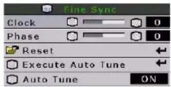
Use the Fine Sync function in case of irregularities such as vertical stripes or flickering in portions of the screen.
When Auto Tune is OFF
When "Auto Tune" is "OFF", interference such as flickering or vertical stripes may occur when displaying tiling or vertical stripes. Should this occur, adjust "Clock" and "Phase", to obtain an optimum image.
Select "Clock", "Phase", in the "Fine Sync" menu on the menu screen. For operating the menu screen, see page 33.
| Selected item Description | |
| Clock Adjusts vertical noise. | |
| Phase | Adjusts horizontal noise (similar to tracking on your VCR). |
Main Menu
Auto Tune adjustment
Automatically adjusts a computer image.
Select "Execute Auto Tune" from the "Fine Sync" menu on the menu screen.
For operating the menu screen, see page 33.
Screen display during Auto Tune
Auto Tune ...

Note
- Auto Tune may take some time to complete, depending on the image stored in the computer connected to the projector.
Easy to Use Functions
Selecting the Picture Display Mode
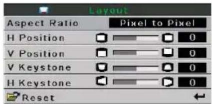
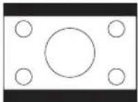
You can modify the picture display mode to enhance the input image. Depending on the input signal, you can choose "16:9", "4:3", "LBX" and "Native" image.
Switching the Picture Display using Different input signals
Press on the remote or

the projector and select a layout.
- Pressing Ⓗ cycles through the display modes

Info
- In the Pixel to Pixel Mode, images are displayed in the original resolution, and are not scalable.
Aspect Ratio
Aspect Ratio Function
You can control how the projector resizes the input image.
The following option are available:
16:9
• Resolution 1280 × 720
• 4:3 input is stretched to fit 16:9 display
- Stretches entire image.
Native
- Maintains input signal resolution. May have black borders around image.
4:3
• Resolution depends on the Input Signal
• 4:3 input scaled to fit display height
- Width scaled to maintain 4:3 aspect ratio
- Black bars on left and right (taking up 25% of the whole display)
LBX
• Resolution 1280 × 720
- 4:3 input scaled to fit display width
- Height scaled to maintain 4:3 aspect ratio: 1280 × 960
- 25% of the entire image on the top and bottom is cropped.
Main Menu
VIDEO
| 4:3 LBX 16:9 Native | |||||
| For 4:3 aspect ratio | 480i | 640X480i | |||
| 480P | 640X480P | ||||
| 576i | 768X576i | ||||
| 576P | 768X576 | 1280X720 | 1280X720 | 768X576P | |
| NTSC | 640X480 | ||||
| PAL | 768X576 | ||||
| SECAM | 768X576 | ||||
| For 16:9 aspect ratio | 480P | 768X576 | 1280X720 | 1280X720 | 720X480 |
| 576P | 768X576 | 1280X720 | 720X576 | ||
| 720P -- 1280x720 - | |||||
| 1080i -- 1280x720 - | |||||
| Input Signal | Output screen image | ||||
| 4:3 LBX 16:9 Native | |||||
| 480I480P576I576PNTSCPALSECAM | 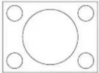 For 4:3 aspect ratio For 4:3 aspect ratio | *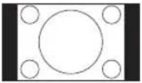 | 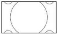 | 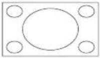 | 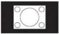 |
 Letter box image Letter box image | *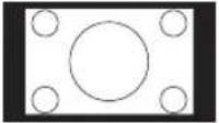 | 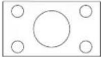 | 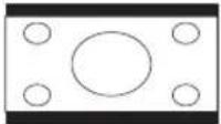 | 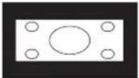 | |
| 1080I | 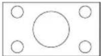 For 16:9 aspect ratio For 16:9 aspect ratio | 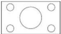 | |||
| 720P | 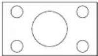 | 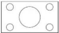 | |||
COMPUTER
| 4:3 | 16:9 | Native | ||
| For 4:3 aspect ratio | VGA(640X480) 960X720 1280X720 640X480 | |||
| SVGA(800X600) 960X720 1280X720 800X600 | ||||
| XGA(1024X768) 960X720 1280X720 1024X768 | ||||
| Input Signal | Output screen image | |||
| 4:3 | 16:9 | Native | ||
| VGA | 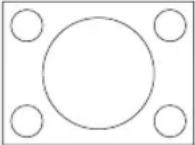 For 4:3 aspect ratio (640x480) For 4:3 aspect ratio (640x480) | 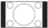 | 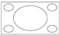 | 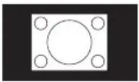 |
| SVGA | 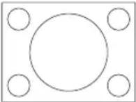 For 4:3 aspect ratio (800x600) For 4:3 aspect ratio (800x600) | 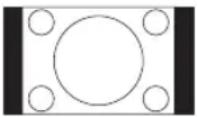 | 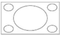 | 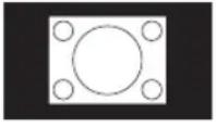 |
| XGA | 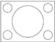 For 4:3 aspect ratio (1024x768) For 4:3 aspect ratio (1024x768) | 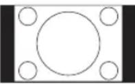 | 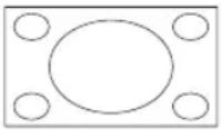 | 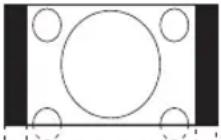 |
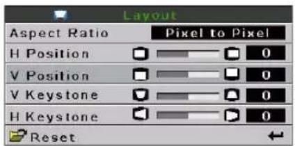
H-V Position Function
Use this to center the display vertically and horizontally.
1 In H Position, press “◀” or “▶”. The display moves left or right.
Main Menu
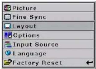
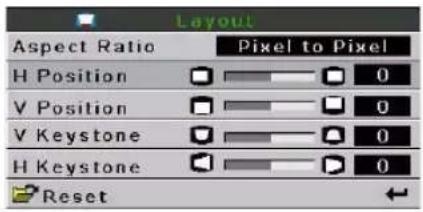
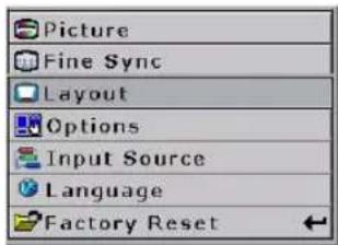
2 In V Position, press “◀” or “▶” The display moves upward or downward.
Main Menu
H-V Keystone Function
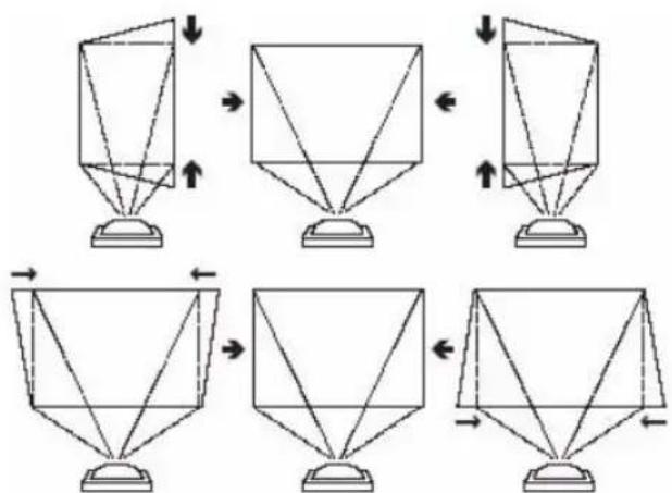
Correcting Trapezoidal Distortion and Adjusting Vertical Size.
This function allows for Keystone correction.

Note
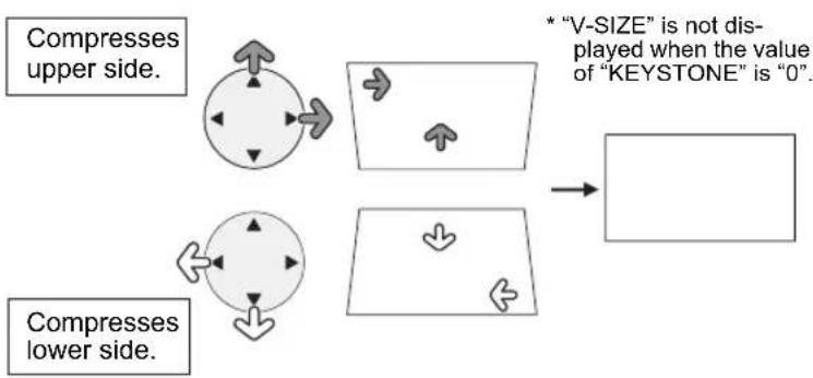
- When the image is projected at an angle, the image becomes distorted trapezoidally. The function for correcting trapezoidal distortion is called Keystone Correction.
(On-screen Trapezoidal Distortion)
Correction and the adjustment of the vertical size of the picture.
Main Menu
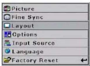
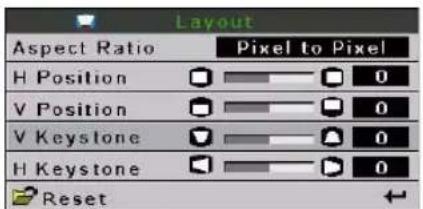
1 Select "V-Keystone" or "H-Keystone" in the layout.
| Selected item Description | |
| H Keystone | Horizontally adjusts the keystone settings. |
| V Keystone | Vertically adjusts the keystone settings. |
2 Press“◀” or “▶” to adjust the keystone correction.

Note
- Straight lines or the edges of images may appear jagged while adjusting the image.
flowchart
graph TD
    A["Compresses upper side."] --> B["Arrow pointing up"]
    C["Compresses lower side."] --> D["Arrow pointing down"]
    B --> E["Arrow pointing up"]
    D --> F["Arrow pointing down"]
    E --> G["Arrow pointing down"]
    F --> H["Arrow pointing down"]
    G --> I["Arrow pointing down"]
    H --> J["Arrow pointing down"]
    I --> K["Arrow pointing down"]
    style A fill:#f9f,stroke:#333
    style C fill:#f9f,stroke:#333
    style D fill:#f9f,stroke:#333
    style E fill:#ccf,stroke:#333
    style F fill:#ccf,stroke:#333
    style G fill:#cfc,stroke:#333
    style H fill:#cfc,stroke:#333
    style I fill:#fcc,stroke:#333
    note1["* 'V-SIZE' is not displayed when the value of "KEYSTONE" is "0"."]
Horizontal Keystone Correction
flowchart
graph TD
    A["Step 1: Top-angled pyramid structure"] --> B["Step 2: Top-angled pyramid structure"]
    B --> C["Step 3: Top-angled pyramid structure"]
    C --> D["Step 4: Top-angled pyramid structure"]
    D --> E["Step 5: Top-angled pyramid structure"]
    E --> F["Step 6: Top-angled pyramid structure"]
    F --> G["Step 7: Top-angled pyramid structure"]
    G --> H["Step 8: Top-angled pyramid structure"]
Vertical Keystone Correction
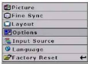
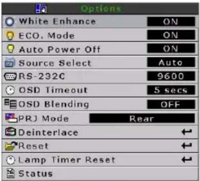
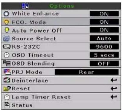
White Enhance
White enhance emphasizes the bright portions of images.
Main Menu
Selecting the Bright Mode
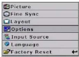
Bright mode reduces the power consumption of the projector.
Setting the Power Save
Select "ON" from the "Bright Mode" in the "Options" menu.
For operating the menu screen, see page 33.
Main Menu
Automatic Power Off Function
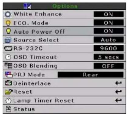
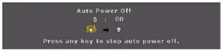
When set to "ON", the Auto Power Off switches the projector off if an input signal is not detected or you do not press any controls for 15 minutes.
Auto Power Off is disabled when set to "OFF".
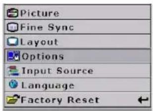
Select "Auto Power Off" from the "Options" menu on the menu screen. For operating the menu screen, see page 33.

Note
- When the Auto Power Off function is set to "ON", a warning, "Power OFF in 5 min." displays five minutes before the power turns off.
Main Menu
Source Select
This selects the input source automatically if no signal is detected on the current input.
Source Select
Auto Manual
Select "source select" from the "Options" menu on the menu screen. For operating the menu screen, see page 33.
Main Menu
OSD Timeout
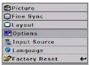
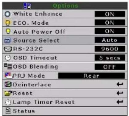
OSD Timeout is used to set how long the OSD stays open if no buttons are pressed.
| OSD Timeout | 51560 |
Main Menu
OSD Blending
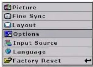
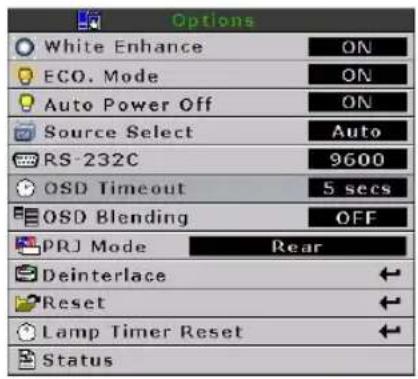
This allows you to set the transparency of the OSD menu. When set to transparent, you can see the image behind the menu.
Select "OSD Blending" from the "Options" menu on the menu screen. For operating the menu screen, see page 33.
| Selected item Description | |
| ON | OSD background will blend |
| OFF Normal | |
Main Menu
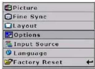
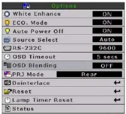
Reversing/Inverting Projected Images
The projector can reverse and invert images for various projection methods.
Setting the Projection Mode
Select "Projection Mode" from the "Options" menu on the menu screen. For operating the menu screen, see page 33.
| Selected item Description | |
| Front Normal image | |
| Ceiling + Front Inverted image | |
| Rear Reversed image | |
| Ceiling + Rear | Reversed and inverted image |
Main Menu
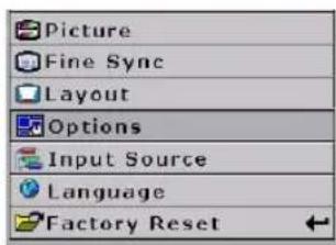
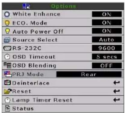

Note
- This function can be used for the reversed image and ceiling-mount setups.
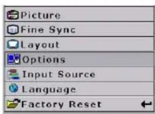
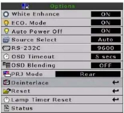
Deinterlace
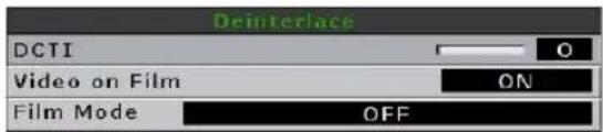
There are several different deinterlacing algorithms. Choose the setting that best matches the content you are watching.
Select "Deinterlace" from the "Options" menu on the menu screen. For operating the menu screen, see page 33.
| Selected item Description | |
| DCTI | Enhances video by replacing the edges of the video with edges that have steeper rise and fall times. DCTI turns sloped or sinusoidal waveforms into rectangular or square waveforms with the same duty cycles and peak-to-peak amplitude. It is useful for 4:1:1 video sources. The range is from 0 to 7. |
| Video on film (VOF) | Identifies video artifacts while in film mode. VOF attempts to repair the artifacts using the low-angle interpolator while remaining in film mode. |
| Film Mode | Reproduces the image of the film source clearly. Displays the optimized image of film transformed with 3:2 pull down (NTSC and PAL60Hz)or 2:2 pull down (PAL 50Hz and SECAM) enhancement to progressive mode images. |

Note
- In PAL50Hz or SECAM, the 2:2 pull down enhancement is enabled only in film mode, after the film source has been entered.
Main Menu
Reset
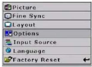
This resets all values in the "Option" menu to the factory defaults.
Main Menu
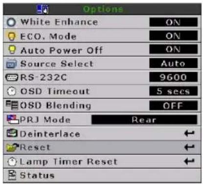
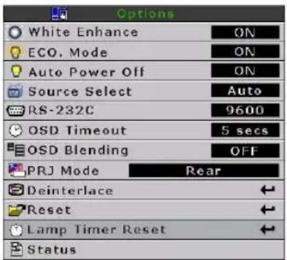
Lamp Timer Reset
The projector keeps a record of the total time the lamp has been in use. You should reset the timer after you install a new lamp. The total lamp usage time is shown in the Status Screen.
Main Menu
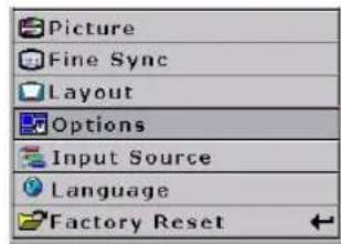
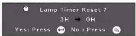
Status Screen
The Status screen displays information about the current input signal.
Main Menu
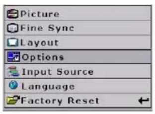
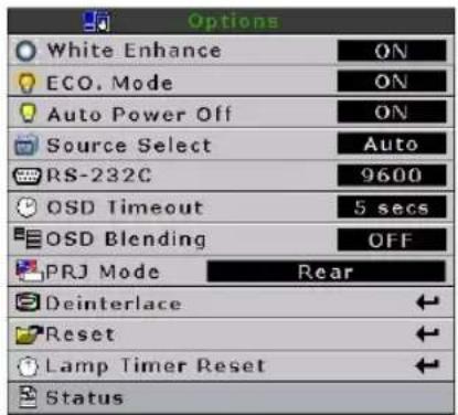
| S-Video : Component 1 |
| Resolution: 676x460 |
| Vert Freq: 60Hz |
| Horz Freq: 30KHz |
| CLamp Timer: 30H |
Factory reset
This resets all setting to the factory defaults. The logo is shown for about 20 seconds, then the projector is reset.
Main Menu
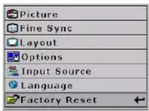
Factory Reset ...
Screen display during Factory Reset
NOTES
natural_image
Line drawing of a projector with ventilation slots and control buttons (no text or symbols)Appendix
Maintenance
Cleaning the projector
■ Unplug the power cord before cleaning the projector.
■ Avoid using benzene or thinner, as these can damage the finish on the cabinet and operation panel.
■ Do not use volatile agents, such as insecticides, on the projector.
■ Do not leave rubber or plastic objects in contact with the projector for long periods, as they may damage the finish of the projector.
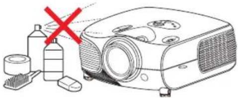
natural_image
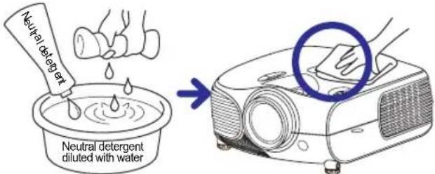
Illustration of a projector with a red X mark, accompanied by cleaning products including a brush, bottle, and filter (no text or symbols present)■ Wipe off dirt gently with a soft flannel cloth.
For hard-to-remove dirt, soak a cloth in a neutral detergent diluted with water, wring the cloth well and then wipe the projector.
Strong cleaning detergents may discolor, warp or damage the coating on the projector. Make sure to test on a small, inconspicuous area on the projector before using.
Cleaning the lens
■ Use a commercially available blower or lens cleaning paper (for glasses and camera lenses) for cleaning the lens. Do not use any liquid cleaning agents, as they may wear off the coating film on the surface of the lens.
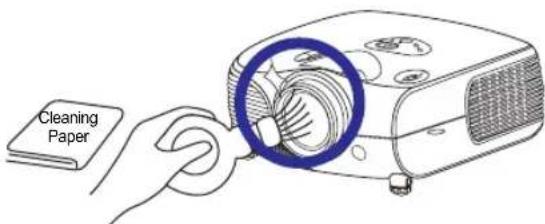
■ The surface of the lens is easily damaged, do not to scrape or hit the lens.
Cleaning the exhaust and intake vents
■ Use a vacuum cleaner to clean dust from the exhaust vent and the intake vent.
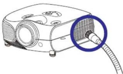
natural_image
Line drawing of a projector with a cable inserted, showing internal components and a magnified inset (no text or symbols)Cleaning the Ventilative Holes
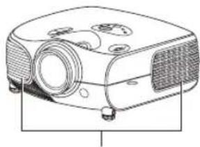
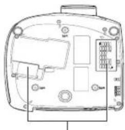
- This projector has ventilative holes to ensure the optimal operating condition of the projector.
• Periodically clean the ventilative hole by vacuuming it off with a vacuum cleaner. - The ventilative holes should be cleaned every 100 hours of use. Clean the ventilative holes more often when the projector is used in dirty or smoky locations.
Side and Rear view
natural_image
Line drawing of a projector with lens and control panel (no text or symbols)Ventilative holes
Bottom view
natural_image
Technical line drawing of a device rear panel with buttons and ports (no text or symbols)Ventilative holes
Cleaning the Ventilative Holes
1 Turn off the power and disconnect the power cord.
Press on the projector or on the remote control to turn off the power. Wait until the cooling fan stops.
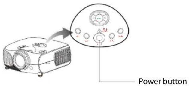
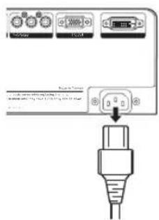
2 Unplug the Power Cord.
3 Clean the dust off by placing the cleaner hose on the intake and exhaust ventilative holes.
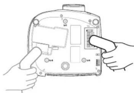
natural_image
Line drawing of hands installing or adjusting a device panel with buttons and ports (no text or symbols)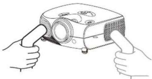
natural_image
Line drawing of two hands inserting a projector into a housing (no text or symbols)About the Lamp
The projector lamp has a life of 2000 hours. Maintain proper ventilation to keep the lamp operating throughout its lifetime. Do not subject the projector to unnecessary vibration to ensure that the lamp does not break.
It is recommended that the lamp (sold separately) be replaced after approximately 2,000 cumulative hours of use or when you notice a significant deterioration in the picture and color quality. The number of hours the lamp has been used can be checked with "Lamp Timer" in the "Options" menu on the menu screen.
■ For lamp replacement, please consult your nearest authorized service center or sealer.
■ The actual lamp service life may be less than 2000 hours depending on the environment in which the projector is used.
Caution Concerning the Lamp
This projector uses a pressurized mercury lamp. A loud sound may indicate lamp failure. Lamp failure is caused by excessive shock, improper cooling, surface scratches or deterioration of the lamp due to usage. The period of time up to failure largely varies depending on the individual lamp and/or the condition and the frequency of use. It is important to note that failure can often result in the bulb cracking.
■ When the lamp replacement indicator and on-screen display icon are illuminated or are flashing, it is recommended that the lamp be replaced immediately, even if the lamp appears to be operating normally.
If the lamp breaks glass particles may spread inside the lamp cage or gas contained in the lamp may be vented into the room from the exhaust vent. As the gas in this lamp contains mercury, ventilate the room well if the lamp breaks and avoid all exposure to the released gas. In case of exposure to the gas, consult a doctor as soon as possible.
If the lamp breaks, there is also a possibility that glass particles may spread inside the projector. If this happens, it is recommended you contact your nearest authorized dealer to remove the damaged lamp and assure safe operation.
Replacing the Lamp
CAUTION! Do not remove the lamp unit immediately after operation of the projector. The lamp will be hot and touching it may cause injury. Wait at least one hour after the power cord is disconnected to allow the surface of the lamp unit to fully cool before removing the lamp unit.
Temperature LED (Over Temperature)
The over temperature alarm LED on the control panel alerts you when the projector lamp becomes too hot.
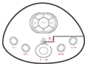
Over Temperature Alarm LED
If the LED illuminates during operation, the lamp will shut off and the cooling fans will continue to run for approximately two minutes. You should ensure that the airflow around the projector is sufficient, and that the aire filters are not clogged to ensure that the projector has proer ventilation.
Over Temperature!
When the temperature LED lights up, a warning also appears on the screen.
Removing and Installing the Lamp Unit
Follow these instructions to replace the lamp.
- Remove the lamp unit by the handle. Do not to touch the glass surface of the lamp unit or the inside of the projector.
• To avoid injuring yourself and damage to the lamp, carefully follow the steps below. -
Do not loosen other screws except for the lamp unit cover and lamp unit.
(Only the silver screws are loosened). -
If the projector is running, press ⏻ on the projector or ⏻ on the remote control to turn off the power. Wait until the cooling fan stops.
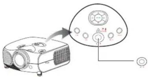
Warning!
Do not remove the lamp unit from the projector imme diately after use. The lamp will be very hot and may cause injury.
-
Disconnect the power cord and wait at least an hour for the lamp to cool.
-
Remove the lamp unit cover.
- Loosen the user service screw that secures the lamp uni t cover. Then open the cover in the direction of the arrow.
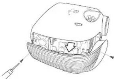
natural_image
Technical line drawing of a mechanical device with internal components and directional arrows (no text or symbols)M4* 8.9 screws
4. Remove the lamp unit.
- Loosen the securing screws from the lamp unit. Hold the lamp unit by the handle and pull it in the direction of the arrow.
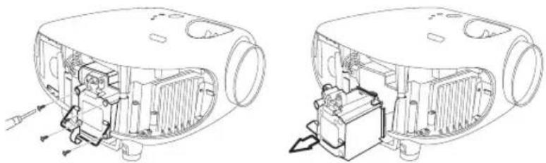
natural_image
Technical line drawings of a vehicle's internal components, showing exploded and assembled views (no text or symbols)5. Insert the new lamp unit.
- Press the lamp unit firmly into the lamp unit compartment. Fasten the securing screws.
- Attach the lamp unit cover.
- Close the lamp unit cover in the direction of the arrow (to the close mark) on the side of the projector.
- Tighten the user service screw.
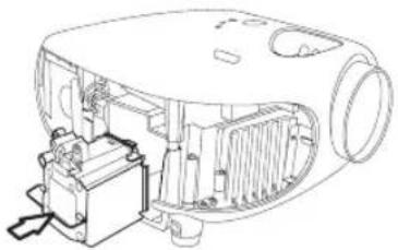
natural_image
Technical line drawing of an electronic device with internal components (no text or symbols)
Info
- If the lamp unit and lamp cover are not correctly installed, the power will not turn on, even if the power cord is connected to the projector.
Resetting the Lamp Timer
Reset the lamp timer after replacing the lamp.
1. Connect the power cord.
- Plug the power cord into the AC socket of the projector.
2. Reset the lamp timer.
- While holding down and on the projector, press on the projector. (See page 50)
- "LAMP 0H" is displayed, indicating that the lamp timer is reset.

Info
Make sure to reset the lamp timer only when replacing the lamp. If you reset the lamp timer and continue to use the same lamp, this may cause the lamp to become damaged or explode.
Connecting Pin Assignments
DVI-D port: 25 pin connector
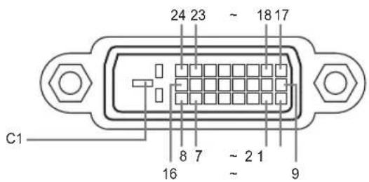
• DVI Digital INPUT
Pin No.Signal Pin No.Signal
1 T.M.D.S data 2-16 Hot plug detection
2 T.M.D.S data 2+ 17 T.M.D.S data 0-
3 T.M.D.S data 2 shield 18 T.M.D.S data 0+
4 Not connected 19 T.M.D.S data 0 shield
5 Not connected 20 Not connected
6 DDC clock 21 Not connected
7 DDC data 22 T.M.D.S clock shield
8 Not connected 23 T.M.D.S clock+
9 T.M.D.S data 1–24 T.M.D.S clock-
10 T.M.D.S data 1+ C1 Ground
11 T.M.D.S data 1 shield
12 Not connected
13 Not connected
14 +5V power from graphic card.
15 Ground
RS-232C Port: 9-pin D-sub Female connector of the DIN-D-sub RS-232Cvt cable pin connector
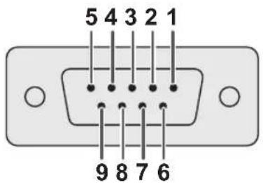
| Pin No. | Signal | Name | I/O | Reference |
| 1 | Not connected | |||
| 2 | SD | Send Data | Input | Connected to internal circuit |
| 3 | RD | Receive Data | Output | Connected to internal circuit |
| 4 | Not connected | |||
| 5 | SG | Signal Ground | Connected to internal circuit | |
| 6 | Not connected | |||
| 7 | Not connected | |||
| 8 | Not connected | |||
| 9 | Not connected |
Computer Compatibility Chart
Computer
- Multiple signal support
Horizontal Frequency: 25–75 kHz, Vertical Frequency: 50–85 Hz, Pixel Clock: 25–108 MHz - Compatible with sync on green and composite sync signals
• XGA compatible with advanced intelligent compression
The following is a list of modes that conform to VESA. However, this projector supports other signals that are not VESA standards.
| PC/MAC/WS | Resolution | Horizontal Frequency (kHz) | Vertical Frequency (kHz) | VESA Standard | DVI Support | |
| PC VGA | 640 x 350 | 31.5 70 | ||||
| 640 x 480 | 31.5 60 | √ | ||||
| 37.9 72 | √ | |||||
| 37.5 75 | √ | |||||
| 43.3 85 | √ | |||||
| Resolution | Horizontal Frequency (kHz) | Vertical Frequency (kHz) | VESA Standard | DVI Support | Display | |
| DVI | 720 × 480 | 31.5 60 | √ | Upscale | ||
| 720 × 576 | 31.3 50 | |||||
| 1280 × 720 | 45 60 | |||||
| 37.5 50 | ||||||
| 1980 × 1080i | 33.8 60 | |||||
| 28.1 50 | ||||||
| PC/MAC/WS | Resolution | Horizontal Frequency (kHz) | Vertical Frequency (kHz) | VESA Standard | DVI Support | |
| PC | SVGA | 800 x 600 | 35.1 56 | √ | √ | |
| 37.9 60 | ||||||
| 48.1 72 | ||||||
| 46.9 75 | ||||||
| XGA | 1024 x 768 | 48.4 60 | √ | √ | ||
| 56.5 70 | ||||||
| 60.0 75 | ||||||
| 68.7 85 | ||||||
| MAC 13" | VGA | 640 x 480 34.9 | 67 | |||
| MAC 16" | SVGA | 832 x 624 49.6 | 75 | |||
| MAC 19" | XGA | 1024 x 768 48.4 | 60 | √ | ||

Note
- This projector may not be able to display images from notebook computers in simultaneous (CRT/LCD) mode. Should this occur, turn off the LCD display on the notebook computer and output the display data in "CRT only" mode. Details on how to change display modes can be found in your notebook computer's operation manual.
- When this projector receives 640 × 350 VESA format VGA signals, "640 × 400" appears on the screen.
- When projecting video images of an interlace video signal with the projector, the intended image may not be projected depending on the video signal when using the RBG input. In such cases, use the component input, S-video input or video input.
Video Compatibility Chart
| Resolution | H-Freq (kHz) | V-Freq (Hz) | Comp1 Support | Comp2 Support | S-Video Support | Compos- ite Support | VGA Support | DVI Support | |||
| SD Video NTSC 640x480i 15.73 59.94/60 | ✓ | ✓ | ✓ | ✓ | |||||||
| PAL 768x576i 15.63 50 | ✓ | ✓ | ✓ | ✓ | |||||||
| SECAM 768x576i 15.63 50 | ✓ | ✓ | ✓ | ✓ | |||||||
| NTSC-4.43 △ | △ | △ | |||||||||
| PAL-M △ | △ | △ | |||||||||
| PAL-N △ | △ | △ | |||||||||
| NTSC-J △ | △ | △ | |||||||||
| PAL-60 △ | △ | △ | |||||||||
| NTSC-50 | |||||||||||
| ED TV | 480P 720x480P | 31.5 | 59.94/60 | ✓ | ✓ | ✓ | ✓ | ||||
| 576P 720x576P | 31.3 | 50 | ✓ | ✓ | ✓ | ✓ | |||||
| HD TV 1080i/50 | 1920x1080i | 33.8 | 50 | ✓ | ✓ | ✓ | ✓ | ||||
| 1080i/60 | 1920x1080i | 28.1 | 59.94/60 | ✓ | ✓ | ✓ | ✓ | ||||
| 720P/50 | 1280x720P | 37.5 | 50 | ✓ | ✓ | ✓ | ✓ | ||||
| 720P/60 | 1280x720P | 45.0 | 59.94/60 | ✓ | ✓ | ✓ | ✓ | ||||
| HTPC | 720P/48 | 1280x720P | 48 | ||||||||
| 720P/75 | 1280x720P | 75 | |||||||||
- Component 1/2 support signal formats are Y/Pb/Pr, Y/Cb/Cr
- VGA port support signal formats are RGsyncB, RGBHV or RGBCsysc
- “△” means manual setting is needed
DTV
| Signal | Horizontal Frequency (kHz) | Vertical Frequency (Hz) | DVI Support |
| 480P | 31.5 | 60 | √ |
| 576P | 31.3 | 50 | √ |
| 720P | 45.0 | 60 | √ |
| 720P | 37.5 | 50 | √ |
| 1080I | 33.8 | 60 | √ |
| 1080I | 28.1 | 50 | √ |
IR Remote Key Discrete Codes
| Key | Code | Key | Code |
| IR POWER | 0x00 | IR_Aspect | 0x0c |
| IR MENU | 0x01 | IR_PowerOff | 0x0d |
| IR UP | 0x02 | IR_Standard | 0x0e |
| IR DOWN | 0x03 | IR_Letterbox | 0x0f |
| IR LEFT | 0x04 | IR_Anamorphic | 0x10 |
| IR RIGHT | 0x05 | IR_PixelToPixel | 0x11 |
| IR ENTER | 0x06 | IR_S_Video | 0x12 |
| IR_Exit | 0x07 | IR_Composite 0x13 | |
| IR_Source1 | 0x08 | IR_Component1 | 0x14 |
| IR_Source2 | 0x09 | IR_Component2 | 0x15 |
| IR_Source3 | 0x0a | IR_DVI | 0x16 |
| IR_Source4 | 0x0b | IR_PC | 0x17 |
Troubleshooting
| Problem Check | |
 Projector does not start Projector does not start | Projector power cord is not plugged into the wall outlet. |
| Remote control batteries have run out. | |
 No picture No picture | The selected input mode is wrong. |
| Cables may be incorrectly connected to the rear panel of the projector. | |
| Power to the external connected device is off. | |
| The video signal format of the video equipment is not set correctly. | |
 Color is faded Color is faded | Picture adjustments are incorrectly set. |
 Picture is blurred Picture is blurred | Focus is incorrectly set. |
| The projection distance exceeds the focus range. | |
 Picture noise appears. Picture noise appears. | (PC input only) |
| Try "Auto tune". | |
| Adjust the "Clock" setting. | |
| Adjust the "Phase" setting. | |
 Picture is green on INPUT1 or 2 COMPONENT Picture is green on INPUT1 or 2 COMPONENT | Change the input signal type of the video equipment. |
natural_image
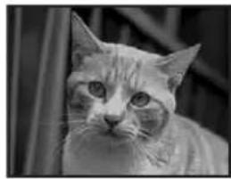
Black-and-white photo of a cat with large eyes and striped fur, partially obscured by foliage (no text or symbols visible)Picture is dark or bright and whitish
Picture adjustments are incorrectly set.
natural_image
Close-up of a cat's face with large eyes and fluffy ears (no text or symbols visible)Picture is too bright and whitish
Picture adjustments are incorrectly set.
natural_image
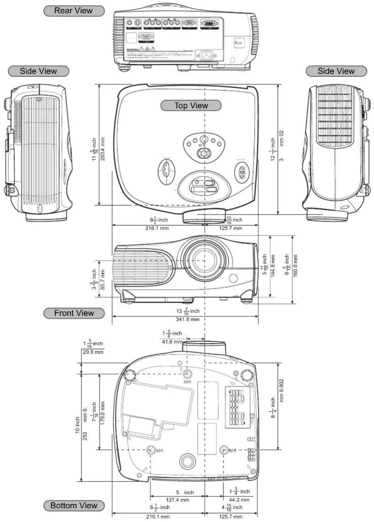
Black-and-white photo of a cat with large eyes and striped fur, partially obscured by foliage (no text or symbols visible)Dimensions
Units: inches (mm)
- Safety Information
- Class B emissions limits
- Important Safety Instruction
- Do:
- Don't:
- Eye Safety Warnings
- Contents
- Introduction
- Connections and Setup
- Basic Operation
- Easy to Use Functions
- Appendix
- Package Contents
- Strandard Accessories
- Optional Accessories
- Note
- Features
- Components
- Projector (Front and Top View)
- Temperature indicator
- Projector (Rear View)
- Using the Remote Control
- Available Range of the Remote Control
- Inserting the Batteries
- Connecting the Projector to Other Devices
- Before Setting Up
- This projector can be connected to
- Connecting the Power Cord
- Connecting to Video Equipment
- Notes
- Connecting to Component Video Equipment
- Connecting Using the DVI Cable
- Optional accessory
- Connecting Using a DVI-D to HDMI Cable
- Connect a DVI-D to HDMI cable to the projector.
- Connect the above cable to the video equipment.
- Connecting the Projector to a Computer
- Connect the projector to the computer using an HD 15-pin VGA cable.
- Connecting the Cables
- "Plug and Play" Function
- Using the Adjustment Feet
- Info
- Adjusting the Lens
- Using the Lens Shift
- Setting up the Screen
- Standard Setup (Front Projection)
- An Example of Standard Setup
- 2D Lens Shift:
- Screen Size and Projection Distance
- Projection from behind the screen
- Projecting a Reversed/Inverted Image
- Projection using a mirror
- Ceiling-mount setup
- Image Projection
- Basic Procedure
- Plug the power cord into the wall outlet.
- Press on the remote control or on the projector.
- Press on the projector to
- Press on the remote control
- Selecting the On-screen Display Language
- Menu Bar Items
- Using the Menu Screen
- MenuSelections (Adjustments)
- Adjusting the Image
- Brightness
- Contrast
- Color
- Tint
- Sharpness
- Color TEMP
- Gamma
- White Balance
- Picture setting
- Reset
- Adjusting Computer Images
- When Auto Tune is OFF
- Auto Tune adjustment
- Selecting the Picture Display Mode
- Aspect Ratio Function
- 16:9
- Native
- 4:3
- LBX
- VIDEO
- COMPUTER
- H-V Position Function
- H-V Keystone Function
- Correcting Trapezoidal Distortion and Adjusting Vertical Size.
- Select "V-Keystone" or "H-Keystone" in the layout.
- Press“◀” or “▶” to adjust the keystone correction.
- White Enhance
- Selecting the Bright Mode
- Setting the Power Save
- Automatic Power Off Function
- Source Select
- OSD Timeout
- OSD Blending
- Reversing/Inverting Projected Images
- Setting the Projection Mode
- Deinterlace
- Lamp Timer Reset
- Status Screen
- Factory reset
- Maintenance
- Cleaning the projector
- Cleaning the lens
- Cleaning the exhaust and intake vents
- Cleaning the Ventilative Holes
- About the Lamp
- Caution Concerning the Lamp
- Replacing the Lamp
- Temperature LED (Over Temperature)
- Removing and Installing the Lamp Unit
- Warning!
- Remove the lamp unit.
- Insert the new lamp unit.
- Resetting the Lamp Timer
- Connect the power cord.
- Reset the lamp timer.
- Connecting Pin Assignments
- • DVI Digital INPUT
- Pin No.Signal Pin No.Signal
- Computer Compatibility Chart
- Video Compatibility Chart
- Troubleshooting
- Dimensions
Brand : OPTOMA
Model : HD7100
Category : Video projector