
FSG54S - Oven Euromaid - Free user manual and instructions
Find the device manual for free FSG54S Euromaid in PDF.


| Product Type | Freestanding Oven |
| Brand | Euromaid |
| Model | FSG54S |
| Fuel Type | Gas (Natural or LPG) |
| Dimensions (H x W x D) | 900 x 600 x 600 mm |
| Weight | 55 kg |
| Oven Capacity | 115 liters |
| Functions | Bake, Grill, Fan Forced, Defrost |
| Temperature Control | Thermostat (50-260°C) |
| Safety Features | Flame failure safety device, Child lock |
| Cleaning | Manual cleaning required |
| Interior Light | Yes, replaceable bulb |
| Finish | Stainless steel |
| Energy Efficiency | Class A |
| Spare Parts Availability | Available from Euromaid |
Frequently Asked Questions - FSG54S Euromaid
User questions about FSG54S Euromaid
0 question about this device. Answer the ones you know or ask your own.
Ask a new question about this device
Download the instructions for your Oven in PDF format for free! Find your manual FSG54S - Euromaid and take your electronic device back in hand. On this page are published all the documents necessary for the use of your device. FSG54S by Euromaid.
USER MANUAL FSG54S Euromaid
540mm Upright Gas Cooker FGO54W, GG54GOW, FGO54S, FSG54S, GG54GOS
contents
Conditions of use ....3
Safety precautions....3
Other important safety information....4
Warnings for use of grill, oven, and appliance hob 4
Disposal of packaging....4
Installation, cleaning and servicing....4
Product description....5
Controls....5
First time use the appliance ....6
Oven shelf location....6
Using the oven 7
Using the oven of our gas cooker ....7
Set the cooking time ....7
Oven cooking guide ....8
Understanding baking problems....9
Using the grill....10
Handling Grilling problems ....10
Using the hotplates of your cooker....11
Fitting oven accessories and cleaning 12
Cleaning the upright cooker....12
Cleaning the oven door 13
Replacing the lamp....14
Solving problems....15
Installing cooker - power connections .....16
Installing anti tilt plate....17
Installing your gas cooker....18
Safety warning about installation ....20
Testing the operation of the gas cooker....21
Technical specifications ....22
We recommend that you read the instructions in this Manual carefully before use for the best performance and to extend the life of your appliance, as it will provide you with all the instructions you require to ensure its safe installation, use and maintenance. Always keep this Manual close to hand since you may need to refer to it in the future. Thank you.
Conditions Of Use
This appliance is intended to be used for domestic use, not commercial use.
Safety Precautions
- This appliance is not intended for use by persons (including children) with reduced physical, sensory or mental capabilities, or lack of experience and knowledge, unless they have been given supervision or instruction concerning use of the appliance by a person responsible for their safety.
- Warning – ensure that no downward pressure is applied to the oven door when open. in particular, do not allow a child to climb on to open oven door.
- Warning - accessible parts can become hot during use, especially the oven door. to avoid burns, young children must be kept away.
● Young children should be supervised to ensure they do not play with this appliance. - During use this appliance becomes hot. Care should be taken to avoid touching hot external and internal surfaces when in use. Use oven gloves.
● Install cooker, shelving and fittings in accordance with this Manual. - Ensure all specified vents, openings and airspaces are not blocked.
- To ensure your safety all electric appliance should only be installed or service by qualified staff. If the supply cord is damaged, it must be replaced a service agent or similarly qualified person in order to avoid a hazard.
- To ensure your safety all electric appliance should only be installed or service by qualified staff. If the supply cord is damaged, it must be replaced by the manufacture, its service agent or similarly qualified staff in order to avoid a hazard.
- Do not spray aerosols in the vicinity of this appliance while it is in operation.
- Do not store flammable materials in the appliance or near this appliance.
- Do not operate the gas appliance if the smell of gas persists.
- Do not modify this appliance.
- Appliance must be installed according to current laws and regulations by qualified / authorised tradesmen / installers
The Manufacturers and Importers/Distributors and Retailers shall not be liable to any legal liability, personal injury and property damage due to incorrect operation or incorrect Installation.
Other Important Safety Information

This appliance must not be used as a space heater

Do not obstruct the ventilation slots on front or back of appliance.

Do not remove rating or warning labels or use abrasive/ corrosive cleaners on surfaces

According to the electrical safety regulations the appliance equipment must be properly earthed.

Do not use corrosive cleaners eg oven cleaners that contain caustic soda.
Warnings for use of grill, oven, and appliance hob
Grill warnings
- Do not leave grill on unattended.
- Do not cover the grill dish insert with foil.
- Placing thick portions of food under grill can be a fire hazard.
- Fat left on a grill dish is a fire hazard! Keep grill clean and turn off grill immediately after use.
Oven warnings
- Do not push down or apply any weight on open oven door.
- Do not line oven with foil or place anything on the bottom of the oven while baking to avoid permanent damage, as trapped heat will crack or craze the enamel floor of the oven cavity liner.
- Use of olive oil and other poly-unsaturated oils (vegetable oils) when roasting uncovered food causes deposits inside the oven which are very difficult to remove.
NOTE: Condensation on oven door is normal, especially when kitchen is cold
Also spacing and size of food on trays and the number of baking dishes in the oven can affect air circulation.
Disposal of packaging
Please recycle the cardboard, and also any polystyrene packaging where possible.
Installation, Cleaning and Servicing
● An authorized person must install this appliance. (Certificate of Compliance to be retained).
● Before using the appliance, ensure that all packing materials are removed from the appliance.
- In order to avoid any potential hazard, the Installation Instructions must be followed.
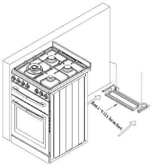
- In order to avoid accidental tipping of the appliance (for example, by a child climbing onto the open oven door), the anti tilt plate must be installed.
- Where the appliance is installed next to cabinets, the cabinet material must be capable of withstanding 85°C.
- Only authorized personnel should carry out servicing (Certificate of Compliance to be retained).
● Always ensure the appliance is switched off before cleaning.
- Do not use caustic soda- based cleaners.
- Do not use steam cleaners, as this may cause moisture build up.
● Always clean the appliance immediately after any food spillage.
- To be serviced only by an authorized person.
● Appliances requiring connection to 220-240V and must be earthed.
Gas models are NOT APPROVED for installation in marine craft, caravans or mobile homes.
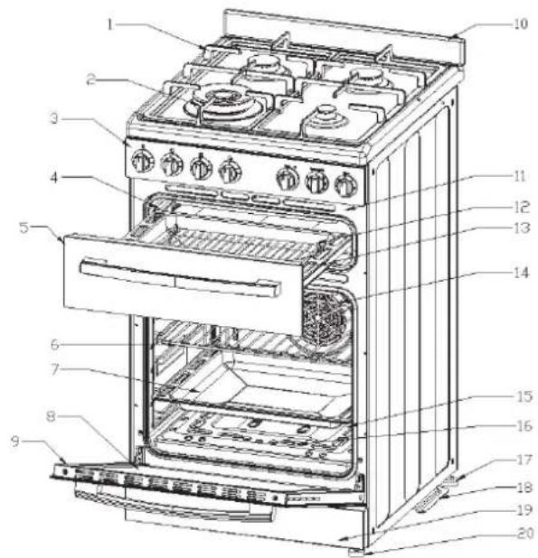
Product description
Description of gas cooker
- Cast iron pan support (trivet) includes WOK trivet (not pictured)
- Hotplate Burner with removable cap, distributor x 4
- Control Panel
- Telescopic runner
- Grill Drawer
- Shelf
7 - 13. Grill / Oven tray (1 only supplied) - Oven Door Glass
- Oven Door
- Splashback (1 supplied)
- Grill hidden Oven Element
- Rack in grill tray (1 supplied)
- Fan
- Oven burner cover plate
- Oven burner
- Anti slip feet
- Anti tilt bracket
- Kick panel
- Anti slip feet
Description of front panel
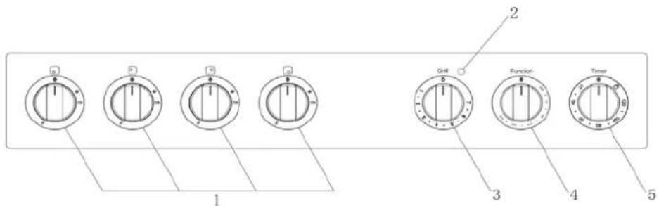
Controls
- Hotplate Burner Control Knob
☐ Sets the hotplate cooking temperature.
- Grill Indicator Lamp
□ Comes on when grilling.
- Grill Temperature Control Knob
□ Adjusts grilling temperature.
- The burner control knob
☐ Sets Oven temperature.
- 120 Minute Minute Minder Timer
Sets "reminder" alarm count-down time that will have an audible sound when cooking time reached.
Note: The oven burner control knob has to be held down first.
First time use the appliance
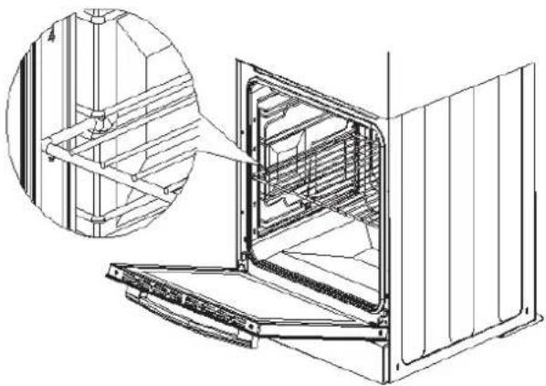
Fitting oven shelves
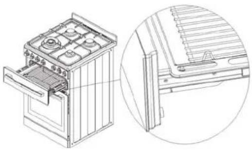
- Ensure shelf orientation is correct (refer picture).
- Slide into oven at an angle until raised back of shelf is past the stop on side runners.
● Lower front of shelf and push in until stop is reached.
NOTE: The topledge is not a shelf position
natural_image
Technical line drawing of an open refrigerator with a close-up inset showing internal structure (no text or symbols)Preparing your appliance for the first time
- Please wipe out the oven interior prior to operation with warm soapy water and polish dry with a soft clean cloth.
- New appliances can have an odour during first operation. It is recommended to 'run in' your oven before you cook for the first time. Run the oven at 180°C for 2-4 hours and ensure that the room is well ventilated.
- Please install oven furniture as outlined in the "Fitting Oven Accessories and Cleaning" section.
- The electric grill may have oils left on the grill during manufacture. Before you cook on the grill for the first time, turn on for 15 minutes with 10mm of water in the bottom of the grill dish.
Oven shelf location (5 positions rack)
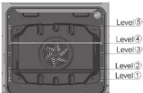
Shelf position is counted from the bottom shelf up. Bottom shelf position is 1.
Using the oven
Oven safety warnings
● Always follow the instructions for putting the shelves and side racks into the oven, to avoid accidents.
- Do not line the oven with foil, it will damage the enamel.
- Do not touch the hot surfaces or heating elements inside the oven.
- Do not use the oven door as a shelf.
- Do not push down on the open oven door.
- Do not place shelves on top of upper most shelf runner as there are no stops for shelf withdrawal.
● After each use, always check that the control knobs are turned to 0(off).
Using the oven of your gas cooker
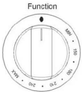
Set 1) Temperature
2) Cooking time
3) Gas Oven Function
This knob lights the gas burner inside the oven. The cooking temperature is set by turning the knob anti-clockwise to the value required, between Min. and Max.
2) Set cooking time
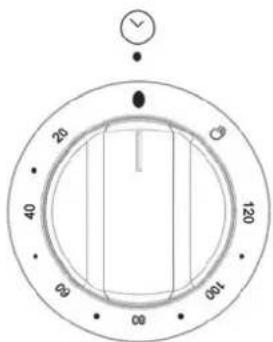
120 Minute Ringer Timer
- To set the timer, simply turn the knob clockwise to the required number of minutes.
- Turn knob counterclockwise to use 🏠 "the oven with no cooking time control
Note: For any time below fifteen minutes turn the knob past the fifteen then turn it back to the required number of minutes. When the timer returns to zero,
the timer gives a short ring.
Using the gas oven
Electronic spark ignition
Completely open the oven door and press the thermostat knob while turning it anti-clockwise to the maximum temperature setting; this automatically activates the electric spark ignition device. Once the burner has ignited, keep the knob pressed down for a few seconds to allow the thermocouple to heat up.
If the burner has not lit after 15 seconds, stop trying, leave the oven door open and wait 1 minute before trying again.
Lighting the burner by hand
Completely open the oven door and turn the thermostat knob
Anti-clockwise. Place a lit match close to the end of the flame pipe A in the centre of the bottom of the oven and press the thermostat knob. Once the burner has ignited, keep the knob pressed down for a few seconds to allow the thermocouple to heat up and check that the burner has lit properly
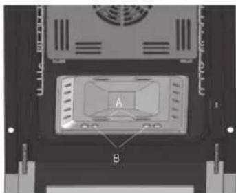
through the inspection hole B. The cooking temperature is set by turning the knob clockwise to the value required, between 50° and 231°. If the burner accidentally goes out, turn the knob to the off ( ) position and wait at least one minute before trying to relight it.
Oven cooking guide
The following is intended as a rough guide. It is often required to set oven 10-20 degrees above or below this guide to get the result you want. Also adjustments are needed for the cooking time to suit personal expectations,
Where the gas models vary from electric, details for gas cooking is shown in brackets. For best results when baking, preheat your oven for 15-20 minutes.
| Food | Fan forced oven | Time in minutes | |
| Temperature (°C) | Oven shelfposition | ||
| Plain or fruit scones 210 Any 10-15 | |||
| Rolled biscuits 150(170) Any 10-15 | |||
| Spooned biscuits 180 Any 12-15 | |||
| Shortbread biscuits 150 Any 30-35 | |||
| Hard individual meringues 100 Any 90 | |||
| Soft individual meringues 165 Any 15-20 | |||
| Pavlova | 100 | Any | 75 |
| Patty cakes | 180 Any 15-20 | ||
| Sponge | 170 Any 20-30 | ||
| Plain butter cake | 170 Any 25-40 | ||
| Rich fruit cake | 130 Any 180 | ||
| Shortcrust cornish pasty | 160(180) | Any | 40-45(10/35) |
| Shortcrust custard tart | 170-200 | Any | 20-30(10/25) |
| Cream puffs | 200 Any 25-30 | ||
| Yeast bread | 200 Any 25-30 | ||
| Pizza | 220 Any 15-25 | ||
| Meat/Poultry/Fish | Recommended temperature (°C) | Minutes per kilogram | |
| Beef | Rare | 200 | 35-40 |
| Medium | 200 | 45-50 | |
| Well done | 200 | 55-60 | |
| Lamb | Medium | 200 | 40 |
| Well done | 60 | ||
| Veal | 180 | 60 | |
| Pork | 200 | 60 | |
| Chicken | 180-200 | 45-60 | |
| Duck | 180-200 | 60-70 | |
| Turkey | 180 | 40-45 (less than 10kg) | |
| 35-40 (more than 10kg) | |||
| Fish | 180 | 20 | |
Understanding baking problems
| Problem Causes What to do | ||
| Uneven cooking | Incorrect shelf position Select shelf that puts food in centre of oven | |
| Oven tray too large Remove oven tray. Use smaller trays or dishes | ||
| Trays not in centre Put trays in centre | ||
| Oven fan causing uneven browning or small cakes to lean over | Rotate food during cooking, or use Conventional Mode (i.e. no fan) | |
| Baked products too brown on top | Oven not preheated Preheat the oven | |
| Baking tins too large (diameter) for recipe | Use correct size tins | |
| Fan-forced mode with oven temperature too high | Check recipe. Reduce oven temperature by 10 - 20 or more | |
| Cooking time too long Next time, shorten cooking time | ||
| Baking tins not evenly spaced Stagger baking | tins at least 3cm between tins and the oven walls | |
| Items to be cooked are not evenly sized or spaced on trays | Make into same size and shape and spread evenly over trays | |
| Baked products too brown on bottom | Baking tins too large (diameter) Use correct size tins | |
| Baking tins are dark metal or glass | Change to shiny, light tins or lower the temperature by 10^ -20 C | |
| Food too low in oven | Cook one shelf higher | |
| Oven door opened too frequently during baking | Don't open the oven door until at least half the cooking time has passed | |
| Baking temperature too high | Lower the temperature | |
| Oven tray blocking heat (below thermostat) | Use higher shelf position for oven tray | |
| Cakes have a cracked thick crust | Baking temperature too high | Lower the temperature |
| Food too low in oven | Cook one shelf higher | |
| Cake batter over mixed | Mix just long enough to combine the ingredients | |
| Baking tin too deep | Check size of tin and use recommended size | |
| Baking tins dark | Change to shiny light tins | |
| Baked products are pale, flat and undercooked | Baking temperature too low | Raise the temperature |
| Food too low in oven | Cook one shelf higher | |
| Baking time too short | Increase cooking time | |
| Incorrect baking tin size | Use correct size tin | |
| Cakes fallen in centre | Baking temperature too low | Raise the temperature |
| Baking time too short | Increase cooking time | |
| Proportions of ingredients incorrect for recipe | Check recipe | |
| Opening door too early during baking | Do not open door until the last quarter of cooking time | |
| Roast meat and potatoes not browning in fan oven | Poor hot air circulation | Elevate food onto a rack to allow air circulation |
| Oven temperature is too low | Increase temperature to 200 - 220 | |
| Not long enough in oven | Continue cooking for another 15+ minutes | |
Using the grill
Grill safety warnings
● Always turn off the grill immediately after you have finished cooking and pull drawer out or remove grill tray otherwise fat left in the tray in the hot grill compartment will continue to smoke or could catch fire.
- Wash grill tray & insert after every use.
- Grill insert rack can be inverted.....to provide 2 different settings for the distance from top of food to the grill element.
- Do not line the grill rack with foil.
- Do not leave the grill unattended and check progress of cooking every 1 – 2 minutes (especially bread).
- Do not try to grill place food more than 25mm thick. Food may catch fire.
- Do not store flammable materials near the grill.
Grill information
- The grill function is suitable for tender cuts of meat, steak, chops, sausages, fish, bread, cheese tootsies and other quick-cooking foods.
● Preheat for 3 minutes on 7 setting. This will help seal natural juices of steak, chops etc. for a better flavour.
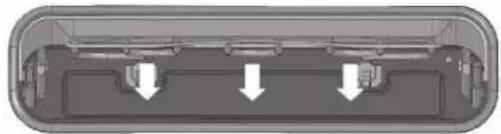
● The grill drawer door must be closed during grilling.
natural_image
Cross-sectional diagram of a device casing with internal components and directional arrows indicating flow or movement (no text or symbols)Using the grill
● Turn the grill control knob to adjust the temperature to get the desired result
● Preheat the grill. After 3 minutes, put food in.
● Note that put grease closed correctly in the (have screens on both sides).
- Close the grill drawer.
- In the process of grilling, slide out the grill drawer every 1-2 minutes to check progress.
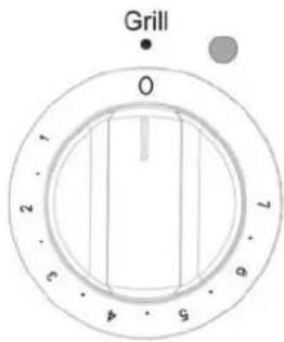
Handling grilling problems
| Problem Causes What to do | ||
| Grilled meats overcooked on outside and raw in centre | Meat too close to grill | Use inverted grill tray insert and/or reduce temperature setting |
| Excess grill smoke Build-up of | fats in grill | clean grill after every useTrim excess fat from meat prior to cooking |
| Grilled steaks and chops buckling | Cut fat with knife towards meat or remove all fat |
Using the hotplate burners of your gas cooker
The hob control knobs
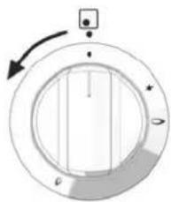
The symbols on the control knobs mean the following:
[NO TEXT]
No gas flow

Maximum gas flow
A
Minimum gas flow
natural_image
Circular mechanical component with internal structure and directional arrow (no text or symbols)NOTE: All operating positions must be set between the maximum and minimum flow settings, and never between the maximum setting and the closed position.
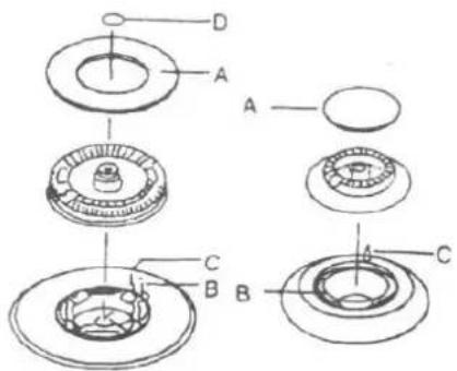
Introduction to the burner
A-Burner cap
B-Lighting plug
C-Thermocouple
D- Wok burner cap
Hotplate Ignition
To light these hotplates:
-
Choose the hotplate you want to use.
-
Turn the hotplate burner control knob to "
-
Press electronic igniter switch to release spark to the burner.
Bumers
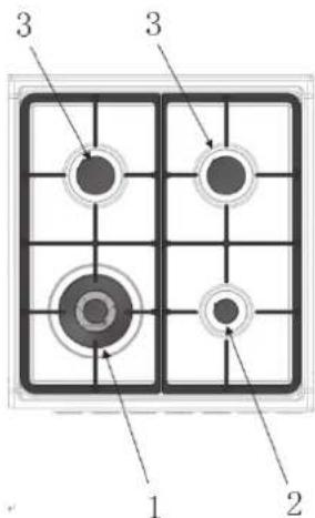
1、Wok burner
□ Used for fast heating.
☐ Used with large size pots and pans.
2、Small Burner
□ Used for simmering.
□ Used with small pots and pans.
3、Semi-rapid Burner (2 of)
□ Used for normal cooking.
□ Used with middle size pots and pans.
To conserve gas, place the pan centrally over the burner and adjust the flame so that it does not go past the edges of the cookware.
Fitting oven accessories and cleaning
Safety warnings about cleaning
● Always make sure that the cooker is turned off before cleaning.
● Always clean cooker immediately after use.
- Do not use steam cleaners. These may cause moisture build-up.
- Do not use caustic- based cleaners. These will damage aluminums parts, and remove enamel gloss.
Cleaning the enamel:
- Keep enamel clean by wiping it with a soft cloth dipped in warm soapy water.
- Rub difficult stains with a nylon scourer or creamed powder cleanser.
- Do not use abrasive cleaners, dry powder cleaners, steel wool or wax polishes.
- If you use an oven cleaner, then follow the instructions on the product carefully.
Cleaning the control panel:
- Make sure control knobs are in off position.
● Clean the control panel by wiping it with a soft cloth dipped in warm soapy water and squeezed dry.
Cleaning the Gas Hob
Removing the trivets (Refer Figure 1)
● The trivets locate in the recessed area of the hob.
- They can be removed for cleaning by carefully lifting them from the hob.
- Clean by washing in warm soapy water. Dry thoroughly.
● Take care when replacing the trivets as dropping them onto the hob may damage the enamelled surface.
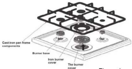
Figure 1
Removing the burners
● The burner caps and crowns are removable for cleaning.
- Flame port blockage should be removed by means of a match stick or brush.
- If the caps, crowns and cups are heavily soiled, use a non-abrasive cleaning compound.
- Do not clean them with abrasive or caustic type cleaners, or put in a dishwasher as they will be damaged.
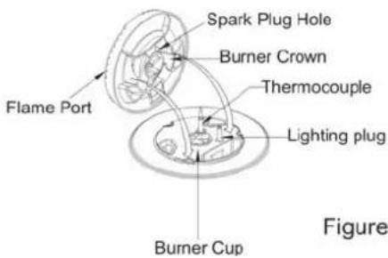
Figure 2
Refitting the burner crowns and caps
- The burner crown must be fitted correctly into the burner cup or damage will occur during operation.
- To do this, ensure that the 2 ribs on either side of the spark plug hole are positioned into the 2 slots on the burner cup. (See figure 2).
● The burner cap is simply positioned over the top of the burner crown.
Note: When the burner is correctly fitted it will sit level on the hob.
If ignition is difficult or falls after cleaning, then either bumer parts are not dry or parts have not been positioned correctly
Cleaning the grill compartment
- Lift the grill tray out.
- Clean the Grill Compartment with hot soapy water. If stronger action is needed use a nonabrasive oven cleaner applied with a nylon scourer.
Cleaning the Oven
- Open the door fully.
- Remove oven shelves and side racks.
- Clean in hot soapy water.
natural_image
Technical line drawing of a battery housing with internal components, shown in two views: top is exploded view, bottom is detailed detail (no text or symbols)Cleaning the oven door / How to remove the oven doors
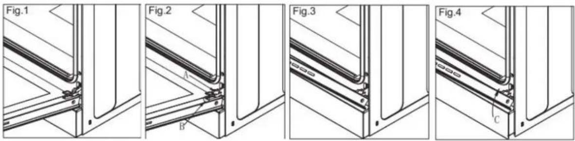
For a more thorough clean, you can remove and disassemble the oven door. Proceed as follows:
Oven door structures 1 remove and assemble procedure:
- Open the door to the full extent (fig.1);
- Open the lever A completely on the left and right hinges (fig.2);
- Hold the door as shown in fig.3
● Gently close the door (fig.3) until left and right hinge levers A are hooked to part B of the door (fig.4). - Withdraw the hinge hooks from their location following arrow C (fig.4);
- Rest the door on a soft surface;
- To replace the door, repeat the above steps in reverse order.
Removing the Inner Pane of Glass
● Double oven door: Remove the seal G by unscrew the no.2 bolts (fig.1)
● Gently pull out the inner pane of glass (fig.2)
- Clean the glass with an appropriate cleaner. Dry thoroughly, and place on a soft surface.
- Now you can also clean the inside of the outer glass.
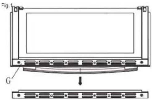
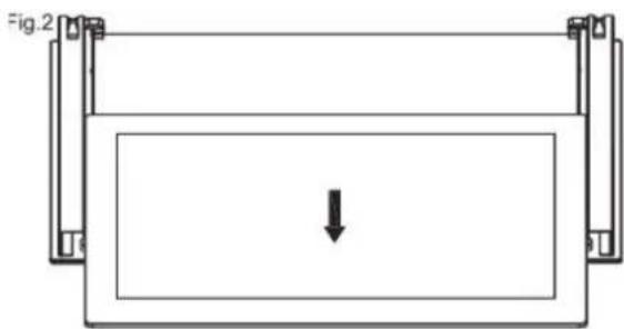
natural_image
Simple line drawing of a rectangular frame with a downward arrow inside, no text or symbols presentCleaning the door glass
- Clean the glass door using non-abrasive products or sponges and dry it with a soft cloth.
- Do not use the oven without the inner door glass fitted.
- Do not use harsh abrasive cleaners or sharp metal scrapers to clean the oven door glass since they can scratch the surface, which may result in shattering of the glass.
Replacing the Oven Lamp
- Disconnect the oven from the power supply at the fuse-box by means of the switch used to connect the appliance to the electrical mains; or unplug the appliance (gas)
- Remove the glass cover of the lamp-holder by rotating anti-clockwise
- Remove the lamp and replace with a lamp resistant to high temperatures (300°C) with the following characteristics:
Voltage: 220-240V
Wattage: 25W
Type: E 14
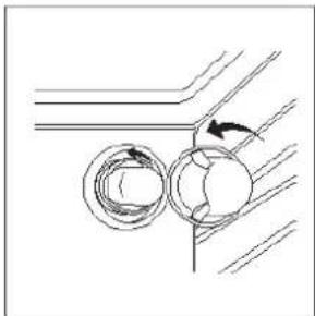
natural_image
Diagram showing two circular components with directional arrows, no text or symbols presentReplace the glass cover. Reconnect the appliance to the mains power supply.
Solving Problems
If you have a problem with your appliance, check the table below before calling service. You may be able to avoid a service call by and avoid unnecessary inconvenience and expense.
For cooking problems, refer to Understanding Baking Problems.
| Problem Causes What to do | ||
| No spark obtained when gas burner knob is pushed / turned | Power not turned on Switch on electricity | |
| Household fuse blown Check fuses | ||
| Circuit breaker tripped Check circuit breaker | ||
| Spark plug is wet or dirty Dry or clean spark plug | ||
| Burner will not light even though spark can be seen/heard | Gas supply valve is turned off Turn on gas supply | |
| burner crown & cap not positioned correctly | Remove parts and refit carefully | |
| Port blockage in ignition area Make sure that ports and ignition area are clean and dry | ||
| Oven light not working | Power not turned on Switch on electricity | |
| Household fuse blown Check fuses | ||
| Circuit breaker tripped Check circuit breaker | ||
| Lamp blown or loose in socket Replace or tighten globe | ||
| Oven not hot enough | Heat escaping through incorrectly sealed door | Check shelves or dishes are not preventing door closing properly, Check that door is fitted properly after door removal for cleaning |
| Door seal is worn or has moved Replace seal or refit it | ||
| The burner has not lit Stop trying, leave the oven door open and wait 1 minute before trying again | ||
| Digital timer display flashing | Power failure or interruption | Reset time of day |
| Household fuse blown or power supply is off | Check fuses, power supply | |
| Unit smoking when first used | Protective oils being removed | This is normal |
| Odour on first use of oven | This is normal | |
| Allow 2-4 hours for odour to dissipate (open all windows) | ||
| 120 minute timer buzzer not audible | Timer not wound sufficiently | Turn timer knob past 15 minute mark Then turn to the required number of minutes |
| Oven shelf tight | Oven shelf not inserted correctly, may be upside down or back to front | Remove shelf and insert as per diagram |
| Clock display off | Household fuse blown or power supply is off | Check fuses, power supply |
Note: Only service centers should carry out servicing. Otherwise warranty may be void.
Installing cooker - power connections
Fitting on a Power Supply Cable
Connecting appropriate power supply ` terminal board/ connector block:
- Using a screwdriver,prize open tabs of the Terminal board cover.
- Remove the wire clamp screw.
- Fasten the wires beneath the corresponding screw heads, using brass 'bridge' for single phase supply.
- Fasten cable clamp and close the cover of the terminal board.
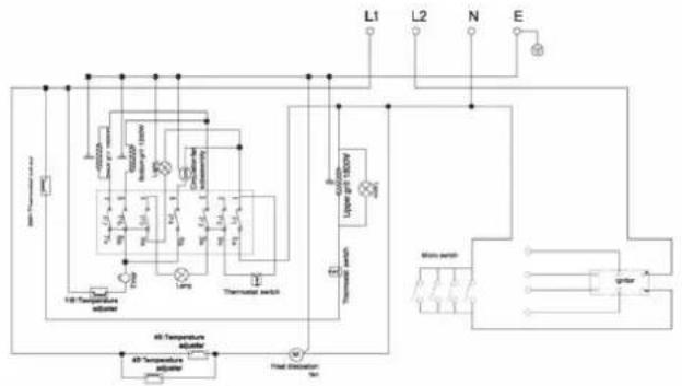
- The ac power supply should be 220-240 V, 50/60 Hz. For electric cookers, the minimum 45A fuse, or at least 45A a distribution circuit breaker. For gas cookers, the minimum 10A fuse, or at least 10A circuit breaker.
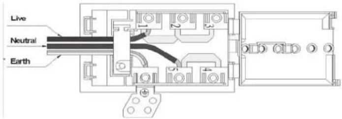
| 1N~ | |
| 2N~ | |
| 3N~ |
Warning: Connect the power cord must be in accordance with the instructions listed in the table below
| Wire cross-sectional area(mm2) Connection mode | L1 | L2 | L3 | N | E |
| 1N- | Min1.5 | — | — | Min1.5 | Min1.5 |
| 2N- | Min1.5 | Min1.5 | — | Min1.5 | Min1.5 |
| 3N- | Min1.5 | Min1.5 Min1.5 | MinMinMin1.5 | Min1.5 | Min1.5 |
Connecting the supply cable to the mains
Install an approved circuit breaker with a minimum contact opening of 3 mm, between the appliance and the mains fuse box. The circuit breaker should be sized according to the load and should comply with current regulations (the earth wire should not be interrupted by the circuit breaker).
The supply cable should be positioned so that it does not reach a temperature of more than 50°C with respect to the room temperature, anywhere along its length Before switching fuse ON in meter-box check:
- Earth continuity. The electrical safety of this appliance can only be guaranteed if the cooker is correctly installed and earthed, in compliance with regulations on electrical installations.
- The electrical capacity of the system and sockets will support the maximum power of the appliance, as indicated on the data plate
- Go to section "Installing your new cooker"
flowchart
graph TD
    A["Power Source"] --> B["Thermometer switch"]
    B --> C["Thermal relay"]
    C --> D["Upper gelt 130V"]
    C --> E["Lower gelt 130V"]
    D --> F["Main system"]
    E --> F
    F --> G["Output"]
    H["50kΩ/100kΩ"] --> I["Thermometer switch"]
    I --> J["Thermal relay"]
    J --> K["Output"]
    L["60kΩ/100kΩ"] --> M["Thermometer switch"]
    M --> N["Thermal relay"]
    N --> O["Output"]
    P["Ground"] --> Q["Ground"]
    R["L1"] --> S["L2"] --> T["N"] --> U["E"]
Installation of the anti-tilt plate
● Determine position of cooker and ant-tilt plate.
- Securely fix the anti-tilt plate to the floor with appropriate fasteners.
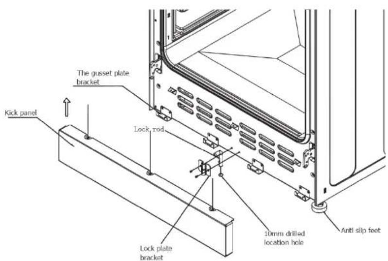
- Remove front kick plate to obtain access to stability bolt, by removing screws from top of the kick plate. Removing the oven door will make this procedure easier.
- Fasten the stability bolt bracket to the front frame with the 2 screws supplied.
- Reposition the cooker back into the anti-tilt plate and then mark the position of the stability bolt hole.
- Pull the cooker back out and drill the bolt location hole. Use a 10mm masonry or wood drill. When drilling into concrete ensure a minimum hole depth of 30mm.
- Reposition the cooker back into the anti-tilt plate, aligning the stability bolt bracket with the 10mm drilled hole. Then slide the bolt through the bracket and into the hole.
- Connect Electricity supply/gas supply but do not turn on until installation is completed.
- Slide the cooker back into the anti-tilt plate so that rear cover rests against the rear wall. Then check the height and level of the cooker. If required, pull the cooker back out and adjust the leveling feet as required.
● Re-fit kick plate as per the illustration below
Installing the gas cooker
Unpacking
When packaging is removed from product you will notice there are several items nested in the packaging base. The burner crowns, burner caps and trivets to be fitted to the hob.
Note: That Wok trivet is a different size and must be correctly located over Wok burner.
Locating the cooker
This appliance must be installed by an authorised person in accordance with this instruction manual, AS/NZS 5601 – Gas installations (installation and pipe sizing), local gas fitting regulations, local electrical regulations, local water regulations, local health regulations, Building Code of Australia and any other government authority.
Overhead clearances—(Measurement A) Range hoods and exhaust fans shall be installed in accordance with the manufacturer's
relevant instructions. However, in no case shall the clearance between the highest part of the hob of the gas cooking appliance and a range hood be less than 600 mm or, for an overhead exhaust fan, 750 mm. Side clearances—(Measurements B, E, C) Where B, measured from the periphery of the nearest burner to any vertical combustible surface, or vertical combustible surface covered with toughened glass or sheet metal, is less than 200 mm, the surface shall be protected to a height C of not less than 150 mm above the hob for the full dimension (width or depth) of the cooking surface area. Where the gas cooking appliance is fitted with a 'splashback', protection of the rear wall is not required.
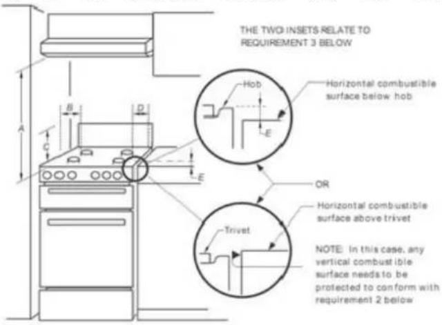
Additional requirements for freestanding and elevated gas cooking appliances—(Measurements D & E). Where D, the distance from the periphery of the nearest burner to a horizontal combustible surface is less than 200 mm, then E shall be 10 mm or more, or the horizontal surface shall be above the trivet.
Gas type
Before installation check that the cooker is suitable for the gas supply. The cookers are manufactured for both Natural gas or Universal LPG, check the gas type label located on appliance. If the cooker is required to be converted to a different gas type, a conversion kit can be obtained by contacting the Customer Care Centre.
Connection to the gas supply
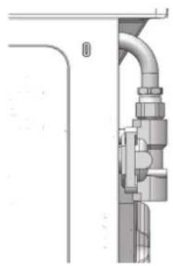
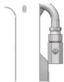
The isolating manual shut-off valve connection point must be installed and accessible when the appliance is in position. Gas inlet is located at the top rear right hand side, 50mm from the edge. This appliance is suitable for connection with rigid pipe or flexible hose. For flexible hose connection, the flexible hose assembly must be certified to AS/NZS 1869 class B or D, be of appropriate internal diameter for the total gas consumption, be kept as short as possible (not exceeding 1200mm), must not be in contact with the floor or any hot or sharp surfaces. The hose assembly must not be subject to strain, abrasion, kinking or deformation.
Gas connection
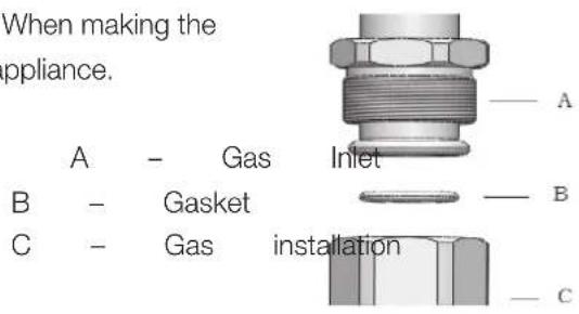
The gas inlet connection of the appliance has a “male thread.” When making the connection, take care not to apply stresses of any kind to the appliance.
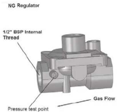
Natural Gas; the supplied regulator must be fitted to the appliance inlet connection. Gas pressure must be adjusted to 1.0 kPa when the auxiliary, semi rapid and rapid burners are set to high flame, the appliance test point is located on the regulator.
natural_image
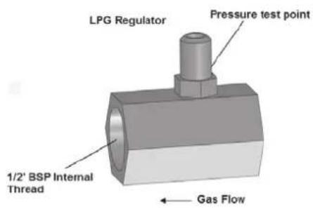
Technical diagram of a pipe connection with mechanical components (no text or symbols visible)LPG: the supplied test point adaptor must be fitted to the appliance inlet connection. Gas pressure must be adjusted to 2.75 kPa, when the auxiliary, semi rapid and rapid burners are set to high flame, the appliance test point is located on the test point adaptor.
natural_image
Technical illustration of a pipe fitting with a valve and bracket (no text or symbols)
When the installation is complete, always performance a gas leakage check that all the unions are absolutely tight using a soapy solution. Never use a flame to make this check.
Safety warnings about installation
● The cooker must be installed and serviced only by an authorized person.
● A certificate of compliance must be supplied by Installer and is to be kept by the customer.
- The packing materials must be removed before you install the cooker.
- You must follow the installation instructions in this booklet and AS/NZS 5601
● The flexible pipe for gas models must have sufficient loops so the cooker can be moved for service.
● The vents; openings and air spaces must not be blocked.
● The anti-tilt plate must be installed to avoid accidental tipping.
- The stabilizing bolt must be installed to avoid accidental moving.
- You must not pull the cooker by the door handles.
- Power socket, if provided for gas models, and electricity isolation switch for electric models and gas models without a 20A plug, is to be installed in an accessible position near the cooker (but not behind cooker).
- If the supply cord or cable is damaged, it must be replaced by an approved service agent or a similarly qualified person in order to avoid a hazard.
Note: To ensure cooker stable, both the anti-tilt plate and anti-movement/ stability bolts must be installed on all cookers.
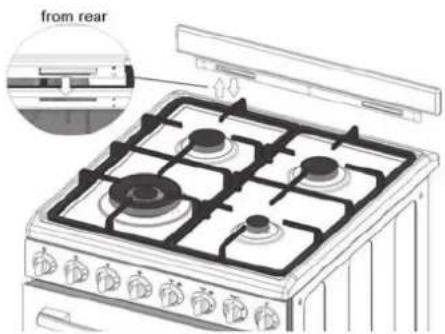
The installation the splash back
Upon unpacking cooker, using a philips head screwdriver to remove splash back from rear of cooker.
☐ Position splash back into tabs at rear of cooker and push downwards gently until properly in position.
☐ Screw in splash back from behind to secure in place.
Testing the operation of the gas cooker
Gas leakage and operation of the appliance must be tested by the installer before leaving. Check all burner flames are blue in colour, stable and completely ignite at both high and low flame settings with no appreciable yellow tipping, carbon deposition, lifting, floating, lighting back or objectionable odour. Test burners individually and in combination.
When maximum flame appearance is correct, then check the turn-down setting on each burner. If the settings appear to be incorrect, proceed as follows:
- Adjust the bypass screw mounted on the body of each hotplate control cock. This is accessible when the control knob and the control panel are removed.
- Check the ignition on all burners both separately and in combination.
- Check the operation of the electrical components, if applicable.
- If you are satisfied that the cooker is operating correctly, then turn it off and show the customer how to use it. Make sure you ask the customer to operate the clock and controls.
Where the data plate is obscured by cabinetry when the cooker is in the installed position, place the supplied duplicate data plate to a suitable adjacent surface or within the instruction manual for future reference.
Gas Type: Natural Gas @1.00kPa Test Point | Pressure
| Burner Injector Size (mm) | N.G.C. (MU/ft) | ||
| Wok 1.75mm 13.68 | 1.75mm | 13.68 | |
| Semi-rapid 1.16mm | 6.30 | 1.16mm | 6.30 |
| Auxiliary 0.93mm | 3.60 | 0.93mm | 3.60 |
| Oven 1.40mm 9.0 | 1.40mm | 9.0 | |
ULPG @ 2.75kPa Test Point Pressure
| Burner | Injector-Side(nm) | NGCQ(MW/d)h |
| Wok | 1.10mm 13.68 | 13.68 |
| Semi-rapid | 0.71mm 6.30 | 6.30 |
Technical specifications
| Model | FGO54W, GG54GOW |
| oven capacity(L) | 70 |
| grill capacity(L) | 20 |
| voltage(v) | 220-240 |
| frequency (Hz) | 50/60 |
| circuit breaker(A) | 10 |
| grill power (W) | 1650-1800 |
| product dimension (mm) | 540*630*910 |
| package size (mm) | 636*740*976 |
| gross/net weight (Kg) | 49.5/57 |
Total Gas Consumption:
| Model | Natural Gas(MJ/h) | UUPG(MJ/h) |
| Hob Model | 29.88 29.88 | 29.88 |
| Oven Model | 38.88 38.88 | 38.88 |
Gas Type::Natural Gas@1.00kPa Test Point Pressure
| Burner Injector Size (mm) | N.G.C. (MU/h) | ||
| Wok 1.75mm | 3.68 | 1.75mm | 13.68 |
| Semi-rapid 1.16mm | 6.30 | 1.16mm | 6.30 |
| Auxiliary 0.93mm | 3.60 | 0.93mm | 3.60 |
| Oven 1.40mm | 9.0 | 1.40mm | 9.0 |
ULPG @ 2.75kPa Test Point Pressure
| Burner Injector Size (mm) | tor Size N.G.C. (MJ/h) | N.G.C. (MJ/h) |
| Wok | 1.10mm 13.68 | 13.68 |
| Semi-rapid | 0.71mm | 6300 |
| Auxiliary 0.57mm | 3.60 0.57mm | 3.60 |
| Oven | 0.82mm 9.0 | 9.0 |
THIS SECTION HAS BEEN LEFT BLANK INTENTIONALLY
Euromaid
Distributed by
Home Appliance Pty Ltd
20 Carlotta Street, Artarmon NSW 2064 AUSTRALIA
After Sales Service - 1800 444 357
www.euromaid.com.au
Distributed by:
Home Appliances Pty. Ltd.
20 Carlotta Street, Artarmon NSW 2064
Tel: 02 9958 3111 Fax: 02 9958 3555
Email: info@hapl.com.au
Website: www.hapl.com.au
- contents
- Conditions Of Use
- Safety Precautions
- Other Important Safety Information
- Warnings for use of grill, oven, and appliance hob
- Grill warnings
- Oven warnings
- Disposal of packaging
- Installation, Cleaning and Servicing
- Product description
- Description of gas cooker
- Description of front panel
- Controls
- First time use the appliance
- Fitting oven shelves
- Preparing your appliance for the first time
- Using the oven
- Oven safety warnings
- Using the oven of your gas cooker
- 2) Set cooking time
- Using the gas oven
- Oven cooking guide
- Using the grill
- Grill safety warnings
- Grill information
- Using the hotplate burners of your gas cooker
- The hob control knobs
- Introduction to the burner
- Hotplate Ignition
- Bumers
- Fitting oven accessories and cleaning
- Safety warnings about cleaning
- Cleaning the enamel:
- Cleaning the control panel:
- Cleaning the Gas Hob
- Removing the trivets (Refer Figure 1)
- Removing the burners
- Refitting the burner crowns and caps
- Cleaning the grill compartment
- Cleaning the Oven
- Cleaning the oven door / How to remove the oven doors
- Removing the Inner Pane of Glass
- Cleaning the door glass
- Replacing the Oven Lamp
- Solving Problems
- Installing cooker - power connections
- Fitting on a Power Supply Cable
- Connecting the supply cable to the mains
- Installation of the anti-tilt plate
- Installing the gas cooker
- Unpacking
- Locating the cooker
- Gas type
- Connection to the gas supply
- Gas connection
- Safety warnings about installation
- The installation the splash back
- Testing the operation of the gas cooker
- Euromaid
Brand : Euromaid
Model : FSG54S
Category : Oven