
HC60PCHTX2 - Range hood Fisher & Paykel - Free user manual and instructions
Find the device manual for free HC60PCHTX2 Fisher & Paykel in PDF.


| Product Type | Range Hood |
| Brand | Fisher & Paykel |
| Model | HC60PCHTX2 |
| Width | 60 cm (23.6 in) |
| Height (min - max) | 65 - 115 cm (25.6 - 45.3 in) |
| Depth | 50 cm (19.7 in) |
| Weight | Approximately 15 kg (33 lb) |
| Power Supply | 220-240 V, 50 Hz |
| Maximum Extraction Rate | 620 m³/h |
| Noise Level (max) | 65 dB(A) |
| Lighting | 2 x 3 W LED |
| Controls | Electronic push button |
| Number of Speeds | 3 + Boost |
| Grease Filter Type | Aluminum mesh |
| Carbon Filter Option | Yes (sold separately) |
| Ducting | 150 mm (6 in) outlet |
| Recirculation Mode | Possible with carbon filter |
| Energy Class | A |
| Safety Features | Auto shut-off, thermal protection |
| Spare Parts Available | Filters, LED lamps, control board |
| Repairability Index | 8/10 |
| Warranty | 2 years |
Frequently Asked Questions - HC60PCHTX2 Fisher & Paykel
User questions about HC60PCHTX2 Fisher & Paykel
0 question about this device. Answer the ones you know or ask your own.
Ask a new question about this device
Download the instructions for your Range hood in PDF format for free! Find your manual HC60PCHTX2 - Fisher & Paykel and take your electronic device back in hand. On this page are published all the documents necessary for the use of your device. HC60PCHTX2 by Fisher & Paykel.
USER MANUAL HC60PCHTX2 Fisher & Paykel
Installation instructions and User guide
NZ AU
_
| _
一
1
Contents
Safety and warnings
Installation instructions 3
Getting started quickly 8
Cleaning and maintenance
Manufacturer's warranty 11
Customer care 12
2
9
Important!
SAVE THESE INSTRUCTIONS
The models shown in this User Guide may not be available in all markets and are subject to change at any time. For current details about model and specification availability in your country, please visit our local website listed on the back cover or contact your local Fisher & Paykel dealer.
2 Safety and warnings
Important!
Please read the entire set of instructions before installing the wall canopy.
This wall canopy is not intended for use by young children or infirm persons without supervision.
- Young children should be supervised to ensure that they do not play with the wall canopy.
There must be adequate ventilation of the room when the wall canopy is used at the same time as appliances burning gas or other fuels. (A partial vacuum in the room could result in too high a concentration of gas in the air).
- You must read the details concerning the method and frequency of cleaning.
There is a fire risk if cleaning is not carried out in accordance with the instructions.
- Do not flambé under the wall canopy.
- Exhaust air must not be discharged into an existing flue that is used for exhausting fumes from appliances burning gas or other fuels.
- The minimum distance between the cooktop surface and the filters of the wall canopy shall be 600 mm, or 650 mm if installed over a gas cooktop.
- Attention should be given to ensure that any applicable regulations concerning the discharge of exhaust air is fulfilled.
If the supply cord of this equipment is damaged it must only be replaced by the manufacturer, its service agent or similarly qualified person in order to avoid a hazard.
■ Always switch the power off prior to installation, servicing or cleaning the wall canopy.
■ Never use the wall canopy without the filters in place.
- A power outlet should be within 750 mm of the motor assembly and can be either on the wall, behind the chimney or in the ceiling.
- To comply with electrical safety regulations, this canopy must be plugged into a socket near the appliance. The socket must be accessible, or have an accessible isolating switch, to enable the end user to isolate the canopy from the power for the purpose of internal cleaning or maintenance.
- Ducting accessories are not supplied. All ducting must comply with local requirements and building codes.
WARNING!

Electrical Shock Hazard
All electrical work must be done in accordance with local and/or national electrical codes as applicable. For safety, this product must be earthed. If you are unfamiliar with methods of installing electrical wiring, employ the services of a qualified electrician. Turn off power at service entrance before installing wiring or servicing this product.
WARNING!
8.8 kg
(HC60)
10.7 kg
(HC90)
Weight Hazard
The wall canopy is heavy. Please ensure adequate care is taken when installing the wall canopy to prevent personal injury. The wall canopy must be installed onto a solid wall, stud, beam or truss. Weight of the product is 8.8 kg/10.7 kg.
Contents of packaging
1 x wall canopy
■ 2 x chimney flues with bracket
■ 1 x installation instructions
■ 2 x aluminium mesh filters (HC60PCHTX2)
■ 3 x aluminium mesh filters (HC90PCHTX2)
2 x butterfly flaps
■ 4 x small screws, to secure chimney flue
5 x 8 x 1½" wood screws
■ 1 x washer (5 mm inner diameter)
natural_image
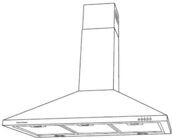
Line drawing of a kitchen air conditioner unit with conical top and base (no text or symbols)Fig.1 Wall canopy
Typical equipment required:
Electric drill
Screwdriver
Duct tape
Jig saw
Ladder
Ducting
- Tape measure
Drill bits
Spirit level
Accessories
| Accessory | Part Number |
| Chimney ext (740 mm) SS 791989 | |
| Light bulb 12V Halogen/Max 20W | |
| Charcoal filter (HC60) 790681 | |
| Replacement aluminium filter (HC60) 790682 | |
| Charcoal filter (HC90) 790683 | |
| Replacement aluminium filter (HC90) 790684 |
4 Installation instructions
Height of wall canopy
- Where an electric cooktop is installed beneath the wall canopy, the distance between the top of the cooktop and the underside of the range hood must be a minimum of 600 mm and a maximum of 700 mm.
- Where a gas fuelled cooktop is installed beneath the wall canopy, the distance between the top of the pot rests and the underside of the rangehood must be a minimum of 650 mm and a maximum of 750 mm.
Note: your relevant gas or local building authority may specify different height requirements. Care should be taken to comply with any applicable regulations concerning the discharge of exhaust air.
Ducting options
Note: if you wish to have the flue run all the way to the ceiling, please ensure that you work your measurements out fully before attempting the installation. In some instances, extra lengths of flue or a customised flue maybe required. A 740 mm flue extension is available as an accessory part for use where ceiling height is above 2440 mm. (Part no. 791989)
Recirculation
For recirculation, please purchase charcoal filters, which are fitted in place of the aluminium filters supplied with the hood. The charcoal filters purify the air before allowing the air to return back to the kitchen through the air vents in the sides of the chimney flue.
Note: a ducting hole is not required in the wall or ceiling if the canopy is fitted with charcoal filters.
Ducting
For ducted installation, it is recommended that you use 150 mm diameter, rigid or semi-rigid ducting. To accommodate the 150 mm ducting, a ceiling hole should be carefully measured and cut out, 160 mm (min) in diameter, with a centre line 100 mm from the edge of the wall.
Efficiencies in the performance of your canopy are enhanced by the use of smooth, straight and short ducting options.
We recommend using solid, galvanised or plastic, smooth-walled ducting which helps to reduce noise and increase airflow.
The use of flexible ducting is not recommended. If there is no other option available, the flexible ducting must be pulled as tight as possible.
All ducting must comply with local requirements and building codes.
Note: we recommend an Easy Fit by Fisher & Paykel or a UNIDUCT ducting system, products that have been designed to expel air efficiently.
Installation instructions
5
Preparing the wall canopy for installation
Before installing the wall canopy, please carefully read through the installation instructions in full.
- Prior to drilling any holes, check that the area behind the surface to be drilled is clear of any electrical cables or pipes etc.
Take care when installing the wall canopy as stainless steel is easily damaged during installation if scratched or knocked by tools.
- Protect the cooktop below, using cardboard or a similar protective cover, to prevent damage on installation.
6 Installation instructions
1 Establish the desired height of the rangehood above the benchtop according to the 'Installation height requirements' above. Measure this distance from the top of the benchtop and, using a spirit level, draw a light horizontal line on the wall. Make sure that the line can easily be erased or will be hidden after installation. This is where the bottom of the rangehood will sit (Fig.2).
2 Mark the position of the rangehood on the wall. Using a spirit level, also mark a vertical line intersecting the horizontal line, (ensuring that the line can easily be erased or will be hidden after installation) showing the position where the centre of the rangehood will be. This is normally over the centre of the cooktop (Fig.3).
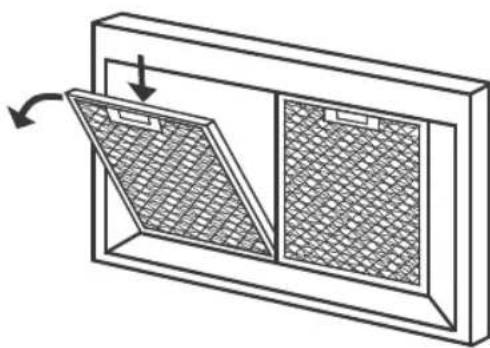
3 Remove the grease filters (this is to make installation easier). Press inward on the catch, found on the handle, and pull the filter downward (Fig.4).
4 Determine location of the fixing "keyholes" on the wall. The hood is secured to the wall by two "keyholes" located above the motor behind the air exit opening. From the point where the horizontal and vertical lines drawn earlier intercept, use a spirit level and pencil and draw another horizontal line 290mm above the first horizontal line (ensuring that the line can easily be erased or the line will be hidden after installation) as shown in Fig.5. This now indicates where the top of the "fixing keyholes" are. Where the vertical line meets the top horizontal line (just drawn), measure and mark both sides of the vertical line, showing where to drill.
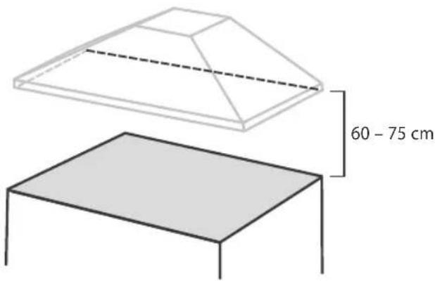
Fig.2 Establishing height of rangehood
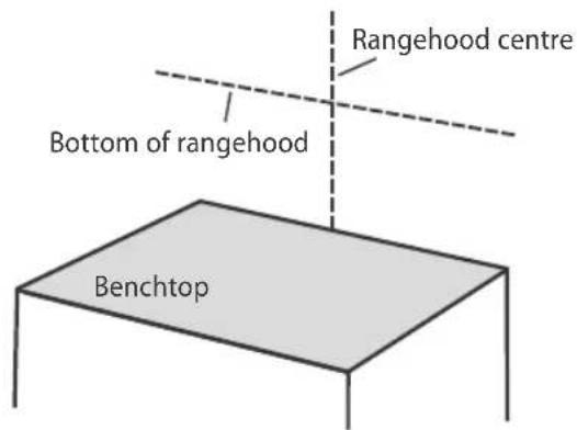
Fig.3 Marking the position of the rangehood on the wall
natural_image
Diagram of a window with grating and mesh panels, showing directional arrows (no text or symbols)Fig.4 Removing the grease filters
Installationinstructions
7
5 Drill holes and secure the rangehood to the wall. Depending on the wall type (concrete, drywall etc) drill/screw appropriate fittings in the two locations just marked. The rangehood should now be able to be hung on these bolts/ screws through the two keyholes in the hood.
6 Create additional means of attachment. Keyholes alone are insufficient means of attachment. Drill two extra holes in the back panel, put screws in with an anchor (if required) to ensure proper attachment and fix the rangehood by these screws as well, as shown in Fig.6. Ensure all fixings are secure.
7 If ducting externally, assemble and fit ducting as per manufacturer's instruction.
Optional: If desired, the one-way butterfly valve can now be fitted to the exit opening of the rangehood by simply snapping the two pieces into place.
8 Test the operation of the rangehood. Plug the rangehood in and test its operation on all speed levels. This will ensure that any imperfections in the installation, such as unwanted sounds or lack of suction can be addressed before the flue is in place. Over 95% of service calls are a result of faulty installation. Please be aware that in the event of a service call for a faulty installation, you will be charged as this is not covered under the manufacturer's warranty.
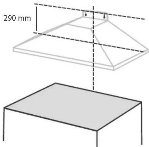
Fig.5 Determining location of the two fixing "keyholes"
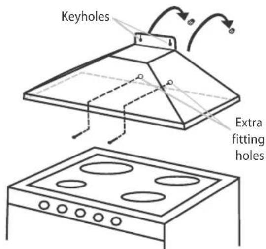
Fig.6 Creating additional means of attachment
9 Position and secure the flue. Secure the top mounting bracket at the highest possible point on the ceiling using a single screw through the supplied bracket. Ensure all ducting is fitted and electrical connections are secured correctly and switched on. Place the bottom part of the flue onto the rangehood and slide the upper flue piece inside the lower piece so the tabs "hug" the folded edge of the flue. Raise the upper part of the flue to the required height and, using the four screws supplied, secure the upper flue to the bracket on the wall.
Installation is now complete.
8 Getting started quickly
Control panel
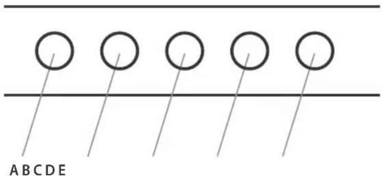
Fig.7 Control buttons
A = ALL OFF
B = Low speed motor ON/OFF
C = Medium speed switch ON/OFF
D = High speed switch ON/OFF
E = Lights ON/OFF
Caution!
Never use abrasive or oil based liquid cleaners.
General maintenance
The manufacturer is not liable for any damage caused by not following these instructions.
The wall canopy should be cleaned regularly using warm water with soap or mild liquid detergents. This ensures that no build-up of grease occurs as these deposits are corrosive. Do not use abrasives or harsh detergents/cleaning fluids.
Note: in areas of high humidity and coastal environments, cleaning should be carried out frequently.
Grease deposit container
Your wall canopy is fitted with a clear container located underneath the motor housing, that is only visible when the grease filters are removed.
Over time, oil, fat and grease, that is normally deposited inside the motor casing, is directed into this container for easy cleaning.
This unique design will help ensure your wall canopy remains in peak condition by minimising the amount of fat or grease collected in the motor.
Note:
This container should be cleaned as necessary, usually on an annual basis.
■ Always ensure the container is in place prior to using the wall canopy.
- Do not attempt to block the hole in the motor casing.
Aluminium filters
The grease filters must be periodically cleaned (at least every two months).
Remove the grease filters and wash them either by hand using hot soapy water or place them in the dishwasher using mild detergent. Badly smoked filters may be cleaned with "cookware cleaners".
Note: some discolouration of the frame may occur.
Charcoal filters
Charcoal filters are designed to remove grease and odours from cooking vapours, prior to the cleansed air re-entering the kitchen (when the wall canopy is in recirculating mode). Charcoal filters are disposable items and it is recommended that these should be replaced every three to six months depending on use.
Note:
- Fully saturated charcoal filters can become a barrier to air movement, impeding the wall canopy's performance.
In the event of fire, fully grease laden filters could be flammable and therefore regular replacement is recommended.
In ducted installations, conventional aluminium filters are recommended.
For replacement charcoal filters, ducting accessories, spare parts and service, please contact your local supplier or Fisher & Paykel Customer Care Centre.
10
Cleaning and maintenance
Light bulb replacement
(Halogen bulb 12 Volts/20 Watt)
1 Switch off the power to the canopy hood.
2 Use a small bladed screwdriver to prise off the light cover, taking care not to damage the surrounding material.
3 Remove the defective bulb from the canopy hood.
4 Replace with a new bulb using a cloth. Do not touch the bulb with fingers as this will shorten the life of the bulb.
5 Snap the cover back into place.
Note: replacement bulbs are not covered by warranty.
Manufacturer's warranty
You automatically receive a 2 year Manufacturer's Warranty with the purchase of this Product covering parts and labour for servicing within the country of purchase.
Fisher & Paykel undertakes to:
Repair or, at its option, replace without cost to the owner either for material or labour any part of the Product, the serial number of which appears on the Product, which is found to be defective within TWO YEARS of the date of purchase.
Note
This Warranty is an extra benefit and does not affect your legal rights.
This Warranty DOES NOT cover
A Service calls which are not related to any defect in the Product. The cost of a service call will be charged if the problem is not found to be a Product fault. For example:
- Correcting the installation of the Product.
- Instructing you how to use the Product.
- Replacing house fuses or correcting house wiring or plumbing.
- Correcting fault(s) caused by the user.
- Noise or vibration that is considered normal, eg drain/fan sounds, refrigeration noises or user warning beeps.
- Correcting damage caused by pests, eg rats, cockroaches, etc.
- Replacement light bulbs.
B Defects caused by factors other than:
-
Normal domestic use or
-
Use in accordance with the Product's User Guide.
C Defects to the Product caused by accident, neglect, misuse or Act of God.
D The cost of repairs carried out by non-authorised repairers or the cost of correcting such unauthorised repairs.
E Normal recommended maintenance as set out in the Product's User Guide.
F Repairs when the appliance has been dismantled, repaired or serviced by other than a Fisher & Paykel Authorised Repairer or the selling dealer.
G Pick-up and delivery.
H Transportation or travelling costs involved in the repair when the Product is installed outside the Fisher & Paykel Authorised Repairer's normal service area.
This Product has been designed for use in a normal domestic (residential) environment. This Product is not designed for commercial use (whatsoever). Any commercial use by a Customer will affect this Product's Warranty.
Service under this Manufacturer's Warranty must be provided by a Fisher & Paykel Authorised Repairer (refer to the 'Customer care' section at the back of this book). Such service shall be provided during normal business hours. This Warranty certificate should be shown when making any claim.
For Australian Customers
This Warranty is an extra benefit and does not affect your legal rights. Our goods come with guarantees that cannot be excluded under the Australian Consumer Law. You are entitled to a replacement or refund for a major failure and for compensation for any other reasonably foreseeable loss or damage. You are also entitled to have the goods repaired or replaced if the goods fail to be of acceptable quality and the failure does not amount to a major failure.
Please keep this User Guide in a safe place.
12
Customer care
Before you call for service or assistance...
Check the things you can do yourself.
Refer to your User Guide and check:

1 Your appliance is correctly installed.
2 You are familiar with its normal operation.
If after checking these points you still need assistance, please refer to your nearest Fisher & Paykel Authorised Repairer, or contact us through our local website listed on the back cover.
In New Zealand if you need assistance...\*
Call your Fisher & Paykel retailer who is trained to provide information on your appliance, or if we can be of any further help, please contact our Customer Care Centre,
Toll Free: 0800 FP CARE or 0800 37 2273 Fax: (09) 273 0656
Email: customer.care@fp.co.nz Postal address: PO Box 58732, Botany, Manukau 2163
If you need service...\*
Fisher & Paykel has a network of independent Fisher & Paykel Authorised Repairers whose fully trained technicians can carry out any service necessary on your appliance. Your dealer or our Customer Care Centre can recommend a Fisher & Paykel Authorised Repairer in your area.
In Australia if you need assistance...\*
Call the Fisher & Paykel Customer Care Centre and talk to one of our Customer Care Consultants.
Toll Free: 1 300 650 590 Fax: (07) 3826 9298
Email: customer.care@fp.com.au Postal Address: PO Box 798, Cleveland QLD 4163
If you need service...\*
Fisher & Paykel has a network of qualified Fisher & Paykel Authorised Repairers responsible for servicing only Fisher & Paykel branded appliances. Our Customer Care Centre can recommend a qualified Fisher & Paykel Authorised Repairer in your area.
*If you call, write or contact our website please provide: your name and address, model number, serial number, date of purchase and a complete description of the problem. This information is needed in order to better respond to your request for assistance.
Product details
Fisher & Paykel Appliances, Ltd
Model/Serial No.
Date of Purchase Purchaser
Dealer Suburb
Town Country
_
| _
一
1
www.fisherpaykel.co.nz
www.fisherpaykel.com.au
Fisher&Paykel
Copyright © Fisher & Paykel 2011. All rights reserved.
The product specifications in this booklet apply to the specific products and models described at the date of issue. Under our policy of continuous product improvement, these specifications may change at any time. You should therefore check with your Dealer to ensure this booklet correctly describes the product currently available.
NZ AU 05.2011F&P PN - 791632 B
- Contents
- Important!
- SAVE THESE INSTRUCTIONS
- Safety and warnings
- WARNING!
- Electrical Shock Hazard
- Weight Hazard
- Contents of packaging
- Typical equipment required:
- Accessories
- Installation instructions
- Height of wall canopy
- Ducting options
- Recirculation
- Ducting
- Installation instructions
- Preparing the wall canopy for installation
- Installation instructions
- Installationinstructions
- Getting started quickly
- Caution!
- General maintenance
- Grease deposit container
- Note:
- Aluminium filters
- Charcoal filters
- Cleaning and maintenance
- Light bulb replacement
- Manufacturer's warranty
- Fisher & Paykel undertakes to:
- Note
- This Warranty DOES NOT cover
- For Australian Customers
- Customer care
- Before you call for service or assistance...
- In New Zealand if you need assistance...\*
- If you need service...\*
- In Australia if you need assistance...\*
- Product details
Brand : Fisher & Paykel
Model : HC60PCHTX2
Category : Range hood