
MSZ-AP80VGD - Air-conditioner MITSUBISHI - Free user manual and instructions
Find the device manual for free MSZ-AP80VGD MITSUBISHI in PDF.


| Product Type | Wall-mounted split system air conditioner |
| Brand | Mitsubishi Electric |
| Model | MSZ-AP80VGD |
| Cooling Capacity | 8.0 kW (27,300 BTU/h) |
| Heating Capacity | 9.0 kW (30,700 BTU/h) |
| Energy Efficiency (Cooling) | SEER up to 6.5 |
| Energy Efficiency (Heating) | COP up to 4.2 |
| Refrigerant | R32 |
| Indoor Unit Dimensions (WxHxD) | 798 x 299 x 189 mm |
| Indoor Unit Weight | 10.5 kg |
| Outdoor Unit Dimensions (WxHxD) | 800 x 550 x 285 mm |
| Outdoor Unit Weight | 34 kg |
| Power Supply | 220-240 V, 50/60 Hz |
| Sound Level (Indoor) | 26-45 dB(A) |
| Sound Level (Outdoor) | 50 dB(A) |
| Compressor Type | Inverter |
| Air Flow Rate (Cooling) | 600-780 m³/h |
| Air Filter | Washable anti-allergy enzyme filter |
| Special Functions | Plasma Quad Plus ionizer, self-cleaning, auto restart, 24-hour timer |
| Remote Control | IR with LCD display |
| Maintenance | Clean filter every 2 weeks; professional service recommended annually |
| Safety Features | Auto restart after power failure, overload protection, anti-freeze |
| Spare Parts & Repairability | Available through authorized service centers; common parts stocked |
Frequently Asked Questions - MSZ-AP80VGD MITSUBISHI
User questions about MSZ-AP80VGD MITSUBISHI
0 question about this device. Answer the ones you know or ask your own.
Ask a new question about this device
Download the instructions for your Air-conditioner in PDF format for free! Find your manual MSZ-AP80VGD - MITSUBISHI and take your electronic device back in hand. On this page are published all the documents necessary for the use of your device. MSZ-AP80VGD by MITSUBISHI.
USER MANUAL MSZ-AP80VGD MITSUBISHI
SPLIT-TYPE AIR CONDITIONERS
INDOOR UNIT
MSZ-AP60VGD MSZ-AP71VGD MSZ-AP80VGD MSZ-AP60VGKD MSZ-AP71VGKD MSZ-AP80VGKD
natural_image
Simple line drawing of a white rectangular container with no text or symbolsOPERATING INSTRUCTIONS
For user
- To use this unit correctly and safely, be sure to read these operating instructions before use.
English
CONTENTS
■SAFETY PRECAUTIONS 1
■NAME OF EACH PART 4
■AN SPEED AND AIRFLOW DIRECTION ADJUSTMENT 7
■LONG OPERATION 8
■POWERFUOPERATION 8
■SAVE OPERATION 8
Meanings of symbols displayed on indoor unit and/or outdoor unit
| WARNING(Risk of fire) | This unit uses a flammable refrigerant.If refrigerant leaks and comes in contact with fire or heating part, it will create harmful gas and there is risk of fire. | |
| Read the OPERATING INSTRUCTIONS carefully before operation. | ||
| Service personnel are required to carefully read the OPERATING INSTRUCTIONS and INSTALLATION MANUAL before operation. | ||
| Further information is available in the OPERATING INSTRUCTIONS, INSTALLATION MANUAL, and the like. | ||
- Since rotating parts and parts which could cause an electric shock are used in this product, be sure to read these "Safety Precautions" before use.
- Since the cautionary items shown here are important for safety, be sure to observe them.
- After reading this manual, keep it together with the installation manual in a handy place for easy reference.
- Be sure to receive a guarantee card from your dealer and check that the purchased date and shop name, etc. are entered correctly.
Marks and their meanings

WARNING :
Incorrect handling could cause serious hazard, death, serious injury, etc. with a high probability.

CAUTION :
Incorrect handling could cause serious hazard depending on the conditions.
Meanings of symbols used in this manual

Be sure not to do.

Be sure to follow the instruction.

Never insert your finger or stick, etc.

Never step onto the indoor/outdoor unit and do not put anything on them.

Danger of electric shock. Be careful.

Be sure to disconnect the power supply plug from the power outlet.

Be sure to shut off the power.

Risk of fire.

Never touch with wet hand.

Never splash water on the unit.
| WARNING | |
| Do not connect the power cord to an intermediate point, use an extension cord, or connect multiple devices to a single AC outlet. This may cause overheating, fire, or electric shock. | |
| Make sure the power plug is free of dirt and insert it securely into the outlet. A dirty plug may cause fire or electric shock. | |
| Do not bundle, pull, damage, or modify the power cord, and do not apply heat or place heavy objects on it. This may cause fire or electric shock. | |

Do not turn the breaker OFF/ON or disconnect/connect the power plug during operation.
- This may create sparks, which can cause fire. - After the indoor unit is switched OFF with the remote controller, make sure to turn the breaker OFF or disconnect the power plug.
Do not expose your body directly to cool air for a prolonged length of time.
• This could be detrimental to your health.
SAFETY PRECAUTIONS
| The unit should not be installed, relocated, disassembled, altered, or repaired by the user. An improperly handled air conditioner may cause fire, electric shock, injury, or water leakage, etc. Consult your dealer.If the power supply cord is damaged, it must be replaced by the manufacturer or its service agent in order to avoid a hazard. | |
| When installing, relocating, or servicing the unit, make sure that no substance other than the specified refrigerant (R32) enters the refrigerant circuit.Any presence of foreign substance such as air can cause abnormal pressure rise and may result in explosion or injury.The use of any refrigerant other than that specified for the system will cause mechanical failure, system malfunction, or unit breakdown. In the worst case, this could lead to a serious impediment to securing product safety. | |
| This appliance is not intended for use by persons (Including children) with reduced physical, sensory or mental capabilities, or lack of experience and knowledge, unless they have been given supervision or instruction concerning use of the appliance by a person responsible for their safety. | |
| Children should be supervised to ensure that they do not play with the appliance. | |
| Do not insert your finger, a stick, or other objects into the air inlet or outlet.This may cause injury, since the fan inside rotates at high speeds during operation. | |
| In case of an abnormal condition (such as a burning smell), stop the air conditioner and disconnect the power plug or turn the breaker OFF.A continued operation in the abnormal state may cause a malfunction, fire, or electric shock. In this case, consult your dealer. | |
| When the air conditioner does not cool or heat, there is a possibility of refrigerant leakage. If any refrigerant leakage is found, stop operations and ventilate the room well and consult your dealer immediately. If a repair involves recharging the unit with refrigerant, ask the service technician for details.The refrigerant used in the air conditioner is not harmful. Normally, it does not leak. However, if refrigerant leaks and comes in contact with fire or heating part of such a fan heater, kerosene heater, or cooking stove, it will create harmful gas and there is risk of fire. | |
| The user should never attempt to wash the inside of the indoor unit.Should the inside of the unit require cleaning, contact your dealer.Unsuitable detergent may cause damage to plastic material the unit, which may result in water leakage. Should detergent come in contact with electrical parts or the motor, it will result in a malfunction, smoke, or fire.The appliance shall be stored in a room without continuously operating ignition sources (for example: open flames, an operating gas appliance or an operating electric heater).Be aware that refrigerants may not contain an odour.Do not use means to accelerate the defrosting process or to clean the appliance, other than those recommended by the manufacturer.Do not pierce or burn. | |
| The indoor unit must be installed in rooms which exceed the floor space specified. Please consult your dealer.AP60 : 1.9 m2AP71/80 : 3.1 m2 | |
| This appliance is intended to be used by expert or trained users in shops, in light industry and on farms, or for commercial use by lay persons. | |
| CAUTION | |
| Do not touch the air inlet or the aluminum fins of the indoor/outdoor unit.This may cause injury. | |
| Do not use insecticides or flammable sprays on the unit.This may cause a fire or deformation of the unit. | |
| Do not expose pets or houseplants to direct airflow.This may cause injury to the pets or plants. | |
| Do not place other electric appliances or furniture under the indoor/outdoor unit.Water may drip down from the unit, which may cause malfunction. | |
| Do not leave the unit on a damaged installation stand.The unit may fall and cause injury. | |
| Do not step on an unstable bench to operate or clean the unit.This may cause injury if you fall down. | |
| Do not pull the power cord.This may cause a portion of the core wire to break, which may cause overheating or fire. | |
| Do not charge or disassemble the batteries, and do not throw them into a fire.This may cause the batteries to leak, or cause a fire or explosion. | |
| Do not operate the unit for more than 4 hours at high humidity (80% RH or more) and/or with windows or outside door left open.This may cause the water condensation in the air conditioner, which may drip down, wetting or damaging the furniture.The water condensation in the air conditioner may contribute to growth of fungi, such as mold. | |
| Do not use the unit for special purposes, such as storing food, raising animals, growing plants, or preserving precision devices or art objects.This may cause deterioration of quality, or harm to animals and plants. | |
| Do not expose combustion appliances to direct airflow.This may cause incomplete combustion. | |
| Never put batteries in your mouth for any reason to avoid accidental ingestion.Battery ingestion may cause choking and/or poisoning. | |
| !Inside | Before cleaning the unit, switch it OFF and disconnect the power plug or turn the breaker OFF.This may cause injury, since the fan inside rotates at high speeds during operation. |
| When the unit will be unused for a long time, disconnect the power plug or turn the breaker OFF.The unit may accumulate dirt, which may cause overheating or fire. | |
| Replace all batteries of the remote controller with new ones of the same type.Using an old battery together with a new one may cause overheating, leakage, or explosion. | |
| If the battery fluid comes in contact with your skin or clothes, wash them thoroughly with clean water.If the battery fluid comes in contact with your eyes, wash them thoroughly with clean water and immediately seek medical attention. | |
| Ensure that the area is well-ventilated when the unit is operated together with a combustion appliance.Inadequate ventilation may cause oxygen starvation. | |
| Turn the breaker OFF when you hear thunder and there is a possibility of a lightning strike.The unit may be damaged if lightning strikes. | |
| After the air conditioner is used for several seasons, perform inspection and maintenance In addition to normal cleaning.Dirt or dust in the unit may create an unpleasant odor, contribu growth of fungi, such as mold, or clog the drain passage, and cause water to leak from the indoor unit. Consult your dealer for inspection and maintenance, which require specialized knowledge and skills. | |
| Do not operate switches with wet hands.This may cause electric shock. | |
| Do not clean the air conditioner with water or place an object that contains water, such as a flower vase, on it.This may cause fire or electric shock. | |
| Do not step on or place any object on the outdoor unit.This may cause injury if you or the object falls down. |
| IMPORTANT |
| Dirty filters cause condensation in the air conditioner which will contribute to the growth of fungi such as mold. It is therefore recommended to clean air filters every 2 weeks. |
| Before starting the operation, ensure that the horizontal vanes are in the closed position. If operation starts when the horizontal vanes are in the open position, they may not return to the correct position. |
damage or

SAFETY PRECAUTIONS
For installation
| WARNING | |
| [0838] | Consult your dealer for installing the air conditioner. It should not be installed by the user since installation requires specialize knowledge and skills. An improperly installed air conditioner may cause water leakage, fire, or electric shock. |
| Provide a dedicated power supply for the air conditioner. A non-dedicated power supply may cause overheating or fire. | |
| Do not install the unit where flammable gas could leak. If gas leaks and accumulates around the outdoor unit, it may cause an explosion. | |
| [DOTA] | Earth the unit correctly. Do not connect the earth wire to a gas pipe, water pipe, lightning rod, or a telephone earth wire. Improper earthing may cause electric shock. |
| CAUTION | |
| [BWY7] | Install an earth leakage breaker depending on the installation location of the air conditioner (such as highly humid areas). If an earth leakage breaker is not installed, it may cause electric shock. |
| Ensure that the drain water is properly drained. If the drain passage is improper, water may drip down from the indoor/outdoor unit, wetting and damaging the furniture. | |
| In case of an abnormal condition Immediately stop operating the air conditioner and consult your dealer. | |
WARNING
CAUTION
For Wi-Fi interface
| WARNING(Improper handling may have serious consequences, including serious injury or death.) | |
| This appliance can be used by children aged from 8 years and above and persons with reduced physical, sensory or mental capabilities or lack of experience and knowledge if they have been given supervision or instruction concerning use of the appliance in a safe way and understand the hazards involved. | |
| Children shall not play with the appliance. Cleaning and user maintenance shall not be made by children without supervision. | |
| Do not use the Wi-Fi interface nearby the medical electrical equipment or people who have a medical device such as a cardiac pacemaker or an implantable cardioverter-defibrillator.It can cause an accident due to malfunctions of the medical equipment or device. | |
| Do not install the Wi-Fi interface nearby the automatic control devices such as automatic doors or fire alarms.It can cause accidents due to malfunctions. | |
| Do not touch the Wi-Fi interface with wet hands.It can cause damage to the device, electric shock, or fire. | |
| Do not splash water on the Wi-Fi interface or use it in a bathroom.It can cause damage to the device, electric shock, or fire. | |
| When the Wi-Fi interface is dropped, or the holder or cable is damaged, disconnect the power supply plug or turn the breaker OFF.It may cause fire or electric shock. In this case, consult your dealer.This device complies with all Australia and New zealandregulrements for EMC and electrical safety. | |
| CAUTION(Improper handling may have consequences, including injury to building.) | |
| Do not step on unstable stepstool to set up or clean the Wi-Fi interface.It may cause injury if you fall down. | |
| Do not use the Wi-Fi interface nearby other wireless devices, microwaves, cordless phones, or facsimiles.It can cause malfunctions. | |
NAME OF EACH PART
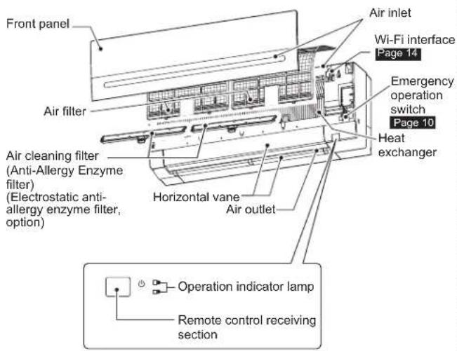
Indoor unit Remote controller
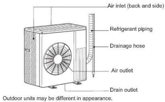
Outdoor unit
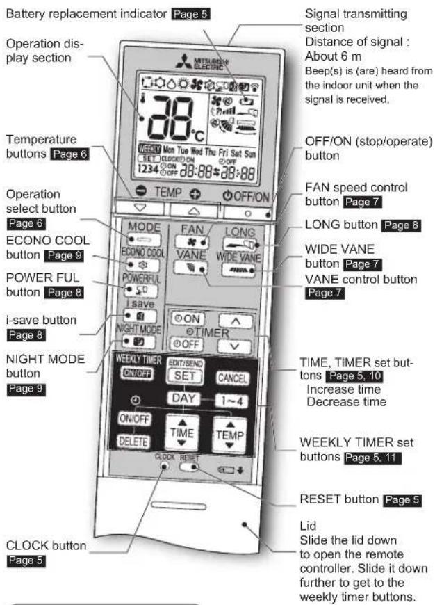
Remote controller holder
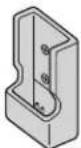
• Install the remote controller holder in a place where the signal can be received by the indoor unit.
- When the remote controller is not used, place it in this holder.
Only use the remote controller provided with the unit.
Do not use other remote controllers. If 2 or more indoor units are installed in proximity to one another, an indoor unit that is not intended to be operated may respond to the remote controller.
Before operation: Insert the power supply plug into the power turn the breaker on.
Installing the remote controller batteries
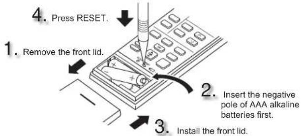
Note:
• Make sure the polarity of the batteries is correct.
- Do not use manganese batteries and leaking batteries. The remote controller could malfunction.
• Do not use rechargeable batteries.
- The battery replacement indicator lights up when the battery is running low. In about 7 days after the indicator starts lights up, the remote controller stops working.
- Replace all batteries with new ones of the same type.
- Batteries can be used for approximately 1 year. However, batteries with expired shelf lives last shorter.
- Press RESET gently using a thin instrument.
If the RESET button is not pressed, the remote controller may not operate correctly.
outlet and/or Setting current time
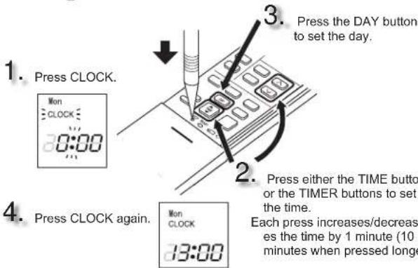
Note:
- Press CLOCK gently using a thin instrument.
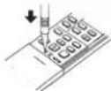
Note:
How to set remote controller exclusively for a particular indoor unit
A maximum of 4 indoor units with wireless remote controllers can be used in a room.
To operate the indoor units individually with each remote controller, assign a number to each remote controller according to the number of the indoor unit.
This setting can be set only when all the following conditions are met:
• The remote controller is powered OFF.
(1) Hold down 1\~4 button on the remote controller for 2 seconds to enter the pairing mode.
(2) Press 14 button again and assign a number to each remote controller. Each press of 14 button advances the number in the following order: 1 2 3 4 .
(3) Press SET/LEND button to complete the pairing setting.
After you turn the breaker ON, the remote controller that first sends a signal to an indoor unit will be regarded as the remote controller for the indoor unit. Once they are set, the indoor unit will only receive the signal from the assigned remote controller afterwards.
Press OFF/ON to start the operation.
2
Press MODE to select operation mode. Each press changes mode in the following order:

3
Press ☐ or to set the temperature. Each press raises or lowers the temperature by 1°C.

Press OFF/ON to stop the operation.
AUTO mode (Auto change over)
The unit selects the operation mode according to the difference between the room temperature and the set temperature. During AUTO mode, the changes mode (COOL↔HEAT) when the room temperature is about 2°C away from the set temperature for more than 15 minutes.
Note:
Auto Mode is not recommended if this indoor unit is connected to a MXZ type outdoor unit. When several indoor units are operated simultaneously, the unit may not be able to switch operation mode between COOL HEAT. In this case, the indoor unit becomes standby mode (Refer to table of Operation indicator lamp).

COOL mode
Enjoy cool air at your desired temperature.
Note:
Do not operate COOL mode at very low outside temperatures (less than -10°C). Water condensed in the unit may drip and wet or damage furniture, etc.
DRY mode
Dehumidify your room. The room may be cooled slightly. Temperature cannot be set during DRY mode.
HEAT mode
Enjoy warm air at your desired temperature.
FAN mode
Circulate the air in your room.
Note:
After COOL/DRY mode operation, it is recommended to FAN mode to dry inside the indoor unit.

Note:
Multi system operation
Two or more indoor units can be operated by one outdoor unit. When several indoor units are operated simultaneously, cooling/dry/fan and heating operations cannot be done at the same time. When COOL/DRY/FAN is selected with one unit and HEAT with another or vice versa, the unit selected last goes into standby mode.
Operation indicator lamp
The operation indicator lamp shows the operation state of the unit.
| Indication | Operation state Room temperature | |
| The unit is operating to reach the set temperature | About 2°C or more away from set temperature | |
| The room temperature is approaching the set temperature | About 1 to 2°C from set temperature | |
| Demand Response mode Page 12 |

Lit Blinking
- Not lit
unit
and
FAN SPEED AND AIRFLOW DIRECTION ADJUSTMENT
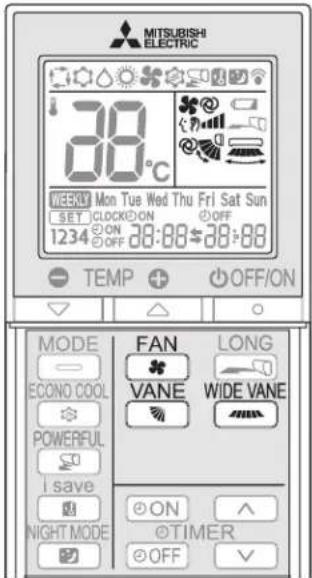
Fan speed
FAN
Press ☐ to select fan speed. Each press changes fan speed in the following order:

- Two short beeps are heard from the indoor unit when set to AUTO.
- Use higher fan speed to cool/heat the room quicker. It is recommended to lower the fan speed once the room is cool/warm.
- Use lower fan speed for quiet operation.
Note:
Multi system operation
When several indoor units are operated simultaneously by one outdoor unit for heating operation, the temperature of the airflow may be low. In this case, it is recommended to set the fan speed to AUTO.
Up-down Airflow direction
VANE
Press to select airflow direction. Each press changes airflow direction in the following order:


(AUTO) ......The vane is set to the most efficient airflow direction. COOL/DRY/FAN: horizontal position. HEAT: position (4).

(Manual) .....For efficient air conditioning, select the upper position for COOL/DRY, and the lower position for HEAT. If the lower position is selected during COOL/DRY, the vane automatically moves to the upward position after 0.5 to 1 hour to prevent any condensation from dripping.

(Swing) ......The vane moves up and down intermittently.
- Two short beeps are heard from the indoor unit when set to AUTO.
- Always use the remote controller when changing the direction of airflow. Moving the horizontal vanes with your hands causes them to malfunction.
- When the breaker is turned on, the horizontal vanes' position will be reset in about a minute, then the operation will start. The same is true in the emergency cooling operation.
- When the horizontal vanes seem to be in an abnormal position, see page 13.
Left-right Airflow direction
WIDE VANE
Press 📄 to select airflow direction. Each press changes airflow direction in the following order:

flowchart
graph LR
    A["Start"] --> B["Step 1"]
    B --> C["Step 2"]
    C --> D["Step 3"]
    D --> E["Step 4"]
    E --> F["Step 5"]
    F --> G["Step 6"]
    G --> H["(SWING)"]
LONG OPERATION
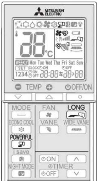
Press LONG to start LONG operation.
- Fan speed increases and the horizontal vane moves to the position for LONG mode.
• Air reaches to longer distance.
Press LONG again to cancel LONG operation.
- LONG operation is cancelled when the OFF/ON, VANE, or COOL button is pressed.
POWERFUL OPERATION
Press POWERFUL during COOL or HEAT mode Page 6 to start POWERFUL operation.
Fan speed : Exclusive speed for POWERFUL mode
Horizontal vane : Set position, or downward airflow position AUTO setting
• Temperature cannot be set during POWERFUL operation.
Press ☐ again to cancel POWERFUL operation.
- POWERFUL operation also is cancelled automatically in utes, or when the OFF/ON, FAN, ECONO COOL, or i-save button is pressed.
I-SAVE OPERATION
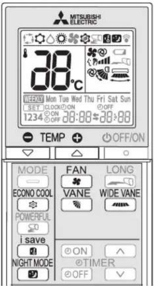
A simplified set back function enables to recall the preferred (preset) setting with a single push of the button. Press the button again and you can go back to the previous setting in an instance.
1
i save
Press during COOL, ECONO COOL, NIGHT MODE, or HEAT mode to select i-save mode.
2
Set the temperature, fan speed, and airflow direction.
• The same setting is selected from the next time by simply pre

- Two settings can be saved. (One for COOL/ECONO COOL, one for HEAT)
- Select the appropriate temperature, fan speed, and airflow direction according to your room.
- Normally, the minimum temperature setting in HEAT mode is 16°C. However, during i-save operation only, the minimum temperature setting is 10°C.
-
i save
Press again to cancel i-save operation.
during • i-save operation also is cancelled when the MODE button is pressed.
Note:
Example of use:
-
Low energy mode Set the temperature 2^ C to 3^ C warmer in COOL and cooler in HEAT mode. This setting is suitable for unoccupied room, and while you are sleeping.
-
Saving frequently used settings Save your preferred setting for COOL/ECONO COOL and HEAT. This enables you to select your preferred setting with a single push of the button.
Swing airflow (change of airflow) makes you feel cooler than stationary airflow.
The set temperature and the airflow direction are automatically changed by the microprocessor. It is possible to perform cooling operation with keeping comfort. As a result energy can be saved.

Press ECONO COOL during COOL mode ECONO COOL operation.
ge 6 start
The unit performs swing operation vertically in various cycles according to the temperature airflow.

Press ECONO COOL again to cancel ECONO COOL operation.
- ECONO COOL operation is also cancelled when the VANE button is pressed.
NIGHT MODE changes the brightness of the operation indicato disables the beep sound and limits the noise level of the outdoor unit.
NIGHT MODE
Press ☑ during operation to activate NIGHT MODE.
• The operation indicator lamp dims.
- The beep sound will be disabled except that emitted when the operation is started or stopped.
- Noise level of the outdoor unit will be lower than that mention SPECIFICATIONS.
NIGHT MODE
Press 📋gain to cancel NIGHT MODE.
Note:
• The cooling/heating capacity may drop.
- Noise level of the outdoor unit may not change after start-up of the unit, during the protection operation, or depending on other operating conditions.
• The fan speed of the indoor unit will not change.
• The operation indicator lamp will be hard to be seen in a bright room.
- Noise level of the outdoor unit will not decrease during Multi system operation.
Press ☐ ON during operation to set the timer.
ON (ON timer): The unit turns ON at the set time.
OFF (OFF timer): The unit turns OFF at the set time.
* @ON blingsf
* Make sure that the current time and day are set correctly. Page 5
2
Press (Increase) and (Decrease) to set the time of timer.
Each press increases or decreases the set time by 10 minutes.
- Set the timer while ON or OFF linking.
3
Press ⏻ON or ⏻OFF again to cancel timer.
Note:
- ON and OFF timers can be set together. mark indicates the order of timer operations.
- If power failure occurs while ON/OFF timer is set, see page 10 "Auto restart function".
EMERGENCY OPERATION
When the remote controller cannot be used...
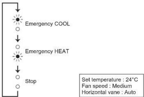
Emergency operation can be activated by pressing the emergency operation switch (E.O.SW) on the indoor unit.
Each time the E.O.SW is pressed, the operation changes in the following order:
Operation indicator lamp
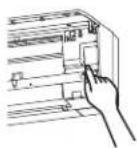
flowchart
graph TD
    A["Emergency COOL"] --> B["Emergency HEAT"]
    B --> C["Stop"]
Note:
- The first 30 minutes of operation is test run. Temperature control does not work, and fan speed is set to High.
- In the emergency heating operation, the fan speed gradually rises to blow out warm air.
- In the emergency cooling operation, the horizontal vanes' position will reset in about a minute, then the operation will start.
AUTO RESTART FUNCTION
If a power failure occurs or the main power is turned off during operation, "Auto restart function" automatically starts operation in the same mode as the one set with the remote controller just before the shutoff of the main power. When timer is set, timer setting is cancelled and the unit starts operation when power is resumed.
If you do not want to use this function, please consult the service representative because the setting of the unit needs to be changed.
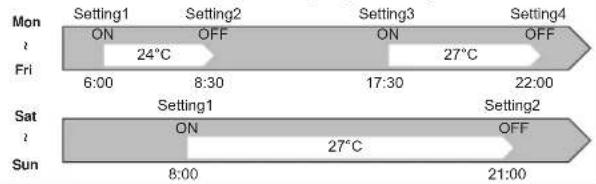
• A maximum of 4 ON or OFF timers can be set for individual days of the week.
• A maximum of 28 ON or OFF timers can be set for a week.
E.g.: Runs at 24°C from waking up to leaving home, and runs at 27°C from getting home to going to bed on weekdays.
Runs at 27°C from waking up late to going bed early on weekends.
Note:
The simple ON/OFF timer setting is available while the weekly timer is on. In this case, the ON/OFF timer has priority over the weekly timer; the weekly timer operation will start again after the simple ON/OFF timer is complete.
Setting the weekly timer
* Make sure that the current time and day are set correctly.
1
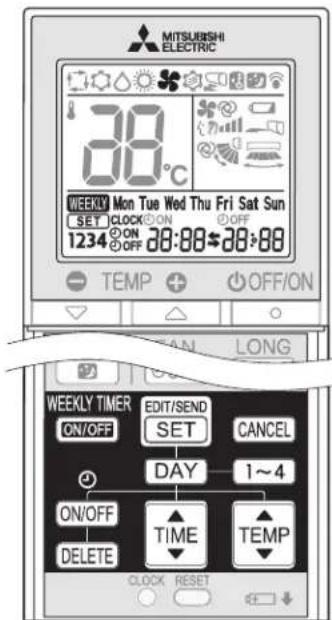
Press EDIT/SEND SET to enter the weekly timer setting mode.
2
Press DAY and 1\~4 to select setting day and number.
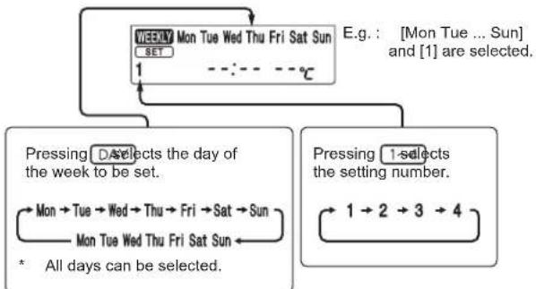
flowchart
graph TD
    A["WEEDLY Mon Tue Wed Thu Fri Sat Sun"] --> B["1"]
    B --> C["..."]
    C --> D["..."]
    D --> E["°C"]
    E --> F["E.g.: [Mon Tue ... Sun"] and["1"] are selected.]
    G["Pressing D selects the day of the week to be set."] --> H["Mon → Tue → Wed → Thu → Fri → Sat → Sun"]
    H --> I["Mon Tue Wed Thu Fri Sat Sun ←"]
    I --> J["* All days can be selected."]
    K["Pressing 1 selects the setting number."] --> L["1 → 2 → 3 → 4"]
En-11
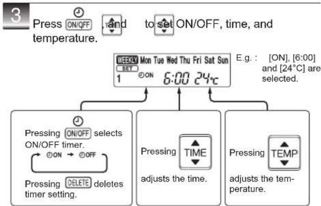
flowchart
graph TD
    A["Press ON/OFF"] --> B["To set ON/OFF, time, and temperature."]
    B --> C["Mon Tue Wed Thu Fri Sat Sun"]
    C --> D["1 ON 6:00 24°C"]
    D --> E["Pressing ON/OFF selects ON/OFF timer.<br>ON → OFF"]
    E --> F["Pressing DELETE deletes timer setting."]
    F --> G["Pressing TIME adjusts the time."]
    G --> H["Pressing TEMP adjusts the temperature."]
* Hold down the button to change the time quickly.
Press DA and to continue setting the timer for other days and/or numbers.
4 Press SBO complete and transmit the weekly timer setting. Mon CLOCK 13:00 * SET which was blinking goes out, and the current time will be displayed.
Note:
- Press SET to transmit the setting information of weekly timer to the indoor unit. Point the remote controller toward the indoor unit for 3 seconds.
- When setting the timer for more than one day of the week or one number,
/SEND does not have to be pressed per each setting. /SEND once after all the settings are complete. All the weekly timer settings will be saved. - Press SET/SEND to enter the weekly timer setting mode, and press and hold DELETE for 5 seconds to erase all weekly timer settings. Point the controller toward the indoor unit.
5 Press WEEKLY TIMER & NCT to turn the weekly timer ON. ( lights.)
* When the weekly timer is ON, the day of the week whose timer setting is complete, will light.
WEEKLY PRESS MAIN to turn the weekly timer OFF. (WEEKLY goes out.)
Note: The saved settings will not be cleared when the weekly timer is turned OFF.
Checking weekly timer setting
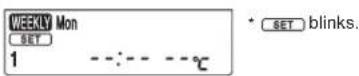
1 Press SETTENDO to enter the weekly timer setting mode. * tlinks.
2 Press DAY to view the setting of the particular day or number.
Press CANCE exit the weekly timer setting.
Note: When all days of the week are selected to view the settings and a different setting is included among them, --:-- --:°C will be displayed.
DEMAND RESPONSE AND INDOOR UNIT OPERATION(DEMAND TYPE ONLY)
Demand response
This unit has demand response capability which is compliant with AS/NZS 4755.3.1.
To activate this function, you need to make a contract with remote agents such as electric supply company, then this unit should be connected to Demand response enabling devise (DRED). For further information, consult your dealer.
Demand response represents the automated alteration of an electrical product's normal mode of operation in response to an initiating signal originating from or defined by a remote agent.
This unit supports 3 Demand Response Modes (DRMs).
| DRM Description of operation in this mode |  Not-lit Not-lit | |
| DRM 1 | Compressor offThe air conditioner does not perform cooling or heating operation during the demand response event. | Upper lamp is lit.electrical energyLower lamp blinks.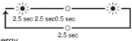 electrical energy electrical energy |
| DRM 2 | The air conditioner continues to perform cooling or heating operation during the demand response event, but the electrical energy consumed by the air conditioner in a half hour period is not more than 50% of the total that would be consumed if operating at the rated capacity in a half hour period. | |
| DRM 3 | The air conditioner continues to perform cooling or heating operation during the demand response event, but the electrical energy consumed by the air conditioner in a half hour period is not more than 75% of the total that would be consumed if operating at the rated capacity in a half hour period. | |
Note:
- DRM is automatically activated or released according to the signals from DRED.
DRM cannot be invalidated or changed manually. - You might feel this unit does not sufficiently perform cooling or heating operation during DRM.
- Operation settings can be changed as usual with the remote controller during DRM.
However, you might not feel cool or warm enough as DRM is prioritized.
CLEANING
Instructions:
- Switch off the power supply or turn off the breaker before cleaning.
- Be careful not to touch the metal parts with your hands.
- Do not use benzine, thinner, polishing powder, or insecticide.
• Use only diluted mild detergents.
• Do not use a scrubbing brush, a hard sponge, or the like.
• Do not soak or rinse the horizontal vane.
• Do not use water hotter than 50°C.
- Do not expose parts to direct sunlight, heat, or fire to dry.
• Do not apply excessive force on the fan as it may cause cracks or breakage.
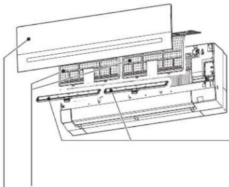
natural_image
Technical line drawing of an air conditioning unit with internal components and ventilation duct (no text or labels)Air filter (Air purifying filter)
Clean every 2 weeks
- Remove dirt by a vacuum cleaner, or rinse with water.
• After washing with water, dry it well in shade.
Front panel
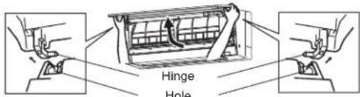
- Lift the front panel until a "click" is heard.
- Hold the hinges and pull to remove as shown in the illustration above.
• Wipe with a soft dry cloth or rinse it with water.
• Do not soak it in water for more than two hours.
• Dry it well in shade before installing it. - Install the front panel by following the removal procedure in reverse. Close the front panel securely and press the positions indicated by the arrows.
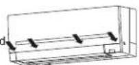
Air cleaning filter (Anti-Allergy Enzyme filter)
Every 3 months:
- Remove dirt by a vacuum cleaner.
When dirt cannot be removed by vacuum cleaning:
- Soak the filter and its frame in lukewarm water before rinsing it.
• After washing, dry it well in shade. Install all tabs of the air filter.
Every year:
- Replace it with a new air cleaning filter for best performance.
• Parts Number MAC-2350F1-E
(Electrostatic anti-allergy enzyme filter, option)
Every 3 months:
- Remove dirt by a vacuum cleaner.
When dirt cannot be removed by vacuum cleaning:
- Soak the filter and its frame in lukewarm water before rinsing it.
• After washing, dry it well in shade.
Every year:
- Replace it with a new air cleaning filter for best performance.
• Parts Number MAC-2310FT-E
Filter guide
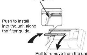
Important
- Clean the filters regularly for best performance and reduce power consumption.
- Dirty filters cause condensation in the air conditioner which will contribute to the growth of fungi such as mold. It is therefore recommended to clean air filters every 2 weeks.
Wi-Fi INTERFACE SETTING UP (VGK TYPE ONLY)
This Wi-Fi interface, communicates the status information and controls the commands from the server by connecting to the indoor unit.
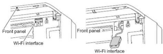
Wi-Fi interface introduction
| No | Item | Description |
| 1 | MODE Button | Selects modes. |
| 2 | RESET Button | Resets the system and ALL settings. |
| 3 | ERR LED (Orange) | Shows the network error state. |
| 4 | NET LED (Green) | Shows the network state. |
| 5 | MODE LED (Orange) | Shows the Access Point Mode state. |
| 6 | UNIT LED (Green) | Shows the indoor unit state. |
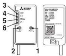
(1) MODE Button
WPS-Push
- Hold down the MODE Button for 2 seconds to start WPS-Push Pairing.
- When WPS-Push is enabled on the Wi-Fi interface, the MODE LED starts flashing orange (every second) and the pairing can be completed by enabling WPS-Push on the Router.
Access Point Mode
- Hold down the MODE Button for 7 seconds to start Access Point Mode.
- When Access Point Mode is enabled on the Wi-Fi interface, the MODE LED starts flashing orange (every 5 seconds).
- To cancel Access Point Mode, hold down the MODE Button for 7 seconds again and ensure that the MODE LED is no longer flashing.
WPS-PIN
- Hold down the MODE Button for 15 seconds to start WPS-PIN Pairing.
- When WPS-PIN is enabled on the Wi-Fi interface, MODE LED starts flashing orange (every 0.5 seconds) and the pairing can be completed by enabling WPS-PIN on the Router.
- Before using WPS-PIN, the PIN code of the Wi-Fi interface needs to be set on the Router.
(2) RESET Button
- Hold down the RESET Button for 2 seconds to reboot the system.
- Hold down the RESET Button for 15 seconds to initialise the Wi-Fi interface to the factory default.
Note:
When the Wi-Fi interface is reset to the factory default, ALL the configuration information will be lost. Take great care in implementing this operation.
Information for users
The following steps explain how to connect the Wi-Fi interface to a Router.
KEY (LED LIGHTS): ☀ : ON ☐ : OFF ☀ : Flashing

Ensure the Wi-Fi interface is connected correctly as per the previous section, 'Connecting the Wi-Fi interface'. UNIT LED should be flashing green only.
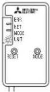

Download and install Wi-Fi Control App to your compatible Apple or Android smartphone/tablet (search term: Mitsubishi Wi-Fi Control).
THERE ARE TWO OPTIONS OF CONNECTING

Option 1 - Access Point Mode Pairing

Activate Access Point Mode on your Wi-Fi interface by using a small object to press and hold the MODE Button for 7 seconds.
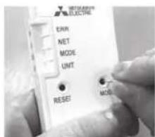

When Access Point Mode is enabled on the Wi-Fi interface, MODE LED starts flashing orange (every 5 seconds).
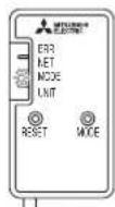

Check the label on the back of the interface for the SSID. Open the Wi-Fi networks screen on your smartphone/tablet and connect to the network with the same name as the SSID. The network password, labelled KEY, is just under the SSID on the interface.
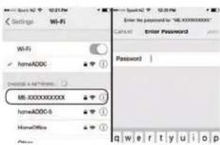
You will now be connected to this Wi-Fi interface

Open Wi-Fi Control App and follow the 'How to Setup' instructions in the 'Setup Wi-Fi interface' section.
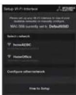
If the app does not go to this section, you are not connected to the Wi-Fi interface's Access Point; please start process again.
You can either select your available Wi-Fi Network, or manually configure a Wi-Fi Network.
Wi-Fi INTERFACE SETTING UP (VGK TYPE ONLY)
7
Once completed, the MAC and ID will be filled in 'Add new unit'. Select 'Add' and then control your heat pump via Wi-Fi.
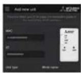
Option 2 - WPS-Push Pairing
- Please Note: The WPS and Router reset buttons may be similar on some Routers.
- Please exercise caution as resetting your Router will erase network configuration.
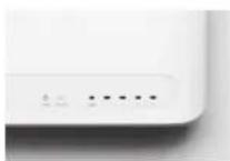
3
Check Wi-Fi and WPS are enabled on your Router. The connection procedure varies depending on your Router – refer to your Router's manual for more information.
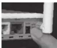
4
Activate WPS Mode on your Router. This will be enabled for a set period allowing approximately 2 minutes to complete the next step. To do so, please refer to your Router's manual.
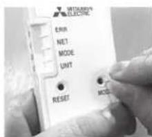
5
Activate WPS on your Wi-Fi interface by using a small object to press and hold the MODE Button for 2 seconds.
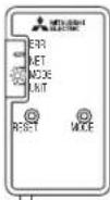
6
When WPS-Push is enabled on the Wi-Fi interface, MODE LED starts flashing orange (every second).
7
When pairing process is completed on the Wi-Fi interface, the NET LED lights up solid green for 5 seconds.
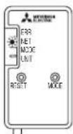
8
If ERR LED lights up orange for 5 seconds at any stage, there may be a problem; please start process again.
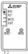
9
Open Wi-Fi Control App. Enter MAC and ID into 'Add new unit' and select 'Add'.
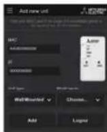
10
Once completed, control your heat pump via Wi-Fi.
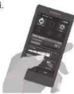
LED Pattern
:ON
:OFF
: Flashing
| • Software initialising | ||||
| Description | ERR(Orange) | NET(Green) | MODE(Orange) | UNIT(Green) |
| Firmware updating | ○ | ★ | ★ | ○ |
| Firmware downloading | ○ | ☆(everysecond) | ☆(everysecond) | ○ |
| Reset to the factory default | ○ | ○ | ★ | ★ |
| • Wireless setting | ||||
| Description | ERR(Orange) | NET(Green) | MODE(Orange) | UNIT(Green) |
| Access Point Mode activated | ○ | ○ | ☆(every 5 sec) | ☆(every 5 sec) |
| WPS-PUSH Mode activated | ○ | ○ | ☆(every second) | ○ |
| WPS-PIN Mode activated | ○ | ○ | ☆(every 0.5 sec) | ○ |
| Pairing process via WPS completed | ○ | ★(5 sec) | ○ | ○ |
| Pairing process via WPS failed | ★(5 sec) | ○ | ○ | ○ |
| • Connection to server in progress | ||||
| Description | ERR(Orange) | NET(Green) | MODE(Orange) | UNIT(Green) |
| Communicating with server, and starting up indoor unit communication | ○ | ☆(*1) | ○ | ★ |
| Communicating with server, and communicating with indoor unit | ○ | ☆(*1) | ○ | ☆(every 5 sec) |
| • Normal operation | ||||
| Description | ERR(Orange) | NET(Green) | MODE(Orange) | UNIT(Green) |
| Communicating with server, and communicating with indoor unit | ○ | ☆(every 5 sec) | ○ | ☆(every 5 sec) |
(*1) Details of flash pattern
• Every 0.5 sec: Searching for server.
• Every second: Registering the information of the Wi-Fi interface to server.
Wi-Fi INTERFACE SETTING UP (VGK TYPE ONLY)
Troubleshooting
:ON
☀ : Flashing : OFF
| Description | ERR (Orange) | NET (Green) | MODE (Orange) | UNIT (Green) |
| Connection to server established, and connection to indoor unit failed | ○ | ☀ | ○ | ○ |
| Connection to Router failed, and connection to indoor unit established | ○ | ○ (*3) | ○ | ☀ |
| Connection to Router failed, and starting up indoor unit connection | ○ | ○ (*3) | ○ | ★ |
| Connection to Router failed, and connection to indoor unit failed | ○ | ○ (*3) | ○ | ○ |
| Connection to server failed, and connection to indoor unit established | ☀ (*2) | ☀ | ○ | ☀ |
| Connection to server failed, and starting up indoor unit connection | ☀ (*2) | ☀ | ○ | ★ |
| Connection to server failed, and connection to indoor unit failed | ☀ (*2) | ☀ | ○ | ○ |
(\*2) Details of flash pattern
- Every 0.5 sec: IP address setting is invalid. Check DHCP Server, or check IP address settings of the Wi-Fi interface. If both settings are correct but still the problem persists, push RESET Button for more than 15 seconds to retry the pairing.
- Every second: DNS setting is invalid. Check DNS Settings of: or check DNS address settings of the Wi-Fi interface. If both settings are correct but still the problem persists, push RESET Button for more than 15 seconds to retry the pairing.
- Twice every 5 sec: Not connected to server. Check if the Router is connected to the internet.
- Once every 5 sec: Not communicating with server properly. Button for 2 seconds.
(\*3) Details when NET LED is OFF
The Wi-Fi interface failed to connect to the Router. Check the following, and pair the Wi-Fi interface.
• Make sure that the communication distance is not too far between the Wi-Fi interface and the Router.
• Make sure 2.4GHz is enabled on dual band Routers.
• Make sure that the Router uses WPA2-PSK(AES) encryption.
- Make sure that the number of connected devices to the exceed the limit.
• Make sure that WPS is working on the Router.
• Make sure that the Router is compatible with the Wi-Fi interface.
• If Static IP has been set - make sure it is correct as per Router network settings.
If a problem regarding connecting your Router and the Wi-Fi interface persists, please contact your local Mitsubishi Electric office, as listed on the back of this guide. A list of compatible Routers is also available.
Note:
- Ensure that the Router supports the WPA2-AES encryption setting before starting the Wi-Fi interface setup.
- The End user should read and accept the terms and conditions of the Wi-Fi service before using this Wi-Fi interface.
- To complete connection of this Wi-Fi interface to the Wi-Fi service, the Router may be required.
- This Wi-Fi interface will not commence transmission of any operational data from the system until the End user registers and accepts the terms and conditions of the Wi-Fi service.
- This Wi-Fi interface should not be installed and connected to any Mitsubishi Electric system which is to provide application critical cooling or heating.
- Please write down the information regarding the Wi-Fi interface setting on the last page of this manual, when you set up this Wi-Fi interface.
- At the time of relocation or disposal, reset the Wi-Fi interface to the facto default.
Mitsubishi Electric's Wi-Fi interface is designed for communication to Mitsubishi Electric's Wi-Fi service. Third party Wi-Fi interfaces cannot connect to Mitsubishi Electric's Wi-Fi service. Mitsubishi Electric is not responsible for any (i) underperformance of a system or any product; (ii) system or product fault; or (iii) loss or damage to any system or product; which is caused by or arises from connection to and/or use of any third party Wi-Fi interface or any third party Wi-Fi service with Mitsubishi Electric equipment.
For the latest information regarding Wi-Fi Control:
New Zealand based enquiries please visit: www.mitsubishi-electric.co.nz/wifi Australian based enquiries please visit: www.mitsubishielectric.com.au/wifi
the Router,
Mitsubishi Electric Wi-Fi Heat Pump Control
Register Your Heat Pump(s)
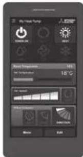
Pushk Res for choosing a Mitsubishi Electric Heat Pump with Wi-Fi Control. Once your Wi-Fi interface is installed, either download the app (search term: Mitsubishi Wi-Fi Control) or visit our website to register your heat pump(s).

Download on the App Store

GET IT ON Google Play
Once registered you will be able to control your heat pump with your smartphone, tablet or online account using an internet connection.
(For a list of compatible devices, please visit the
Route Mitsubishi Electric website).
User Manual
A copy of the user manual, terms & conditions and privacy policy can be downloaded at any time from the Mitsubishi Electric website.
Mitsubishi Electric New Zealand
www.mitsubishi-electric.co.nz/wifi Phone: 0800 639 434
Mitsubishi Electric Australia
www.mitsubishielectric.com.au/wifi
Phone: 1300 728 119
*Apple and the Apple logo are trademarks of Apple Inc., registered in the U.S. and other countries. App Store is a service mark of Apple Inc., registered in the U.S. and other countries.
*Google Play and the Google Play logo are trademarks of Google Inc.
WHEN YOU THINK THAT TROUBLE HAS OCCURRED
Even if these items are checked, when the unit does not recover from the trouble, stop using the air conditioner and consult your dealer.
| Symptom Explanation & Check points | |
| Indoor Unit | |
| The unit cannot be operated. | Is the breaker turned on?Is the power supply plug connected?Is the ON timer set Page 1 |
| The horizontal vane does not move. | Are the horizontal vane and the vertical vane installed correctly?Is the fan guard deformed?When the breaker is turned on, the horizontal vanes' position will be reset in about a minute. After the reset has completed, the normal horizontal vanes' operation resumes. The same is true in the emergency cooling operation. |
| The unit cannot be operated for about 3 minutes when restarted. | This protects the unit according to instructions from the microprocessor. Please wait. |
| Mist is discharged from the air outlet of the indoor unit. | The cool air from the unit rapidly cools moisture in the air inside the room, and it turns into mist. |
| The swing operation of the HORIZ- ZONTAL VANE is suspended for a while, then restarted. | This is for the swing operation of the HORIZ- TAL VANE to be performed normally. |
| When SWING is selected in COOL/DRY/FAN mode, the lower horizontal vane does not move. | It is normal that the lower horizontal vane does not move when SWING is selected in COOL/ DRY/FAN mode. |
| The airflow direction changes during operation.The direction of the horizontal vane cannot be adjusted with the remote controller. | When the unit is operated in CO mode, if the operation continues with air blowing down for 0.5 to 1 hour, the direction of the airflow is automatically set to upward position to prevent water from condensing and dripping.In the heating operation, if theperature is too low or when defrosting is being done, the horizontal vane is automatically set to horizontal position. |
| The operation stops for about 10 minutes in the heating operation. | Outdoor unit is in defrost.Since this is completed in max. 10 please wait. (When the outside temperature too low and humidity is too high, frost is formed.) |
| The unit starts operation by itself when the main power is turned on, but hasn't received sign from the remote controller. | These models are equipped with restart function. When the main p turned off without stopping the unit remote controller and is turned on a unit starts operation automatically in the same mode as the one set with the remote control- ler just before the shutoff of the main Refer to "Auto restart function". Page 10 |
| The two horizontal vanes touch each other. The horizontal vanes are in an abnormal posi- tion. The horizontal vanes do not return to the correct "close position". | Perform one of the following:Turn off and on the breaker. Make sure the hori- zonal vanes move to the correct "close position"Start and stop the emergency cooling operation and make sure the horizontal vanes move to the correct "close position". |
| In COOL/DRY mode, when room temperature reaches the set temperature, the outdoor unit stops, then the indoor operates at low speed. | When the room temperature deviates from the nea set temperature, the indoor fan starts running according to the settings on the remote control- leunit |
| The indoor unit discolors over time. | Although plastic turns yellow due to the influenc of some factors such as ultraviolet temperature, this has no effect on the product functions. |
| The operation indicator lamp is dim. The unit does not beep. | Is the NIGHT mode set Page |
| Multi system | |
| The indoor unit which is not operating becomes warm and a sound, similar to water flowing, is heard from the unit. | A small amount of refrigerant continues to flow into the indoor unit even though it is not operat-ing. |
| When heating operation is selected, operation does not start right away. | When operation is started during defrosting of outdoor unit is done, it takes a few minutes (max 10 minutes) to blow out warm air. |
| Outdoor Unit | |
| The fan of the outdoor unit does not rotate even though the com- pressor is running. Even if the fan starts to rotate, it stops soon. | When the outside temperature is cooling operation, the fan operates intermittently to maintain sufficient cooling capacity. |
| Water leaks from the outdoor unit. | During COOL and DRY operations, pipe or pip connecting sections are cooled and this causes water to condense.In the heating operation, water condensed on the heat exchanger drips down.In the heating operation, the defrosting operation makes ice forming on the outdoor unit melt and drip down. |
| White smoke is discharged from the outdoor unit. | In the heating operation, vapor generated by the defrosting operation looks like white smoke. |
| Symptom Explanation & Check points | |
| Remote controller | |
| The display on the remote controller does not appear or it is dim. The indoor unit does not respond to the remote control signal. | Are the batteries exhaustedPageIs the polarity (+, -) of the batteries correct?Page 5Are any buttons on the remote controller of other electric appliances being pressed? |
| Does not cool or heat | |
| The room cannot be cooled or heated sufficiently. | Is the temperature setting appropriate?Page 6Is the fan setting appropriate? Please change fan speed to High or Super High.Page 7Are the filters cleanPage 1Is the fan or heat exchanger of the indoor unit clean?Page 13Are there any obstacles blocking the air inlet or outlet of the indoor or outdoor unit?Is a window or door open?It may take a certain time to reach the setting temperature or may not reach that depending on the size of the room, the ambient temperature, and the like.Is the NIGHT mode setPage |
| The room cannot be cooled sufficiently. | When a ventilation fan or a gas cooker is used in a room, the cooling load increases, resulting in an insufficient cooling effect.When the outside temperature is high, the cooling effect may not be sufficient. |
| The room cannot be heated sufficiently. | When the outside temperature is low, the heating effect may not be sufficient. |
| Air does not blow out soon in the heating operation. | Please wait as the unit is preparing to blow out warm air. |
| Airflow | |
| The air from the indoor unit smells strange.utes. | Are the filters cleanPage 1Is the fan or heat exchanger of the indoor unit clean?Page 13The unit may suck in an odor adhering to the wall, carpet, furniture, cloth, etc. and blow it out with the air. |
| Sound | |
| Cracking sound is heard. is the | This sound is generated by the expansion/contraction of the front panel, etc. due to change in temperature. |
| Burbling" sound is heard. er. | This sound is heard when the outside air is absorbed from the drain hose by turning on the range hood or the ventilation fan, making water flowing in the drain hose to spout out.This sound is also heard when the outside air blows into the drain hose in case wind is strong. |
| Mechanical sound is heard from the indoor unit. | This is the switching sound in turning on/off the fan or the compressor. |
| The sound of water flowing is heard. | This is the sound of refrigerant or condensed water flowing in the unit. |
| Hissing sound is sometimes heard. | This is the sound when the flow inside the unit is changed. |
| Timer | |
| Weekly timer does not operate according to settings.and | Is the ON/OFF timer setPage 1Transmit the setting information of the weekly timer to the indoor unit again. When the information is successfully received, a long beep will sound from the indoor unit. If information fails to be received, 3 short beeps will be heard. Ensure information is successfully received.Page 11When a power failure occurs and the main power turns off, the indoor unit built-in clock will be incorrect. As a result, the weekly timer may not work normally.Be sure to place the remote controller where the signal can be received by the indoor unit.Page 5 |
| The unit starts/stops the operation by itself. | Is the weekly timer setPage 1 |
WHEN YOU THINK THAT TROUBLE HAS OCCURRED
In the following cases, stop using the air conditioner and consult your dealer.
- When water leaks or drips from the indoor unit.
• When the operation indicator lamp blinks. - When the breaker trips frequently.
- The remote control signal is not received in a room where an electronic ON/OFF type fluorescent lamp (inverter-type fluorescent lamp, etc.) is used.
• Operation of the air conditioner interferes with radio or TV reception. An amplifier may be required for the affected device. - When an abnormal sound is heard.
• When any refrigerant leakage is found.
WHEN THE AIR CONDITIONER IS NOT GOING TO BE USED FOR A LONG TIME
1
Operate by COOL mode with the highest temperature set or FAN mode for 3 to 4 hours. Page 6
• This dries the inside of the unit.
- Moisture in the air conditioner contributes to favorable conditions for growth of fungi, such as mold.
2
Press OFF/ON to stop the operation.
3
Turn off the breaker and/or disconnect the power supply plug.
4
Remove all batteries from the remote controller.
When using the air conditioner again:
1
Clean the air filter. Page 13
2
Check that the air inlet and outlet of the indoor and outdoor units are not blocked.
3
Check that the earth is connected correctly.
4
Refer to the "PREPARATION BEFORE OPERATION", and follow the instructions. Page 5
INSTALLATION PLACE AND ELECTRICAL WORK
Installation place
Avoid installing the air conditioner in the following places.
• Where there is much machine oil.
• Salty places such as the seaside
• Where sulfide gas is generated such as hot spring, sewage, waste water.
- Where oil is splashed or where the area is filled with oily smoke (such as cooking areas and factories, in which the properties of plastic could be changed and damaged).
• Where there is high-frequency or wireless equipment.
• Where the air from the outdoor unit air outlet is blocked.
- Where the operation sound or air from the outdoor unit bothers the house next door.
- The mounting height of indoor unit 1.8 m to 2.3 m is recommended. If it is impossible, please consult your dealer.
- Do not operate the air conditioner during interior construction and finishing work, or while waxing the floor. Before operating the air conditioner, ventilate the room well after such work is performed. Otherwise, it may cause volatile elements to adhere inside the air conditioner, resulting in water leakage or scattering of dew.
- Do not use the Wi-Fi interface nearby the medical electrical equipment or people who have a medical device such as a cardiac pacemaker or an implantable cardioverter-defibrillator.
It can cause an accident due to malfunctions of the medical equipment device.
- This equipment should be installed and operated with a minimum distance of 20 cm between the device and the user or bystanders.
- Do not use the Wi-Fi interface nearby other wireless devices, microwaves, cordless phones, or facsimiles.
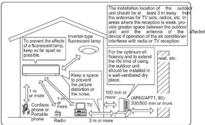
flowchart
graph TD
    A["Radio"] -->|1 m or more| B["Cordless phone or Portable phone"]
    B --> C["TV"]
    C --> D["3 m or more"]
    D --> E["Inverter-type fluorescent lamp"]
    E --> F["To prevent the effects of a fluorescent lamp, keep as far apart as possible."]
    E --> G["Keep a space to prevent the picture distortion or the noise."]
    G --> H["The installation location of the outdoor unit should be at least 3 m away from the antennas for TV sets, radios, etc. In areas where the reception is weak, provide greater space between the outdoor unit and the antenna of the device if operation of the air conditioner interferes with radio or TV reception."]
    E --> I["For the optimum efficiency and to extend the life time of using, the outdoor unit should be installed in a well-ventilated dry place."]
    I --> J["(AP60/AP71, 80)"]
    I --> K["200/500 mm or more"]
    J --> L["wall, etc."]
    K --> L
Electrical work
- Provide an exclusive circuit for the power supply of the air conditioner.
- Be sure to observe the breaker capacity.
If you have any questions, consult your dealer.
SPECIFICATIONS
Guaranteed operating range
| Indoor Outdoor | |||
| Cooling | Upper limit | 32°C DB23°C WB | 46°C DB— |
| Lower limit | 21°C DB15°C WB | -10°C DB— | |
| Heating | Upper limit | 27°C DB— | 24°C DB18°C WB |
| Lower limit | 20°C DB— | -15°C DB-16°C WB | |
DB : Dry Bulb
WB: Wet Bulb
Wi-Fi interface
| Model MAC-568IFB2-E | |
| Input Voltage DC12.7 V (from indoor unit) | |
| Power consumption MAX 2 W | |
| Size H×W×D (mm) 79×44×18.5 | |
| Weight (g) 60 (including cable) | |
| Transmitter power level (MAX) 17.5 dBm @IEEE 802.11b | |
| RF channel 1ch ~ 13ch (2412~2472 MHz) | |
| Radio protocol IEEE 802.11b/g/n (20) | |
| Encryption AES | |
| Authentication WPA2-PSK | |
| Software Version XX.00 | |
Wi-Fi interface setting information
| Indoor unit model name | |
| Indoor unit serial number | |
| Outdoor unit model name | |
| Outdoor unit serial number | |
| Wi-Fi interface MAC address (MAC) | |
| Wi-Fi interface serial number (ID) | |
| Wi-Fi interface PIN (PIN) | |
| Wi-Fi interface SSID (SSID) | |
| Wi-Fi interface KEY (KEY) | |
| System commissioning date | |
| Wi-Fi interface installation date |
Installer contact details
| Name | |
| Telephone number |
MEMO
MITSUBISHI ELECTRIC CORPORATION
- SPLIT-TYPE AIR CONDITIONERS
- INDOOR UNIT
- OPERATING INSTRUCTIONS
- CONTENTS
- Marks and their meanings
- Meanings of symbols used in this manual
- SAFETY PRECAUTIONS
- For installation
- WARNING
- CAUTION
- For Wi-Fi interface
- NAME OF EACH PART
- Remote controller holder
- Installing the remote controller batteries
- Note:
- outlet and/or Setting current time
- 2
- 3
- AUTO mode (Auto change over)
- COOL mode
- DRY mode
- HEAT mode
- FAN mode
- Multi system operation
- Operation indicator lamp
- FAN SPEED AND AIRFLOW DIRECTION ADJUSTMENT
- Fan speed
- FAN
- Up-down Airflow direction
- VANE
- Left-right Airflow direction
- WIDE VANE
- LONG OPERATION
- POWERFUL OPERATION
- I-SAVE OPERATION
- 1
- -
- NIGHT MODE
- EMERGENCY OPERATION
- When the remote controller cannot be used...
- AUTO RESTART FUNCTION
- Setting the weekly timer
- Checking weekly timer setting
- DEMAND RESPONSE AND INDOOR UNIT OPERATION(DEMAND TYPE ONLY)
- Demand response
- CLEANING
- Instructions:
- Air filter (Air purifying filter)
- Front panel
- Air cleaning filter (Anti-Allergy Enzyme filter)
- (Electrostatic anti-allergy enzyme filter, option)
- Important
- Wi-Fi INTERFACE SETTING UP (VGK TYPE ONLY)
- Wi-Fi interface introduction
- MODE Button
- WPS-Push
- Access Point Mode
- WPS-PIN
- RESET Button
- Information for users
- THERE ARE TWO OPTIONS OF CONNECTING
- Option 1 - Access Point Mode Pairing
- 7
- Option 2 - WPS-Push Pairing
- 4
- 5
- 6
- 8
- 9
- 10
- LED Pattern
- (\*2) Details of flash pattern
- (\*3) Details when NET LED is OFF
- Mitsubishi Electric Wi-Fi Heat Pump Control
- Register Your Heat Pump(s)
- Download on the App Store
- GET IT ON Google Play
- User Manual
- Mitsubishi Electric New Zealand
- Mitsubishi Electric Australia
- WHEN YOU THINK THAT TROUBLE HAS OCCURRED
- WHEN THE AIR CONDITIONER IS NOT GOING TO BE USED FOR A LONG TIME
- When using the air conditioner again:
- INSTALLATION PLACE AND ELECTRICAL WORK
- Installation place
- Electrical work
- SPECIFICATIONS
- MITSUBISHI ELECTRIC CORPORATION
Brand : MITSUBISHI
Model : MSZ-AP80VGD
Category : Air-conditioner