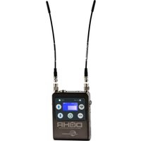
DCHR - Receiver Lectrosonics - Free user manual and instructions
Find the device manual for free DCHR Lectrosonics in PDF.


| Product Type | Wireless Receiver |
| Brand | Lectrosonics |
| Model | DCHR |
| Dimensions (H x W x D) | 1.7 x 8.3 x 6.3 inches (43 x 210 x 160 mm) |
| Weight | 1.5 lbs (0.68 kg) |
| Power Supply | DC 5V-18V, 500 mA max |
| Frequency Range | 470-608 MHz (UHF), tunable |
| RF Sensitivity | Better than 1 µV for 12 dB SINAD |
| Audio Output | Balanced XLR, unbalanced 1/4" jack |
| Antenna Input | Two BNC connectors for diversity |
| Diversity | True digital diversity |
| Display | Backlit LCD with frequency, audio level, RF level |
| Controls | Menu buttons, rotary encoder for frequency/settings |
| Mounting | Half-rack wide, includes rack ears |
| Operating Temperature | -10°C to 50°C |
| Included Accessories | AC power supply, BNC antennas, rack ears |
| Maintenance | Clean with dry cloth; no user-serviceable parts inside |
| Safety | Use only provided power supply; do not expose to moisture |
| Spare Parts / Repairability | Contact Lectrosonics service for replacement antennas, power supply, or internal repairs |
Frequently Asked Questions - DCHR Lectrosonics
User questions about DCHR Lectrosonics
0 question about this device. Answer the ones you know or ask your own.
Ask a new question about this device
Download the instructions for your Receiver in PDF format for free! Find your manual DCHR - Lectrosonics and take your electronic device back in hand. On this page are published all the documents necessary for the use of your device. DCHR by Lectrosonics.
USER MANUAL DCHR Lectrosonics
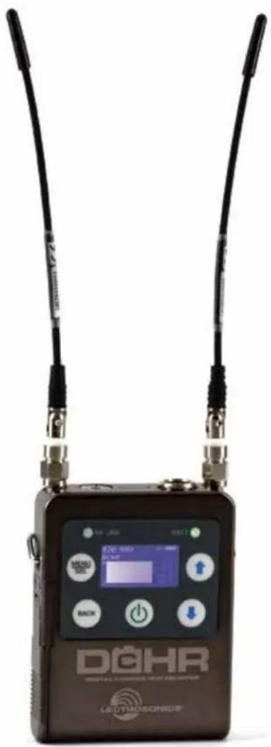
Digital Camera Hop Receiver


Fill in for your records:
Serial Number:
Purchase Date:
Quick Start Steps
1) Install receiver batteries and turn power on (pg. 5).
2) Set compatibility mode to match the transmitter (pg. 10).
3) Set or sync frequency to match transmitter (see page 10).
5) Set encryption key type and sync with transmitter (see page 11).
6) Choose analog or digital (AES3) output (see page 10).
7) Verify RF and audio signals are present.
CE

Table of Contents
Quick Start Steps....1
DCHR Digital 2-Channel Receiver....3
Smart Tuning (SmartTune™)....3
Encryption....3
RF Front-End with Tracking Filter....3
Panels and Features....4
Battery Status LED 5
RF Link LED....5
IR (infrared) Port 5
USB Port 5
Battery Compartment.... 5
Audio Jack and Pin Configuration 5
Keypad and LCD Interface....5
Installing Batteries 6
System Setup Procedure....6
DCHR LCD Menu Map 8
Menu Item Descriptions....10
RF Setup Menu 10
Audio Setup Menu....10
Sync/Encryption Menu....10
Tools/Settings....11
Accessories 13
Specifications 13
Service and Repair 14
Returning Units for Repair 14
NOTE: This equipment has been tested and found to comply with the limits for a Class B digital device, pursuant to part 15 of the FCC Rules. These limits are designed to provide reasonable protection against harmful interference in a residential installation. This equipment generates, uses and can radiate radio frequency energy and, if not installed and used in accordance with the instructions, my cause harmful interference to radio communications. However, there is no guarantee that interference will not occur in a particular installation. If this equipment does cause harmful interference to radio or television reception, which can be determined by turning the equipment off and on, the user is encouraged to try to correct the interference by one or more of the following measures:
• Reorient or relocate the receiving antenna.
- Increase the separation between the equipment and receiver.
- Connect the equipment into an outlet on a circuit different from that to which the receiver is connected.
- Consult the dealer or an experienced radio/TV technician for help.
DCHR Digital Stereo/Mono Receiver
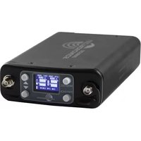
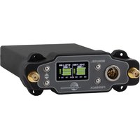
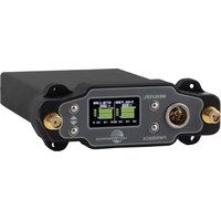
The DCHR Digital Receiver is engineered to work alongside the DCHT transmitter to form the Digital Camera Hop system. The receiver is also compatible with the M2T unencrypted and M2T-X encrypted digital stereo transmitters, and the D2 Series mono digital transmitters, including the DBu, DHu, and DPR. Designed to be camera mountable and battery powered, the receiver is ideal for location sound and televised sports, along with many other applications. The DCHR employs advanced antenna diversity switching during digital packet headers for seamless audio. The receiver tunes across a wide UHF frequency range.
The DCHR has a single audio output jack that can be configured as 2 independent balanced line level outputs or as a single 2 channel AES3 digital output.
The headphone monitor output is fed from a high-quality stereo amplifier with power available to drive even inefficient headphones or earphones to sufficient levels for noisy environments. An intuitive interface and high resolution LCD on the unit provide users with a quick read on the status of the system.
The DCHR also employs 2-way IR sync, so settings from the receiver can be sent to a transmitter. This way, frequency planning and coordination can be done quickly and confidently with on-site RF information.
Smart Tuning (SmartTune™)
A major problem facing wireless users is finding clear operating frequencies, especially in RF saturated environments. SmartTune ^™ overcomes this problem by automatically scanning all the frequencies available in the unit, and tuning to the frequency with the lowest RF interference, significantly reducing setup time.
Encryption
The DCHR provides AES 256-bit, CTR mode encryption. When transmitting audio, there are situations where privacy is essential, such as during professional sporting events. High entropy encryption keys are first created by the DCHR. The key is then synced with an encryption capable transmitter/receiver via the IR port. The audio will be encrypted and can only be decoded and heard if both the transmitter and the DCHR have the matching key. Four key management policies are available.
RF Front-End with Tracking Filter
A wide tuning range is helpful in finding clear frequencies for operation, however, it also allows a greater range of interfering signals to enter the receiver.
The UHF frequency band, where almost all wireless microphone systems operate, is heavily populated by high power TV transmissions. The TV signals are immensely more powerful than a wireless microphone or portable transmitter signal and will enter the receiver even when they are on significantly different frequencies than the wireless system. This powerful energy appears as noise to the receiver, and has the same effect as the noise that occurs with extreme operating range of the wireless system (noise bursts and dropouts). To alleviate this interference, high-quality front-end filters are needed in the receiver to suppress RF energy below and above the operating frequency.
The DCHR receiver employs a selective frequency, tracking filter in the front-end section (the first circuit stage following the antenna). As the operating frequency is changed, the filters re-tune into six different "zones" depending on the selected carrier frequency.

In the front-end circuitry, a tuned filter is followed by an amplifier and then another filter to provide the selectivity needed to suppress interference, yet provide a wide tuning range and retain the sensitivity needed for extended operating range.
Panels and Features

When on Main Screen, UP and DOWN buttons will adjust headphone volume.
Battery Status LED
When the battery status LED on the keypad glows green the batteries are good. The color changes to red at a midpoint during the runtime. When the LED begins to blink red, only a few minutes remain.
The exact point at which the LED turns red will vary with battery brand and condition, temperature and power consumption. The LED is intended to simply catch your attention, not to be an exact indicator of remaining time. The proper battery type setting in the menu will increase accuracy.
A weak battery will sometimes cause the LED to glow green immediately after the transmitter is turned on, but it will soon discharge to the point where the LED will turn red or the unit will turn off completely.
RF Link LED
When a valid RF signal from a transmitter is received, this LED will light up blue.
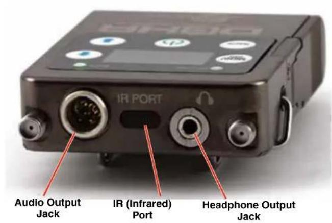
IR (infrared) Port
Settings, including frequency, name, compatibility mode, etc. can be transferred between receiver and transmitter.
Outputs
Headphone Monitor
A recessed, high duty cycle 3.5 mm stereo jack is provided for standard headphones and earphones.
Audio Jack (TA5M mini XLR):
- AES3
- Analog Line Out
The 5-pin input jack accommodates two discrete channels at microphone or line levels. The input connections are configured as follows:
| ANALOG DIGITAL | ||
| Pin 1 CH 1 | Shield/Gnd AES GND | |
| Pin 2 CH 1 | + AES CH 1 | |
| Pin 3 CH 1 | - AES CH 2 | |
| Pin 4 CH 2 | + ---- | |
| Pin 5 CH 2 | - ---- |

TA5FLX connector viewed from outside
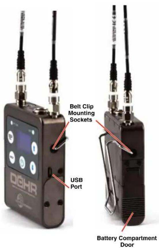
USB Port
Firmware updates via Wireless Designer software are made easy with the USB port on the side panel.
Battery Compartment
Two AA batteries are installed as marked on the rear panel of the receiver. The battery door is hinged and remains attached to the housing.
Keypad and LCD Interface

MENU/SEL Button
Pressing this button enters the menu and selects menu items to enter the setup screens.
BACK Button
Pressing this button returns to the previous menu or screen.
POWER Button
Pressing this button turns the unit on or off.
Arrow Buttons
Used to navigate the menus. When on Main Screen, UP Button will turn LEDs on and DOWN Button will turn LEDs off.
Installing Batteries
Power is provided by two AA batteries. The batteries are connected in series by a plate in the battery door. It is suggested that you use lithium or high capacity NiMH rechargeable batteries.

Polarity is marked on the rear panel.

natural_image
Close-up of a black electrical connector with two batteries and wires, no visible text or symbolsPolarity markings
System Setup Procedure
Step 1) Install Batteries and Turn Power On
Install the batteries according to the diagram marked on the back of the housing. The battery door makes a connection between the two batteries. It is suggested that you use lithium or high capacity NiMH rechargeable batteries.
Step 2) Set Compatibility Mode
Set compatibility mode according to the transmitter type, and make sure the transmitter compatibility mode is the same in the case where the transmitter offers different modes.
Step 3) Set or Sync Frequency to match Transmitter
In the transmitter, use "GET FREQ" or "GET ALL" in the menu to transfer frequency or other information via the IR ports. Hold the DCHR receiver IR port close to the front panel IR port on the transmitter and press GO on the transmitter.
Step 4) Set Encryption Key Type and Sync with Transmitter
Choose Encryption Key Type. If necessary, create key and use "SEND KEY" in the menu to transfer an encryption key via the IR ports. Hold the DCHR receiver IR port close to the front panel IR port on the transmitter and press GO on the transmitter.
Step 6) Choose Audio Output Function
Choose analog or digital (AES3) output as desired.
Step 7) Verify RF and Audio Signals are Present
Send an audio signal to the transmitter and the receiver audio meters should respond. Plug in headphones or earphones. (Be sure to start with the receiver volume settings at a low level!)
LCD Main Window

RF level
The triangle graphic corresponds to the scale on the left side of the display. The scale indicates the incoming signal strength in microvolts, from 1 uV at the bottom to 1,000 uV (1 millivolt) at the top.
NOTE: RF level will turn from white to green when the signal is acquired. This is a redundant indication of the blue RF Link LED.
Diversity activity
The two antenna icons will alternately light up depending on which one is receiving the stronger signal.
Battery life indicator
The battery life icon is an approximate indicator of the remaining battery life. For the most accurate indication, the user should select “Battery Type” in the menu and select Alkaline or Lithium.
Audio level
This bar graph indicates the level of the audio entering the transmitter. The "0" refers to the level reference, as chosen in the transmitter, i.e. either +4 dBu or -10 dBV.
Mixer mode
Indicates which mixer mode has been selected for the receiver. (See page 10.)
Navigating the Menus
From the Main Window, press MENU/SEL to enter the menu, then navigate with the UP and DOWN arrows to highlight the desired setup item. Press MENU/SEL to enter the setup screen for that item. Refer to the menu map on the following page.

DCHR LCD Menu Map

flowchart
RF setup and audio setup flowchart detailing RF tuning, frequency scanning, scan, and output settings with associated buttons and function descriptions.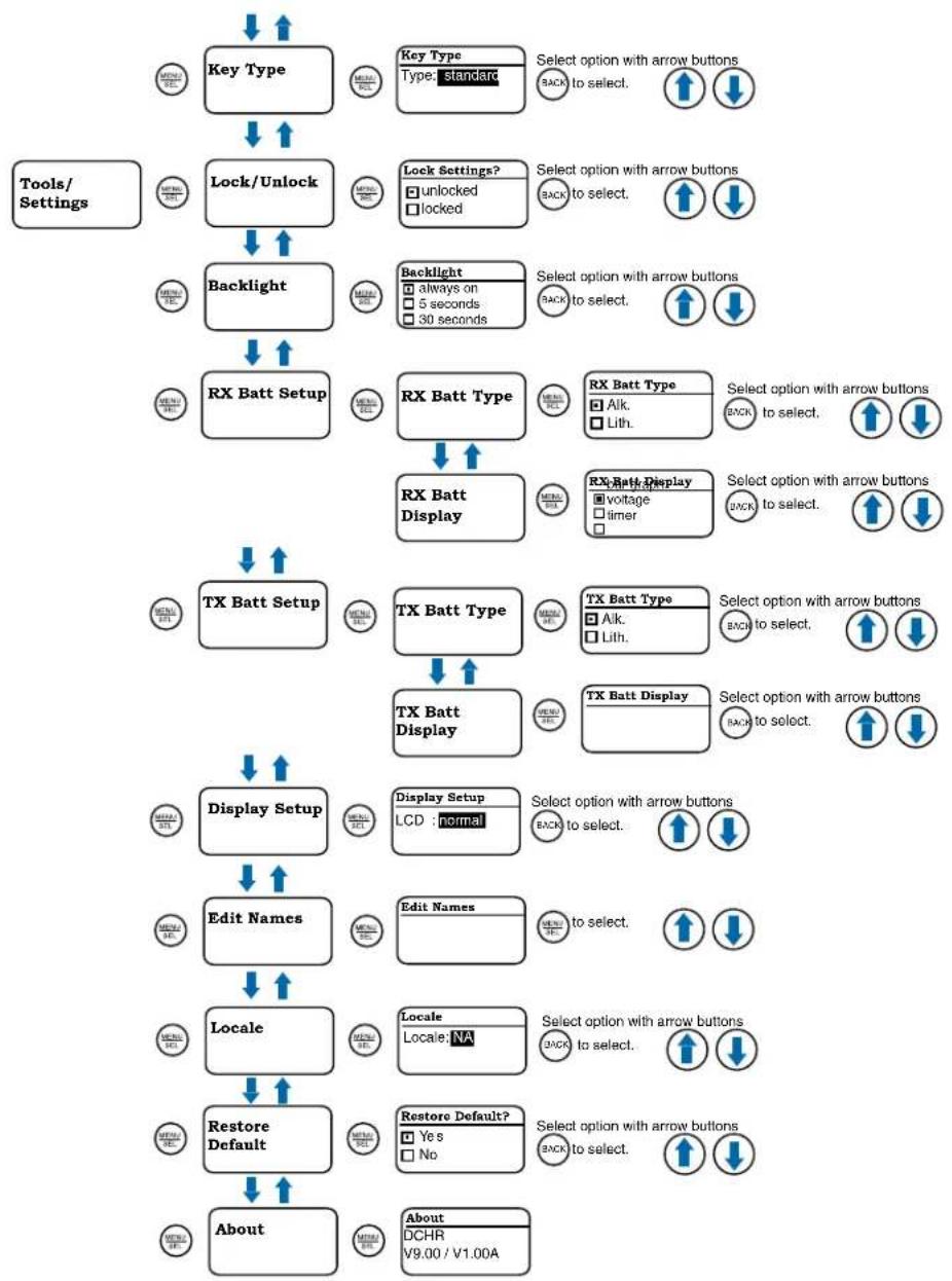
flowchart
graph TD
    A["Key Type"] --> B["Lock/Unlock"]
    B --> C["Backlight"]
    C --> D["RX Batt Setup"]
    D --> E["TX Batt Setup"]
    E --> F["Display Setup"]
    F --> G["Edit Names"]
    G --> H["Locale"]
    H --> I["Restore Default"]
    I --> J["About"]

    subgraph Tools/Settings
        A1["OK"] --> A2["OK"]
        A3["Lock"] --> A4["Lock Settings?"]
        A5["Backlight"] --> A6["Backlight"]
        A7["RX Batt Setup"] --> A8["RX Batt Type"]
        A9["TX Batt Setup"] --> A10["TX Batt Type"]
        A11["Display Setup"] --> A12["Display Setup"]
        A13["Edit Names"] --> A14["Edit Names"]
        A15["Locale"] --> A16["Locale"]
        A17["Restore Default"] --> A18["Restore Default"]
        A19["About"] --> A20["About"]

    end

    subgraph Lock Settings?
        B1["Unlocked"] --> B2["Locked"]
        B3["Locked"] --> B4["Locked"]
        B5["always on"] --> B6["5 seconds"]
        B7["30 seconds"] --> B8["30 seconds"]
        B9["RX Batt Type"] --> B10["RX Batt Type"]
        B11["RX Batt Type"] --> B12["RX Batt Type"]
        B13["RX Batt Type"] --> B14["RX Batt Type"]
        B15["RX Batt Type"] --> B16["RX Batt Type"]
        B17["RX Batt Type"] --> B18["RX Batt Type"]
        B19["RX Batt Type"] --> B20["RX Batt Type"]
        B21["RX Batt Type"] --> B22["RX Batt Type"]
        B23["RX Batt Type"] --> B24["RX Batt Type"]
        B25["RX Batt Type"] --> B26["RX Batt Type"]
        B27["RX Batt Type"] --> B28["RX Batt Type"]
        B29["RX Batt Type"] --> B30["RX Batt Type"]
        B31["RX Batt Type"] --> B32["RX Batt Type"]
        B33["RX Batt Type"] --> B34["RX Batt Type"]
        B35["RX Batt Type"] --> B36["RX Batt Type"]
        B37["RX Batt Type"] --> B38["RX Batt Type"]
        B39["RX Batt Type"] --> B40["RX Batt Type"]
        B41["RX Batt Type"] --> B42["RX Batt Type"]
        B43["RX Batt Type"] --> B44["RX Batt Type"]
        B45["RX Batt Type"] --> B46["RX Batt Type"]
        B47["RX Batt Type"] --> B48["RX Batt Type"]
        B49["RX Batt Type"] --> B50["RX Batt Type"]
        B51["RX Batt Type"] --> B52["RX Batt Type"]
        B53["RX Batt Type"] --> B54["RX Batt Type"]
        B55["RX Batt Type"] --> B56["RX Batt Type"]
        B57["RX Batt Type"] --> B58["RX Batt Type"]
        B59["RX Batt Type"] --> B60["RX Batt Type"]
        B61["RX Batt Type"] --> B62["RX Batt Type"]
        B63["RX Batt Type"] --> B64["RX Batt Type"]
        B65["RX Batt Type"] --> B66["RX Batt Type"]
        B67["RX Batt Type"] --> B68["RX Batt Type"]
        B69["RX Batt Type"] --> B70["RX Batt Type"]
    end

    subgraph Lock Settings?
        C1["Unlocked"] --> C2["Locked"]
        C3["Locked"] --> C4["Locked"]
    end

    subgraph Backlight
        D1["always on"] --> D2["5 seconds"]
        D3["30 seconds"] --> D4["30 seconds"]
    end

    subgraph Backlight
        E1["always on"] --> E2["5 seconds"]
        E3["30 seconds"] --> E4["30 seconds"]
    end

    subgraph RX Batt Setup
        F1["TX Batt Setup"] --> F2["TX Batt Setup"]
    end

    subgraph RX Batt Setup
        G1["TX Batt Setup"] --> G2["TX Batt Setup"]
    end

    subgraph TX Batt Setup
        H1["TX Batt Setup"] --> H2["TX Batt Setup"]
    end

    subgraph TX Batt Setup
        I1["TX Batt Setup"] --> I2["TX Batt Setup"]
    end

    subgraph Display Setup
        J1["LCD:normal"] --> J2["LCD:normal"]
    end

    subgraph Edit Names
        K1["Edit Names"] --> K2["Edit Names"]
    end

    subgraph Locale
        L1["Locale:NA"] --> L2["Locale:NA"]
    end

    subgraph Restore Default
        M1["Restoredefault?"] --> M2["Restored.default?"]
    end

    subgraph About
        N1["DCHR V9.00 / V1.00A"]
    end
Menu Item Descriptions
RF Setup Menu
SmartTune
SmartTune™ automates the discovery of a clear operating frequency. It does this by scanning all the available operating frequencies within the system's frequency range (in 100 kHz increments) and then selecting the frequency with the least amount of RF interference. When SmartTune™ is complete, it presents the IR Sync function for transferring the new setting to the transmitter. Pressing "Back" returns to the Main Window displaying the selected operating frequency.
RF Frequency
Allows manual selection of the operating frequency in MHz and kHz, tunable in 25 kHz steps.
You may also select a Frequency Group, which will limit the available frequency choices to those contained in the selected group (see Freq. Group Edit, below). Select Frequency Group NONE for normal tuning.
Frequency Scan
Use the scan function to identify a usable frequency. Allow the scan to continue until the entire band has been scanned.
Once a full cycle has been completed, press MENU/SELECT again to pause the scan.
Use the UP and DOWN arrows to roughly tune the receiver by moving the cursor to an open spot. Press MENU/SELECT to zoom in for fine tuning.
When a usable frequency has been selected, press the BACK button for the option to keep your newly selected frequency or to revert to where it was set before the scan.
Clear Scan
Erases scan results from memory.
Freq. Group Edit
User-defined Frequency Groups are edited here. Groups u, v, w and x may contain up to 32 user-selected frequencies. Use the UP and DOWN arrow buttons to select one of the four groups. Press the MENU/SELECT button to move the cursor to the frequency list for the group. Now, pressing the UP and DOWN arrow buttons moves the cursor in the list. To delete a selected frequency from the list, press MENU/SELECT + DOWN. To add a frequency to the list, press MENU/SELECT + UP. This opens the Frequency Selection screen. Use the UP and DOWN arrow buttons to select the desired frequency (in MHz and kHz). Press MENU/SELECT to advance from MHz to kHz. Press MENU/SELECT again to add the frequency. This opens a confirmation screen, where you can choose to add the frequency to the Group or cancel the operation.
In addition to the group NONE, this screen also allows selection of one of four user-defined pre-selected frequency groups (Groups u through x):
• Each press of the UP or DOWN button will step to the next stored frequency in the group.
Audio Setup Menu
Audio Level
Set audio output level with the level control. The TONE option is used to generate a 1 kHz test tone at the audio output.
Compat Modes
Multiple compatibility modes are available to match various transmitter types.
The following modes are available:
• D2: Encrypted digital wireless channel
• DUET: Standard (unencrypted) Duet channel
- DCHX: Encrypted digital camera hop channel, also compatible with M2T-X encrypted Duet channel
Output Type
The DCHR has a single audio output jack with two output type options:
- Analog: 2 balanced line level audio outputs, one for each audio channel sent by the DCHT. Uses 4 of the 5 pins in the connector, 2 pins for each analog audio channel plus ground.
- AES3: The AES3 digital signal contains both audio channels in a single signal. It uses 2 of the 5 pins in the connector plus ground.
Audio Polarity
Select normal or inverted polarity.
Sync/Encryption Menu
NOTE: You must position the transmitter's IR port directly in front of the DCHR IR port, as closely as possible, to guarantee a successful sync. A message will appear on the DCHR if the sync was successful or failed.
Send Frequency
Choose to send frequency via IR port to a transmitter.
Get Frequency
Choose to receive (get) frequency via IR port from a transmitter.
Send All
Choose to send settings via IR port to a transmitter.
Get All
Choose to receive (get) settings via IR port from a transmitter.
Key Type
Encryption Keys
The DCHR generates high entropy encryption keys to sync with encryption-capable transmitters and receivers. The user must select a key type and create a key in the DCHR, and then sync the key with a transmitter or another receiver (only in shared key mode).
Encryption Key Management
The DCHR has four options for encryption keys:
- Volatile: This one-time only key is the highest level of encryption security. The Volatile Key exists only as long as the power in both the DCHR and the encryption capable transmitter remains on during a single session. If an encryption capable transmitter is powered off, but the DCHR has remained turned on, the Volatile Key must be sent to the transmitter again. If the power is turned off on the DCHR, the entire session concludes and a new Volatile Key must be generated by the DCHR and sent to the transmitter via the IR port.
- Standard: Standard Keys are unique to the DCHR. The DCHR generates the Standard Key. The DCHR is the sole source of the Standard Key, and because of this, the DCHR may not receive (get) any Standard Keys.
- Shared: There are an unlimited number of shared keys available. Once generated by the DCHR and transferred to an encryption capable transmitter/receiver, the encryption key is available to be shared (synced) with other encryption capable transmitters/receivers via the IR port. When the DCHR is set to this key type, a menu item named SEND KEY is available to transfer the key to another device.
- Universal: This is the most convenient encryption option available. All encryption-capable Lectrosonics transmitters and receivers contain the Universal Key. The key does not have to be generated by the DCHR. Simply set a Lectrosonics encryption capable transmitter and the DCHR to Universal, and the encryption is in place. This allows for convenient encryption amongst multiple transmitters and receivers, but not as secure as creating a unique key.
NOTE: When the DCHR is set to Universal Encryption Key, Wipe Key and Share Key will not appear in the menu.
Make Key
The DCHR generates high entropy encryption keys to
sync with encryption-capable transmitters and receivers. The user must select a key type and create a key in the DCHR, and then sync the key with a transmitter or receiver. Not available in Universal key mode.
Wipe Key
This menu item is only available if Key Type is set to Standard, Shared or Volatile. Press MENU/SEL to wipe the current key.
Send Key
Send encryption keys via IR port. Not available in Universal key mode.
Tools/Settings
Lock/Unlock
The front panel controls can be locked to prevent unwanted changes.
TX Batt Setup
TX Batt Type: Selects the type of battery being used (Alkaline or Lithium) so the remaining battery meter on the home screen is as accurate as possible. Use the Alkaline setting for NiMh.
TX Batt Display: Choose how battery life should be displayed, bar graph, voltage or timer.
TX Batt Alert: Set battery timer alert. Choose to enable/disable alert, set time in hour and minutes and reset timer.
RX Batt Setup
RX Batt Type: Selects the type of battery being used (Alkaline or Lithium) so the remaining battery meter on the home screen is as accurate as possible. Use the Alkaline setting for NiMh.
RX Batt Display: Choose how battery life should be displayed, bar graph, voltage or timer.
RX Batt Timer: Set battery timer alert. Choose to enable/disable alert, set time in hour and minutes and reset timer.
Display Setup
Choose normal or invert. When invert is chosen, the opposite colors are used for highlighting options in the menus.
Backlight
Selects the length of time the backlight on the LCD remain turned on: Always on, 30 seconds, and 5 seconds.
Locale
When EU is selected, SmartTune will include frequencies 608-614 MHz in the tuning range. These frequencies are not allowed in North America, so they are not available when NA locale is selected.
About
Displays general information about the DCHR, including main firmware running in the receiver.
Audio Output Cables and Connectors
MCDTA5TA3F

TA5F mini female locking XLR to single TA3F mini female locking XLR for two channels of AES digital audio from DCHR.
MCDTA5XLRM
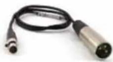
TA5 mini female locking XLR to full size male XLR for two channels of AES digital audio from DCHR.
MCTA5PT2

TA5F mini female locking XLR to dual pig tails for two channels of analog audio from DCHR; allows custom connectors to be installed.
MCTA5TA3F2

TA5F mini locking female XLR to dual TA3F mini locking XLRs, for two channels of analog audio from DCHR.
Accessories
26895
Replacement wire belt clip.

21926
USB cable for firmware updates
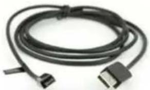
natural_image
Coiled black cable with two connectors, no visible text or symbolsLTBATELIM
Battery Eliminator for LT, DBu and DCHT transmitters, and M2R; camera hop and similar applications. Optional power cables include: P/N 21746 right angle, locking cable; 12 in. length P/N 21747 right angle, locking cable; 6 ft. length; DCR12/A5U universal power supply for AC power.

natural_image
Close-up of a black mechanical component with a central threaded part and multiple screws (no visible text or symbols)LRSHOE
This optional kit includes the accessories needed to mount the DCHR on a standard cold shoe, using the wire belt clip that comes with the receiver.

natural_image
Mechanical gear assembly with mounting bracket (no visible text or symbols)AMJ(xx) Rev. A
Whip antenna; swiveling. Specify frequency block (see chart below).

natural_image
Close-up of a black and blue pen-like tool with a blue handle, no visible text or symbols.AMM(xx)
Whip antenna; straight. Specify frequency block (see chart below).

natural_image
Close-up of a black and metallic cable with blue connectors, labeled 'RoHS' (no other text or symbols visible)About Whip Antenna Frequencies:
Frequencies for whip antennas are specified by the block number. For example, AMM-25 is the straight whip model cut to the block 25 frequency.
L-Series transmitters and receivers tune across a range covering three blocks. The correct antenna for each of these tuning ranges is the block in the middle of the tuning range.
Band Blocks covered Ant. Freq.
| A1 | 470, 19, 20 | Block 19 |
| B1 | 21, 22, 23 | Block 22 |
| C1 | 24, 25, 26 | Block 25 |
Specifications
Operating Frequencies: US: 470.100 - 614.375 MHz
Modulation Type: 8PSK with Forward Error Correction
Audio Performance:
Frequency Response: D2 mode: 25 Hz - 20 kHz, +0/-3 dB
Stereo mode: 20 Hz - 12 kHz, +0/-3 dB
THD+N: 0.05% (1kHz @ -10 dBFS)
Dynamic Range: >95 dB weighted
Adjacent Channel Isolation >85dB
Diversity Type: Switched antenna, during digital packet headers
Audio Output:
Analog: 2 balanced outputs
AES3: 2 channels, 48 kHz sample rate
Headphone Monitor: 3.5 mm TRS jack
Level (line level analog): -50 to +5dBu
Power requirements: 2 x AA batteries (3.0V)
Battery life: 8 hours; (2) Lithium AA
Power consumption: 1 W
Dimensions: Height: 3.0 in. / 120 mm. (with knob)
Width: 2.375 in. / 60.325 mm.
Depth: .625 in. / 15.875 mm.
Weight: 9.14 ounces / 259 grams (with batteries)
Specifications subject to change without notice.
Service and Repair
If your system malfunctions, you should attempt to correct or isolate the trouble before concluding that the equipment needs repair. Make sure you have followed the setup procedure and operating instructions. Check the interconnecting cables.
We strongly recommend that you do not try to repair the equipment yourself and do not have the local repair shop attempt anything other than the simplest repair. If the repair is more complicated than a broken wire or loose connection, send the unit to the factory for repair and service. Don't attempt to adjust any controls inside the units. Once set at the factory, the various controls and trimmers do not drift with age or vibration and never require readjustment. There are no adjustments inside that will make a malfunctioning unit start working.
LECTROSONICS' Service Department is equipped and staffed to quickly repair your equipment. In warranty repairs are made at no charge in accordance with the terms of the warranty. Out-of-warranty repairs are charged at a modest flat rate plus parts and shipping. Since it takes almost as much time and effort to determine what is wrong as it does to make the repair, there is a charge for an exact quotation. We will be happy to quote approximate charges by phone for out-of-warranty repairs.
Returning Units for Repair
For timely service, please follow the steps below:
A. DO NOT return equipment to the factory for repair without first contacting us by e-mail or by phone. We need to know the nature of the problem, the model number and the serial number of the equipment. We also need a phone number where you can be reached 8 A.M. to 4 P.M. (U.S. Mountain Standard Time).
B. After receiving your request, we will issue you a return authorization number (R.A.). This number will help speed your repair through our receiving and repair departments. The return authorization number must be clearly shown on the outside of the shipping container.
C. Pack the equipment carefully and ship to us, shipping costs prepaid. If necessary, we can provide you with the proper packing materials. UPS or FEDEX is usually the best way to ship the units. Heavy units should be "double-boxed" for safe transport.
D. We also strongly recommend that you insure the equipment, since we cannot be responsible for loss of or damage to equipment that you ship. Of course, we insure the equipment when we ship it back to you.
Lectrosonics USA:
Mailing address: Shipping address: Telephone:
Lectrosonics, Inc. Lectrosonics, Inc. +1 (505) 892-4501
PO Box 15900 561 Laser Rd., Suite 102 (800) 821-1121 Toll-free US and Canada
Rio Rancho, NM 87174 Rio Rancho, NM 87124 Fax +1 (505) 892-6243
USA USA
Web:
www.lectrosonics.com
E-mail:
service.repair@lectrosonics.com
sales@lectrosonics.com
Lectrosonics Canada:
Mailing Address:
720 Spadina Avenue, Suite 600
Toronto, Ontario M5S 2T9
Telephone:
+1 (416) 596-2202
(877) 753-2876 Toll-free Canada
(877) 7LECTRO
Fax (416) 596-6648
E-mail:
Sales: colinb@lectrosonics.com
Service: joeb@lectrosonics.com
LIMITED ONE YEAR WARRANTY
The equipment is warranted for one year from date of purchase against defects in materials or workmanship provided it was purchased from an authorized dealer. This warranty does not cover equipment which has been abused or damaged by careless handling or shipping. This warranty does not apply to used or demonstrator equipment.
Should any defect develop, Lectrosonics, Inc. will, at our option, repair or replace any defective parts without charge for either parts or labor. If Lectrosonics, Inc. cannot correct the defect in your equipment, it will be replaced at no charge with a similar new item. Lectrosonics, Inc. will pay for the cost of returning your equipment to you.
This warranty applies only to items returned to Lectrosonics, Inc. or an authorized dealer, shipping costs prepaid, within one year from the date of purchase.
This Limited Warranty is governed by the laws of the State of New Mexico. It states the entire liability of Lectrosonics Inc. and the entire remedy of the purchaser for any breach of warranty as outlined above. NEITHER LECTROSONICS, INC. NOR ANYONE INVOLVED IN THE PRODUCTION OR DELIVERY OF THE EQUIPMENT SHALL BE LIABLE FOR ANY INDIRECT, SPECIAL, PUNITIVE, CONSEQUENTIAL, OR INCIDENTAL DAMAGES ARISING OUT OF THE USE OR INABILITY TO USE THIS EQUIPMENT EVEN IF LECTROSONICS, INC. HAS BEEN ADVISED OF THE POSSIBILITY OF SUCH DAMAGES. IN NO EVENT SHALL THE LIABILITY OF LECTROSONICS, INC. EXCEED THE PURCHASE PRICE OF ANY DEFECTIVE EQUIPMENT.
This warranty gives you specific legal rights. You may have additional legal rights which vary from state to state.
- Digital Camera Hop Receiver
- Quick Start Steps
- Table of Contents
- DCHR Digital Stereo/Mono Receiver
- Smart Tuning (SmartTune™)
- Encryption
- RF Front-End with Tracking Filter
- Panels and Features
- Battery Status LED
- RF Link LED
- IR (infrared) Port
- Outputs
- Headphone Monitor
- Audio Jack (TA5M mini XLR):
- USB Port
- Battery Compartment
- Keypad and LCD Interface
- MENU/SEL Button
- BACK Button
- POWER Button
- Arrow Buttons
- Installing Batteries
- System Setup Procedure
- Step 1) Install Batteries and Turn Power On
- Step 2) Set Compatibility Mode
- Step 3) Set or Sync Frequency to match Transmitter
- Step 4) Set Encryption Key Type and Sync with Transmitter
- Step 6) Choose Audio Output Function
- Step 7) Verify RF and Audio Signals are Present
- RF level
- Diversity activity
- Battery life indicator
- Audio level
- Mixer mode
- Navigating the Menus
- DCHR LCD Menu Map
- Menu Item Descriptions
- RF Setup Menu
- SmartTune
- RF Frequency
- Frequency Scan
- Clear Scan
- Freq. Group Edit
- Audio Setup Menu
- Compat Modes
- Output Type
- Audio Polarity
- Sync/Encryption Menu
- Send Frequency
- Get Frequency
- Send All
- Get All
- Key Type
- Encryption Keys
- Encryption Key Management
- Make Key
- Wipe Key
- Send Key
- Tools/Settings
- Lock/Unlock
- TX Batt Setup
- RX Batt Setup
- Display Setup
- Backlight
- Locale
- About
- Audio Output Cables and Connectors
- MCDTA5TA3F
- MCDTA5XLRM
- MCTA5PT2
- MCTA5TA3F2
- Accessories
- 26895
- 21926
- LTBATELIM
- LRSHOE
- AMJ(xx) Rev. A
- AMM(xx)
- About Whip Antenna Frequencies:
- Specifications
- Audio Performance:
- Audio Output:
- Service and Repair
- Returning Units for Repair
- Lectrosonics USA:
- Lectrosonics Canada:
- LIMITED ONE YEAR WARRANTY
Brand : Lectrosonics
Model : DCHR
Category : Receiver