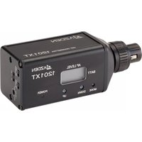
1201XT - Microphone Azden - Free user manual and instructions
Find the device manual for free 1201XT Azden in PDF.


| Product Type | UHF Wireless Handheld Transmitter |
| Brand | Azden |
| Model | 1201XT |
| Frequency Range | 638.125 – 661.875 MHz (188 selectable steps) |
| Modulation | MicroComputer Controlled PLL Synthesized |
| Noise Reduction | Expander (THAT) |
| Effective Operating Range | 200 – 300 ft (60 – 100 m) |
| Frequency Response | 50 – 15 kHz (±1.5 dB) |
| RF Output Power | 30 mW |
| Max Modulation Sensitivity | -4 dBm |
| Mic Level/Impedance (Dynamic) | -56 dBm (±5 kHz deviation) |
| Phantom Power | 48 V DC |
| Power Requirements | 3 V DC (2 × AA alkaline batteries) @ <180 mA, <290 mA with phantom power ON |
| Battery Life (approx.) | Up to 8 hours with alkaline batteries (estimated) |
| Dimensions (W × H × D) | 1.57 × 4.49 × 1.57 in (40 × 114 × 40 mm) |
| Microphone Connector | 3-pin XLR with locking ring (pin 1: GND, pin 2: audio+/48V, pin 3: audio-) |
| Input Level Adjustment | Screwdriver trimmer (clockwise increases gain) |
| Display | LCD showing frequency/channel, battery status (3 segments), audio level (5 segments), and cumulative hours of use |
| Audio Mute | Standby (STBY) switch maintains RF carrier but mutes audio |
| Operating Temperature Range | -10°C to +50°C (14°F to 122°F) |
| Licensing | User responsible for obtaining appropriate FCC license (USA) or local equivalent |
| Cable Length (output) | Not supplied; user must connect with proper XLR cable |
Frequently Asked Questions - 1201XT Azden
User questions about 1201XT Azden
0 question about this device. Answer the ones you know or ask your own.
Ask a new question about this device
Download the instructions for your Microphone in PDF format for free! Find your manual 1201XT - Azden and take your electronic device back in hand. On this page are published all the documents necessary for the use of your device. 1201XT by Azden.
USER MANUAL 1201XT Azden
RF Carrier Frequency Range 188 steps \~ 638.125 - 661.875 MHz
MicroComputer Controlled PLL Synth.
Noise Reduction Expander (THAT)
Effective Operating Range 200 - 300 ft - 60 - 100m
Frequency Response 50 - 15kHz (± 1.5dB)
RF Sensitivity (12dB SINAD) 1.2μV
Adjacent Channel Selectivity > 70dB (± 250kHz)
Image Rejection > 93dB
IF Rejection > 93dB
Audio THD < 0.8%
Audio Output 40dBm ± 40kHz Deviation (-20dBm ± 40kHz Deviation for 1201URX(Si)
Output Impedance 600Ω (300Ω for 1201URX:SI)
Signal/Noise Ratio > 62dB (± 5kHz Deviation) "A" Weighted
Power Requirements 11 - 15V DC @ 220mA (10 - 17V DC @ 200mA for 1201URXIS)
Dimensions
68W x 84H x 18D mm- 1201URX/Si insertion
93W x 119H x 49D mm - 1201URX/AB
82W x 150H x 60D mm - 1201URXVM
0^1 - + 122^ -10^ - + 50^
8.8 ounces \~ 250g for 1201URX/Si
15.87ounces \~ 450g for 1201URX/AB
26.45ounces \~ 750g for 1201URX/VM
Operating Temperature Range Weight
1201BT
Output Power
Max Modulation Sensitivity
MIC Level / Imped.
Power Requirements
Dimensions
Weight w/Battery
1201XT
Output Power
Max Modulation Sensitivity
MIC Level / Imped. (Dynamic)
Phantom Power
Power Requirements
Dimensions
Weight w/Battery
30mW
-4dBm
-56dBm (± 5kHz Deviation)
3V DC (2 "AA" Alkaline) @ < 150mA
2.48 (W) x 3.86 (H) x 1.12 (D) inches
3V DC (2 "AA" Alkaline) @ < 180mA - 290 mA w/Phantom Power ON
1.57 (W) × 4.49 (H) × 1.57 (D) inches
Due to constant improvements, specifications are subject to change without notice.
Licensing
Licensing of this, or any Azdan wireless equipment is the user's responsibility. The ability to receive a license depends largely on the user's classification, application and insurance. Contact the ownership company (FCG) in the USA for further information.
tion and frequency. Contact the appropriate agency (FCC in the USA) for further information.
Azden Corporation, 147 New Hyde Park Road, P.O. Box 10, Franklin Square, NY 11010
tel - 516.328.7500 • fax - 516.328.7506 • email - sales@azdencorp.com
User's Guide
1201URX/AB • 1201URX/VM • 1201URX/Si/Si-S
1201BT·1201XT
ENHANCED BROADCAST PERFORMANCE
UHF WIRELESS SYSTEM

natural_image
Exterior view of multiple JAZDEN 1201BT radio devices with visible antennas and ports (no text or symbols on main body)
AZDEN®
QUALITY YOU CAN HEAR

E. Display
In addition to showing the frequency and the channel number, the display [①] also shows other useful information.
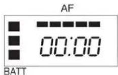
The LCD segments on the left show the approximate remaining battery life (from 1 to 3 segments) with 3 segments meaning maximum battery power. The bottom segment will blink when the battery power falls to less than 2.2VDC and indicates that it is time to replace the batteries. Azden recommends the use of Alkaline batteries only.
Across the top of the display up to 5 segments will illuminate depending on the strength of the transmitted audio signal - From 2 (weak) to 5 (strong). The first (left) segment will light when the AUDIO switch is turned ON. The best audio is achieved when 4 to 5 segments are lit. If all 5 segments are lit continually, the signal is too strong and could overload the input of the receiver. Move the microphone further away from the sound source.
The display can also show the total number of hours of use (change to this display using the mode [5] button. To start, after choosing the TIME mode, press the UP [6] Button until the display shows 00:00. Then, each time the transmitter is turned ON the clock will keep track of the total hours and minutes used. This is a handy way of keeping track of battery life.
USING THE 1201XT TRANSMITTER'S CONTROLS AND DISPLAY
A. Power
The POWER ON/OFF switch [ ] Turns the 1201XT ON or OFF.
B. Audio
Prior to turning the 1201XT ON it is best to set the AUDIO switch [ ] OFF. When ready to begin transmitting, switch to ON. The OFF position acts as a "mute" maintaining the RF signal but turning off the audio.

C. MIC Connector/Locking Ring
This 3-pin XLR connector [ ] is the microphone input. Any low impedance microphone with a corresponding connector can be attached here. If the microphone requires external power (Phantom Power) the 1201XT can supply 48VDC. The XLR connector is wired with pin #1 as ground, pin #2 as audio + (and +48VDC when Phantom Power is ON) and pin #3 as audio -.
Once the microphone is plugged into the 1201XT the locking ring [ ]④ should be rotated clockwise until snug. To remove the microphone, first rotate the locking ring counterclockwise and then, while pressing the XLR release, pull the microphone straight away from the 1201XT.
D. Input Level Adjustment
This screwdriver adjustment [ ] controls the input level of the microphone. Counterclockwise rotation reduces the input gain while clockwise rotation increases the input gain.
INTRODUCTION
Thank you for selecting the Azden 1201 Series for your portable/ENG on-camera UHF wireless needs. We are confident that these components will perform beyond your expectations. For over 50 years, Azden Corporation has been creating technologically advanced products. By taking advantage of the latest in CAD design and SMT production techniques, Azden's engineers are able to produce products that exceed the published specifications and perform well beyond the warranty period.
The 1201 Series represents a breakthrough in on-camera, digital frequency-selectable UHF receivers and transmitters. Its enhanced performance assures you of the highest image rejection combined with the finest in audio clarity. The PLL-synthesized mixer/local oscillator provides for extremely accurate frequency selection while the twin-antenna true diversity front-end reduces multi path distortion caused dropouts to near zero.
In the real world of ENG, the ability to be able to select a “clear” frequency on the spot is vitally important. Going out into the field with a single-frequency unit invites disaster since there is no way of knowing what frequencies will be used by the other crews that are covering the same story or event. Think of the 1201 Series units as your insurance policy - Your assurance of getting the story.
Designed by professionals - For professionals, the 1201 Series will provide you with years of worry-free, high-quality performance.
TABLE OF CONTENTS
1201URX SERIES RECEIVER VIEW i
INTRODUCTION ...... ii
RECEIVER (1201URX/AB and 1201URX/VM) SETUP ....1-2
Attaching the Antennas 1
Connecting the Output Cable 1
Setting the Receiver's Frequency 1-2
Power 2
Output 2
Monitor 2
LCD Display 2-4
The 1201URX/Si 4
Mode 4-5
Up/Down 5
Powering the 1201BT Transmitter ....6
SETTING THE TRANSMITTING FREQUENCY ON THE 1201BT ......6-7
USING THE 1201BT TRANSMITTER'S CONTROLS AND DISPLAY .....7
Power 7
Audio 7
MIC 7
Input Level Adjustment ....7
Belt Clip 7
Antenna 8
Display 8
THE 1201XT 8
Powering the 1201XT 8-9
SETTING THE TRANSMITTING FREQUENCY ON THE 1201XT ......9
USING THE 1201XT TRANSMITTER'S CONTROLS AND DISPLAY .....10
Power 10
Audio 10
MIC Connector / Locking Ring 10
Input Level Adjustment 10
Display 11
SPECIFICATIONS Back Page
LICENSING Back Page
CONFORMITY ....Insert
iii
POWERING THE 1201XT (continued)
in the illustration. The compartment is deigned to ease battery insertion - With the correct polarity. DO NOT FORCE THE BATTERY INTO THE COMPARTMENT. Azden does not recommend the use of rechargeable batteries.

natural_image
Technical line drawing of a connector with ports and internal components (no text or symbols)SETTING THE TRANSMITTING FREQUENCY ON THE 1201XT
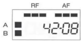
Before the 1201XT can be used, it and the associated receiver have to be set to the same frequency. This can be accomplished on the 1201XT transmitter by first setting the LCD display to one of the two views - 'Frequency' or 'Channel'. To do this ,after installing fresh batteries, turn the 1201XT to the ON position [⑨]. Next, using the tip of a ballpoint pen, an unbent paper clip or something similar, press the MODE button [⑤] repeatedly until one of the two screens below appears.
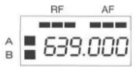

Using either the UP or DOWN button [⑥] the desired receiving frequency or channel number can be set. Tapping the button steps the frequency or channel number one at a time while pressing and holding the button in moves through the frequencies or channel numbers rapidly. There are 188 different frequencies or channel numbers to choose from. Once the desired frequency or channel number has been determined be certain to set both the transmitter and the receiver to match.
F. Antennas:
The antennas [②] should be kept clear of metal objects.
G. Display:
In addition to showing the frequency and channel number, the display [7] also shows other useful information.

The LCD segments on the left show the approximate remaining battery life (from 1 to 3 segments) with 3 segments meaning maximum battery power. The bottom segment will blink when the battery power falls to less the 2.2VDC and indicates that it is time to replace the batteries. Azden recommends the use of Alkaline batteries only.
Across the top of the display up to 5 segments will illuminate depending on the strength of the transmitted audio signal - From 2 (weak) to 5 (strong). The first (left) segment will light when the STBY switch is turned ON. The best audio is achieved when 4 to 5 segments are lit. If all 5 segments are lit continually, the signal is too strong and could overload the input of the receiver. Either move the microphone further away from the sound source or reduce the microphone input gain [ * ].
The display can also show the total number of hours of use (change to this display using the mode [8] button. To start, after choosing the TIME mode, press the UP [10] Button until the display shows 00:00. Then, each time the transmitter is turned ON the clock will keep track of the total hours and minutes used. This is a handy way of keeping track of battery life.
POWERING THE 1201XT TRANSMITTER
The 1201XT uses two "AA" Alkaline batteries for power. The batteries are placed in the compartment by removing the battery compartment door and placing the batteries in the compartment as shown
8
RECEIVER SETUP (1201URX/AB and 1201URX/VM)
The 1201URX/AB is a specially developed model that integrates the Anton Bauer "Gold Mount" to power the receiver. The 1201URX/VM is a specially developed model that integrates the IDX battery-mount to power the receiver. All of the functions and controls of the two models are the same except for the method of powering the receiver. The 1201URX/AB attaches between the camera and Anton Bauer pack using the "Gold Mount" system while the 1201URX/VM attaches between the camera and the IDX "V-mount" battery pack.
A. Attaching antennas:
To attach the high-gain antennas to the receiver, fit the BNC connector on the antenna on the receiver [①], press down and rotate clockwise. To remove, rotate the antenna's BNC connector counterclockwise and pull up.
B. Connecting the Output cable:
It is necessary to connect the output of the receiver [③] to the camera's "MIC" or "LINE" input by means of a properly wired cable (not supplied). The connector on the receiver is wired with pin #1 as Ground, pin #2 as Positive (+) and pin #3 as Negative (-). Set the OUTPUT Line/Mic switch on the receiver [⑧] to the appropriate position, matching the input on the camera that is used.
C. Setting the Receiving Frequency:
Before the receiver can be used, it and the associated transmitter have to be set to the same frequency. This can be accomplished on the receiver by first setting the LCD display to one of two views - "Frequency" or "Channel". To do this, after applying battery power, fist turn the receiver to the ON position [⑦]. Next, using the tip of a ballpoint pen, an unbent paperclip or something similar, press the MODE button [⑨] repeatedly until one of the two screens on the next page appears.
RECEIVER SETUP/USE - 1201URX/AB or 1201URX/VM (continued)

Using either the UP or DOWN button [10] the desired receiving frequency or channel number can be set. Tapping the button steps the frequency or channel number one at a time while pressing and holding the button moves through the frequencies or channel numbers rapidly. There are 188 different frequencies or channel numbers to choose from. Once the desired frequency or channel has been determined be certain to set both the transmitter and the receiver to match.
D. Power:
The POWER ON/OFF switch [7] turns the 1201BT On and Off. To conserve battery life, it is best to turn the receiver ON only when it is actually being used.
E. Output:
Select either LINE or MIC [⑧] depending on which input is being used on the camera
F. Monitor:
This control [⑤] adjusts the output level (MIN to MAX) at the earphone monitor jack [②]. This is a 3.5mm mono jack.
G. LCD Display:
This display [⑥] shows several pieces of information. As discussed previously, the frequency or channel number is shown. Additionally, as the diversity receiver chooses which antenna is receiving the best signal, The 'A' or 'B' segment of the LCD display will illuminate.
Using either the UP or DOWN button [⑩] the desired receiving frequency or channel number can be set. Tapping the button steps the frequency or channel number one at a time while pressing and holding the button moves through the frequencies or channel numbers rapidly. There are 188 different frequencies or channel numbers to choose from. Once the desired frequency or channel has been determined be certain to set both the transmitter and the receiver to match.
USING THE 1201 TRANSMITTER CONTROLS AND DISPLAY
A. Power:
The POWER ON/OFF switch [③] turns the 1201BT On and Off.
B. Audio:
Prior to turning the 1201BT ON it is best to set the AUDIO switch [⑤] to ST.BY. When ready to transmit, switch to ON. The ST.BY position acts as a "mute" that maintains the RF signal but turns off the audio.
C. MIC:
This 4-pin Hirose connector [©] is the microphone input. Azden produces a number of lapel, head-worn and neck-worn microphones that are specifically suited for the 1201BT. In addition, other externally powered (5VDC) electret condenser microphones can be used when they are properly wired with the correct Hirose connector) pin #1 is for audio +, pin #2 is not used, pin #3 is for bias voltage and pin #4 is ground). If you are using the 1201BT as a wireless instrument transmitter the connections are somewhat different (pin #1 is not used, pin #2 is audio +, pin #3 is for bias voltage and pin #4 is ground).
D. Input Level Adjustment:
This screwdriver adjustment [ * ] controls the level of the microphone. Counterclockwise rotation reduces the input gain while clockwise rotation increases the input gain.
E. Belt-Clip:
The metal belt-clip [①] provides a convenient method of attaching the transmitter to the user.
Powering the 1201BT Transmitter
The 1201BT uses 2 "AA" Alkaline batteries for power. The batteries are placed in the battery compartment by sliding the battery compartment door [⑤] down and placing the batteries in the compartment as marked [**]. DO NOT FORCE THE BATTERIES INTO THE COMPARTMENT. Azden does not recommend the use of rechargeable batteries.


SETTING THE TRANSMITTING FREQUENCY ON THE 1201BT
Before the 1201BT can be used, it and the associated receiver have to be set to the same frequency. This can be accomplished on the 1201BT transmitter by first setting the LCD display to one of two views - 'Frequency' or 'Channel'. To do this, after installing fresh batteries, turn the 1201BT to the ON position [③]. Next, using the tip of a ballpoint pen, an unbent paper clip or something similar, press the MODE button [⑧] repeatedly until one of the two screens below appears.


| Frequency | Display | Frequency | Display | Frequency | Display | Frequency | Display |
| 638.125 | 42-01 | 844.125 | 43-01 | 650.125 | 44-01 | 656.125 | 45-01 |
| 638.290 | 43-02 | 844.290 | 43-02 | 650.290 | 44-02 | 656.290 | 45-02 |
| 638.375 | 43-03 | 844.375 | 43-03 | 650.375 | 44-03 | 656.375 | 45-03 |
| 638.500 | 43-04 | 844.500 | 43-04 | 650.500 | 44-04 | 656.500 | 45-04 |
| 638.625 | 43-05 | 844.625 | 43-05 | 650.625 | 44-05 | 656.625 | 45-05 |
| 638.750 | 43-06 | 844.750 | 43-06 | 650.750 | 44-06 | 656.750 | 45-06 |
| 638.875 | 43-07 | 844.875 | 43-07 | 650.875 | 44-07 | 656.875 | 45-07 |
| 639.000 | 43-08 | 845.000 | 43-08 | 651.000 | 44-08 | 657.000 | 45-08 |
| 639.125 | 43-09 | 845.125 | 43-09 | 651.125 | 44-09 | 657.125 | 45-09 |
| 639.290 | 43-10 | 845.290 | 43-10 | 651.290 | 44-10 | 657.290 | 45-10 |
| 639.375 | 43-11 | 845.375 | 43-11 | 651.375 | 44-11 | 657.375 | 45-11 |
| 639.500 | 43-12 | 845.500 | 43-12 | 651.500 | 44-12 | 657.500 | 45-12 |
| 639.625 | 43-13 | 845.625 | 43-13 | 651.625 | 44-13 | 657.625 | 45-13 |
| 639.750 | 43-14 | 845.750 | 43-14 | 651.750 | 44-14 | 657.750 | 45-14 |
| 639.875 | 43-15 | 845.875 | 43-15 | 651.875 | 44-15 | 657.875 | 45-15 |
| 640.000 | 43-16 | 846.000 | 43-16 | 652.000 | 44-16 | 658.000 | 45-16 |
| 640.125 | 43-17 | 846.125 | 43-17 | 652.125 | 44-17 | 658.125 | 45-17 |
| 640.250 | 43-18 | 846.250 | 43-18 | 652.250 | 44-18 | 658.250 | 45-18 |
| 640.375 | 43-19 | 846.375 | 43-19 | 652.375 | 44-19 | 658.375 | 45-19 |
| 640.500 | 43-20 | 846.500 | 43-20 | 652.500 | 44-20 | 658.500 | 45-20 |
| 640.625 | 43-21 | 846.625 | 43-21 | 652.625 | 44-21 | 658.625 | 45-21 |
| 640.750 | 43-22 | 846.750 | 43-22 | 652.750 | 44-22 | 658.750 | 45-22 |
| 640.875 | 43-23 | 846.875 | 43-23 | 652.875 | 44-23 | 658.875 | 45-23 |
| 641.000 | 43-24 | 847.000 | 43-24 | 653.000 | 44-24 | 658.000 | 45-24 |
| 641.125 | 43-25 | 847.125 | 43-25 | 653.125 | 44-25 | 658.125 | 45-25 |
| 641.250 | 43-26 | 847.290 | 43-26 | 653.290 | 44-26 | 658.290 | 45-26 |
| 641.375 | 43-27 | 847.375 | 43-27 | 653.375 | 44-27 | 658.375 | 45-27 |
| 641.500 | 43-28 | 847.500 | 43-28 | 653.500 | 44-28 | 659.500 | 45-28 |
| 641.625 | 43-29 | 847.625 | 43-29 | 653.625 | 44-29 | 659.625 | 45-29 |
| 641.750 | 43-30 | 847.750 | 43-30 | 653.750 | 44-30 | 659.750 | 45-30 |
| 641.875 | 43-31 | 847.875 | 43-31 | 653.875 | 44-31 | 659.875 | 45-31 |
| 642.000 | 43-32 | 848.000 | 43-32 | 654.000 | 44-32 | 660.000 | 45-32 |
| 642.125 | 43-33 | 848.125 | 43-33 | 654.125 | 44-33 | 660.125 | 45-33 |
| 642.250 | 43-34 | 848.290 | 43-34 | 654.290 | 44-34 | 660.290 | 45-34 |
| 642.375 | 43-35 | 848.375 | 43-35 | 654.375 | 44-35 | 660.375 | 45-35 |
| 642.500 | 43-36 | 848.500 | 43-36 | 654.500 | 44-36 | 660.500 | 45-36 |
| 642.625 | 43-37 | 848.625 | 43-37 | 654.625 | 44-37 | 660.625 | 45-37 |
| 642.750 | 43-38 | 848.750 | 43-38 | 654.750 | 44-38 | 660.750 | 45-38 |
| 642.875 | 43-39 | 848.875 | 43-39 | 654.875 | 44-39 | 660.875 | 45-39 |
| 643.000 | 43-40 | 849.000 | 43-40 | 655.000 | 44-40 | 661.000 | 45-40 |
| 643.125 | 43-41 | 849.125 | 43-41 | 655.125 | 44-41 | 661.125 | 45-41 |
| 643.250 | 43-42 | 849.290 | 43-42 | 655.290 | 44-42 | 661.290 | 45-42 |
| 643.375 | 43-43 | 849.375 | 43-43 | 655.375 | 44-43 | 661.375 | 45-43 |
| 643.500 | 43-44 | 849.500 | 43-44 | 655.500 | 44-44 | 661.500 | 45-44 |
| 643.625 | 43-45 | 849.625 | 43-45 | 655.625 | 44-45 | 661.625 | 45-45 |
| 643.750 | 43-46 | 849.750 | 43-46 | 655.750 | 44-46 | 661.750 | 45-46 |
| 643.875 | 43-47 | 849.875 | 43-47 | 655.875 | 44-47 | 661.875 | 45-47 |
[GR-1\~6]
| Group Disp - Freq. | CH 01 | CH 02 | CH 03 | CH 04 | CH 05 | CH 06 | CH 07 | CH 08 | CH 09 | CH 10 | CH 11 | CH 12 |
| GR 1 | 638.625 | 639.750 | 641.125 | 643.125 | 643.875 | 645.500 | 649.000 | 647.750 | 648.625 | 649.000 | 649.250 | |
| GR 2 | 644.125 | 644.625 | 645.375 | 647.125 | 647.500 | 648.500 | 649.125 | 649.375 | ||||
| GR 3 | 639.375 | 639.825 | 640.250 | 641.250 | 642.625 | 643.000 | 643.500 | 643.750 | ||||
| GR 4 | 650.625 | 651.750 | 653.125 | 655.125 | 655.875 | 657.500 | 658.000 | 659.750 | 660.625 | 661.000 | 661.250 | |
| GR 5 | 656.125 | 656.825 | 657.375 | 659.125 | 659.500 | 660.900 | 661.125 | 661.375 | ||||
| GR 6 | 650.375 | 651.825 | 652.250 | 653.250 | 654.625 | 655.000 | 655.500 | 655.750 | ||||
| Group Disp - CH. | CH 01 | CH 02 | CH 03 | CH 04 | CH 05 | CH 06 | CH 07 | CH 08 | CH 09 | CH 10 | CH 11 | CH 12 |
| GR 1 | 42 - 05 | 42 - 14 | 42 - 25 | 42 - 41 | 42 - 47 | 43 - 12 | 43 - 16 | 43 - 30 | 43 - 37 | 43 - 40 | 43 - 42 | |
| GR 2 | 43 - 01 | 43 - 05 | 43 - 11 | 43 - 25 | 43 - 28 | 43 - 36 | 43 - 41 | 43 - 43 | ||||
| GR 3 | 42 - 03 | 42 - 13 | 42 - 10 | 42 - 26 | 42 - 37 | 42 - 40 | 42 - 44 | 42 - 48 | ||||
| GR 4 | 44 - 05 | 44 - 14 | 44 - 25 | 44 - 41 | 44 - 47 | 45 - 12 | 45 - 16 | 45 - 30 | 45 - 37 | 45 - 40 | 45 - 42 | |
| GR 5 | 43 - 01 | 45 - 00 | 43 - 11 | 43 - 25 | 43 - 28 | 43 - 36 | 43 - 41 | 43 - 43 | ||||
| GR 6 | 44 - 03 | 44 - 12 | 44 - 18 | 44 - 26 | 44 - 37 | 44 - 40 | 44 - 44 | 44 - 48 |
RECEIVER SETUP/USE - 1201URX/AB or 1201URX/VM
As the RF signal from the transmitter gets stronger (or weaker) the number of illuminated LCD segments in the display will change - with 3 segments being the maximum and best. Similarly, the AF (audio level) segments will light from 1 to 3 segments as the audio gets stronger or weaker. In this case, the best level is achieved as the display shows between 2 and 3 segments. If all 3 segments stay illuminated for a continued period of time it is likely that you are over-driving the receiver's input and you should reduce the transmitting level by either moving the microphone further away from the sound source or reducing the input gain on the transmitter.
THE 1201URX/Si
The 1201URX/Si receiver is specially designed to work with specific Panasonic "Slot-In" or Ikegami "Uni-Slot" cameras. Once mounted in the camera, the DB-25 connector on the bottom provides the receiver with power directly from the camera's power supply (battery) while delivering audio directly to the camera's audio input. Items A. [⑪], C., D. [⑦] and G. [⑥] on pages 1 and 2 apply directly to the 1201URX/Si
1201URX/Si Top panel display and operation:
The MODE Switch [⑨] performs 1 of 5 functions.
Initial MODE display:
The initial MODE shows the receiving band shown as Group, Channel and Frequency. If there is no action taken with the MODE switch for 4 seconds the display will return to the Initial Display. Pressing the MODE switch for one second while showing the Initial Display will cause the currently set frequency to be displayed.
Mode #1 (GR):
From the Initial Display, quickly pressing the MODE switch once displays the Group Display. Pressing the UP or DOWN buttons will change the Group Number. There are 7 Groups, 6 of which have the best selection of frequency combinations when using multiple systems. Group 0 allows for choosing any channel/frequency. The last Group is memorized when the receiver is turned OFF. The chart on page 3 shows the Group vs Frequency combinations.
1201URX/Si Top Panel display and operation (continued)
Mode #2 (CH):
To change the channel/frequency within the selected group, press the MODE switch a 2nd time. "CH" will be displayed. Using either the UP or DOWN button[] the desired receiving channel/frequency combination can be set (the chart on page 3 shows the relationship). Tapping the button steps the channel/frequency number one at a time while pressing and holding the button moves through the combinations rapidly. There are 188 different channel/frequency combinations to choose from "Group" allows you to select all of the combinations). Once the desired channel/frequency has been determined set both the transmitter and receiver to match. When the receiver is turned OFF the last channel/frequency chosen is stored in memory.
Mode #3 (SQ):
To change the squelch level, press the MODE switch for a third time. "SQ" will show in the display. There are 3 settings to choose from:
$$ \begin{array}{l} \text { on on } = \text { RF mute ON - Tone mute ON (default) } \ \text { on off } = \text { RF mute ON - Tone mute OFF } \ \text { off off } = \text { RF mute OFF - Tone mute OFF } \ \end{array} $$
You can cycle through these with the UP/DOWN buttons. The squelch returns to the default when the receiver is turned OFF.
Mode #4 (SQ Level):
There are four levels of Squelch to choose from:
0 = Default
3 = 3dB (RF) increase to the default
-6 = 6dB (RF) decrease to the default
-3 = 3dB (RF) decrease to the default
You can cycle through these with the UP/DOWN buttons.
See the discussion at the bottom of page 2 and the top of page 4 for information concerning the other parts of the display.
- User's Guide
- Display
- USING THE 1201XT TRANSMITTER'S CONTROLS AND DISPLAY
- Power
- Audio
- MIC Connector/Locking Ring
- Input Level Adjustment
- INTRODUCTION
- TABLE OF CONTENTS
- POWERING THE 1201XT (continued)
- SETTING THE TRANSMITTING FREQUENCY ON THE 1201XT
- Antennas:
- Display:
- POWERING THE 1201XT TRANSMITTER
- RECEIVER SETUP (1201URX/AB and 1201URX/VM)
- Attaching antennas:
- Connecting the Output cable:
- Setting the Receiving Frequency:
- RECEIVER SETUP/USE - 1201URX/AB or 1201URX/VM (continued)
- Power:
- Output:
- Monitor:
- LCD Display:
- USING THE 1201 TRANSMITTER CONTROLS AND DISPLAY
- Power:
- Audio:
- MIC:
- Input Level Adjustment:
- Belt-Clip:
- Powering the 1201BT Transmitter
- SETTING THE TRANSMITTING FREQUENCY ON THE 1201BT
- RECEIVER SETUP/USE - 1201URX/AB or 1201URX/VM
- THE 1201URX/Si
- 1201URX/Si Top panel display and operation:
- Initial MODE display:
- Mode #1 (GR):
- 1201URX/Si Top Panel display and operation (continued)
- Mode #2 (CH):
- Mode #3 (SQ):
- Mode #4 (SQ Level):
Brand : Azden
Model : 1201XT
Category : Microphone