
IVA 4.0 - Unknown BOSCH - Free user manual and instructions
Find the device manual for free IVA 4.0 BOSCH in PDF.


| Product Type | Intelligent Video Analytics Module |
| Model | IVA 4.0 |
| Brand | Bosch |
| Compatible Cameras | Bosch IP cameras with compatible firmware |
| Video Analytics Functions | Motion detection, object tracking, line crossing, intrusion detection, loitering detection, object removal, scene change |
| Max Number of Simultaneous Objects | Up to 128 objects |
| Analysis Modes | Live and recorded video |
| Supported Video Codecs | H.264, H.265, MJPEG |
| Integration | Via Bosch Video Management System (BVMS) or third-party software with SDK |
| Configuration Interface | Web browser or Bosch Configuration Manager |
| Firmware Upgrade | Via network |
| Security | Encrypted communications (HTTPS), user authentication |
| Environmental Operating Temperature | 0 °C to 50 °C |
| Storage Temperature | -20 °C to 70 °C |
| Relative Humidity | 20% to 80% non-condensing |
| Power Supply | Powered via PoE (IEEE 802.3af/at) or 12V DC |
| Power Consumption | Typical 5 W |
| Dimensions (Approx.) | Not applicable (software module) |
| Weight | Not applicable (software module) |
| Warranty | Standard Bosch warranty (usually 2 years) |
Frequently Asked Questions - IVA 4.0 BOSCH
User questions about IVA 4.0 BOSCH
0 question about this device. Answer the ones you know or ask your own.
Ask a new question about this device
Download the instructions for your Unknown in PDF format for free! Find your manual IVA 4.0 - BOSCH and take your electronic device back in hand. On this page are published all the documents necessary for the use of your device. IVA 4.0 by BOSCH.
USER MANUAL IVA 4.0 BOSCH
natural_image
Aerial view of a bus crossing a red-lit urban intersection with vehicles and pedestrians (no visible text or signage)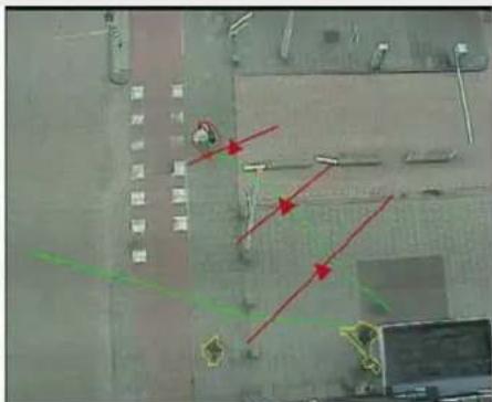
natural_image
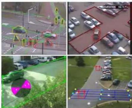
Four-panel aerial view of a parking lot with vehicles, parking areas, and outdoor park layout (no visible text or symbols)IVA 4.0
Intelligent Video Analysis

BOSCH
en Operating Manual
Table of Contents
1 Introduction 5
1.1 Welcome to the IVA Intelligent Video Analysis Help 5
1.2 About this Manual 5
1.3 Conventions in this Manual 5
1.4 Intelligent Video Analysis 5
| 2 | R | e | q | u | i | r | e | m | e |
| 2.1 Setup | 7 | ||||||||
| 2.2 Forensic Search in Recordings | 7 | ||||||||
| 2.3 License | 7 | ||||||||
| 2.4 Limitations | 9 |
3 Configuration 11
| 3.1 Configuration with Configuration Manager | 11 |
| 3.2 Configuration Using Web Browser | 12 |
4 IVA 4.0 14
| 4.1 The Basics | 14 | |
| 4.2 Object Outlines and Other Image Information | 16 | |
| 4.3 IVA 4.0 User Interface | 17 | |
| 4.3.1 | Popup Menu in the Camera Image | 19 |
| 4.3.2 | The IVA Task Editor | 22 |
| 4.4 Tasks | 22 | |
| 4.5 Creating/Editing a Task | 23 | |
| 4.5.1 | Default Task | 24 |
| 4.5.2 | Object in field | 24 |
| 4.5.3 | Crossing line | 30 |
| 4.5.4 | Loitering | 31 |
| 4.5.5 | Condition change | 32 |
| 4.5.6 | Following route | 33 |
| 4.5.7 | Tampering | 34 |
| 4.5.8 | Removed object | 35 |
| 4.5.9 | Idle object | 35 |
| 4.5.10 | Entering field | 36 |
| 4.5.11 | Leaving field | 36 |
| 4.5.12 | Similarity search | 37 |
| 4.6 Statistics | 38 | |
| 4.7 Configuration | 38 | |
| 4.7.1 | Calibration | 39 |
| 4.7.2 | Global Settings | 44 |
| 4.7.3 | Sensitive Area | 46 |
| 4.8 Object Properties | 47 | |
5 IVA 4.0 Flow 49
| 5.1 The Basics and Image Information | 49 |
4 en | Table of Contents IVA 4.0
5.2 IVA 4.0 Flow User Interface 49
5.2.1 Popup Menu in the Camera Image 51
5.3 Tasks 52
5.4 Creating/Editing a Task 53
5.4.1 Default Task 53
5.4.2 Tampering 53
5.4.3 Flow in field 54
5.4.4 Counterflow in field 55
5.5 Statistics 56
5.6 Configuration 57
5.6.1 Sensitivity Settings 57
6 IVA and VG4 AutoDome 58
7 Display of Units of Measurement 59
Index 60
1 Introduction
1.1 Welcome to the IVA Intelligent Video Analysis Help
1.2 About this Manual
This manual is intended for persons who will operate IVA 4.0 or IVA 4.0 Flow. The manual describes how to operate IVA 4.0 or IVA 4.0 Flow.
1.3 Conventions in this Manual
In this manual, the following symbols and notations are used to draw attention to special situations:

CAUTION!
Security instructions where non-compliance can result in loss of data are marked with this symbol.

NOTICE!
This symbol indicates special features and provides tips and information for easier, more convenient use of the software.
Terms that you can find in the program, such as menu options or commands, are written in bold.
1.4 Intelligent Video Analysis
Bosch IVA 4.0 (Intelligent Video Analysis), with the auxiliary function IVA 4.0 Flow is an algorithm that detects certain properties and the behavior of objects in a scene monitored by a video camera and from this generates alarm events that, in turn, can be processed in a CCTV system.
Recording with activated IVA 4.0 settings is required in order to be able to later search through the video material quickly and purposefully using this algorithm.
IVA 4.0 makes it possible to capture and evaluate directional movement of objects in such a way that false alarms are prevented to a large extent.
IVA 4.0 adapts automatically to changing environmental conditions and is therefore largely non-sensitive to perturbing influences such as rain and tree movement.
Specifically when used for a forensic search, IVA 4.0 allows moving objects to be filtered according to their color. Using the IVA 4.0 algorithm, extensive video material can be specifically searched for objects with particular color properties.
New IVA 4.0 Functions
- Head detection: Objects can be identified as people by means of typical features.
- Similarity search: Objects can be detected on the basis of their similarity to other objects that have already been classified.
- IVA 4.0 Flow auxiliary function: A uniform optical flow is detected largely irrespective of the structure of the background and the size of individual objects. A flow in the opposite direction to the general direction of movement can also be defined as an alarm-triggering event.
IVA 4.0 Flow is used to detect uniform movement flows and movements against the general flow.
- Camera calibration for IVA 4.0: Enhanced calibration options with a choice of two calibration modes.
2 Requirements
2.1 Setup
The easiest way to set up IVA 4.0 and IVA 4.0 Flow is using the Configuration Manager program. This must be installed on a Windows PC that can communicate with the respective device over a network.
You will find a current version of the Configuration Manager program on the CD received when you purchased the license.
Operational requirements for the Configuration Manager program can be found in the documentation supplied.
Configuration Manager does not have to be licensed.
No additional programs are required to analyze live images.
Alternatively, you can also configure IVA 4.0 and IVA 4.0 Flow using the Web browser view of the device.
IVA 4.0-Compatible Senders and Cameras
IVA 4.0 is also available on the following devices:
- Dinion IP
- VideoJet X series
- VideoJet X SN series
- VIP X1600
- VG4 AutoDome IP
- FlexiDome IP
- E x t r e m e l P
2.2 Forensic Search in Recordings
The functionality of IVA 4.0 is also used in searches for objects in recordings. Moving objects can be detected by their behavior (for example, direction, speed, sudden appearance or disappearance) and according to their properties (for example, size or color). You will need the Archive Player program for this.
You will find the current version of the Archive Player program on the CD received when you purchased the license.
To use IVA 4.0 for movement analysis in recordings, the recordings must already have been created using a device (or a camera) with IVA 4.0 settings activated accordingly.

NOTICE!
Objects can be detected both in live images and in recordings, only in the area marked as sensitive.
Install the Configuration Manager and Archive Player programs from the IVA 4.0 CD. Doing so ensures that you are using the versions that are compatible with IVA 4.0.
2.3 License
When you purchase IVA 4.0 you will be provided with an authorization number via e-mail.
Using this number and the installation code that you will find in the Web browser view of the device, you can generate the activation key on the Bosch Software License Manager Internet platform.
This key is then entered in the Web browser view of the device. Then you can use IVA 4.0.
- Open the Web browser view of the device for which you would like to license IVA 4.0.
2. Select SETTINGS > Advanced Mode > Service > Licenses.
Make a note of the installation code — the copy-and-paste function is supported.
Requesting Activation Keys
3. Open the following Website from any PC:
https://activation.boschsecurity.com/
You will find a direct link to this Website under Tools on the IVA 4.0 CD.
The Bosch Security Systems Software License Manager user interface will appear. The page appears in English only.
4. If you already have an account, log in.
You can create a new account if you wish. The benefit of an account is that you can list all of your previous license activations.
Once you have logged in, the welcome dialog will appear.
You can also continue the process without logging in.
Next, you will see the License Activation screen.
5. Enter the authorization number that you received when you purchased IVA 4.0.
6. Then click the check mark next to the input window.
7. The next step is to enter the installation code along with brief information about the installation location. You may also add a comment.
This information will assist you later in assigning the activation key to the device.
8. Click Submit.
The activation key is displayed.
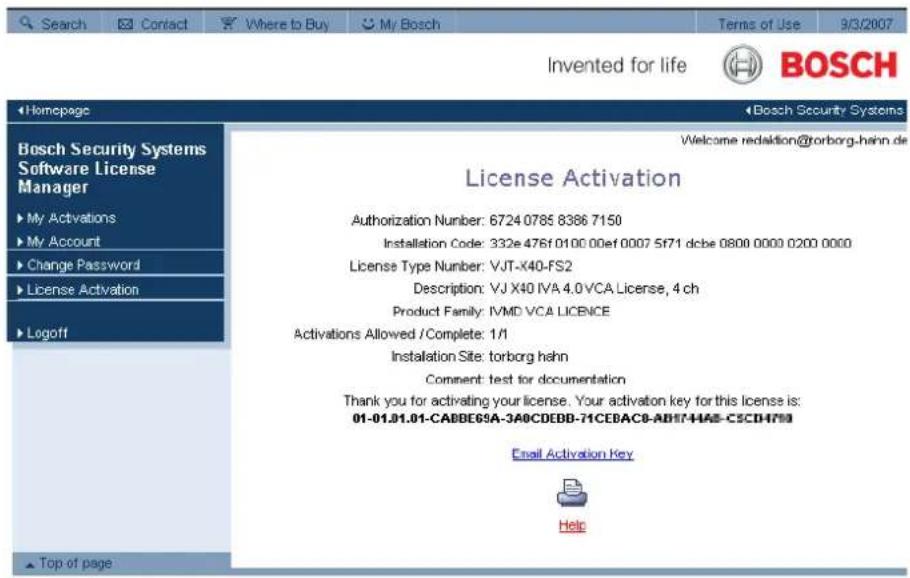
You can copy the key to the clipboard.
You can have the key e-mailed to you. To do this, click the Email Activation Key link. You will see a dialog box in which you can enter two e-mail addresses for recipients.
You can print the page.
Entering Activation Keys
9. Open the Web browser view of the device again.
-
Select SETTINGS > Advanced Mode > Service > Licenses again.
-
Enter the activation key — the copy-and-paste function is supported.
-
Click Set to save the activation key. A window tells you that licensing was successful.
-
Close the window.
IVA 4.0 is now activated. The activation key can no longer be seen.
Upgrade from IVA 3.5
If you have already licensed IVA 3.5 for the device, you simply need to upgrade the firmware of the device to version 4.0 or higher. The license for IVA 3.0 is then automatically changed to an IVA 4.0 license. Relicensing is not necessary.
You obtain the current firmware from your customer service or from the download area on our Internet site.
You can update the firmware directly via the Web browser view of the device or by using Configuration Manager. For detailed information on this process, please see the appropriate documentation.
2.4 Limitations
Please note the following considerations:
IVA 4.0 is suitable for monitoring boundaries, fences and enclosures and for the protection of pipelines, overland lines, car parks etc.
However, in certain environments the use of this type of motion detection system may not always be advisable; this is because movements may not always be detected or too many movements may be detected owing to reflections.
Movements may be falsely detected if there is:
- a reflective metal background
- glass (glazed building frontages)
- water as a background
- cones of light moving in darkness
Large areas of reflected light can also cause spurious motion detection. However, light reflections caused by falling raindrops, for example, are small enough to be ignored for statistical purposes and owing to the uniform nature of their motion.
Objects that always move uniformly (such as clouds) do not impair the detection of other objects and do not trigger false alarms.
A constant background is necessary in order to detect motion reliably and to assign that motion to a particular object. The more the background moves, the harder it is to distinguish moving objects from it. For instance, a person walking in front of a hedge that is moving in the wind will very probably not be detected.
If the image consists to a certain extent of nothing but moving objects — in other words, if objects cannot be distinguished from each other or from the background — the motion of an individual object cannot be detected (for example, individuals in a large crowd). In this scenario, IVA 4.0 Flow can detect uniform movement flows.
If a very large number of objects are detected, a lot of computing power will be required – this will reduce the power that is available for the transmission of live video data. If necessary, change the settings so that only relevant objects are detected.
IVA 4.0 and the associated configuration menus offer a number of simple ways to overcome these limitations and eliminate problem areas.
Note:
- If you are analyzing movement in live images, the computing power of the device (sender or camera) is challenged.
- During motion analysis in recordings, the computing power of the PC, on which IVA 4.0 is used via Archive Player, is challenged.
If you are specifically looking for moving objects with certain color properties, take the following into consideration:
- An object is almost never displayed in a consistent color in the image data. Pixels on the outer edge of a detected object in particular often contain the color information of the background and not the object.
Objects such as automobiles comprise a variety of parts (body, windows, tires). Each individual part of the object is displayed in a different color — the mudguards in red, for example, and the tires in black.
- The color properties of an object depend upon the lighting conditions. If the lighting conditions in a captured image change, then the captured color of the object will also change.
Objects on a street appear in different hues depending on the time of day and weather conditions.
- An object that changes its position or direction of movement may then appear with different color properties.
For example, automobiles are often marked on the side in color but not on the back.
When people are seen from the front, the hue of the face determines the color impression; however, if the person turns around, the color properties are then defined by the hair or headdress.
3 Configuration
IVA 4.0 and IVA 4.0 Flow are set up using the Configuration Manager program or via the Web browser view of the device.
You must move the camera to the required position first in each case. When using
VG4 AutoDome, the individual presets must be specified before configuring IVA 4.0 for each preset.
All of the settings you make relate to the selected camera position. This means that you must reconfigure IVA 4.0 for this camera whenever you change the camera's direction or position.
For more details, also refer to: Section 6 IVA and VG4 AutoDome, page 58.
3.1 Configuration with Configuration Manager
Configuration Manager can be installed on any Windows PC.
The system requirements and operation of Configuration Manager are described in the Configuration Manager Installation and Operating Manual. You can access the online Help for Configuration Manager by selecting Help > Online Help... when you are in Configuration Manager.
-
Start Configuration Manager.
-
Make sure the File > Advanced Mode option is active.
-
From the Devices main tab, select the device for which you would like to configure IVA 4.0
or
from the Cameras main tab, select the camera for which you would like to configure IVA 4.0.
- In the display area, click the VCA tab to switch to Video Content Analysis.
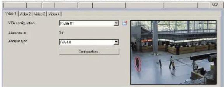
The camera image appears on the right. You see an individual image that is refreshed at regular intervals.
- Under VCA configuration, select either Profile 1 or Profile 2.
If necessary, change the name of a profile by clicking

There are ten profiles available for VG4 AutoDome. Each profile can be used for one preset.
- VG4 AutoDome only: Select an entry from the list under Domescene.
The camera positions for individual presets must be defined in advance. These presets may already be named individually.
Only presets that are not yet linked to one of the profiles are available.
7. Select IVA 4.0 or IVA 4.0 Flow as the Analysis type.
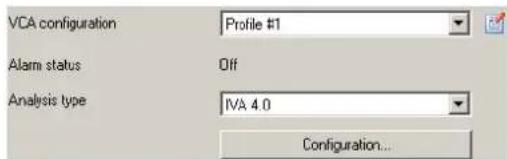
If you change the analysis type, the motion detection and tamper detection parameters revert to the default settings.
As soon as the analysis becomes active, meta data is generated and, depending on the configuration, additional information is overlaid on top of the camera image — an object bounding box for example.
8. Click Configuration....
The IVA Wizard window opens. IVA 4.0 and IVA 4.0 Flow are configured via this window. Please see the following for details on the configuration options:
- Section 4 IVA 4.0, page 14
- Section 5 IVA 4.0 Flow, page 49
If the IVA Wizard is already in use by another user, you will receive a message to that effect. The configuration window cannot be opened again at the same time.
Alarm status
This field shows whether IVA 4.0 has generated an alarm event with the current settings.
3.2 Configuration Using Web Browser
You can also configure IVA 4.0 using the Web browser view of the device.
-
Open the Web browser view of the device.
-
Select SETTINGS > Advanced Mode > Alarm > VCA to switch to Video Content Analysis. The camera image appears on the right.
-
Under VCA configuration, select either Profile 1 or Profile 2.
If necessary, change the name of a profile by clicking

There are ten profiles available for VG4 AutoDome. Each profile can be used for one preset.
- VG4 AutoDome only: Select an entry from the list under Domescene.
The camera positions for individual presets must be defined in advance. These presets may already be named individually.
Only presets that are not yet linked to one of the profiles are available.
- Select IVA 4.0 or IVA 4.0 Flow as the Analysis type.
If you change the analysis type, the motion detection and tamper detection parameters revert to the default settings.
As soon as the analysis becomes active, meta data is generated and, depending on the configuration, additional information is overlaid on top of the camera image — an object bounding box for example.
6. Click Configuration....
The Settings window opens. IVA 4.0 and IVA 4.0 Flow are configured via this window. Please see the following for details on the configuration options:
- Section 4 IVA 4.0, page 14
- Section 5 IVA 4.0 Flow, page 49
If the IVA Wizard is already in use by another user, you will receive a message to that effect.
The configuration window cannot be opened again at the same time.
Alarm status
This field shows whether IVA 4.0 has generated an alarm event with the current settings.
4
|
V
A
4
•
This chapter provides a description of the program, the configuration and the various IVA 4.0 settings.
For details on configuring IVA 4.0 Flow, please refer to: Section 5 IVA 4.0 Flow, page 49.
4.1 The Basics
The camera 'sees' a selected area. This area is displayed in the Configuration Manager program as a single, constantly refreshed image. In the Web browser view of the device you will see a live video preview.
Objects
Objects are typically people or vehicles moving within the area seen by the camera. Objects can be filtered according to certain properties (size, aspect ratio, direction of movement, speed, location, color). An alarm event can be generated if objects match certain parameters. Objects that do not match the criteria you define are filtered out and do not generate an alarm event.
It is always the center of an object that is relevant for generating an alarm event.
Sensitive Area
The scene that is captured by a camera often includes areas that are irrelevant for alarm event generation (such as sky). You can reduce the size of the area that is actually analyzed for motion.
This will make motion detection for the remaining — sensitive — area correspondingly faster and more effective.

NOTICE!
Please note that when using IVA 4.0 for a forensic search in recordings, motion analysis is only possible in the area that was previously marked as the sensitive area in the recording.
Calibration
If you wish to detect objects correctly according to their size or speed, a link must be made for each camera position between the size of the real-life situation and the dimensions as they appear on the camera image. For example, you must tell the software that an object that appears on the camera image with a height of 50 pixels is around 2 m high in reality. The camera angle is used to compute object speeds.
For more information, please see the description on calibration (see: Section 4.7.1 Calibration, page 39).

NOTICE!
The unit of measurement display can be adapted so that when the English language user interface is used, the relevant "imperial measurements" used in the English-speaking world are displayed (see: Section 7 Display of Units of Measurement, page 59).
Field
Fields are polygons that cover a certain area, for example an entrance or the open space in front of a barrier. These fields are created by you. Objects that move within a field can lead to the generation of an alarm event.
Line
A line can be compared to a virtual trip wire. Objects that cross a line you have defined in a pre-defined direction can trigger an alarm event.
Route
Objects that move along a route you have defined in a pre-defined direction can trigger an alarm event. It is possible to include deviations from this route using the relevant tolerance defaults.

NOTICE!
You can create up to 16 fields, 16 lines and 8 routes (as routes are counted twice). The total sum of these items cannot be greater than 16. If this limit is reached, no additional items can be created.
Color
The color properties of an object are mainly used in forensic searches to detect moving objects by their color. As objects rarely appear in one single color, the colors are detected by analyzing the different proportions of color according to their frequency. This means that, for example, you can search for objects that consist of up to 25% dark red pixels but also include up to 20% light gray pixels at the same time.
Color properties used for filtering can be adopted and refined using a marked object.

NOTICE!
The detection of color is not possible for objects that are only displayed with very few pixels.
Task
Tasks are the central control element in the IVA 4.0 setup. The aim of a task is to generate an alarm event in precisely defined situations.
A task can be created using a wizard. Expert users can adapt tasks created in this way to individual requirements using additions in the script.
Tasks can be activated or deactivated at any time.
You can define up to eight tasks.
Wizard
To make it easier to create and edit tasks, certain tasks have wizards that guide you through the creation of a task in a few steps. During this process, you are asked to define all of the parameters required for the task.
Filter Hierarchy
IVA 4.0 offers a series of filter options so you can adapt the analysis to your requirements. You exclude certain objects or areas from the analysis in order
- to avoid false alarms
and
- not to increase the computing power of the device unnecessarily.
Here is a schematic overview of the various options for restricting the number of alarm-triggering objects.
Configuration > Global Settings
Objects that are smaller than the minimum size setting or larger than the maximum size setting are ignored.
Idle or removed objects are only detected if the relevant option is activated in this case.
(See: Section 4.7.2 Global Settings, page 44)
Configuration > Sensitive Area
Objects outside the sensitive area are basically ignored.
Retrospective searches for movements in recordings can only be carried out within this area.
(See: Section 4.7.3 Sensitive Area, page 46)
Parameter of a task You can specify additional specific parameters for each task, in order to define objects and their behavior so that unwanted alarm events are avoided. When setting up a task, each step represents a further filter.
4.2 Object Outlines and Other Image Information
Depending on the configuration of IVA 4.0, additional overlays in the image, for example object outlines, can provide more information.
These object outlines are displayed in real time and are always synchronized exactly with the moving object. However, because the camera image on the VCA page of Configuration
Manager is not live video feed, the outline does not always exactly surround the object in this case.
Description
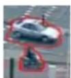
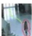
Objects that generate an alarm event under the current settings appear on the camera image inside a red outline.
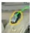
An object that has triggered one alarm event but does not generate another appears inside an orange outline (example: object has crossed a line).
In the Archive Player program, an orange outline also appears around objects that will trigger an alarm event, but only if a relevant search has been carried out beforehand.
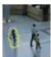
Objects that are detected as moving but do not generate an alarm event under the current settings appear inside a yellow outline.
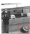
The point at which an object is detected as idle is displayed inside a frame and marked with an i (example: abandoned bag).
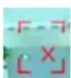
The point at which an object is detected as having been removed is displayed inside a frame and marked with an X (example: theft).
A green trajectory indicates the direction in which an object has moved.
Description
A yellow flag marks the currently selected object. The properties of this object can be displayed when a task is created.
An object can only be selected if you have selected the Object Properties tab (see: Section 4.8 Object Properties, page 47) or if you process the
Approximation (see: Section Next Step - Approximation, page 24) step when creating a task.
A flag with a blue head marks an object that has been detected by head detection (see: Section Final Step - Define the Head Detection Conditions, page 29).
4.3 IVA 4.0 User Interface
The following descriptions and screenshots relate to the user interface as it appears in Configuration Manager.
All tabs are combined in a dialog box in the Web browser view. The preview on the VCA configuration page is used as the camera image.
The configuration options are identical.
To open the online Help for IVA 4.0 click the area you are interested in and press F1.
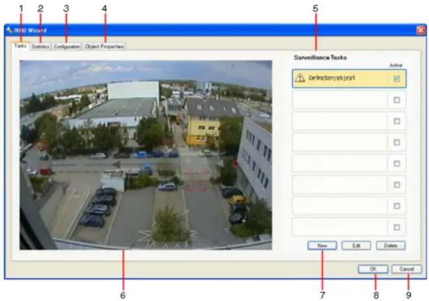
1 T a s k s
When this tab is selected, you can see all the defined tasks. You have the option to create new tasks and to edit or delete existing ones.
(See: Section 4.4 Tasks, page 22)
2 Statistics
When this tab is selected, the statistics for the individual fields are displayed.
(See: Section 4.6 Statistics, page 38)
3 Configuration
When this tab is selected, you can access all of the necessary basic settings:
- Calibration
(see: Section 4.7.1 Calibration, page 39)
- Global Settings
(see: Section 4.7.2 Global Settings, page 44)
- Sensitive Area
(see: Section 4.7.3 Sensitive Area, page 46)
4 Object Properties
The properties are displayed here for a marked object.
Object properties include:
- Object Size [^2]
- Aspect Ratio V/H
- Speed [km/h]
- Direction [°]
- Color
Changes to the object properties can be monitored here. In doing so, it is possible to detect whether an object has become faster, for example. Where possible, the displayed properties can also be used to check the calibration.
An object is marked by clicking in an object outline in the camera image, while this tab is displayed. The marked object is indicated by a yellow flag. Only one object can be marked at a time.
5 Depending on the tab selected, the following are displayed here:
- an overview of the defined tasks
– statistics on a selected field - tabs that provide access to all configuration settings
– the properties of a marked object
6 Camera image
The camera image is displayed irrespective of the tab selected.
If the Tasks tab is selected, the popup menu in the camera window, for example, enables fields, lines and routes to be created and changed.
(See: Section 4.3.1 Popup Menu in the Camera Image, page 19)
7 In this area, all the buttons are displayed that are required for work in the selected tab.
8 OK
This saves the settings for IVA 4.0 and closes the window.
Incomplete settings are not saved.
9 C a n c e l
The IVA Wizard is closed.
Any changes that were made after the IVA Wizard was launched and not saved to the device will be lost.

CAUTION!
Changes to task settings take effect immediately.
Configuration and tamper settings only take effect once they have been saved in Configuration Manager.
Settings are only saved permanently when you click in Configuration Manager or click
Save configuration in the Web browser view.
4.3.1 Popup Menu in the Camera Image
The popup menu in the camera image allows you to create, edit and delete fields, lines and routes. It gives you access to display options. You can also start the IVA Task Editor.
▶ Right-click in the camera image in order to display the popup menu.
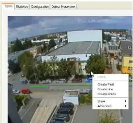
Depending on whether you click an object or free space, various commands are available. If the Statistics tab is selected, then no popup menu is available.
Overview of commands:
- Cut
If an item (field, line, route) is clicked, it is cut and copied to the clipboard using this command. You can also use the command to delete items.
Items integrated into a task cannot be cut or deleted.
- Copy
If an item (field, line, route) is clicked, it is copied to the clipboard using this command.
- Paste
An item (field, line, route) that has been copied to the clipboard is inserted using this command.
- Create Field
Creates a new field. The field can then be edited.
- Create Line
Creates a new line. The starting point is the point where you clicked. You set the end point by clicking at the desired position again. The line can then be edited.
- Create Route
Creates a new route. The starting point is the point where you clicked. Click other points in the camera image in order to specify the course of the route. Double-click to mark the end point. The route can then be edited.
- Show
From the submenu, select the items to be displayed in the camera image:
- Sensitive Area
The area marked as sensitive is shaded in yellow.
(See: Section 4.7.3 Sensitive Area, page 46)
- Object Outlines
Objects that are detected as moving are highlighted with a yellow outline. A red line indicates an object that has triggered an alarm event.
- Object Bounding Boxes
The object bounding box is the rectangle enclosing the object.
- Items
Hide fields, lines and routes where necessary.
- Trajectories
Hide the green line tracing the path of objects where necessary.
- Head Detection Flag
Objects that are detected by head detection can be marked as such.
- Insert Node
This menu option is only active if you have clicked a field frame or a route. This inserts a new node at this position.
Nodes can be repositioned as required using the mouse.
- Delete Node
If you have clicked a node, it is deleted using this command.
- Advanced > IVA Task Editor
The IVA Task Editor shows all items, tasks and connectives in script form. This option is only designed for users who are familiar with the IVA Task Script Language (see:
Section 4.3.2 The IVA Task Editor, page 22).
Editing a Field
A field can be edited at any time. This includes:
- Inserting or deleting nodes
| - | M | o | v | i | n | g | n | o | d | e | s |
| - | M | o | v | i | n | g | f | i | e | l | d |
To change the form of the field, place the mouse cursor on a node or a line and move it while holding down the mouse button. To move the field, place the mouse cursor in the field and drag it while holding down the mouse button.
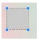
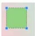
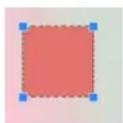
A field that is not being used in any tasks is displayed in gray.
A field that is being used in a task is displayed in green. Used fields can be edited but not deleted.
A field for which there is currently an alarm event is displayed in red.
Editing a Line
A line can be edited at any time. This includes:
- Moving end points
- Moving lines
To change the line, place the mouse cursor on an end point and move it while holding down the mouse button. To move the line, place the mouse cursor on the line and move it while holding down the mouse button. If a line is integrated into a task, you can choose the direction in which the line must be crossed in order to trigger an alarm.
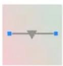
A line that is not being used in any tasks is displayed in gray.
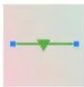
A line that is being used in a task is displayed in green. Used lines can be edited but not deleted.
The triangle marks the direction in which an object must cross a line in order to generate an alarm event. If an alarm event is generated each time the line is crossed, regardless of the direction, no arrow is displayed.
Editing a Route
A route can be edited at any time. This includes:
- Inserting or deleting nodes
- M o v i n g n o d e s
- Changing the tolerance range
- M o v i n g r o u t e s
A route is displayed as a line with an assigned direction. The line includes a tolerance range, which is displayed as an area. The tolerance range is axis-symmetric to the respective section of the central line. An extension to the tolerance range can be individually defined at any node.
To change the course of the route, place the mouse cursor on a node and move it while holding down the mouse button. To change the tolerance range, place the mouse cursor on the marking next to a node and move it while holding down the mouse button. To move the route, place the mouse cursor on the route and move it while holding down the mouse button. If a route is integrated into a task, you can select the direction in which movement along the route must trigger an alarm.
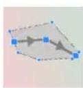
A route that is not being used in any tasks is displayed in gray.
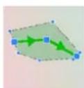
A route that is being used in a task is displayed in green. Used routes can be edited but not deleted.
The triangle marks the direction in which an object must follow the path in order to generate an alarm event. If an alarm event is generated each time there is movement along the route, regardless of the direction, no arrow is displayed.
4.3.2 The IVA Task Editor
The IVA Task Editor offers access in script form to the total configuration of the Video Content Analysis you have created. All items (fields, lines, routes) and all tasks are displayed using the IVA Task Script Language.

NOTICE!
Only change the script if you are familiar with the IVA Task Script Language. You can find the relevant documentation on the IVA 4.0 CD.
Creating a Backup with the IVA Task Editor
- Select Advanced > IVA Task Editor in the camera image popup menu.
- Right-click in the script window of the IVA Task Editor.
You will see the popup menu. - Select Save As.
-
Select a storage location and a name for the file. The file is saved in text format with the extension .evl. This saves the VCA configuration for this device in Configuration Manager.
-
Click in-Configuration Manager to save the VCA configuration to the device.
Recreating the Saved Configuration
- If necessary, first create a backup of the current configuration.
- Right-click in the script window of the IVA Task Editor. You will see the popup menu.
- Select Load.
- Select a file. The VCA configuration stored in this file is recreated.

CAUTION!
When a saved configuration is loaded, the existing configuration is overwritten. The procedure cannot be reversed once the configuration has been saved to the device by clicking
4.4 Tasks
This tab is displayed when you click Configuration... in the VCA tab in Configuration Manager. Before you define tasks, you should have performed the following steps:
- Section 4.7.1 Calibration, page 39 The speed, size and direction of movement of objects can only be correctly defined when IVA 4.0 is calibrated.
- Section 4.7.2 Global Settings, page 44 Among other things, objects can be generally excluded from the detection on the basis of their size.
- Section 4.7.3 Sensitive Area, page 46 Movements can only be detected and analyzed within the sensitive area.
Each of these settings can be changed at any time.
Overview
A task describes events that trigger an alarm event when detected in the camera image. Examples of typical events:
- An object moves within a defined area.
- An object crosses one or more lines, for example an automobile drives into a parking space.
- An object stops in certain areas without any target-specific movement (loitering).
- An object moves along a defined route.
- A piece of luggage is set down (idle object).
- An object is removed (theft).
- The camera is tampered with.
Some of the tasks, such as head detection and the identification of similar objects are primarily used for forensic searches on recordings.
The result of a task is an alarm event. An alarm event can be analyzed in a CCTV system in many ways. In this way, a recording can be started, a door closed or an e-mail sent, for example.
To edit a task, you must first highlight it. To do this, click the task. A highlighted task is outlined in blue.
To create and edit a task, you are guided step-by-step through the necessary settings. You can define up to eight tasks.
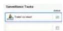
You can see the task list on the right-hand side of the window.
Select a task and then click the name of the task directly in order to change it.
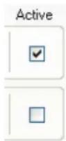
A task can be Active, i.e. an alarm event is generated. A task that is not active does not generate an alarm event.
Click the box next to the name of the task in order to activate it. An active task is indicated by a checkmark.
A task has an orange background if an alarm event is currently being triggered by this task.
A symbol in front of the task name indicates the type of task. The symbol corresponds to the symbol of the wizard that created the task.
New
Click here to create a new task. Instead of the task list, the window for selecting a wizard is displayed.
Edit
Click here to edit a selected task. The wizard that was displayed for the creation of the task is reopened. You can change individual parameters.
Delete Click here to delete a selected task.
4.5 Creating/Editing a Task
A task is always created or edited using a wizard.
The following wizards are available:
- Section 4.5.2 Object in field, page 24
An object moves within a defined field.
– Section 4.5.3 Crossing line, page 30
An object crosses one or more lines, for example an automobile drives into a parking space. - Section 4.5.4 Loitering, page 31
An object stops in a defined field without any target-specific movement.
– Section 4.5.5 Condition change, page 32
An object changes its state, for example, a person slips and falls.
– Section 4.5.6 Following route, page 33
An object moves along a defined path.
– Section 4.5.7 Tampering, page 34
The camera is tampered with.
- Section 4.5.8 Removed object, page 35
A previously idle object disappears, for example, in the event of theft.
- Section 4.5.9 Idle object, page 35
A previously moving object is at rest, for example, a piece of luggage is set down.
- Section 4.5.10 Entering field, page 36
An object enters a defined field.
– Section 4.5.11 Leaving field, page 36
An object leaves a defined field.
- Section 4.5.12 Similarity search, page 37
An object is detected that is similar to a previously classified object.
When you use the wizard to create or edit a task, you have access to the camera image and the popup menu. This means that you can create, edit or delete fields, lines or routes.
In Configuration Manager, the camera image with the popup menu is directly integrated into the IVA 4.0 window. When configuring in the Web browser view, you use the preview on the VCA configuration page.
You can immediately recognize from the color of object outlines whether an object will trigger an alarm with the given settings.
- Click Next to go to the next step of the wizard.
- Click Previous to go to the previous step of the wizard.
- If you want to skip any further steps, click Finish. The presets are adopted for any unedited steps.
You can change any settings again at any time.
4.5.1 Default Task
When you work with IVA 4.0 for the first time, the default task Detect any object is already available. This task detects all objects in the entire camera image. Initially, even the global settings are preset in such a way that no object is excluded.
This first preset task corresponds in the configuration to the task type Object in field (see: Section 4.5.2 Object in field, page 24).
4.5.2 Object in field

This task generates an alarm event if an object moves within a certain area. The area is defined by a field in the camera image.
First Step - Define the Field
- Select one of the fields.
To do this, use the list field or click a field in the camera image.
You can also create a new field, edit an existing one or select Whole screen.
2. Debounce time [s]
If a value other than 0 (zero) is selected, the alarm event will not be generated until the object has moved or been within the field for the specified period at least.
By entering a value, you can prevent the triggering of multiple alarm events by objects that are constantly moving toward and away from the boundary of the field.
Next Step - Approximation
You can impose approximations for the different object properties. You can adopt these values as the basis for the settings in the next step.
- Click a moving object in the camera image. The object is marked with a yellow flag. The properties of the marked object are displayed in the wizard.
The properties of an object are always changing. You adopt the properties of the object at the time of clicking.
The values for object size, aspect ratio, speed and direction are displayed for the marked object. The colors of the object are also displayed in proportional sequence.
-
If you want to use the properties of the marked object, activate the Apply values option.
-
For each of the properties, select how exactly they must correspond for an object to be detected as an object with these properties.
The Precision slide control sets the accuracy progressively.
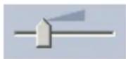
- Slide control set to the left:
Property is ignored.
The value is not adopted in the next step.
- Slide control set almost to the left:
Property is considered, correspondence can be very inaccurate.
- Slide control set to the right:
Property is considered, correspondence must be very accurate.
The further to the right the slide control is set, the more accurate the description of the property of the searched object that is to trigger an alarm.
For Object size [m^2] , Aspect ratio v/h, Speed [km/h] and Direction, the range of the displayed minimum and maximum values in the next step will be smaller the further to the right the slide control is set.
All adopted values can still be manually changed in the next step.
Next Step - Define the Conditions
Here you can precisely limit the properties of an object that triggers an alarm event. Objects that do not correspond to the properties specified here do not trigger an alarm event.
A property is used to search for an object if you activate the relevant option.
Options that have adopted the values from the previous step are automatically activated.
After an option has been activated, graphical support is provided in the camera image, which visualizes the object description. You can change the values for limiting the object properties in the camera image using the graphics, or also by entering the corresponding numeric values.
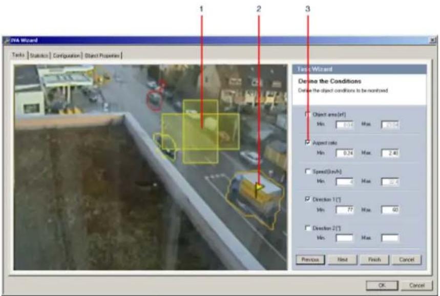
1 Visualization of the property
In this example, the visualization of the aspect ratio is displayed.
2 Marked object
The marked object whose properties are described is marked with a yellow flag.
3 Property activated
In this example, the Aspect ratio v/h property is used to describe an object.

NOTICE!
You can switch to the Object Properties tab at any time (see: Section 4.8 Object Properties, page 47). There you will find information on how the properties of the marked object change.
Object size [^2]
Only objects whose size (the area covered) corresponds to the entered values generate an alarm event.
▶ Enter a minimum and a maximum value for the size.
Aspect ratio v/h
Objects whose aspect ratio corresponds to the entered values generate an alarm event.
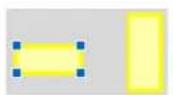
The minimum and maximum ratios are graphically displayed in the camera image as two yellow rectangles. By default, values are set with which all objects trigger an alarm event. You can change the values by
- entering the figures in the fields
or
- highlighting a rectangle in the camera image and dragging it to a node while holding down the mouse button.
The ratio is the quotient of the vertical and horizontal extension of the object in the image captured by the camera. The actual aspect ratio can deviate from this.
Persons captured directly from above always have the same aspect ratio in the image, irrespective of their actual size.
The aspect ratio of a person changes if the person falls down or stands up, for example. The aspect ratio of a vehicle changes if it changes its direction by 90^ .
Speed [km/h]
Only objects moving at a speed that corresponds to the entered values generate an alarm event.
▶ Enter a minimum and a maximum value for the speed.
![BOSCH IVA 4.0 - Speed [km/h] - 1](/content/2026/05/1052412/images/755bd79cd1d35732654994dfe75cce72538ad0117f25f05802c5d128a3fb3663.jpg)
NOTICE!
The speed of a movement at a right angle to the camera can be determined much more accurately than the speed of a movement directly toward or away from the camera.
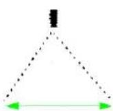
Object moves at a right angle to the camera: speed is detected more accurately
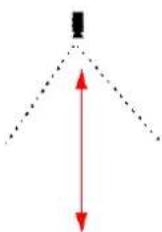
Object moves in camera's line of sight: speed is detected less accurately
Direction 1 [°] / Direction 2 [°]
![BOSCH IVA 4.0 - Direction 1 [°] / Direction 2 [°] - 1](/content/2026/05/1052412/images/0779c5107e62063aebe6a7158871998c692d9fe1b650ae0c5480a7c6d3a52b55.jpg)
Only objects moving in a certain direction generate an alarm event. The direction is determined by entering an angle.
![BOSCH IVA 4.0 - Direction 1 [°] / Direction 2 [°] - 2](/content/2026/05/1052412/images/0f45b08c711eebb310237af76850c63952b2efcd4ed2c5147703224e2fb7fc44.jpg)
0^ corresponds to the direction of movement from right to left.
It is counted counter-clockwise.
Another direction can be optionally entered. In this way, movements are captured in two directions.
The direction is graphically displayed by a yellow circle segment in the camera image.
You can change the values by
- entering the figures in the fields
- moving the yellow circle segment while holding down the mouse button in order to redefine the direction of movement or
- placing the mouse cursor over one of the edges of the circle segment and moving it while holding down the mouse button in order to change the direction tolerance.
![BOSCH IVA 4.0 - Direction 1 [°] / Direction 2 [°] - 3](/content/2026/05/1052412/images/499afc3b23f6944e65e361e87973640808469eb6e2e63ece67a63b29f6adacce.jpg)
NOTICE!
Only use the speed and direction filters for detecting truly significant movements; select your settings to ensure the most robust results possible.
Next Step - Define the Color
In this step, you describe the color property of the searched object.
Colors are described in IVA 4.0 using the HSV color model.
- H - Hue
The hue is the color that is reflected from an object. The hue is measured as a position on the color wheel and is given as a value between 0^ and 360^ .
- S - Saturation
The saturation is the intensity of the color. It describes the percentage of gray in relation to the hue and is measured as a percentage value between 0% (gray) and 100% (full saturation).
- V - Value
The value is the relative degree of brightness or darkness of the color and is measured as a percentage value between 0% (black) and 100% (white).
In this step, select the colors that describe the searched object, and determine how accurately the colors must match the object colors.
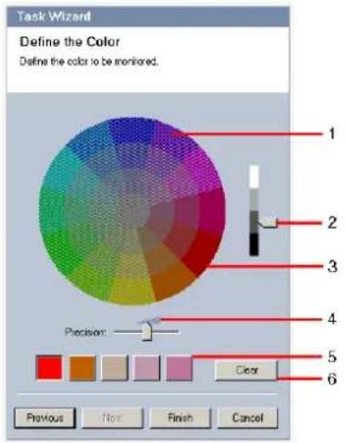
1 Color cylinder
All colors can only be displayed in 3D. In the illustration, you see a color cylinder from above, in which the saturation fades from the exterior to the interior and the value fades from the top to the bottom.
In the color wheel, the tones displayed unshaded are the ones that are to be taken into account in the search for objects for the marked color (5), in consideration of the precision (4).

NOTICE!
The graphic displays the maximum spectrum that is taken into account. If several colors are selected, this spectrum is only taken into account in full if the other colors correspond exactly to their individual definitions. The greater the deviation, the narrower the spectrum that is actually taken into account for the individual colors in the search.
2 Value
Use this slide control to select the degree of brightness for the colors. The number of colors to be taken into account is displayed according to the other settings. The display shows a higher or lower section of the color cylinder according to the slide control setting.
3 Colors
You can manually adopt colors from the color cylinder for the search. To do this, set the value first and then click the desired color segment using the mouse. Empty color squares are populated from left to right using the selected colors. You can change the colors by selecting a square and clicking another color from the color cylinder.
4 P r e c i s i o n
The precision is set progressively.
- Slide control set to the left:
Color is ignored.
- Slide control set almost to the left:
Color is considered, correspondence can be very inaccurate.
- Slide control set to the right:
Color is considered, correspondence must be very accurate.
The setting applies to all defined colors.
5 You can determine up to five hues that are displayed in the squares below the color wheel. The further left the selected color is arranged in the squares, the higher its proportion of the object's color properties. If you have set the color properties of an object to accept in the Approximation window, then these colors are automatically displayed here. Some of the color fields may be grayed out. This means that in the marked object, fewer than five colors have been detected.
6 Clear color
You can delete a color, for example if the hue relates to an object's background.
Simply highlight the color and click Clear. If there are colors on the right of the deleted position, then they will move up automatically and receive a higher proportion of the object's color properties.
Final Step - Define the Head Detection Conditions
In this step, you define whether an alarm should be triggered according to whether or not detected objects have a head. This enables you to set the surveillance to focus on people or exclude them completely.
Prerequisite
If you have not yet activated Head detection under Global Settings, you will receive a message to that effect. You will then be given the option to change this setting directly. To save on computing power, do not set the maximum values under Global Settings any higher than required for the task. For more details, refer to: Section Head Detection, page 45.
Use head detection filter
- Activate this option if you wish to filter objects based on head detection.
- Select one of the options:
- Limit to objects where no head has been detected
Alarm events are only triggered for objects on which no head is detected.
- Limit to objects with a largest head width between
Triggers an alarm event for objects on which a head of the specified size has been detected. The alarm event is generated during the period in which the object is within the detection area.
To determine the size of the heads, two head outlines representing the minimum and maximum head size are displayed in the camera image.
The outlines can be repositioned. The positioning of the outlines on the area of the image does not affect alarm generation.
Adjust the size of the outlines with the mouse or enter numbers between 8 (Min.) and 33 (Max.).
4.5.3 Crossing line

This task generates an alarm event if an object crosses one or more virtual lines.
First Step - Define the Lines
- Select from the list field one of the lines that have already been created or click a line in the camera image.
You can now also create a new line or edit an existing one.
- Select a second and a third line, if necessary.
3. Debounce time [s]
If a value other than 0 (zero) is selected, the alarm event will not be generated until the object has been on the other side of the line for the specified period at least.
By entering a value, you can prevent the triggering of multiple alarm events by objects that are constantly moving onto and away from the line.
This entry always relates to the line currently highlighted in this dialog box. Where necessary, this entry must be repeated for each line.
4. Direction
Select for the highlighted line whether the alarm should be triggered if the line is crossed according to the direction of the arrow in the graphic display (Forward), against this direction (Backward) or independently of the direction (Any).
The display of the direction is adapted accordingly in the camera image.

NOTICE!
The change in the alarm-triggering direction is adopted for all tasks using this line.
Next Step - Define the Trigger
This step is only displayed if at least two lines are used for this task.
Here, you specify whether the corresponding crossings generate an alarm event independently of one another or whether the lines must be crossed in a pre-defined sequence and, if necessary, at a defined time interval.
- Activate the required option.
- Enter a minimum and a maximum value if an alarm event should only be triggered if the crossing is within a pre-defined time span.
Next Step - Approximation
You can impose approximations for the different object properties. You can adopt these values as the basis for the settings in the next step.
These settings are described here: Section Next Step - Approximation, page 24.
Next Step - Define the Conditions
You limit the number of objects that trigger an alarm event by precisely defining properties such as size, aspect ratio, speed and direction.
These settings are described here: Section Next Step - Define the Conditions, page 25.
Note: Approximations cannot be used for the Crossing line task.
Next Step - Define the Color
You limit the number of objects that trigger an alarm event by defining the color properties more precisely.
These settings are described here: Section Next Step - Define the Color, page 28.
Final Step - Define the Head Detection Conditions
In this step, you define whether an alarm should be triggered according to whether or not detected objects have a head. This enables you to set the surveillance to focus on people or exclude them completely.
These settings are described here: Section Final Step - Define the Head Detection Conditions, page 29.
4.5.4 Loitering

This task generates an alarm event if an object only moves slightly within a certain area for a specified period. The area is defined by a field in the camera image.
First Step - Define the Field
- Select one of the fields.
To do this, use the list field or click a field in the camera image.
You can also create a new field, edit an existing one or select Whole screen.
2. Debounce time [s]
If a value other than 0 (zero) is selected, the alarm event will not be generated until the object has moved or been within the field for the specified period at least.
By entering a value, you can prevent the triggering of multiple alarm events by objects that are constantly moving toward and away from the boundary of the field.
Next Step - Define the Trigger
An alarm is generated if an object only moves within the tolerance area during a time span. As soon as an object is detected in the sensitive area, a virtual circle corresponding to the tolerance area is placed around the object. If the object does not leave this tolerance area during the specified time and the object remains in the monitored field, an alarm is triggered. If the object leaves the tolerance area during the specified time, a new virtual circle is defined around the current position and the measurement of time starts again.
- Radius [m]
Here you can specify the size of the circle that the object must not leave for it to be detected as loitering.
- Time [s]
This specifies the period of time in seconds during which the object must remain within the virtual circle.
Final Step - Define the Head Detection Conditions
In this step, you define whether an alarm should be triggered according to whether or not detected objects have a head. This enables you to set the surveillance to focus on people or exclude them completely.
These settings are described here: Section Final Step - Define the Head Detection Conditions, page 29.
4.5.5 Condition change

This task generates an alarm event if one of the following properties changes for a detected object within a specified time span:
- Size
- Aspect ratio
- S p e e d
- D i r e c t i o n

NOTICE!
Only activate the properties that should be analyzed for this task.
If you activate multiple properties, then all of these object properties must change for an alarm event to be triggered (logical connective = AND).
If an alarm is to be triggered when multiple properties are changed independently of one another, you must only create one dedicated task for each of these properties.
First Step - Define the Initial Conditions
Define individual properties, such as the size, aspect ratio, speed and direction, that an object must have in its initial condition for it to be detected.
These settings are described here: Section Next Step - Define the Conditions, page 25.
Next Step - Define the Trigger
For the properties defined in the previous step, specify which values will trigger an alarm event.
These settings are described here: Section Next Step - Define the Conditions, page 25.
Next Step - Define the Time Span
Here you can limit the time span in which the change in the selected properties takes place.
- Activate the option.
- Enter a minimum and maximum value in seconds.
The time span will only be analyzed when you activate this option. If this option is not activated, respective changes in an object property will trigger an alarm event regardless of the length of time that has passed.
Next Step - Define the Field
You can limit the detection of changes to a specific area. The area is defined by a field in the camera image.
- Select one of the fields.
To do this, use the list field or click a field in the camera image.
You can also create a new field, edit an existing one or select Whole screen.
2. Debounce time [s]
If a value other than 0 (zero) is selected, the alarm event will not be generated until the object has moved or been within the field for the specified period at least.
By entering a value, you can prevent the triggering of multiple alarm events by objects that are constantly moving toward and away from the boundary of the field.
Final Step - Define the Head Detection Conditions
In this step, you define whether an alarm should be triggered according to whether or not detected objects have a head. This enables you to set the surveillance to focus on people or exclude them completely.
These settings are described here: Section Final Step - Define the Head Detection Conditions, page 29.
4.5.6 Following route

This task generates an alarm event if an object moves along a certain route. A route is surrounded by a virtual tolerance area.

NOTICE!
This task is typically used in the Archive Player program for forensic searching. For example, persons who have taken a certain route are detected this way.
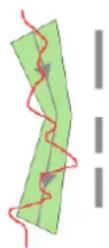
First Step - Define the Route
- Select from the list field one of the routes that have already been created or click a route in the camera image.
You can now also create a new route or edit an existing one.
- Define the properties of the selected route.
- Min. match [%]
Enter a value in percent here. An object must have moved along the route for this percentage of the total distance.
The value indicates the overall proportion of the route. An object must not necessarily cover this percentage of a section in a single stage in order to trigger an alarm event.
![BOSCH IVA 4.0 - - Min. match [%] - 1](/content/2026/05/1052412/images/73c1d997d9ffe1bd2a32564c1895856ac23770710c42416c2dcff200c46221cc.jpg)
- Max. gap [%]
Enter a value in percent here.
The value indicates the percentage of the largest gap in the total section.
If the object leaves the route for a section that corresponds to this percentage at the least, no more alarm events will be triggered.
- Direction
Select whether an alarm should be triggered if the route is followed according to the direction of the arrow in the graphic display (Forward), against this direction
(Backward) or independently of the direction (Any).
The display of the direction is adapted accordingly in the camera image.

NOTICE!
The change in the alarm-triggering direction is adopted for all tasks using this route.
Next Step - Approximation
You can impose approximations for the different object properties. You can adopt these values as the basis for the settings in the next step.
These settings are described here: Section Next Step - Approximation, page 24.
Next Step - Define the Conditions
You limit the number of objects that trigger an alarm event by precisely defining properties such as size, aspect ratio, speed and direction.
These settings are described here: Section Next Step - Define the Conditions, page 25.
Next Step - Define the Color
You limit the number of objects that trigger an alarm event by defining the color properties more precisely.
These settings are described here: Section Next Step - Define the Color, page 28.
Final Step - Define the Head Detection Conditions
In this step, you define whether an alarm should be triggered according to whether or not detected objects have a head. This enables you to set the surveillance to focus on people or exclude them completely.
These settings are described here: Section Final Step - Define the Head Detection Conditions, page 29.
4.5.7 Tampering

This task generates an alarm event if it must be assumed that the video source (camera) has been tampered with.
Here, you can only activate the filter for the relevant events. You cannot alter the settings for tamper detection. Only the settings from the standard configuration page apply.
An alarm event is generated if one of the activated events occurs (logical connective = OR).
- Global change
Activate this function if the global change, as set with the Global change slide control on the standard configuration page, should trigger an alarm.
- Scene too bright
Activate this function if tampering associated with exposure to extreme light (for instance, shining a flashlight directly on the lens) should trigger an alarm. The average brightness of the scene provides a basis for recognition.
- Scene too dark
Activate this function if tampering associated with covering the lens (for instance, by spraying paint on it) should trigger an alarm. The average brightness of the scene provides a basis for recognition.
- Scene too noisy
Activate this function if tampering associated with EMC interference (noisy scene as the result of a strong interference signal in the vicinity of the video lines), as an example, should trigger an alarm.
- Signal loss
Activate this function if the interruption of the video signal should trigger an alarm.
- Reference check
Activate this function if a deviation from the reference image on the standard configuration page should trigger an alarm.
4.5.8 Removed object

This task generates an alarm event if an object is detected as removed in a certain area (for example, due to theft). The area is defined by a field in the camera image.
It is assumed that an object has been removed if changes are detected in the background following movement within an image.
First Step - Define the Field
▶ Select one of the fields.
To do this, use the list field or click a field in the camera image.
You can also create a new field, edit an existing one or select Whole screen.
Next Step - Approximation
You can impose approximations for the different object properties. You can adopt these values as the basis for the settings in the next step.
These settings are described here: Section Next Step - Approximation, page 24.
Next Step - Define the Conditions
You limit the number of objects that trigger an alarm event by precisely defining properties such as size, aspect ratio, speed and direction.
These settings are described here: Section Next Step - Define the Conditions, page 25.
Final Step - Define the Color
You limit the number of objects that trigger an alarm event by defining the color properties more precisely.
These settings are described here: Section Next Step - Define the Color, page 28.
4.5.9 Idle object

This task generates an alarm event if an object is detected as idle or inserted in a certain area (for example, a piece of luggage without an owner). The area is highlighted by a field in the camera image.
First Step - Define the Field
- Select one of the fields.
To do this, use the list field or click a field in the camera image.
You can also create a new field, edit an existing one or select Whole screen.
2. Debounce time [s]
This entry is adopted from the global settings.
Next Step - Approximation
You can impose approximations for the different object properties. You can adopt these values as the basis for the settings in the next step.
These settings are described here: Section Next Step - Approximation, page 24.
Next Step - Define the Conditions
You limit the number of objects that trigger an alarm event by precisely defining properties such as size, aspect ratio, speed and direction.
These settings are described here: Section Next Step - Define the Conditions, page 25.
Final Step - Define the Color
You limit the number of objects that trigger an alarm event by defining the color properties more precisely.
These settings are described here: Section Next Step - Define the Color, page 28.
4.5.10 Entering field

This task generates an alarm event if an object enters an area. The area is highlighted by a field in the camera image.
The alarm event is triggered if an object that was previously detected outside a field crosses the field boundary.
First Step - Define the Field
- Select one of the fields.
To do this, use the list field or click a field in the camera image.
You can also create a new field, edit an existing one or select Whole screen.
2. Debounce time [s]
If a value other than 0 (zero) is selected, the alarm event will not be generated until the object has moved or been within the field for the specified period at least.
By entering a value, you can prevent the triggering of multiple alarm events by objects that are constantly moving toward and away from the boundary of the field.
Next Step · Approximation
You can impose approximations for the different object properties. You can adopt these values as the basis for the settings in the next step.
These settings are described here: Section Next Step - Approximation, page 24.
Next Step - Define the Conditions
You limit the number of objects that trigger an alarm event by precisely defining properties such as size, aspect ratio, speed and direction.
These settings are described here: Section Next Step - Define the Conditions, page 25.
Next Step · Define the Color
You limit the number of objects that trigger an alarm event by defining the color properties more precisely.
These settings are described here: Section Next Step - Define the Color, page 28.
Final Step - Define the Head Detection Conditions
In this step, you define whether an alarm should be triggered according to whether or not detected objects have a head. This enables you to set the surveillance to focus on people or exclude them completely.
These settings are described here: Section Final Step - Define the Head Detection Conditions, page 29.
4.5.11 Leaving field

This task generates an alarm event if an object leaves an area. The area is highlighted by a field in the camera image.
The alarm event is triggered if an object that was previously detected inside a field crosses the field boundary.
First Step - Define the Field
- Select one of the fields.
To do this, use the list field or click a field in the camera image.
You can also create a new field, edit an existing one or select Whole screen.
2. Debounce time [s]
If a value other than 0 (zero) is selected, the alarm event will not be generated until the object has moved or been outside the field for the specified period at least.
By entering a value, you can prevent the triggering of multiple alarm events by objects that are constantly moving toward and away from the boundary of the field.
Next Step - Approximation
You can impose approximations for the different object properties. You can adopt these values as the basis for the settings in the next step.
These settings are described here: Section Next Step - Approximation, page 24.
Next Step - Define the Conditions
You limit the number of objects that trigger an alarm event by precisely defining properties such as size, aspect ratio, speed and direction.
These settings are described here: Section Next Step - Define the Conditions, page 25.
Next Step - Define the Color
You limit the number of objects that trigger an alarm event by defining the color properties more precisely.
These settings are described here: Section Next Step - Define the Color, page 28.
Final Step - Define the Head Detection Conditions
In this step, you define whether an alarm should be triggered according to whether or not detected objects have a head. This enables you to set the surveillance to focus on people or exclude them completely.
These settings are described here: Section Final Step - Define the Head Detection Conditions, page 29.
4.5.12 Similarity search

This task generates an alarm event if an object is detected that is similar to a previously marked object.

NOTICE!
This task is typically used in the Archive Player program for forensic searching. For example, persons who are similar to a certain person are detected this way.
Approximation
-
Click a moving object in the camera image. The object is marked with a yellow flag.
The properties of an object are always changing. You adopt the properties of the object at the time of clicking. -
Specify the approximations for the different object properties.
-
For each of the properties, select how exactly they must correspond for an object to be detected as being similar to this object.
The Precision slide control sets the accuracy progressively.
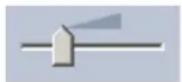
- Slide control set to the left:
Property is ignored.
- Slide control set almost to the left:
Property is considered, correspondence can be very inaccurate.
- Slide control set to the right:
Property is considered, correspondence must be very accurate.
The further to the right the slide control is set, the more accurate the description of the property of the searched object that is to trigger an alarm.
4.6 Statistics
When you select the Statistics tab, three histograms with statistics on the relevant detected objects are displayed on the right-hand side of the window, either for a selected field or for the whole screen. You can either select the field in the camera image by clicking it or click one of the tabs on the right-hand side of the window. A tab is shown here for the whole screen and for each respective field.
The statistics help you to refine the filter criteria for objects. For example, you may see accumulations of objects that have not triggered an alarm under the current filter criteria even though this might have been desirable.
The creation of the displayed statistics starts as soon as you open the IVA 4.0 window. The longer the window is left open, the more values will be entered into the statistics.
The statistics show three histograms:
- Object Area Histogram [^2] : accumulation of objects with a certain area.
- Object Speed Histogram [km/h]: accumulation of objects moving at a certain speed.
- Object Direction Histogram [°]: accumulation of objects moving in a certain direction.
The lines indicate the percentage of objects for which the respective value was detected. The higher the line, the more objects matched the particular criterion. The histograms distinguish between objects that trigger an alarm (red line) and those that do not (green line).
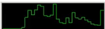
Green:
set of objects with no alarm
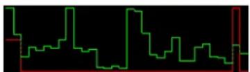
Red:
set of objects with alarm
The x-axis of the top two histograms (area, speed) automatically adapts.
Displayed as the highest value here is the highest detected value up to this point.
Click Reset to begin building statistics again.
4.7 Configuration
This tab provides access to basic settings that you should specify before defining the individual tasks:
- Section 4.7.1 Calibration, page 39
– Section 4.7.2 Global Settings, page 44
- Section 4.7.3 Sensitive Area, page 46
The settings and values defined here are valid for all tasks.
4.7.1 Calibration
Calibration is necessary for specifying the relationship between the camera image and the real-life environment. Areas and speeds can be correctly interpreted after the camera angle, camera elevation and distance are entered.
Calibration is required primarily so that the speed and size of detected objects or the radius of movement for loitering persons are correctly interpreted.
With a VG4 AutoDome, calibration must be completed for each preset.

NOTICE!
The unit of measurement display can be adapted so that when the English language user interface is used, the relevant "imperial measurements" used in the English-speaking world are displayed (see: Section 7 Display of Units of Measurement, page 59).
If you select the Calibration tab, the parameters with the currently set values are displayed on the right-hand side of the window.
IVA 4.0 allows two types of calibration:
- Section Calibrating with Calibration Elements, page 39
– Section Calibrating with Calibration Plane, page 42
Switch between the calibration types by clicking one of the buttons:

The system must be recalibrated each time the camera position is changed.
Calibrating with Calibration Elements
The calibration is defined by placing several calibration elements (lines and angles) on the camera image and adjusting these step by step in relation to the actual situation.
-
In the Camera section, enter all the values you know regarding the camera and its positioning:
-
Activate the Fixed option in each case.
- Then enter the corresponding value.
Tilt angle [°] The angle between the horizontal and the camera.
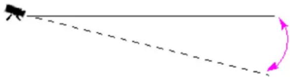
natural_image
Simple diagram showing a dashed line with an arrowhead and a curved arrowhead, no text or symbols present.The flatter the tilt angle is set, the less accurate the estimate of object sizes will be. Estimates are no longer possible when you have reached 0^ .
Roll angle [°] The angle by which the camera is tilted.
The setting can deviate from the horizontal by up to 10 degrees.
Elevation [m]
The vertical distance from the camera to the ground plane of the captured image – typically the elevation of the mounted camera above the ground.
![BOSCH IVA 4.0 - Elevation [m] - 1](/content/2026/05/1052412/images/17abe30db20db6c8211bf0a8ecafe6fa149eeb220dce2ca7abeaa69e05b81b81.jpg)
natural_image
Simple diagram showing a black object with an upward arrow and a dashed diagonal line extending from its top, no text or symbols present.Focal length [mm] This value can be found in the camera calibration.
Sensor size This value can be found in the camera calibration.
Sensor aspect ratio This value can be found in the camera calibration.
- Place at least two calibration elements on the camera image. Use these calibration elements to trace individual outlines of the displayed environment in the camera image and define the positioning and dimension of these lines and angles.
- Click, to place a vertical line across the image. A vertical line corresponds to a line that is perpendicular to the ground plane, such as a door frame, edge of a building or a lamp post.
- Click, to place a line across the ground in the image. A line on ground corresponds to a line that is on the ground plane, such as a road painting.
- Click, to place an angle on the ground in the image. The angle on ground represents an angle lying on the horizontal ground plane, such as the corner of a carpet or parking bay markings.
If you double-click a button, this will remain selected. This will enable you to draw several elements of the same kind without having to repeatedly select the button.
The number of required calibration elements is equal to the number of unspecified camera parameters plus one. At least one Vertical line and one Line on ground or one Angle on ground should have been created.
- Adjust the calibration elements to the situation:
- Click a line or an angle to highlight the element. The length of the line and/or angle is displayed underneath the buttons for the calibration elements. Adjust these values so that they correspond to the actual situation.
Example: You have placed a line on ground across the lower side of an automobile. You know that the automobile is 4 m long. Enter 4 m as the length of the line.
- Move the elements or element end points with the right mouse button held down. - Click Remove Element to delete the selected element.
Blue lines indicate calibration elements added by you.
White lines represent the element as it should be positioned on the camera image based on the current calibration results or the determined calibration data.
-
Click Adapt Elements, to adapt the calibration elements to the calibration results or the calibration data.
-
Click Calibrate to carry out calibration.
Calibration is carried out automatically when the calibration elements are moved.
The Quality: color field indicates the quality of the calibration:
- red: data conflicting or insufficient to complete a calibration.
- yellow: calibration is inaccurate.
- green: good quality calibration.
The Error color field indicates the deviation of the plotted calibration elements from the perceived actual situation.
- red: significant deviation.
- yellow: minimal deviation.
- green: length of the plotted lines and angles indicate the actual situation.
Once you have clicked Adapt Elements, the field will always be displayed in green.
The tooltip indicates the deviation of the elements you created from the suggested elements.
The smaller this value is, the better the calibration.
Horizon
If the values correspond, areas on the camera image have a colored background:
- blue: This area corresponds to the sky; the bottom line of the blue area represents the horizon. Objects that are detected in the blue area cannot be filtered correctly by size or speed.
- yellow: Objects that are smaller than 2 m and are in the area underneath the horizon cannot be detected as they are too small. If you wish to detect objects in this area, you must choose a different camera location.
If the camera is installed at a relatively low height in a building, for example, this display is not required, because the entire area covered by the camera is below the horizon.
Popup Menu
Right-click in the camera image to open the popup menu. The following commands are available here:
- Cut: Removes the highlighted element.
– Copy: Copies the highlighted element to the clipboard. - Paste: Reinserts a cut or copied element.
- Clear All: Deletes all elements.
- To Background: The highlighted element is moved to the background of the display. This allows you to highlight elements that were masked by the element.
– Hide Other Elements: Hides the elements that are not highlighted. - Display All Elements: Displays elements that had previously been hidden.
- Create Line on Ground: Corresponds to clicking

- Create Vertical Line: Corresponds to clicking .

- Create Angle on Ground: Corresponds to clicking on .

Verify
The calibration can be verified by changing the verify mode.
- Click Verify.
The button changes the labeling to Calibrate.
- Place elements on the camera image, as described previously.
The dimensions of the element are displayed underneath the buttons as they are determined by the calibration. These dimensions should correspond to reality, which means that a line that is 1 m long on the captured image will be displayed as 1 m in length.
- Click Calibrate to switch back to calibration mode.
Applying the Calibration
- Click Apply to save the calibration for this image.
- Click Cancel to return to the last saved calibration.
Calibrating with Calibration Plane
The calibration is defined by placing a virtual plane on the camera image and adjusting it step-by-step in relation to the actual situation.
With a VG4 AutoDome, calibration must be completed for each preset.
The settings are graphically displayed on the camera image by the virtual plane and two cubes.
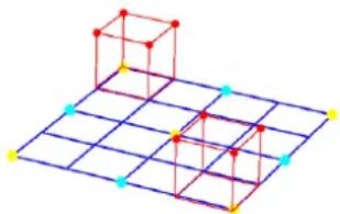
natural_image
3D geometric diagram showing two red cubes placed on a blue grid with colored dots at vertices (no text or symbols)The virtual plane appears as a blue grid and can be tilted, rotated and scaled. Position the virtual plane on the camera image so that it matches the angle and perspective of one of the actual horizontal areas. A section of a street is a suitable reference area, especially if the sides of the street are marked.
Two red cubes are displayed on the plane. In the default setting, the side length of one of these cubes is equivalent to 2 m – so the cube is about the same height as a person. The cubes are shown in the perspective of the blue plane.
You can adjust the position and size of the cubes - so that a cube corresponds to a car, for example.
- Position one of the red cubes over an object that you wish to trigger an alarm event.
- Adjust the cube to the size of this object. The second cube changes its size to suit the selected perspective.
- You can place the second cube over another object of the same type, for example a second person who is further back in the image. This allows you to check whether the perspective is set correctly.
The more care you take over calibration, the more accurately the size, direction and speed of moving objects can be estimated.
You can, of course, alter your settings at any time.
The system must be recalibrated each time the camera position is changed.
Adjusting the Calibration Plane
This section provides an overview of the ways in which the calibration plane can be adjusted. Move the mouse cursor over an anchor point or a line and then perform the required action while holding down the mouse button.
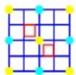
Start position At the beginning, the calibration plane is shown upright.
Anchor point center of a side line of the plane The calibration plane is scaled.
Anchor point center of the plane
The entire calibration plane is moved.
One of the lines of the plane that is horizontal in the start position
The calibration plane is tilted horizontally; the tilt angle is changed.
One of the lines of the plane that is vertical in the start position
The calibration plane is tilted vertically; the roll angle is changed.
Anchor point lower corner of the plane
The perspective of the calibration plane is distorted.
Anchor point upper corner of the plane
The calibration plane is rotated.
Anchor point corner of a cube The size of both cubes changes – both cubes always represent the same size.
Line of a cube The cube can be positioned as desired.
Editing Calibration Settings
You can also change the settings for each parameter by entering the relevant values.
Size [m] Side length of the cubes.
A side length of 2 m corresponds approximately to the height of a person.
Center Cubes
Both cubes are positioned centrally on the calibration plane.
Tilt angle [°] The angle between the horizontal and the camera.
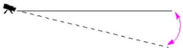
natural_image
Simple diagram showing a dashed line with an arrowhead and a curved arrowhead, no text or symbols present.The flatter the tilt angle is set, the less accurate the estimate of object sizes will be. Estimates are no longer possible when you have reached 0^ .
Roll angle [°] The angle by which the calibration plane is tilted.
The setting can deviate from the horizontal by up to 10 degrees.
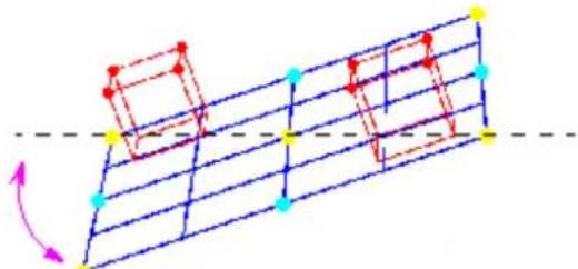
natural_image
Diagram showing a grid with colored blocks and arrows indicating direction (no text or symbols)Elevation [m]
The vertical distance from the camera to the ground plane of the captured image – typically the elevation of the mounted camera above the ground.
![BOSCH IVA 4.0 - Elevation [m] - 1](/content/2026/05/1052412/images/02dcaafee58d70be9200676762410f4b8f874eae8d9308719c3c33691c8de7e8.jpg)
natural_image
Simple diagram showing a person standing on a horizontal line with a dashed diagonal line and a pink upward arrow (no text or symbols)Focal length [mm] This value can be found in the camera calibration.
Sensor size This value can be found in the camera calibration.
Sensor aspect ratio This value can be found in the camera calibration.
Reset All settings are reset to their initial conditions.
Applying the Calibration
-
Click Apply to save the calibration for this image.
-
Click Cancel to return to the last saved calibration.
4.7.2 Global Settings
Certain objects can be globally excluded from detection using this tab. The computing power required can be reduced if objects that are categorically not to trigger an alarm event are not monitored.
Size Constraint
Here you can specify a minimum and maximum size for all objects that will generate an alarm event. Objects that are smaller or larger than the specified sizes will be ignored and this will save computing power as a result.
Initially, the global settings are preset in such a way that no object is excluded.
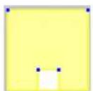
The values are simultaneously graphically displayed in the camera image by two yellow-framed squares. Drag one of the blue nodes to adjust the values. Using the mouse, the yellow squares can be moved in the camera image to cover objects being used for size comparison.
Make sure that the range between the minimum and maximum size is not too small, or relevant objects may be unintentionally eliminated from alarm generation.
Head Detection
- Activate this option if you wish to use head detection.
Two head outlines, representing the minimum and maximum size of the heads to be identified, will be displayed in the camera image.
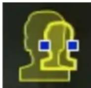
- Move one of the outlines onto a head that is displayed in the camera image and adapt the size
or
enter the corresponding values in the input fields.
Avoid false alarms and reduce required computing power by restricting head detection to the expected head sizes. If the required computing power is too high, heads can no longer be recognized.
For further details on using head detection as a filter in tasks, please see: Section Final Step - Define the Head Detection Conditions, page 29.
Notes on Finding Heads
An object is recognized as an object with a head if a shape resembling a head with colors that resemble human skin is detected. Head detection is only possible using a color camera. Heads will not be detected if the colors have been severely tampered with.
The best way to detect heads is if the camera captures them from the front and slightly from above. For optimum results, the height of the head should be approximately 10% of the height of the image. Individuals wearing large headdresses or that are only captured from the side will not be recognized as an object with a head.
Functions
- Idle object detection
Idle objects can only be detected if this option is activated.
An idle object is an object that was detected as an object based on an initial movement.
The object is then classed as idle if it does not move for the time span entered under
Debounce time [s].
- Debounce time [s]
Enter the time span in seconds for which an object must remain idle in order to be classed as such.
- Removed object detection
Removed objects can only be detected if this option is activated.
An object is assumed to have been removed if changes are detected in the background following movement within an image.
- Image stabilization
If you activate this option, the movement of the image (strictly speaking, the camera) is compensated by up to 2% of the image size.
Activate this option if the camera is mounted on an oscillating mast, for example.
- FIR camera
If you make these settings for a Far Infrared camera (FIR), activate this option so that objects can be correctly detected.
- Enhanced separation
- Activated: Improves the detection and separation of objects that move in close proximity to one another. This option requires additional computing power.
- Deactivated: Objects moving in close proximity to one another may blend into one object.
Advantages and disadvantages of the individual setting depend on the captured image.
Reset
Click here to reset all settings to their initial conditions.
Apply
Click here to apply all settings.
4.7.3 Sensitive Area
The sensitive area is that part of the image seen by the camera that is analyzed. Objects moving outside the sensitive area cannot generate an alarm event even if they are caught by the camera.
Only objects moving inside the sensitive area are detected as such and generate an alarm event – this also applies for the later evaluation of recordings in the Archive Player program. The larger the sensitive area, the more computing power is required. Data will be processed more slowly.
A smaller sensitive area means that data processing is faster.
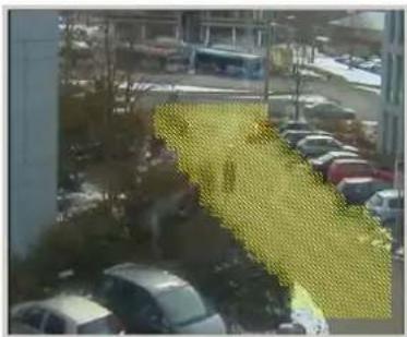
natural_image
Exterior view of a modern office building (no signage)The sensitive area is shown in yellow hatching.
In the default setting, the whole of the image captured by the camera is defined as the sensitive area. Any areas that consist of small squares can be defined as non-sensitive (or again as sensitive). There are four editing tools you can use for this purpose. You can repeat this operation as often as you like. You can therefore achieve a very precise definition of the sensitive area.
Examples of areas that could be defined as non-sensitive:
- Railroad:
Passing trains can trigger unwanted motion alarms.
- Public streets:
Passers-by moving across a public space should not be detected – in order to save unnecessary computing power and prevent unwanted false alarms.
- Neighboring properties:
Areas in which moving objects are not anticipated.
- S k y :
Birds or planes can trigger false alarms.
- Trees or bushes that move in the wind.
Tool Selection of an editing tool.
Rubber Band
You can use the mouse to draw any size of square.
Small Square
Medium Square
Large Square
You can edit the sensitive area as with a drawing tool.
Clear All
Click here to define the whole of the captured area as non-sensitive.
Set All Click here to define the whole of the captured area as sensitive.
Apply Click here to apply all settings.
While you are drawing, hold down the SHIFT key to create non-sensitive areas.
Drawing by itself without the SHIFT key marks out sensitive areas.
4.8 Object Properties
Selecting this tab allows you to monitor the properties of a marked object over a longer period of time and observe changes.
The properties of a moving object are always changing. An automobile does not always drive at a constant speed; a person sits down and stands up or changes direction.
The color of an object depends on the lighting of the image, for example. Different colors are detected under a floodlight than in the shade.
Using the values displayed here, you can estimate which minimum and maximum values you must enter for the creation of a task to ensure the desired objects are captured.
Furthermore, the values displayed help to check and refine an existing calibration. Implausible values indicate faulty calibration.
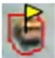
– Highlight an object in the camera image by clicking it.
The object is marked with a yellow flag.
- The properties of the object are displayed on the right-hand side of the window.
The numerical value for the property is updated every second while the object is marked. The progression graph displays the change in values of each property during the previous 30 seconds.
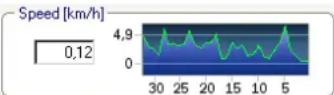
The Color property is not displayed using the numerical value and progression graph.
In the lowest field, the color properties of the marked object are displayed using color columns that are arranged according to their weighting. The further to the left a column is, the higher its proportion of the object's color property.
If you move the mouse cursor over one of the color columns, a tooltip displays the values for hue, saturation and value (HSV), as well as the weighting of the color.
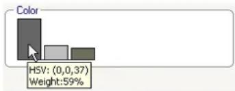
The illustration of the color columns is also updated once every second. It changes when the color property of the marked object changes.
Colors that appear as less than 5% are not displayed.
Colors cannot be detected for very small objects.

NOTICE!
If a marked object leaves the sensitive area, the properties can no longer be monitored. This also applies to objects that do not move for a longer period of time. The value display no longer changes if this is the case. If necessary, click another object.
5 IVA 4.0 Flow
This chapter provides a description of the program, the configuration and the various IVA 4.0 Flow settings.
5.1 The Basics and Image Information
The IVA 4.0 Flow approach differs from the IVA 4.0 object recognition. This function detects an optical flow formed by the movement of individual blocks. The camera does not need to be calibrated. The size of a detected object is irrelevant.
Depending on the IVA 4.0 Flow configuration, additional overlays in the image can provide further information.
Description
Red arrows indicate a detected flow that will generate an alarm event in accordance with the current settings.
Yellow arrows indicate a detected flow that will not generate an alarm event.
The arrows indicate the direction of movement of the detected block. The length of an arrow indicates the speed of the block. This ensures that movements that have been defined in more detail can be filtered out and will not trigger an alarm.
Flow Detection Notes and Limitations
If the computing power is reduced because of enhanced encoding power, fast speeds can no longer be detected.
Optimum flow detection is recorded at speeds of two to eight seconds (throughput time in the sensitive area). Very fast and slow movements are not detected as a flow.
Objects that are smaller than 1% of the image area do not trigger flow detection.
Textured objects that stand out from the background are more likely to be detected than those that are similar.
Objects that move backward and forward or move in a zig zag do not trigger flow detection.
An object can only trigger flow detection if it predominantly moves in a straight line. However, if objects are temporarily concealed by a tree, for example, detection is not restricted.
5.2 IVA 4.0 Flow User Interface
The following descriptions and screenshots relate to the user interface as it appears in Configuration Manager.
All tabs are combined in a dialog box in the Web browser view. The preview on the VCA configuration page is used as the camera image.
The configuration options are identical.
▶ To open the online Help for IVA 4.0 click the area you are interested in and press F1.
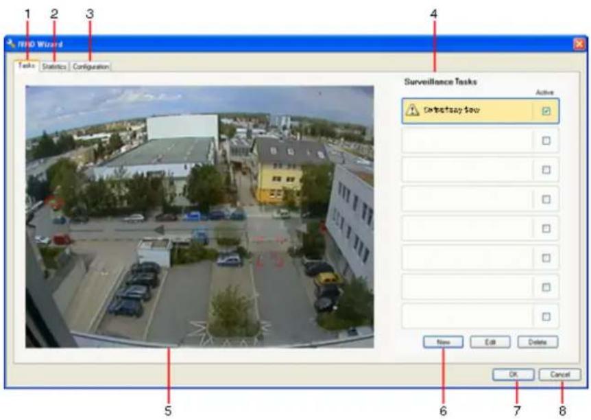
1 T a s k s
When this tab is selected, you can see all the defined tasks. You have the option to create new tasks and to edit or delete existing ones.
(See: Section 5.3 Tasks, page 52)
2 Statistics
When this tab is selected, the statistics for the detected flows are displayed. (See: Section 5.5 Statistics, page 56)
3 Configuration
When this tab is selected, you can access all of the necessary basic settings:
- Sensitivity Settings
(see: Section 5.6.1 Sensitivity Settings, page 57)
4 Depending on the tab selected, the following are displayed here:
- an overview of the defined tasks
– statistics on a selected field - sensitivity configuration settings
5 Camera image
The camera image is displayed irrespective of the tab selected. If the Tasks tab is selected, the popup menu in the camera window, for example, enables fields to be created and changed.
(See: Section 5.2.1 Popup Menu in the Camera Image, page 51)
6 In this area, all the buttons are displayed that are required for work in the selected tab.
7 OK
This saves the settings for IVA 4.0 Flow and closes the window. Incomplete settings are not saved.
8 C a n c e l
The IVA Wizard is closed.
Any changes that were made after the IVA Wizard was launched and not saved to the device will be lost.

CAUTION!
Changes to task settings take effect immediately.
Configuration and tamper settings only take effect once they have been saved in Configuration Manager.
Settings are only saved permanently when you click in Configuration Manager or click
Save configuration in the Web browser view.
5.2.1 Popup Menu in the Camera Image
The popup menu in the camera image allows you to create, edit and delete fields. It gives you access to display options. You can also start the IVA Task Editor.
▶ Right-click in the camera image in order to display the popup menu.
Depending on whether you click an object or free space, various commands are available.
If the Statistics tab is selected, then no popup menu is available.
Overview of commands:
- Cut
If a field is clicked, it is cut and copied to the clipboard using this command. You can also use the command to delete fields.
Fields integrated into a task cannot be cut or deleted.
- Copy
If a field is clicked, it is copied to the clipboard using this command.
- Paste
A field that has been copied to the clipboard is inserted using this command.
- Create Field
Creates a new field. The field can then be edited.
- Show
From the submenu, select the items to be displayed in the camera image:
- Sensitive Area
The area marked as sensitive is shaded in yellow.
(See: Section 5.6.1 Sensitivity Settings, page 57)
- Items
Hide fields where necessary.
- Advanced >IVA Task Editor
The IVA Task Editor shows all items, tasks and connectives in script form. This option is only designed for users who are familiar with the IVA Task Script Language (see:
Section 4.3.2 The IVA Task Editor, page 22).
Editing a Field
A field can be edited at any time. This includes:
- Inserting or deleting nodes
- M o v i n g n o d e s
- M o v i n g f i e l d s
To change the form of the field, place the mouse cursor on a node or a line and move it while holding down the mouse button. To move the field, place the mouse cursor in the field and drag it while holding down the mouse button.
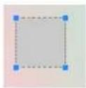
A field that is not being used in any tasks is displayed in gray.
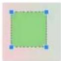
A field that is being used in a task is displayed in green. Used fields can be edited but not deleted.
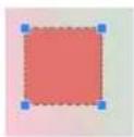
A field for which there is currently an alarm event is displayed in red.
5.3 Tasks
This tab is displayed when you click Configuration... in the VCA tab in Configuration Manager. Before defining tasks, specify the sensitive area and the motion detection parameters:
- Section 5.6.1 Sensitivity Settings, page 57
Movements can only be detected and analyzed within the sensitive area.
Each of these settings can be changed at any time.
Overview
A task describes events that trigger an alarm event when detected in the camera image.
Examples of typical events:
- An overall movement (flow) within an area.
- A movement against the flow.
- The camera is tampered with.
The result of a task is an alarm event. An alarm event can be analyzed in a CCTV system in many ways. In this way, a recording can be started, a door closed or an e-mail sent, for example.
To edit a task, you must first highlight it. To do this, click the task. A highlighted task is outlined in blue.
To create and edit a task, you are guided step-by-step through the necessary settings. You can define up to eight tasks.
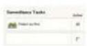
You can see the task list on the right-hand side of the window.
Select a task and then click the name of the task directly in order to change it.
A task can be Active, i.e. an alarm event is generated. A task that is not active does not generate an alarm event.
Click the box next to the name of the task in order to activate it. An active task is indicated by a checkmark.

A task has an orange background if an alarm event is currently being triggered by this task.
A symbol in front of the task name indicates the type of task. The symbol corresponds to the symbol of the wizard that created the task.
New Click here to create a new task. Instead of the task list, the window for selecting a wizard is displayed.
Edit Click here to edit a selected task. The wizard that was displayed for the creation of the task is reopened. You can change individual parameters.
Delete Click here to delete a selected task.
5.4 Creating/Editing a Task
A task is always created or edited using a wizard.
The following wizards are available:
- Section 5.4.2 Tampering, page 53 The camera is tampered with.
- Section 5.4.3 Flow in field, page 54
An overall movement (flow) is detected.
– Section 5.4.4 Counterflow in field, page 55 A movement against the flow is detected.
When you use the wizard to create or edit a task, you have access to the camera image and the popup menu. This means that you can create, edit or delete fields.
In Configuration Manager, the camera image with the popup menu is directly integrated into the IVA 4.0 window. When configuring in the Web browser view, you use the preview on the VCA configuration page.
You can immediately recognize from the color of the arrows whether a flow will trigger an alarm with the given settings:
- Red arrow: alarm event will be generated.
-
Yellow arrow: flow is detected, but an alarm event is not generated because of the filter conditions.
-
Click Next to go to the next step of the wizard.
- Click Previous to go to the previous step of the wizard.
- If you want to skip any further steps, click Finish. The presets are adopted for any unedited steps.
You can change any settings again at any time.
5.4.1 Default Task
When you work with IVA 4.0 Flow for the first time, the default task Detect any flow is already available. This task detects every flow in the entire camera image.
This first preset task corresponds in the configuration to the task type Flow in field (see: Section 5.4.3 Flow in field, page 54).
5.4.2 Tampering

This task generates an alarm event if it must be assumed that the video source (camera) has been tampered with.
Here, you can only activate the filter for the relevant events. You cannot alter the settings for tamper detection. Only the settings from the standard configuration page apply.
An alarm event is generated if one of the activated events occurs (logical connective = OR).
- Scene too bright
Activate this function if tampering associated with exposure to extreme light (for instance, shining a flashlight directly on the lens) should trigger an alarm. The average brightness of the scene provides a basis for recognition.
- Scene too dark
Activate this function if tampering associated with covering the lens (for instance, by spraying paint on it) should trigger an alarm. The average brightness of the scene provides a basis for recognition.
- Signal loss
Activate this function if the interruption of the video signal should trigger an alarm.
- Reference check
Activate this function if a deviation from the reference image on the standard configuration page should trigger an alarm.
5.4.3 Flow in field

This task generates an alarm event if a flow (overall movement) is detected within a certain area. The area is defined by a field in the camera image.
First Step - Define the Field
- Select one of the fields.
To do this, use the list field or click a field in the camera image.
You can also create a new field, edit an existing one or select Whole screen.
2. Debounce time [s]
If a value other than 0 (zero) is selected, the alarm event will not be generated until the flow is detected within the field for at least the specified period.
Final Step - Define the Flow
Here you can precisely limit the properties of a flow that triggers an alarm event. Flows that do not correspond to the properties specified here do not trigger an alarm event.
Direction 1 [°] / Direction 2 [°]
Only flows moving in a certain direction generate an alarm event. The direction is determined by entering an angle.
![BOSCH IVA 4.0 - Direction 1 [°] / Direction 2 [°] - 1](/content/2026/05/1052412/images/b6269a9ff9f91a255bd213f091501366e6978341f08591f17f21c35b3f2b2be6.jpg)
natural_image
Simple geometric diagram with a black circle and a yellow sector, no text or symbols present.0^ corresponds to the direction of movement from right to left.
It is counted counter-clockwise.
Another direction can be optionally entered. In this way, movements are captured in two directions.
You can change the values by
- entering the figures in the fields
- moving the yellow circle segment while holding down the mouse button in order to redefine the direction of movement or
- placing the mouse cursor over one of the edges of the circle segment and moving it while holding down the mouse button in order to change the direction tolerance.
Activity [%]
In this context, an activity is the percentage of the monitored area in which a flow is detected.
An activity that is to trigger an alarm event can be restricted. Change the values if you do not want a particularly low or high activity to trigger an alarm.
- Activate this option if you wish to filter flows based on their activity.
- Enter a minimum and a maximum value for the activity.
The selected values are displayed on the camera image during input by a respectively high number of yellow dots. The number of arrows indicating the detected flow is directly proportional to the activity in the area.
Speed
The speed of the flow that is to trigger an alarm event can be restricted. As the camera is not calibrated to detect flows, no definitive indication of the speed can be provided. Flow speeds are indicated in relation to the background and/or other movements.
Change the values if you do not want a particularly low or high speed to trigger an alarm.
- Activate this option if you wish to filter flows based on their speed.
- For the lowest speed Min., choose between Slow, Medium and Fast.
- For the highest speed Max., again choose between Slow, Medium and Fast. The selected speeds are indicated by two moving dots on the camera image.
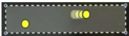
natural_image
Simple diagram with two yellow circles and three gray circular elements on a gray background, enclosed by a dashed border (no text or symbols)- Move or rotate this field with the mouse and place it over an area with a flow. This will enable you to align the flow speed with the selected settings.
5.4.4 Counterflow in field

This task generates an alarm event if a flow moving against a detected overall movement (main flow) is detected within a certain area. This means that an overall, potentially changing, movement is detected, and only flows that go against this direction of movement trigger the alarm.
First Step - Define the Field
- Select one of the fields.
To do this, use the list field or click a field in the camera image.
You can also create a new field, edit an existing one or select Whole screen.
2. Debounce time [s]
If a value other than 0 (zero) is selected, the alarm event will not be generated until the flow is detected within the field for at least the specified period.
Final Step - Define the Counterflow
Here you can precisely limit the properties of a counterflow that triggers an alarm event.
Angle of tolerance for counterflow [°]:
The general direction of movement is automatically recognized as the main flow. Only flows moving in the opposite direction will trigger an alarm event. The maximum deviation of the movement against the main flow is determined by entering an angle. Angles between 0^ and 180^ are valid.
By selecting 0^ , the direction of movement is restricted in such a way that any counter movement will not be detected, while selecting 180^ will ensure that every movement is detected.
Adaption time window [s]:
Specify the period during which there must be activity for a main flow to be detected. In this context, an activity is the percentage of the monitored area in which a flow is detected. As soon as a main flow is detected as such, the counterflow will also be detected.
Activity [%]
The activity of the counterflow that is to trigger an alarm event can be restricted. Change the values if you do not want a particularly low or high activity to trigger an alarm.
- Activate this option if you wish to filter flows based on their activity.
- Enter a minimum and maximum value for the counterflow activity.
The selected values are displayed on the camera image during input by a respectively high number of yellow dots. The number of arrows indicating the detected counter flow is directly proportional to the activity in the area.
Speed
The speed of the counterflow that is to trigger an alarm event can be restricted. As the camera is not calibrated to detect flows, no definitive indication of the speed can be provided. Flow speeds are indicated in relation to the background and/or other movements.
Change the values if you do not want a particularly low or high-speed counterflow to trigger an alarm.
- Activate this option if you wish to filter flows based on their speed.
- For the lowest speed Min., choose between Slow, Medium and Fast.
- For the highest speed Max., again choose between Slow, Medium and Fast. The selected speeds are indicated by two moving dots on the camera image.
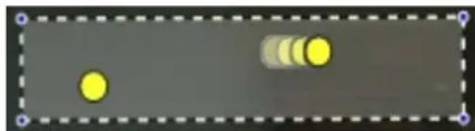
natural_image
Simple diagram with two yellow circles and three gray circles on a gray background, enclosed in a dashed border (no text or symbols)- Move or rotate this field with the mouse and place it over an area with a flow. This will enable you to align the flow speed with the selected settings.
5.5 Statistics
When you select the Statistics tab, histograms with statistics on the relevant detected movements are displayed on the right-hand side of the window, either for a selected field or for the whole screen. You can either select the field in the camera image by clicking it or click one of the tabs on the right-hand side of the window. A tab is shown here for the whole screen and for each respective field.
The statistics help you to refine the filter criteria for flows.
The creation of the displayed statistics starts as soon as you open the IVA 4.0 Flow window.
The longer the window is left open, the more values will be entered into the statistics.
The statistics show four histograms:
- One for slow, medium and fast movements: accumulation of objects moving at a specified speed in a certain direction.
- Activity Histogram [% of area] : accumulation of activity
The lines indicate the percentage of flows for which the respective value was detected. The higher the line, the more flows matched the particular criterion. The histograms distinguish between flows that trigger an alarm (red line) and those that do not (green line).
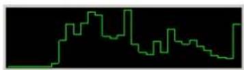
Green: set of flows with no alarm
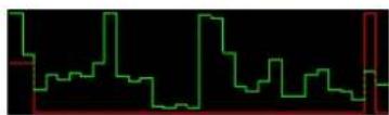
Red: set of flows with alarm
Click Reset to begin building statistics again.
5.6 Configuration
This tab provides access to basic settings that you should specify before defining the individual tasks.
The settings and values defined here are valid for all tasks.
5.6.1 Sensitivity Settings
Sensitive Area
The sensitive area is that part of the image seen by the camera that is analyzed. Objects moving outside the sensitive area cannot generate an alarm event even if they are caught by the camera.
For more details, refer to: Section 4.7.3 Sensitive Area, page 46.
Tracking Parameter
Define the following parameters to further define movement detection:
- Tracking sensitivity
Set a value with the slide control.
Max.: Even minor activities are detected as a flow. This setting is useful if the camera has a small tilt angle and in environments in which objects are often hidden.
However, this setting may mean that camera noises (especially in low-visibility conditions) are also detected as movements.
Min.: This setting is useful in simple environments in which objects move in a straight line and are not hidden during their movement through the area concerned.
- Min. tracking duration [s]
Enter a value between 1 and 4 seconds.
A movement must span this period for it to be detected as a flow.
Activate this option if slow movements are also to be detected.
- Min. tracking distance
The value indicates the distance the objects generating the movement have to cover for a flow to be detected. Small values will trigger an alarm event for slight movements.
Activate this option if quick movements are also meant to be detected as a flow.
At least one of the last two options must be activated at all times for a flow to be detected. High encoding power may require a longer tracking duration.
For more details, refer to: Section Flow Detection Notes and Limitations, page 49.
6 IVA and VG4 AutoDome
If you implement IVA 4.0 or IVA 4.0 Flow with VG4 AutoDome, please note the following:
– There are ten different profiles available for configuring IVA 4.0 (see also:
Section 3.1 Configuration with Configuration Manager, page 11).
Each profile can be assigned to a different preset. Each preset can have its own IVA configuration.
Define the camera positions for the individual presets before starting to configure IVA 4.0.
- Once you have assigned an IVA 4.0 profile to a preset, AutoDome is blocked to other users for approximately ten minutes.
- An IVA 4.0 image data analysis is launched approximately two seconds after AutoDome has recalled a preset. It is irrelevant whether this is part of a tour or whether it is completed manually.
When presets are recalled as part of a tour, the minimum dwell period for a preset should not be below ten seconds; it should be at least one minute.
- As soon as AutoDome is moved to a new position or the zoom, iris or focus settings are changed, IVA 4.0 is no longer active for this scene.
This also applies in the event that Autotracker is used following an alarm input.
- As soon as a message from VG4 AutoDome is displayed on the camera image, IVA 4.0 is no longer active for this preset. Recall this preset to reactivate IVA 4.0 for this scene.
- Use the Inactivity function to ensure that the camera automatically recalls a preset when it becomes inactive. This is particularly important with AutoDomes where the images are not viewed immediately. For more information, refer to the AutoDome documentation.
- Some of the AutoDomes will enable you to reuse an alarm event triggered by IVA 4.0 as an alarm input. Thus, for example, an event detected on preset 1 can cause the recall of another preset.
7 Display of Units of Measurement
In the English-language user interface in the Configuration Manager program, you can display units of measurement according to the Anglo-American measurement system.
- Close the Configuration Manager program.
- Click Start > My Computer.
- Right-click in the window and select Properties from the popup menu.
The System Properties window opens.
- Click the Advanced tab.
- Click Environment Variables.
The relevant window opens.
- Click in the User variables area on New.
The relevant dialog box opens.
- Enter:
Variable name: LANG
Variable value: us
- Close all windows by clicking OK.
- Start Configuration Manager.
The units of measurement are now displayed according to the Anglo-American unit system. The user interface is in the English language.
Delete this user variable in order to return to the original display.
This user variable is only valid for the relevant Windows login. You can set up various user accounts under Windows so the display varies depending on the Windows login.
Index
A
Activation key 7, 8
Activity 55, 56
Alarm state 12, 13
Anchor point
calibration 43
Arrows (Flow) 49
AutoDome 58
calibration 39, 42
VCA configuration 11, 12
B
Backup 22
C
Calibration 39
Calibration plane 42
Camera image 18, 50
popup menu 19, 51
Clear 29
Color
object property 28
the basics 15
Configuration Manager 11
Counterflow 55
speed 56
Cube
calibration 43
Cube size 43
F
Field
creating 19, 51
editing 20, 51
explanation 14
Filter
aspect ratio 26
object direction 27, 54
object movement 27
object size 26
speed 27
FIR camera 45
Flow 54
H
Head detection 30, 45
Height of camera position 39, 44
|
Image stabilization 45
Installation code 7
IVA
in recordings 7
L
License 7
Line
creating 19
direction 30
editing 21
explanation 14
M
Meta data 12
Movement
along a path 33
in an area 24
over a line 30
N
Node
deleting 20
inserting 20
0
Object
changed 32
explanation 14
idle 35, 45
loitering 31
marked 17
marking 18
removed 35, 45
Object outlines 16
Online Help
IVA 4.0 17
IVA 4.0 Flow 49
Outline
green line 16
orange 16
red 16
P
Precision 25, 38
Profile
AutoDome 58
R
Reflected light 9
Roll angle 39, 44
Route
creating 19
direction 33
editing 21
explanation 15
Rule editor 22
S
Sensitive area 46, 57
explanation 14
Settings, global 44
Size Constraint 44
Statistics 38, 56
Symbols 5
T
Tamper detection
task 34, 53
Task
alarm 23, 52
creating 23, 53
default 24, 53
deleting 23, 53
editing 23, 53
entering objects 36
explanation 15
leaving area 36
name 23, 52
similarity search 37
Task Editor 22
Tasks 22, 52
Tilt angle 39, 43
U
Units of measurement 59
Using a property 25
V
VCA (tab) 11
Video errors 34, 53
W
Wizard
explanation 15
Y
Yellow flag 17
Bosch Security Systems
© Bosch Security Systems, 2009
- IVA 4.0
- BOSCH
- Table of Contents
- Introduction 5
- Introduction
- Welcome to the IVA Intelligent Video Analysis Help
- About this Manual
- Conventions in this Manual
- CAUTION!
- NOTICE!
- Intelligent Video Analysis
- New IVA 4.0 Functions
- Requirements
- Setup
- IVA 4.0-Compatible Senders and Cameras
- Forensic Search in Recordings
- License
- Select SETTINGS > Advanced Mode > Service > Licenses.
- Requesting Activation Keys
- Open the following Website from any PC:
- If you already have an account, log in.
- Enter the authorization number that you received when you purchased IVA 4.0.
- Then click the check mark next to the input window.
- The next step is to enter the installation code along with brief information about the installation location. You may also add a comment.
- Click Submit.
- Entering Activation Keys
- Open the Web browser view of the device again.
- Upgrade from IVA 3.5
- Limitations
- Note:
- Configuration
- Configuration with Configuration Manager
- Select IVA 4.0 or IVA 4.0 Flow as the Analysis type.
- Click Configuration....
- Alarm status
- Configuration Using Web Browser
- Click Configuration....
- 4
- |
- V
- A
- •
- The Basics
- Objects
- Sensitive Area
- Calibration
- Field
- Line
- Route
- Color
- Task
- Wizard
- Filter Hierarchy
- Object Outlines and Other Image Information
- Description
- IVA 4.0 User Interface
- T a s k s
- Statistics
- Object Properties
- Camera image
- Popup Menu in the Camera Image
- - Cut
- - Copy
- - Paste
- - Create Field
- - Create Line
- - Create Route
- - Show
- - Sensitive Area
- - Object Outlines
- - Object Bounding Boxes
- - Items
- - Trajectories
- - Head Detection Flag
- - Insert Node
- - Delete Node
- - Advanced > IVA Task Editor
- Editing a Field
- Editing a Line
- Editing a Route
- The IVA Task Editor
- Creating a Backup with the IVA Task Editor
- Recreating the Saved Configuration
- Tasks
- Overview
- New
- Edit
- Creating/Editing a Task
- Default Task
- Object in field
- First Step - Define the Field
- Debounce time [s]
- Next Step - Approximation
- Next Step - Define the Conditions
- Visualization of the property
- Marked object
- Property activated
- Object size [m2]
- Aspect ratio v/h
- Speed [km/h]
- Direction 1 [°] / Direction 2 [°]
- Next Step - Define the Color
- Value
- Colors
- P r e c i s i o n
- Clear color
- Final Step - Define the Head Detection Conditions
- Prerequisite
- Use head detection filter
- Crossing line
- First Step - Define the Lines
- Debounce time [s]
- Direction
- Next Step - Define the Trigger
- Loitering
- - Radius [m]
- - Time [s]
- Condition change
- First Step - Define the Initial Conditions
- Next Step - Define the Time Span
- Next Step - Define the Field
- Following route
- First Step - Define the Route
- - Min. match [%]
- - Max. gap [%]
- - Direction
- Tampering
- - Global change
- - Scene too bright
- - Scene too dark
- - Scene too noisy
- - Signal loss
- - Reference check
- Removed object
- Final Step - Define the Color
- Idle object
- Entering field
- Next Step · Approximation
- Next Step · Define the Color
- Leaving field
- Similarity search
- Approximation
- Statistics
- Configuration
- Calibration
- Calibrating with Calibration Elements
- Elevation [m]
- Horizon
- Popup Menu
- Verify
- Applying the Calibration
- Calibrating with Calibration Plane
- Adjusting the Calibration Plane
- Editing Calibration Settings
- Global Settings
- Size Constraint
- Head Detection
- Notes on Finding Heads
- Functions
- - Enhanced separation
- Reset
- Apply
- Sensitive Area
- Rubber Band
- Small Square
- Medium Square
- Large Square
- Clear All
- Object Properties
- IVA 4.0 Flow
- The Basics and Image Information
- Flow Detection Notes and Limitations
- IVA 4.0 Flow User Interface
- - Sensitivity Settings
- Camera image
- OK
- C a n c e l
- Popup Menu in the Camera Image
- - Advanced >IVA Task Editor
- Tasks
- Creating/Editing a Task
- Default Task
- Tampering
- Flow in field
- Final Step - Define the Flow
- Activity [%]
- Speed
- Counterflow in field
- Final Step - Define the Counterflow
- Angle of tolerance for counterflow [°]:
- Adaption time window [s]:
- Statistics
- Configuration
- Sensitivity Settings
- Tracking Parameter
- - Tracking sensitivity
- - Min. tracking duration [s]
- - Min. tracking distance
- IVA and VG4 AutoDome
- Display of Units of Measurement
- Index
- B
- C
- F
- H
- L
- M
- N
- 0
- P
- R
- S
- T
- U
- W
- Y
Brand : BOSCH
Model : IVA 4.0
Category : Unknown