
ARD-FPBEW2-H2 - Fingerprint Reader BOSCH - Free user manual and instructions
Find the device manual for free ARD-FPBEW2-H2 BOSCH in PDF.


| Product Type | Fingerprint Reader |
| Brand | Bosch |
| Model | ARD-FPBEW2-H2 |
| Category | Access Control |
| Dimensions (H x W x D) | 50 mm x 50 mm x 20 mm |
| Weight | Approx. 100 g |
| Power Supply | 12 V DC / 100 mA |
| Fingerprint Capacity | Up to 1,000 templates |
| Sensor Type | Optical / Capacitive |
| Interface | Wiegand (26/34 bit), RS-485 |
| Operating Temperature | -20°C to +60°C |
| Ingress Protection | IP65 |
| Security Features | Encrypted data transmission, anti-tamper switch |
| LED Indicators | Red/Green status LED |
| Mounting | Wall mount (surface or flush) |
| Material | Polycarbonate / ABS |
| Compatibility | Bosch access control panels and third-party systems |
| Certification | CE, FCC |
| Maintenance | Clean sensor with soft dry cloth; avoid solvents |
| Spare Parts Available | Mounting bracket, cable, screw kit |
| Package Contents | Fingerprint reader, mounting hardware, quick start guide |
Frequently Asked Questions - ARD-FPBEW2-H2 BOSCH
User questions about ARD-FPBEW2-H2 BOSCH
0 question about this device. Answer the ones you know or ask your own.
Ask a new question about this device
Download the instructions for your Fingerprint Reader in PDF format for free! Find your manual ARD-FPBEW2-H2 - BOSCH and take your electronic device back in hand. On this page are published all the documents necessary for the use of your device. ARD-FPBEW2-H2 by BOSCH.
USER MANUAL ARD-FPBEW2-H2 BOSCH
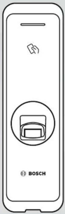
ARD-FPBEW2-H2 Fingerprint Reader, Multiclass
ARD-FPBEW2-H2
natural_image
Front view of a smartphone with a Bosch logo and a circular icon containing a device (no text or symbols on the device itself)en
Installation manual
Table of contents
| 1 | Safety and handling 4 | |
| 2 | Introduction 5 | |
| 2.1 Components 5 | ||
| 2.2 Names and function of parts 6 | ||
| 2.3 Cables and Connectors 7 | ||
| 2.4 How to enroll a fingerprint 9 | ||
| 3 | Installation 11 | |
| 3.1 Fixing the bracket and the product 11 | ||
| 3.2 Power supply connection 13 | ||
| 3.3 Network connection - TCP/IP 14 | ||
| 3.4 Wiegand connection 15 | ||
| 3.5 RS 485 Connection 16 | ||
| 3.6 Resetting Network Settings 16 | ||
| 3.7 Restoring the Factory Defaults | 16 | |
| 4 | Technical Data | 17 |
| 4.1 Product Specifications | 17 | |
| 4.2 Dimensions | 19 | |
| 5 | UL | 20 |
| 5.1 UL 294 requirements | 20 | |
| 6 | FCC | 21 |
| 6.1 Compliance information | 21 | |
1 Safety and handling
Failure to follow these safety instructions could result in fire, electric shock, injury, or damage to the product or other property. Read all the safety information before installing or using the product.
Download, read and follow the respective technical documentation at boschsecurity.com (where available) or read the documentation provided in the packaging. Retain documentation for future reference.
Installation
- Do not install the product in a place with direct sunlight, moisture, dust, or soot.
- Do not install the product in a place with heat from an electric heater.
- Do not install the power supply cable in a passage area.
- Do not install the product near highly magnetic objects.
- Do not install the product in a place with electromagnetic interference.
- Install the product in a dry place.
- When installing more than one device, allow space between the devices.

Notice!
In case of malfunction, contact Bosch After-Sales Service.
Do not attempt to repair the product yourself or free after-sales service will not be provided.
Battery disposal and replacement
- Replace the RTC battery with the correct type of battery.
- Discard the battery according to the appropriate regional or international waste regulations.
Handling the product
- Do not drop the product.
- Do not apply any impact to the product.
- Do not contaminate or damage the fingerprint contact unit with foreign substances.
- Do not spill any liquids on the product.
- Only operate the product from the type of power source indicated on the label. If unsure of the type of power supply to use, contact your dealer.
Cleaning the product
- Wipe the product with a soft and dry cloth.
- Do not apply water, benzene or alcohol.

Notice!
For more information about this product, read the documentation provided in the packaging, or visit us at http://www.boschsecurity.com.
2 Introduction
2.1 Components
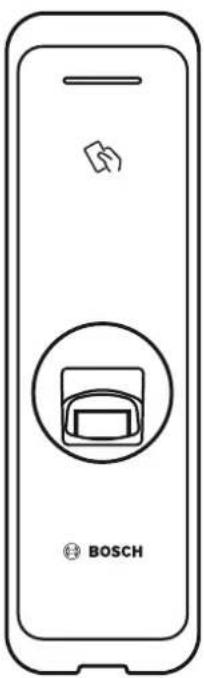 ARD-FPBEW2 ARD-FPBEW2 | 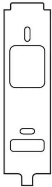 Bracket Bracket |  Ferrite Core(1 EA) Ferrite Core(1 EA) | 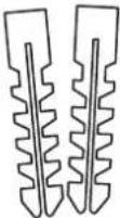 PVC anchor(2 EA) PVC anchor(2 EA) |
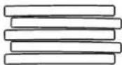 Heat shrink Heat shrink | 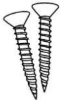 Fixing screw(2 EA) Fixing screw(2 EA) | ||
| Bracket Fixing Screw(Star Shaped) | |||
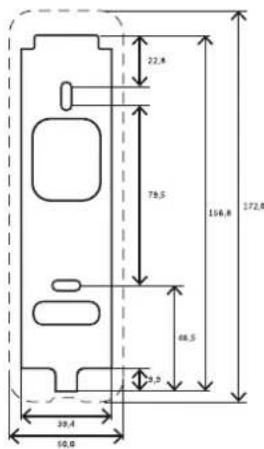 Drilling template Drilling template |  OSS Manual OSS Manual |  SafetyInstructions SafetyInstructions |  QuickInstallationGuide QuickInstallationGuide |
2.2 Names and function of parts
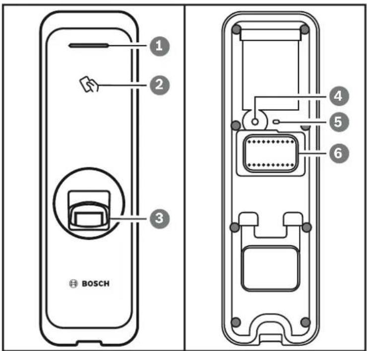
| Item Feature | |
| 1 LED lampIndicates the operational status of the product with the color of the LED lamp. | |
| 2 RF card authentication unitReads RF cards for entering and exiting. | |
| 3 Fingerprint authentication unitReads fingerprints placed on it for entering and exiting. | |
| 4 Reset buttonFor details, see chapters 3.6 and 3.7 | |
| 5 LED lamp for NetworkShows the status of the network connection. | |
| 6 Cable– Wiegand cable– Power cable– RS485 cable– Ethernet connector |
2.3 Cables and Connectors
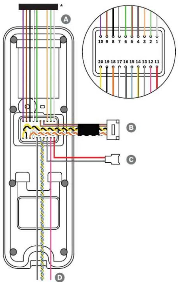
* Cut the required wires off the connector plug.
| Cable Cable name | |
| A Wiegand cable | |
| B Ethernet cable | |
| C Power cable | |
| D RS485 cable | |
| Cable Cable name Color | |
| 1 WG Tamper NO Gray (White stripe) | |
| 2 WG Tamper COM Green (White stripe) | |
| 3 WG Tamper NC Orange (White stripe) | |
| 4 Not used Blue | |
| Brown | |
| 5 Not used Red | |
| Green | |
| 6 WG D0 Green | |
| 7 WG D1 White | |
| 8 WG GND Black | |
| 9 TTL IN1 (LED red) Brown | |
| 10 TTL IN0 (LED green) Purple | |
| 11 PWR +VDC Red | |
| 12 Not used Pink | |
| 13 PWR GND Black (White stripe) | |
| 14 485 TRXN (RxTx-) Yellow (Black stripe) | |
| 15 485 TRXP (RxTx+) Blue (White stripe) | |
| 16 485 PAG White (Black stripe) | |
| 17 ENET TXP White | |
| 18 ENET TXN Orange | |
| 19 ENET RXP Black | |
| 20 ENET RXN Yellow |
2.4 How to enroll a fingerprint
In order to improve the fingerprint authentication rate, register the fingerprint correctly. The reader can recognize a fingerprint even if the angle and position of a user's fingerprint input change. If you register the fingerprint with attention to the following instructions, the authentication rate can be improved.
Selecting a finger for fingerprint input

- In preparation for the case that the fingerprint of a specific finger cannot be used, for example if the user is lifting a load with one hand or a finger gets hurt, up to 10 fingerprints for each user can be registered.
- In the case of a user whose fingerprint cannot be recognized well, the authentication rate can be improved by enrolling the same finger twice repeatedly.
- If a finger has a cut or the fingerprint is blurry, select another finger for the fingerprint.
- It is recommended to use the index finger or the middle finger when scanning the fingerprint. The authentication rate can be reduced if it is difficult to place another finger at the center of fingerprint sensor accurately.
Fingerprint enrollment method
- Place the finger with the fingerprint to be registered on the fingerprint authentication unit and press the finger gently for better authentication.
- Wait for the instructions of the management system to place the finger a second time on the sensor. Scan the fingerprint of the registered finger again.


Cautions for enrolling a fingerprint
When a fingerprint is recognized, it is compared with the initially registered fingerprint, so the initial fingerprint enroll is the most important. Pay attention to the following matters when enrolling the fingerprint:
- Place the finger deep enough to contact with the sensor completely.
- Place the center of the fingerprint in the center of the sensor.
- If a finger has a cut or the fingerprint is blurry, select another finger for the fingerprint.
- Scan the fingerprint correctly without moving according to the instruction on the screen.
- If you make the finger upright so that the contact area with the sensor has decreased or the angle of finger has warped, fingerprint authentication may not be performed.




Failure during fingerprint recognition
The reader can recognize a fingerprint regardless of a change of season or finger condition. However, the authentication rate may vary according to the external environment or fingerprint input method.
If the fingerprint authentication cannot be done smoothly, it is recommended to take the following measures:
- If the finger is smeared with water or sweat, dry off the finger and then scan the finger.
- If the finger is too dry, blow your breath on the fingertips and then scan the finger.
- If the finger has a cut, register the fingerprint of another finger.
- The initially registered fingerprint often may have not been scanned correctly, so register the fingerprint again according to ‘Cautions for enrolling a fingerprint’.
3 Installation
3.1 Fixing the bracket and the product
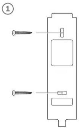
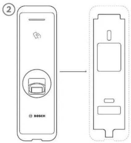
- Determine the correct position to install the bracket using the provided drilling template.
- Fix the bracket firmly using fixing screws through the bracket to the position where the device will be installed.
- Install the device onto the fixed bracket.
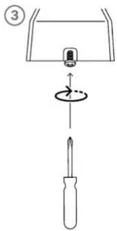
- Assemble the device to the bracket by rotating the star-shaped fixing screw.
- When assembling the product with the bracket, use the included bracket fixing screw (star-shaped) instead of the product fixing screw for enhanced security.
Installing the device on a concrete wall
- Drill holes on the wall.
- Insert the PVC anchors.
- Fix the anchors with fixing screws.
- Maintain a minimum separation distance to avoid RF interference (see table below).
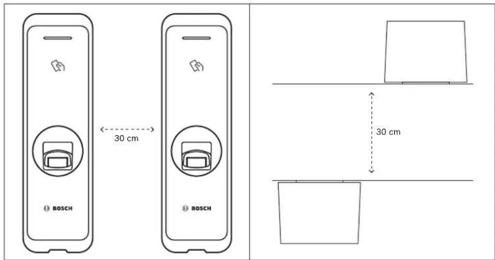
| Wall thickness Distance | |
| 100 mm 270 mm | |
| 120 mm 250 mm | |
| 150 mm 170 mm |
3.2 Power supply connection
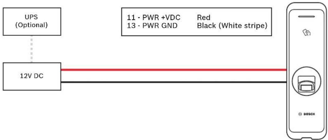
flowchart
graph LR
    A["UPS (Optional)"] --> B["12V DC"]
    C["11 - PWR +VDC Red 13 - PWR GND Black (White stripe)"] --> D["BOSCH"]
    B --> D
- Use a power supply adaptor of DC 12 V (± 10%) with a minimum of 1,500 mA which has obtained the approval of IEC/EN 60950-1. If you wish to connect and use another device to the power supply adaptor, you should use an adaptor with a current capacity which is the same or larger than the total power consumption required for the terminal and another device.

Warning!
Do not connect the device to the DC power supply(or adapter) and PoE power supply at the same time.

Notice!
Make sure to isolate the power connector cables if PoE is used for power supply.
3.3 Network connection - TCP/IP
LAN connection (connecting to a hub)
You can connect the product to a hub using a general type CAT-5 cable (or higher).
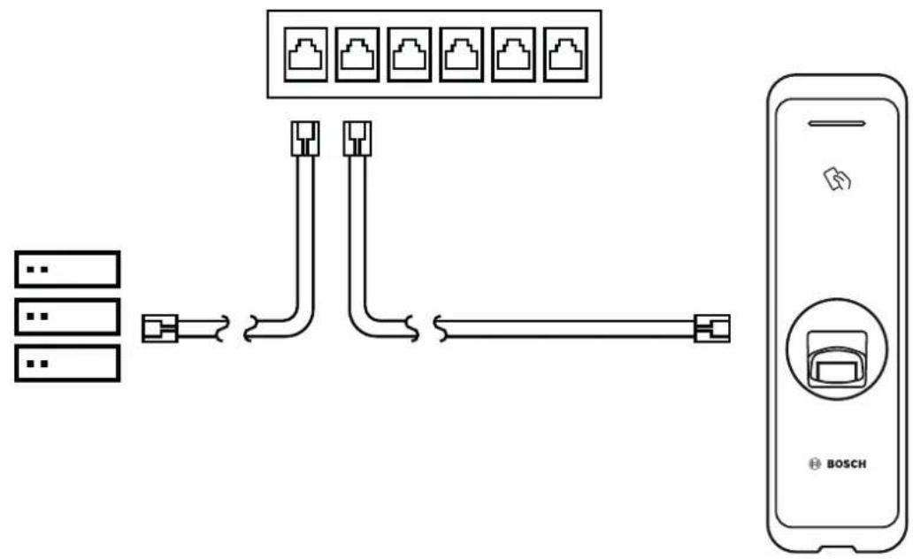
flowchart
graph LR
    A["Server"] --> B["Switch"]
    B --> C["Data Link"]
    C --> D["Data Port 1"]
    C --> E["Data Port 2"]
    C --> F["Data Port 3"]
    C --> G["Data Port 4"]
    C --> H["Data Port 5"]
    C --> I["Data Port 6"]
    C --> J["Data Port 7"]
    C --> K["Data Port 8"]
    C --> L["Data Port 9"]
    C --> M["Data Port 10"]
    C --> N["BOSCH"]
LAN connection (connecting to a PC directly)
The ARD-FPBEW2 has an automatic MDI/MDIX function so that it can be connected to a PC directly using a normal straight type CAT-5 cable (or higher), not a cross cable.
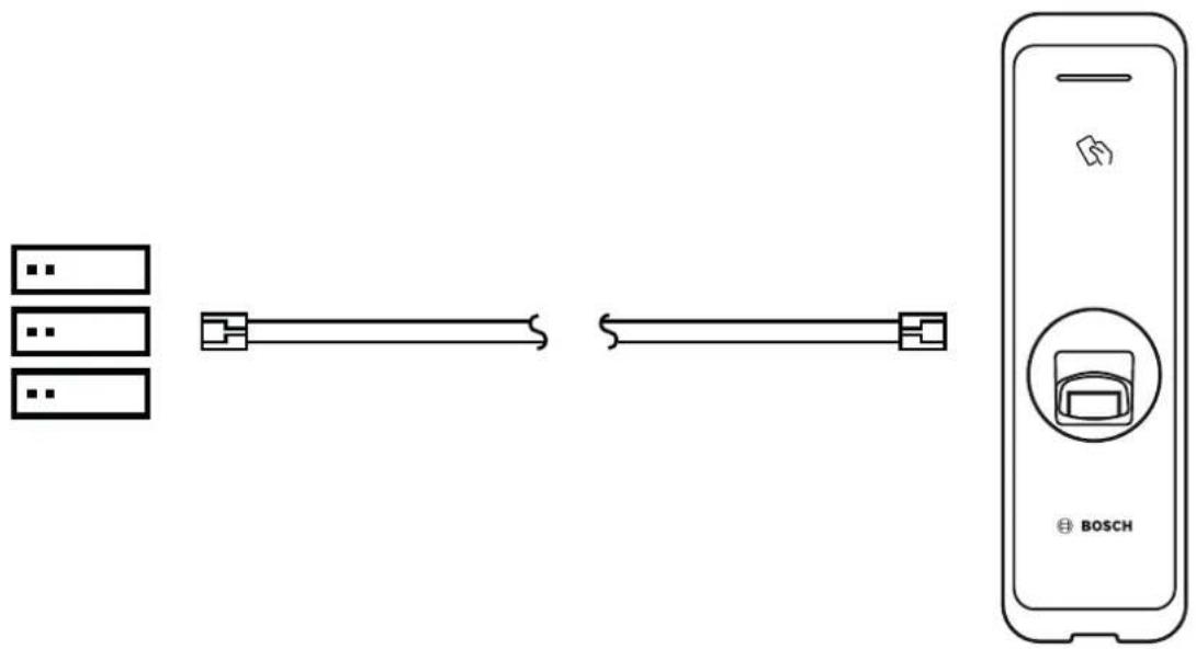
flowchart
graph LR
    A["Server Rack"] --> B["Connector"]
    B --> C["Switch"]
    C --> D["Chipset Display"]
    D --> E["BOSCH"]
3.4 Wiegand connection
1 - WG Tamper NO Gray (White stripe)
2 - WG Tamper COM Green (White stripe)
3 - WG Tamper NC Orange (White stripe)
6 - WG D0 Green
7 - WG D1 White
8 - WG GND Black
9 - TTL IN 1 (LED red) Brown
10 - TTL IN 0 (LED green) Purple
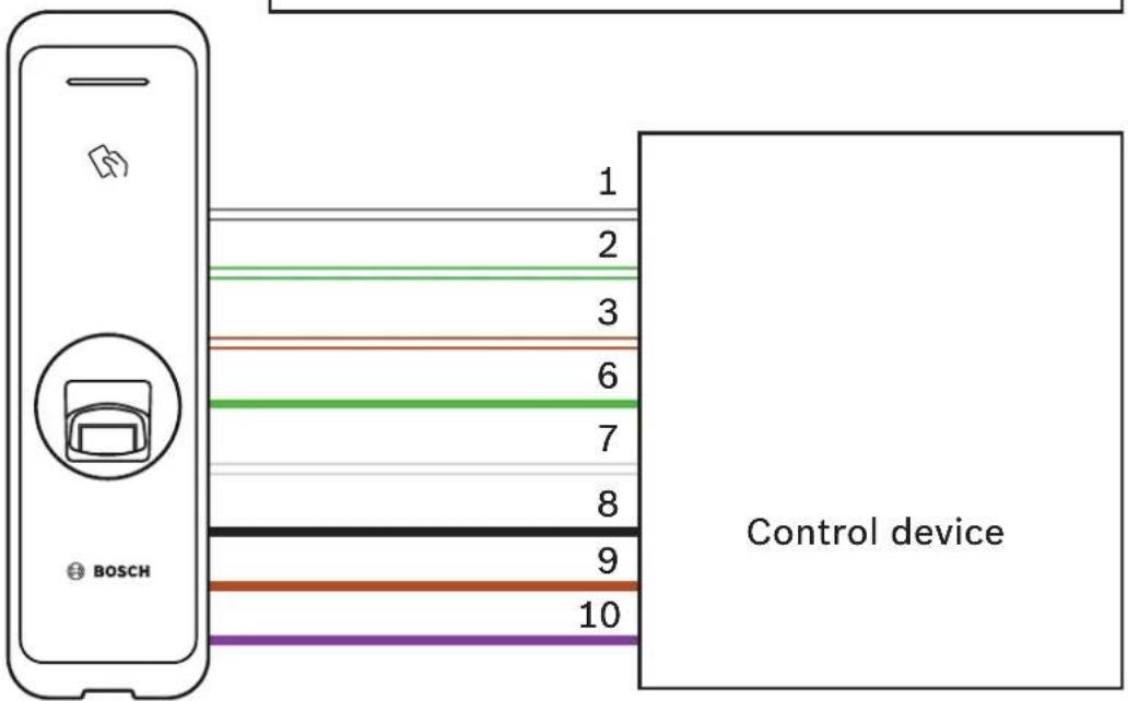
3.5 RS 485 Connection
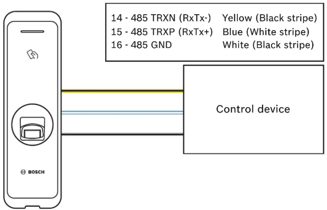
3.6 Resetting Network Settings
- Turn the power on.
- Press the network reset button on the rear of device until the device restart automatically.
- Connect the device with default values.
- TCP/IP address: DHCP address assignment (If DHCP address assignment is fails, 169.254.x.x will be set.)
- Server mode: Disabled
- RS-485: PC connection, 115200 bps
- Change the TCP/IP address or RS-485 information.
- Turn the power off later on and then check the network setting is properly.
3.7 Restoring the Factory Defaults
This will delete all data and root certificate on the device and reset the settings.
- Turn the power on.
- Press the reset button three times quickly.
- When the yellow LED is blinking, press the reset button again.
NOTE
- If there is no root certificate on the device, you cannot restore the factory defaults.
4 Technical Data
4.1 Product Specifications
General
| Biometric Fingerprint | |
| Storage templates - Template on device | - Template in secure database of AMS or BIS/ACE |
| Modes for access - Fingerprint plus card | - Fingerprint or card- Card only- Fingerprint only |
| Max. user - 400.000 (1:1 matching) | - 100.000 (1:N matching) |
| Max. template in DB - 4.000.000 (10 templates per person; 1:1 matching) | |
| Card compatibility - EM (26 bit standard coding scheme)- HID Prox (26 / 37 bit standard coding scheme)- MIFARE classic (ISO 14443A CSN / Bosch code)- MIFARE DESFire EV1 (ISO 14443A CSN / Bosch code)- iCLASS (26 / 37 bit standard coding scheme)- HID Corporate-1000 (35 / 48 bit standard coding scheme)- iCLASS SE (26 / 37 bit SIO - Secure Identity Object)- iCLASS Seos (26 / 37 bit SIO - Secure Identity Object) | |
Electrical
| Operating voltage 12 VDC | |
| Current draw 600 mA max. (peak) | |
| Memory - 2GB flash | - 256MB RAM |
| CPU 1.2 GHz Quad Core | |
| Sound Multi-tone buzzer | |
| Tamper detection Supported | |
| Interfaces - Ethernet (TCP/IP 10/100 Mbps) with PoE (IEEE 802.3af)- RS-485 (OSDP v2)- Wiegand | |
Mechanical
| Housing material Polycarbonate | |
| Dimensions (H × W × D) 50 mm x 172 mm x 38 | 2 mm (top)50 mm x 172 mm x 43.5 mm (bottom) |
| Weight 251 g | |
| Color Silver / Black | |
| LED color | Multicolor |
Environmental
| Impact protection | IK 09 |
| Environmental rating | IP 67 |
| Operating temperature | -20°C to +50°C (-4°F to 122°F) |
| Humidity | 0% to 80%, no condensation of water |
4.2 Dimensions
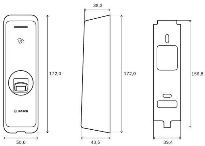
5 UL
5.1 UL 294 requirements
The following UL 294 levels apply:
- Destructive attack - level 2
- Line security - level 2
- Endurance - level 1
- Standby power-level 1
If the unit is powered by an external power supply, you can use:
- UL Listed Class 2 power supply with 12VDC
- UL 294B Listed PoE power source
6 FCC
6.1 Compliance information
THIS DEVICE COMPLIES WITH PART 15 OF THE FCC RULES.
Operation is subject to the following two conditions:
- This device may not cause harmful interference, and
- This device must accept any interference received, including interference that may cause undesired operation.
Note: This equipment has been tested and found to comply with the limits for a Class B digital device, pursuant to part 15 of the FCC Rules. These limits are designed to provide reasonable protection against harmful interference in a residential installation. This equipment generates, uses, and can radiate radio frequency energy and, if not installed and used in accordance with the instructions, may cause harmful interference to radio communications. However, there is no guarantee that interference will not occur in a particular installation. If this equipment does cause harmful interference to radio or television reception, which can be determined by turning the equipment off and on, the user is encouraged to try to correct the interference by one or more of the following measures:
- Reorient or relocate the receiving antenna.
- Increase the separation between the equipment and receiver.
- Connect the equipment into an outlet on a circuit different from that to which the receiver is connected.
- Consult the dealer or an experienced radio/TV technician for help.
Modifications not expressly approved by the manufacturer could void the user's authority to operate the equipment under FCC rules.
This appliance and its antenna must not be co-located or operation in conjunction with any other antenna or transmitter.
A minimum separation distance of 20 cm must be maintained between the antenna and the person for this appliance to satisfy the RF exposure requirements.
Bosch Access Systems GmbH
Charlottenburger Allee 50
52068 Aachen
Germany
www.boschsecurity.com
© Bosch Access Systems GmbH, 2019
- ARD-FPBEW2-H2 Fingerprint Reader, Multiclass
- Safety and handling
- Installation
- Notice!
- Battery disposal and replacement
- Handling the product
- Cleaning the product
- Introduction
- Components
- Names and function of parts
- Cables and Connectors
- How to enroll a fingerprint
- Fingerprint enrollment method
- Cautions for enrolling a fingerprint
- Failure during fingerprint recognition
- Installation
- Fixing the bracket and the product
- Installing the device on a concrete wall
- Power supply connection
- Warning!
- Network connection - TCP/IP
- LAN connection (connecting to a hub)
- LAN connection (connecting to a PC directly)
- Wiegand connection
- RS 485 Connection
- Resetting Network Settings
- Restoring the Factory Defaults
- NOTE
- Technical Data
- Product Specifications
- Dimensions
- UL
- UL 294 requirements
- FCC
- Compliance information
Brand : BOSCH
Model : ARD-FPBEW2-H2
Category : Fingerprint Reader