
35XT - Microphone Azden - Free user manual and instructions
Find the device manual for free 35XT Azden in PDF.


| Product Type | Dynamic Handheld Microphone |
| Dimensions | Approx. 5.0 x 2.0 inches (12.7 x 5.1 cm) |
| Weight | Approx. 10.5 oz (298 g) |
| Power Supply | No battery required (passive dynamic) |
| Frequency Response | 50 Hz – 15 kHz |
| Polar Pattern | Cardioid |
| Connector | XLR-3 male |
| Functions | On/off switch, rugged metal construction |
| Maintenance & Cleaning | Wipe with a damp cloth; avoid moisture; clean grille with mild soap |
| Safety | Do not drop; keep away from extreme temperatures |
| Spare Parts & Repairability | Replaceable grille and cartridge; XLR connector replaceable |
| General Information | Designed for vocal and instrument applications; high SPL handling |
Frequently Asked Questions - 35XT Azden
User questions about 35XT Azden
0 question about this device. Answer the ones you know or ask your own.
Ask a new question about this device
Download the instructions for your Microphone in PDF format for free! Find your manual 35XT - Azden and take your electronic device back in hand. On this page are published all the documents necessary for the use of your device. 35XT by Azden.
USER MANUAL 35XT Azden
Thank you for purchasing the Azden 330 Dual-Channel Wireless Microphone system. The components included with your system will vary depending on the system configuration you purchased. Below are the possible system configurations available with the 330UPR Dual-Channel Receiver.
330LT
1 x 330UPR Dual-Channel Receiver
1 x Stereo Mini-Plug to Dual XLR Cable
1 x Stereo Mini-Plug to Mini-Plug Cable
2 x 35BT Body-Pack Transmitter
2 x EX-503L Lavalier Microphone
330LH
1 x 330UPR Dual-Channel Receiver
1 x Stereo Mini-Plug to Dual XLR Cable
1 x Stereo Mini-Plug to Mini-Plug Cable
1 x 35BT Body-pack Transmitter
1 x EX-503L Lavalier Microphone
1 x 35HT Handheld Microphone / Transmitter
330LX
1 x 330UPR Dual-Channel Receiver
1 x Stereo Mini-Plug to Dual XLR Cable
1 x Stereo Mini-Plug to Mini-Plug Cable
1 x 35BT Body-Pack Transmitter
1 x EX-503L Lavalier Microphone
1 x 35XT XLR Plug-in Transmitter
CAUTION
- Do not use batteries other than the ones specified in this manual. Do not mix fresh battery with used battery.
- When installing batteries, make sure the battery polarity is correct as marked inside the battery compartment.
- Remove the batteries before long-term storage of the transmitters or receiver.
- Do not submerge any of the components in water.
Quick Start Guide
- Install new AA alkaline batteries into the receiver and transmitters.
- Connect the EX-503L lavalier microphone(s) to the MIC input on the 35BT(s).
- Turn on your transmitters. You should see information displayed on the LCD. Be sure to also turn the AUDIO switch to ON.
- Set the transmission frequency for each transmitter by pressing the Channel Up/Down buttons. Each transmitter will need to be set to a different frequency in order to run them at the same time without interference. Keep the group number the same (1st two digits) and separate the frequency numbers (2nd two digits) by at least 16.
- Turn on both channels of the receiver. You can toggle the information for each channel by pressing the DISP 1/2 button located below the LCD.
- Set the group and frequency numbers on each channel of the receiver to match those set previously on the transmitters.
- The receiver should now be connected to the transmitters. To check, you can connect headphones to the PHONE jack of the receiver and listen for audio.
For a more detailed description of component controls, functions and setup, please continue reading this manual.
330UPR Dual-Channel Receiver

1. Antennas
For the best reception, the antennas should be pointed in an upward position.
2. Power Switch for each Channel
There are separate power switches for Channel 1 and 2.
3. Universal LCD Display for Ch. 1 and 2
Multifunctional display shows battery life, signal strength, channel selection and frequency selection. Refer to "LCD Display Readouts" in this manual for further details.
4. CHANNEL UP/DOWN Buttons
To change the Group/Frequency number of each channel, use a small, pointy object to press the UP or DOWN button until the desired number is shown on the LCD Display. Keep the button pressed down to fast forward the channel numbers. Once the desired Group/Frequency numbers are selected on the receiver, set the transmitters to match.
5. DISP 1 / 2 Button
Press to switch the LCD Display between Channels 1 and 2.
6. LCD Display MODE Switching Button
Press to switch the LCD Display to show either the Group and Frequency numbers or the actual frequency in MHz being used on each channel.
7. PHONE Jack
This output allows you to monitor sound and is intended for use with headphones. If a stereo headphone is used, Ch. 1 will be heard on the left and Ch. 2 on the right.
8. MIC OUT Jack
The microphone output is a 3.5 mm TRS mini-jack and should only be connected to microphone inputs. Your 330 kit is supplied with both a mini-to-mini and a mini-to-dual XLR cable.
For mini-jack microphone inputs: Use the supplied mini-to-mini cable. Plug one end of the cable into the 330UPR Receiver and the other end into the microphone input of the video camera. Note: by
design, the audio from each channel is output discretely, so that you will get audio from channel 1 on the left side, and audio from channel two on the right side. This makes separate editing in post production of each speaking person possible.
For 3-pin XLR inputs: Use the supplied mini-to-dual XLR cable. Plug the mini-plug end of the cable into the 330UPR Receiver (use the screw-down sleeve to secure it to the receiver) and plug the XLR ends into the microphone inputs on the video camera. Ch. 1 is on the “Tip” and Ch. 2 on the “Ring”.
9. Battery Compartment
Remove the battery compartment lid by sliding it down. Install two fresh alkaline "AA" batteries. Make sure the battery polarity is correct as marked inside the battery compartment. Alkaline batteries will perform best, but Azden's 1HR-3U rechargeable Ni-MH batteries may also be used.
10. DC 6 Volt Input
An optional AC power adaptor/battery charger for Azden's 1HR-3U rechargeable Ni-MH batteries is available for the 330UPR. Azden's part number for this unit is BC-29. Contact Azden or an Azden dealer for more information.
11. Shoe Mount Assembly
First loosen the thumb wheel by turning it counter-clockwise. Slide the square foot of the shoe mount assembly into your camera's shoe mount slot. Secure into place by tightening the thumbwheel by turning it clockwise until snug. Do not over tighten.
35BT Body-Pack Transmitter

12. Battery Compartment
Remove the battery compartment lid by sliding it down. Install two fresh alkaline "AA" batteries. Make sure the battery polarity is correct as marked inside the battery compartment.
13. MIC input Level Control
Located inside the battery compartment, this control enables you to adjust the input level of the microphone. Using the supplied tool, also found inside the battery compartment, turn the dial clockwise to increase, or counterclockwise to decrease the input level.
14. POWER Switch
Switches the 35BT Transmitter "ON" or "OFF"
15. MIC Input Jack
Plug the supplied EX-503L Lavalier Microphone into the MIC input jack. In addition to the EX-503L, other lapel and/or headset microphones with 3.5mm mini plug may also be used with the 35BT.
16. AUDIO Switch
It is best to set the AUDIO switch to "STBY" (standby) prior to first turning the POWER switch "ON". When you are ready to begin transmitting, turn the AUDIO switch ON. The STBY position acts as a mute function that maintains the RF signal but turns off the audio.
17. LCD Display
Multifunctional display shows battery life, audio level and frequency selection. Refer to “LCD Display Readouts” in this manual for further details.
18. CHANNEL UP/DOWN Buttons
Press the UP and DOWN buttons to change the transmission frequency. Group/Frequency numbers are shown on the LCD. Keep the button pressed down to fast forward through numbers. Once the desired Group/Frequency numbers are selected on the transmitter, set the receiver to match. This functions the same on 35XT and 35HT transmitters if they are included with your kit.
35XT Plug-in Transmitter

19. Battery Compartment
Open the battery compartment lid by pushing down on the tab and lifting it up. Install two fresh alkaline "AA" batteries. Make sure the battery polarity is correct as marked inside the battery compartment.
20. POWER Switch
Turns the 35XT Transmitter "ON" or "OFF".
21. AUDIO Switch
It is best to set the AUDIO switch to "STBY" prior to first turning the POWER switch "ON". When you are ready to begin transmitting, turn the AUDIO switch ON. The STBY position acts as a mute function that maintains the RF signal but turns off the audio.
22. MIC Input LEVEL Control
This enables you to adjust the input level of the connected microphone. Using the supplied tool, turn the dial clockwise to increase, or counterclockwise to decrease the input level.
23. Phantom Power Switch
Flip this switch to "48V" to turn on phantom power. Use only for microphones that require phantom power.
24. LCD Display
Multifunctional display shows battery life, audio level and frequency selection. Refer to “LCD Display Readouts” in this manual for further details.
25. CHANNEL UP/DOWN Buttons
Press the UP and DOWN buttons to change the transmission frequency. Group/Frequency numbers are shown on the LCD.
26. MIC Connector/Locking Ring
This 3-pin female XLR connector is the microphone input. Any low impedance microphone with a corresponding male connector may be plugged here. Once the microphone is plugged into the 35XT, the locking ring should be rotated clockwise until snug. To remove the microphone, first rotate the locking ring counterclockwise and then pull the microphone away while pressing the XLR release.
35HT Handheld Microphone/Transmitter

27. LCD Display
Multifunctional display shows battery life, audio level and frequency selection. Refer to “LCD Display Readouts” in this manual for further details.
28. Battery Compartment Cover
Remove the battery compartment cover by twisting it counterclockwise and sliding it down.
29. Battery Compartment
Install two fresh alkaline "AA" batteries. Make sure the battery polarity is correct as marked inside the battery compartment.
30. MIC LEVEL control
This enables you to adjust the audio level of the microphone. Using the supplied tool, turn the dial clockwise to increase, or counterclockwise to decrease the audio level.
31. Channel UP/DOWN buttons
Press the UP and DOWN buttons to change the transmission frequency. Group/Frequency numbers are shown on the LCD.
32. POWER Switch
Located on the bottom of the unit, this switch turns the 35HT Transmitter/Microphone "ON" or "OFF".
LCD Display Readouts

bar
| Category | Value | | :--- | :--- | | A | 30-002 | | B | 30-002 | | C | 30-002 | | D | 30-002 | | E | 30-002 | | F | 579.38575 |330UPR (RECEIVER)
A. Battery level indicator: 3 bars = high, 1 bar = low
B. Channel view indicator: bar under #1 or #2 indicates which channel you are viewing
C. Reception level indicator: 4 bars = high, 1 bar = low
D. Receiving frequency "TV Channel" aka Group number: range 30 - 33
E. Receiving frequency "Channel" aka Frequency number: range 01 - 47
F. Actual frequency in MHz. Push MODE button to see this displayed.
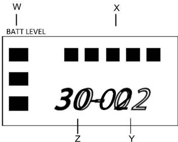
35BT/XT/ HT (TRANSMITTERS)
Z. Transmission frequency "TV Channel" aka Group number: range 30 – 33
Y. Transmission frequency "Channel" aka Frequency number: range 01 - 47
X. Audio input level indicator: 5 bars = high, 1 bar = low
W. Battery level indicator: 3 bars = high, 1 bar = low
Detailed Set Up Instructions
In order to successfully use two transmitters simultaneously with the 330UPR dual-channel receiver, each transmitter must use a different frequency. Furthermore, it is important that these frequencies are set far enough apart so that bleed-through interference does not occur.
When setting frequencies, we recommend the LCD view mode be in "TV Channel Mode" (XX-XX) and not in the "MHz Mode."
The frequency of each unit may be changed by pressing the Up and Down channel buttons located under the LCD in the case of the 35BT, 35XT and 330UPR, or inside the battery compartment in the case of the 35HT.
There are two numbers to consider when setting frequencies in "TV Channel Mode":
• The first two digits are the Group number
• The second two digits are the Frequency number
When selecting frequencies, for best results, both transmitters should be set to the same Group number, but the Frequency numbers should be separated by at least 16 (equal to 2 MHz apart).
Transmitters Setup (35BT, 35XT, 35HT)
- Turn on both transmitters. You should see information displayed on the LCD. Be sure to also turn the AUDIO switch on.
- Select your first transmitter, and change the Group and Frequency numbers in the LCD to the desired setting (ie: 30-01). Use the Channel Up/Down buttons to change the number if necessary.
- Select your second transmitter, and set the second Group and Frequency numbers. Remember: the Group should be the same as your first transmitter, and the Frequency number should be higher or lower by a factor of 16 (ie: 30-17).
330UPR Receiver Setup
- Turn on both CH 1 and CH 2 on the receiver. (Each channel has its own power switch.)
- Make sure the Group and Frequency numbers in the LCD matches that of your first transmitter (ie: 30-01). Use the Channel Up/Down buttons to change the number if necessary.
- Press the DISP 1/2 button to toggle the LCD view over to CH 2.
- Make sure the Group and Frequency numbers in the LCD matches that of your second transmitter (ie: 30-17). Use the Channel Up/Down buttons to change the number if necessary.
- Setup is complete and your receiver should be receiving audio from the transmitters. To check, you can connect headphones to the PHONE jack of the receiver and listen for audio.
Proximity Considerations
Being a wireless system, the 330 series was designed to be used from a distance. For best performance while using two transmitters, it's recommended they are both kept at least 8 feet away from the receiver. This will prevent bleed-through interference between the transmitters. The distance from one transmitter to the other, however, will not affect performance.
Avoiding Interference and Drop Outs
- Interference from other electro-magnetic sources in the environment is always a risk with any wireless radio technology. When using the system in a new location, always listen with headphones and observe the quality of the audio for a few minutes before you start filming. If you notice any interference noise, it will probably be best to change your transmission frequencies. Continue to monitor audio while filming if possible.
- The reliable operating range of the system is approximately 8 – 100 feet. The risk of getting drop outs in the audio signal increases as you extend beyond this range. Keeping line-of-sight between the transmitters and the receiver will help to avoid drop outs, especially at long distances.
- Avoid turning the transmitter antennas horizontal with the ground, a.k.a “planing.” This is potentially an issue to be aware of with the 35XT and 35HT, which are designed to be held in a vertical position, but could inadvertently be turned horizontal. The transmission antennas put out their strongest signal when vertical to the ground. The signal will become weaker if the transmitter is turned to be horizontal, thus increasing the likelihood of drop outs, especially at longer distances.
SPECIFICATIONS
330UPR Receiver
Frequency Range: UHF 188 Selectable Frequencies (566.125-589.875MHz)
Type of Reception: FM
Oscillator: PLL Synthesized
RF Squelch Level: -95 dBm
Frequency Response: 50Hz - 15kHz
S/N Ratio: >57dB (± 5kHz) "A" Weighted
Audio Out: MIC Level – Unbalanced – 3.5mm Mini Jack
-64 dBm - 600 ohms @ ± 5kHz deviation
-28 dBm - 600 ohms @ ± 40kHz deviation
Batteries: 2 "AA" Alkaline (2 x 1.5V), 6-8 hours runtime
2 "AA" Rechargeable Ni-MH (2 x 1.2V)
External Power: 6VDC @ 0.5A
Dimensions: 2 7/8" x 4 7/16" x 1 5/8" (73 x 113 x 40.5mm)
Weight: Approx. 10oz (290g) w/ batteries
35BT Body-Pack Transmitter
Frequency Range: UHF 188 Selectable Frequencies (566.125-589.875MHz)
Oscillator: PLL Synthesized
RF Power: 25mW
Frequency Response: 50Hz – 15kHz
Max Deviation: -11dBm ± 40kHz @ 1kHz Modulation, MIC input
Batteries: 2 "AA" Alkaline (2 x 1.5V), 6-8 hours runtime
2 "AA" Rechargeable Ni-MH (2 x 1.2V)
Dimensions: 2 1/2" x 3 15/16" x 1 1/16" (64 x 100 x 27mm)
Weight: Approx. 6oz (170g) w/ batteries
35XT Plug-in Transmitter
Frequency Range: UHF 188 Selectable Frequencies (566.125-589.875MHz)
Antenna: Internal
Max Input Level: -16dBm
RF Power: 25mW
Input Impedance: 25k ohms
Audio Adjust Range: -65dBm to 46dBm
Batteries: 2 "AA" Alkaline (2 x 1.5V), 6-8 hours runtime
2 "AA" Rechargeable Ni-MH (2 x 1.2V)
Dimensions: 1 9/16" x 1 9/16" x 4 1/2" (40 x 40 x 114mm)
Weight: Approx. 6.4oz (180g) w/ batteries
35HT Handheld Microphone/Transmitter
Frequency Range: UHF 188 Selectable Frequencies (566.125-589.875MHz)
Oscillator: PLL Synthesized
RF Power: 25mW
Frequency Response: 50Hz – 15kHz
Max Deviation: -65dBm (d40kHz)kHz Modulation, MIC input
Batteries: 2 "AA" Alkaline (2 x 1.5V), 6-8 hours runtime
2 "AA" Rechargeable Ni-MH (2 x 1.2V)
Dimensions: 1 7/8'' × 9 9/16''L (48 x 234.5mm)
Weight: Approx. 9.6oz (270g) w/ batteries
Due to constant improvements, specifications are subject to change without notice.
- 330LT
- 330LH
- 330LX
- CAUTION
- Quick Start Guide
- 330UPR Dual-Channel Receiver
- Antennas
- Power Switch for each Channel
- Universal LCD Display for Ch. 1 and 2
- CHANNEL UP/DOWN Buttons
- DISP 1 / 2 Button
- LCD Display MODE Switching Button
- PHONE Jack
- MIC OUT Jack
- Battery Compartment
- DC 6 Volt Input
- Shoe Mount Assembly
- Battery Compartment
- MIC input Level Control
- POWER Switch
- MIC Input Jack
- AUDIO Switch
- LCD Display
- CHANNEL UP/DOWN Buttons
- Battery Compartment
- POWER Switch
- AUDIO Switch
- MIC Input LEVEL Control
- Phantom Power Switch
- LCD Display
- CHANNEL UP/DOWN Buttons
- MIC Connector/Locking Ring
- 35HT Handheld Microphone/Transmitter
- LCD Display
- Battery Compartment Cover
- Battery Compartment
- MIC LEVEL control
- Channel UP/DOWN buttons
- POWER Switch
- LCD Display Readouts
- 330UPR (RECEIVER)
- 35BT/XT/ HT (TRANSMITTERS)
- Detailed Set Up Instructions
- Transmitters Setup (35BT, 35XT, 35HT)
- 330UPR Receiver Setup
- Proximity Considerations
- Avoiding Interference and Drop Outs
- SPECIFICATIONS
- 330UPR Receiver
- 35BT Body-Pack Transmitter
- 35XT Plug-in Transmitter
Brand : Azden
Model : 35XT
Category : Microphone