AT-ANC10S/2 - Network card / adapter Allied Telesis - Free user manual and instructions
Find the device manual for free AT-ANC10S/2 Allied Telesis in PDF.


| Product Type | Network adapter |
| Form Factor | PCI Express (PCIe) x1 |
| Interface | 10/100/1000Base-T |
| Data Transfer Rate | 10/100/1000 Mbps |
| Connector Type | RJ-45 |
| Compliance | IEEE 802.3, 802.3u, 802.3ab |
| Power Consumption | 5 W (typical) |
| Dimensions (W x D x H) | 120 mm x 60 mm x 18 mm |
| Weight | 50 g |
| Operating Temperature Range | 0°C to 40°C |
| Storage Temperature Range | -20°C to 70°C |
| Operating Humidity | 10% to 90% (non-condensing) |
| LED Indicators | Link/Activity, Speed (1000/100/10) |
| Supported Operating Systems | Windows 10/11, Linux, macOS (drivers available) |
| MTBF | 500,000 hours |
| Package Contents | Network adapter, low-profile bracket, driver CD (optional), manual |
| Maintenance | Clean with a dry, soft cloth; do not use liquids |
| Safety Precautions | Use ESD protection when handling; install in a grounded enclosure |
| Spare Parts & Repairability | No user-serviceable parts; contact authorized service center |
Frequently Asked Questions - AT-ANC10S/2 Allied Telesis
User questions about AT-ANC10S/2 Allied Telesis
0 question about this device. Answer the ones you know or ask your own.
Ask a new question about this device
Download the instructions for your Network card / adapter in PDF format for free! Find your manual AT-ANC10S/2 - Allied Telesis and take your electronic device back in hand. On this page are published all the documents necessary for the use of your device. AT-ANC10S/2 by Allied Telesis.
USER MANUAL AT-ANC10S/2 Allied Telesis
natural_image
Close-up of a green PCI expansion card with dual Ethernet ports and internal circuitry (no visible text or symbols)Installation and User's Guide
the solution : the network
613-002022 Rev. B
Copyright © 2015 Allied Telesis, Inc.
All rights reserved. No part of this publication may be reproduced without prior written permission from Allied Telesis, Inc. Allied Telesis and the Allied Telesis logo are trademarks of Allied Telesis, Incorporated. All other product names, company names, logos or other designations mentioned herein are trademarks or registered trademarks of their respective owners. Allied Telesis, Inc. reserves the right to make changes in specifications and other information contained in this document without prior written notice. The information provided herein is subject to change without notice. In no event shall Allied Telesis, Inc. be liable for any incidental, special, indirect, or consequential damages whatsoever, including but not limited to lost profits, arising out of or related to this manual or the information contained herein, even if Allied Telesis, Inc. has been advised of, known, or should have known, the possibility of such damages.
This product meets the following standards.
Federal Communications Commission Interference Statement
Declaration of Conformity
Manufacturer Name: Allied Telesis, Inc.
Declares that the product: NetExtreme II Family Adapter
Model Numbers: AT-ANC10S/2
This equipment has been tested and found to comply with the limits for a Class B digital device, pursuant to Part 15 of FCC Rules. These limits are designed to provide reasonable protection against harmful interference in a residential installation. This equipment generates, uses and can radiate radio frequency energy and, if not installed and used in accordance with the instructions, may cause harmful interference to radio or television reception. However, there is no guarantee that interference will not occur in a particular installation. If this equipment does cause harmful interference to radio or television reception, which can be determined by turning the equipment off and on, the user is encouraged to try to correct the interference by one of the following measures:
- Reorient or relocate the receiving antenna.
- Increase the separation between the equipment and the receiver.
- Connect the equipment into an outlet on a circuit different from that to which the receiver is connected.
- Consult the dealer or an experienced radio/TV technician for help.
This device complies with part 15 of the FCC Rules. Operation is subject to the following two conditions:
(1) This device must not cause harmful interference, and
(2) this device must accept any interference received, including interference that may cause undesired operation.
FCC Caution: Any changes or modifications not expressly approved by the party responsible for compliance could void the user's authority to operate this equipment.
IMPORTANT NOTE:
FCC Radiation Exposure Statement:
This equipment complies with FCC radiation exposure limits set forth for an uncontrolled environment. End users must follow the specific operating instructions for satisfying RF exposure compliance.
This transmitter must not be co-located or operating in conjunction with any other antenna or transmitter.
IEEE802.11b or 802.11g operation of this product in the U.S.A. is firmware-limited to channels 1 through 11.
Industry Canada
This Class B digital apparatus meets all requirements of the Canadian Interference-Causing Equipment Regulations.
European Union Restriction of the Use of Certain Hazardous Substances (RoHS) in Electrical and Electronic Equipment
This Allied Telesis RoHS-compliant product conforms to the European Union Restriction of the Use of Certain Hazardous Substances (RoHS) in Electrical and Electronic Equipment. Allied Telesis ensures RoHS conformance by requiring supplier Declarations of Conformity, monitoring incoming materials, and maintaining manufacturing process controls.
RFI Emissions FCC Class B, EN55022 Class B, VCCI Class B, C-TICK, CE
Immunity EN55024
Electrical Safety EN60950-1 (TUV), UL 60950-1 (cUL _US )

Laser Safety EN60825
Translated Safety Statements
Important: The Ⓧ symbol indicates that a translation of the safety statement is available in a PDF document titled “Translated Safety Statements” on our web site at www.alliedtelesis.com/support.
Contents
Preface 13
Safety Symbols Used in this Document 14
Contacting Allied Telesis 15
Chapter 1: Introducing the AT-ANC10S/2 Adapter .....17
Functional Descriptions 18
AT-ANC10S/2 Adapter Physical Description 19
Features 21
Adaptive Interrupt Frequency....21
ASIC with Embedded RISC Processor 21
Supported Operating Environments....21
Chapter 2: Installing the Hardware ....23
Reviewing the Contents of Your Shipment....24
Reviewing Safety Precautions....25
Pre-Installation Checklist 27
Installing the Standard Bracket on the Adapter 28
Installing the Network Adapter Card....30
Installing SFP+ Transceivers in the AT-ANC10S/2 Adapter....34
Chapter 3: Installing Broadcom Boot Agent Driver Software ....35
Overview....36
Setting Up MBA in a Client Environment....37
Enabling the MBA Driver 37
Disabling the MBA Driver 37
Setting Up the BIOS....37
Setting Up MBA in a Server Environment: Red Hat Linux PXE Server 38
Chapter 4: Installing the Linux Drivers ....39
Overview....40
bnx2x Driver Limitations 40
Packaging 40
Installing Linux Driver Software 41
Installing the Source RPM Package....41
Building the Driver from the Source TAR File 42
Unloading the Linux Driver....43
Patching PCI Files (Optional)....44
Network Installations....44
Setting Optional Properties for the bnx2x Driver 44
Checking the bnx2x Driver Defaults....45
Checking Driver Messages 46
Teaming with Channel Bonding 46
Statistics......46
Chapter 5: Installing the Windows Drivers ....47
Supported Versions of Microsoft Windows....48
Installing the Windows Driver Software....49
Contents
Using the Installer....50
Using Silent Installation 54
Removing the Device Drivers 57
Chapter 6: Setting Advanced Properties ...... 59
Advanced Features....60
Accessing the Advanced Tab 62
Selecting the Advanced Tab in Windows Server 2008 or Windows Server 2008 R2....62
Selecting the Advanced Tab in Windows Server 2012....63
Modifying the Advanced Properties 65
Chapter 7: Installing CIM and SNMP for Manageability .... 75
Installing CIM 76
Loading the CIM Libraries 77
Installing SNMP 79
BASP Subagent....79
BASP Extensible-Agent 79
Loading the SNMP Libraries....80
Chapter 8: Installing Management Applications .... 83
Installing Broadcom Advanced Control Suite 4 and Related Management Applications 84
Checking .NET Framework Requirements 84
Using the Installer 85
Using the Silent Install Option 85
Modifying Management Applications 88
Repairing Management Applications 89
Removing Management Applications 90
Chapter 9: Troubleshooting 91
Checking Hardware Diagnostics 92
Checking Port LEDs....93
Consulting the Troubleshooting Checklist....94
Checking the Current Drivers 94
Running a Cable Length Test....95
Testing Network Connectivity 95
Solving Microsoft Windows Server 2008 R2 Hyper-V Issues 97
Single Network Adapter 97
Teamed Network Adapters....98
Removing the Device Drivers 98
Preparing an Answer File 98
Solving Broadcom Boot Agent and Broadcom Advanced Server Program (BASP) Issues 100
Solving Miscellaneous Issues 102
Chapter 10: User Diagnostics .... 105
Overview 106
System Requirements....107
Performing Diagnostics....108
Diagnostic Test Descriptions 111
Appendix A: Technical Specifications 117
Physical Specifications 117
Environmental Specifications....117
Power Specifications.... 118
Performance Specification 118
Appendix B: Cleaning Fiber Optic Connectors 119
Using a Cartridge-Type Cleaner 120
Using a Swab....122
Figures
Figure 1: AT-ANC10S/2 Adapter 19
Figure 2: AT-ANC10S/2 Faceplate.... 19
Figure 3: Package Contents of the AT-ANC10S/2 Adapter 24
Figure 4: Removing the Low-profile Bracket.... 28
Figure 5: Installing the Standard Bracket....29
Figure 6: Removing the PC Cover....31
Figure 7: Removing the Faceplate From PCIe Slot.... 31
Figure 8: Inserting the Adapter with a High-profile Bracket 32
Figure 9: Securing the Adapter with a High-profile Bracket.... 33
Figure 10: Broadcom NetXtreme II Driver Installer - InstallShield Wizard Page.... 51
Figure 11: License Agreement Page 52
Figure 12: Ready to Install the Program Page.... 53
Figure 13: InstallShield Wizard Completed Page 54
Figure 14: Windows Server 2008 and Windows Server 2008 R2 Search Box....62
Figure 15: Device Manager Window....63
Figure 16: Windows Server 2012 Desktop.... 64
Figure 17: Windows Server 20112 Run Window....64
Figure 18: BACS CIM Option Window....78
Figure 19: BACS SNMP Option Window 81
Figure 20: Ferrule in an SC Connector Plug.... 119
Figure 21: Unclean and Clean Ferrule.... 119
Figure 22: Cartridge Cleaner 120
Figure 23: Rubbing the Ferrule Tip on the Cleaning Surface 120
Figure 24: Lint-Free and Alcohol-Free Swabs.... 122
Figure 25: Cleaning a Recessed Ferrule....122
List of Figures
Tables
Table 1. Network Adapter Card ...... 18
Table 2. Network Link and Activity LEDs ....20
Table 3. Linux Driver for the AT-ANC10S/2 Network Adapter ....40
Table 4. Linux Driver Packaging ....40
Table 5. Default Values for the bnx2x Driver ....45
Table 6. Supported Versions of Microsoft Windows ......48
Table 7. Advanced Features in Microsoft Windows Supported by the AT-ANC10S/2 Adapter ......60
Table 8. Advanced Features in Microsoft Windows ......65
Table 9. Linux Module Size ......95
Table 10. uediag Command Options ....108
Table 11. Diagnostic Tests ....111
Table 12. AT-ANC10S/2 Physical Specifications ....117
Table 13. Environmental Specifications ....117
Table 14. Operating Voltages and Maximum Power Consumption ......118
List of Tables
This guide contains instructions on how to install and configure the AT-ANC10S/2 adapter.
The Preface discusses the following topics:
☐ “Safety Symbols Used in this Document” on page 14
☐ “Contacting Allied Telesis” on page 15
Safety Symbols Used in this Document
This document uses the following conventions:
Note
Notes provide additional information.

Caution
Cautions inform you that performing or omitting a specific action may result in equipment damage or loss of data.

Warning
Warnings inform you that performing or omitting a specific action may result in bodily injury.

Warning
Laser warnings inform you that an eye or skin hazard exists due to the presence of a Class 1 laser device.
Contacting Allied Telesis
If you need assistance with this product, you may contact Allied Telesis technical support by going to the Support & Services section of the Allied Telesis web site at www.alliedtelesis.com/support. You can find links for the following services on this page:
☐ 24/7 Online Support — Enter our interactive support center to search for answers to your product questions in our knowledge database, to check support tickets, to learn about RMAs, and to contact Allied Telesis technical experts.
☐ USA and EMEA phone support — Select the phone number that best fits your location and customer type.
□ Hardware warranty information — Learn about Allied Telesis warranties and register your product online.
□ Replacement Services — Submit a Return Merchandise Authorization (RMA) request via our interactive support center.
□ Documentation — View the most recent installation and user guides, software release notes, white papers, and data sheets for your products.
□ Software Downloads — Download the latest software releases for your managed products.
For sales or corporate information, go to www.alliedtelesis.com/purchase and select your region.
Preface
Chapter 1
Introducing the AT-ANC10S/2 Adapter
This chapter provides an introduction to the AT-ANC10S/2 network adapter and discusses the following topics:
☐ "Functional Descriptions" on page 18
☐ "Features" on page 21
Functional Descriptions
The AT-ANC10S/2 network adapter is a new class of 10 Gigabit Ethernet (10GbE) interface controller that is based on the Broadcom 57810 10Gb network controller. It can perform accelerated Ethernet data networking and storage networking simultaneously for all popular protocols used in the data center, and includes features such as:
□ Data Center Bridging
□ SR-IOV
Enterprise networks that use multiple protocols and multiple network fabrics benefit from the NICs ability to combine data communications, storage, and clustering over a single Ethernet fabric and to boost server CPU processing performance and memory utilization while alleviating I/O bottlenecks.
The basic characteristics of the adapter is listed in Table 1.
Table 1. Network Adapter Card
| Adapter Number of Slots Speed | Maximum Distance | Bus Connector | |
| AT-ANC10S/2 Two slots for SFP+ transceivers | 10 Gbps Varies by SFP+ transceiver | PCIe x8 |
Note
The maximum operating distances of the SFP+ slots on the adapter depend on the transceivers. Contact your Allied Telesis sales representative for a list of supported transceivers for the adapter.
As part of the company's green range, the adapter is engineered to reduce power consumption. It incorporates centralized power management features that automatically place idle circuitry into a lower power mode to save energy.
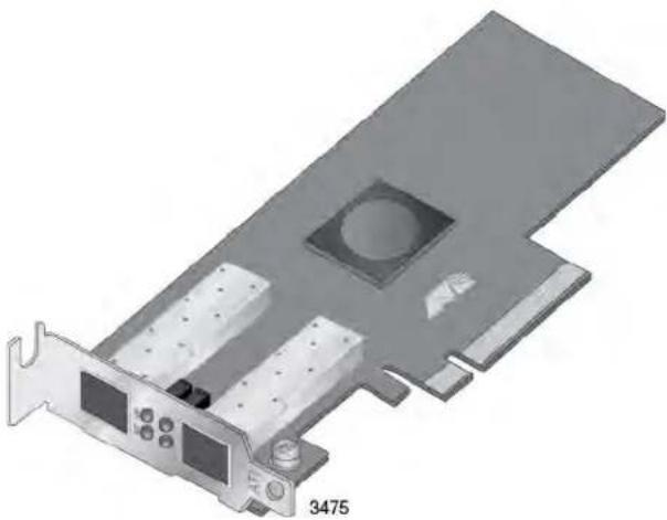
The AT-ANC10S/2 adapter, shown in Figure 1 on page 19, has two slots for SFP+ modules that operate at 10 Gbps in full duplex mode. You cannot change the speed or duplex mode of the transceiver slots. The maximum operating distance of an SFP+ slot will vary depending on the SFP+ transceiver and type of fiber optic cabling.
The adapter has an PCIe x8 motherboard bus connector.
natural_image
3D diagram of a computer RAM card with labeled ports and mounting bracket (no text or symbols beyond label)Figure 1. AT-ANC10S/2 Adapter
AT-ANC10S/2 Adapter Physical Description
The faceplate on the AT-ANC10S/2 adapter, shown in Figure 2 on page 19, has two slots for SFP+ transceivers, and four LEDs.
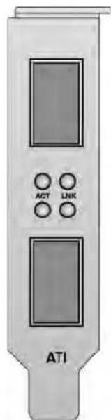
Figure 2. AT-ANC10S/2 Faceplate
The LEDs for the SFP+ slots are described in Table 2 on page 20.
Table 2. Network Link and Activity LEDs
| Port LED | LED State Network State | |
| ACT LED Off | The slot is empty or the | transceiver in the slot is not transmitting or receiving network traffic. |
| Blinking The transceiver | in the slot is transmitting or receiving network traffic. | |
| LNK LED Off | The slot is empty or the | transceiver has not established a link to a remote device. |
| Steady On The transceiver | her has established a link to a remote device. |
Features
The following features apply to the AT-ANC10S/2 adapter:
☐ Dual 10 Gbps MAC on the AT-ANC10S/2 adapter
☐ TCP segmentation offload
□ PXE v2.1 remote boot
□ Receive side scaling (RSS) for IPv4 and IPv6
□ Statistics gathering (SNMP MIB II)
☐ Comprehensive diagnostic and configuration software suite
☐ ACPI compliant power management
□ Virtual LANs-802.1q VLAN tagging
☐ Jumbo frames (up to 9 KB). The OS and link partner must support jumbo frames.
□ MSI, MSI-X
LiveLink™
☐ PCI Express x8 v3.0, 8 GTps-compliant
☐ PCI Express x8 v2.0, 5 GTps-compliant
☐ PCI Express x8 v1.1, 2.5 GTps-compliant
□ Smart Load Balancing Teaming
☐ IEEE Std 802.3ad teaming
Adaptive Interrupt Frequency
The adapter driver intelligently adjusts host interrupt frequency based on traffic conditions to increase overall application throughput. When traffic is light, the adapter driver interrupts the host for each received packet, minimizing latency. When traffic is heavy, the adapter issues one host interrupt for multiple, back-to-back incoming packets, preserving host CPU cycles.
ASIC with Embedded RISC Processor
The core control for the ANC10S/2 network adapter resides in a tightly integrated, high-performance ASIC. The ASIC includes a RISC processor. This functionality provides the flexibility to add new features to the card and adapts it to future network requirements through software downloads. This functionality also enables the adapter drivers to exploit the built-in host offload functions on the adapter as host operating systems are enhanced to take advantage of these functions.
Supported Operating Environments
The ANC10S/2 network adapter has software support for the following operating systems:
☐ Microsoft Windows Server 2008 (32-bit and 64-bit extended)
☐ Microsoft Windows Server 2008 R2
☐ Microsoft Windows Server 2012 and 2012 R2
☐ Microsoft Windows Server 2008 R2, 2012 and 2012 R2 Hyper-V
☐ Linux (32-bit and 64-bit extended)
□ Solaris x86
□ ESX Server (VMware)
Citrix XenServer
Chapter 2
Installing the Hardware
This chapter describes how to install the AT-ANC10S/2 in a PC and discusses the following topics:
☐ “Reviewing the Contents of Your Shipment” on page 24
☐ “Reviewing Safety Precautions” on page 25
☐ "Pre-Installation Checklist" on page 27
☐ “Installing the Standard Bracket on the Adapter” on page 28
☐ "Installing the Network Adapter Card" on page 30
☐ “Installing SFP+ Transceivers in the AT-ANC10S/2 Adapter” on page 34
Reviewing the Contents of Your Shipment
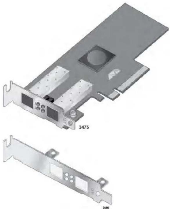
The AT-ANC10S/2 adapter comes with two brackets: a pre-installed low-profile bracket and a standard bracket. Refer to Figure 3.
AT-ANC10S/2 adapter with pre-installed low profile bracket.
Standard bracket.
natural_image
Technical illustration of a dual-chamber computer drive (no text or symbols on the diagram itself)Figure 3. Package Contents of the AT-ANC10S/2 Adapter
Inform your network supplier of any missing or damaged items. If you need to return the adapter, you must pack it in the original (or equivalent) packing material or the warranty will be voided. See “Contacting Allied Telesis” on page 15.
Reviewing Safety Precautions
Please review the following safety precautions before you begin to install a network adapter card.
Note
The 📌 indicates that a translation of the safety statement is available in a PDF document titled “Translated Safety Statements” on the Allied Telesis website at www.alliedtelesis.com/support/software. After you have accessed this website, enter the model number in the Search by Product Name box and then click Find to view the current list of documents.

Warning
This is a Class 1 Laser product. √L1

Warning
The fiber optic ports contain a Class 1 Laser device. When the ports are disconnected, always cover them with the provided plug. Exposed ports may cause skin or eye damage. L4

Warning
Do not stare into the laser beam. L2

Warning
Do not look directly at the fiber optic cable ends or inspect the cable ends with an optical lens. L6

Warning
Do not work on this equipment or cables during periods of lightning activity. E2
Note
All Countries: Install this product in accordance with local and National Electric Codes. E8

Warning
The adapter is being installed in a system that operates with voltages that can be lethal. Before you remove the cover of your system, you must observe the following precautions to protect yourself and to prevent damage to the system components.
- Remove any metallic objects or jewelry from your hands and wrists.
- Make sure to use only insulated or nonconducting tools.
- Verify that the system is powered OFF and unplugged before accessing internal components.
- Installation or removal of adapters must be performed in a static-free environment.
The use of a properly grounded wrist strap or other personal antistatic devices and an antistatic mat is strongly recommended.
E39
Pre-Installation Checklist
Before installing the adapter card, perform the following procedure:
- Verify that your system is using the latest BIOS.
- If your system is active, shut it down.
- When the system shutdown is complete, power OFF and unplug the power cord.
- Holding the adapter card by the edges, remove it from its shipping package and place it on an antistatic surface.
- Check the adapter for visible signs of damage, particularly on the card's edge connector.
Note
Do not install a damaged adapter. If the adapter is damaged, report it to Allied Telesis. See “Contacting Allied Telesis” on page 15.
Installing the Standard Bracket on the Adapter
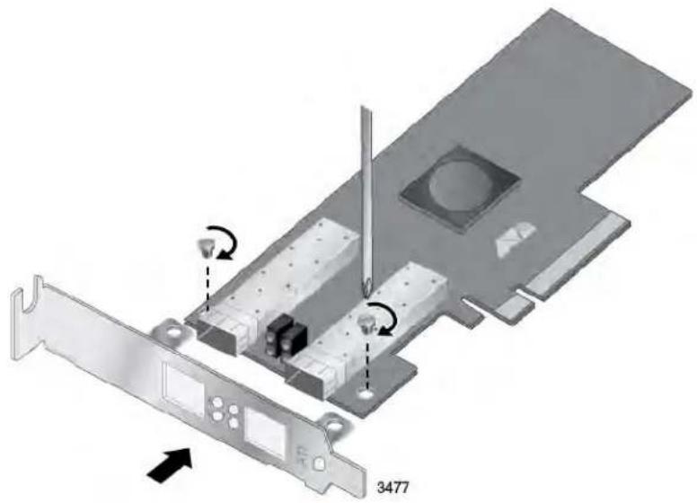
If you are installing AT-ANC10S/2 adapter in a computer that requires a standard bracket, you must replace the pre-installed low profile bracket on the adapter with the standard bracket. To install the standard bracket, perform the following procedure:
To replace the low-profile bracket with the standard bracket, do the following:
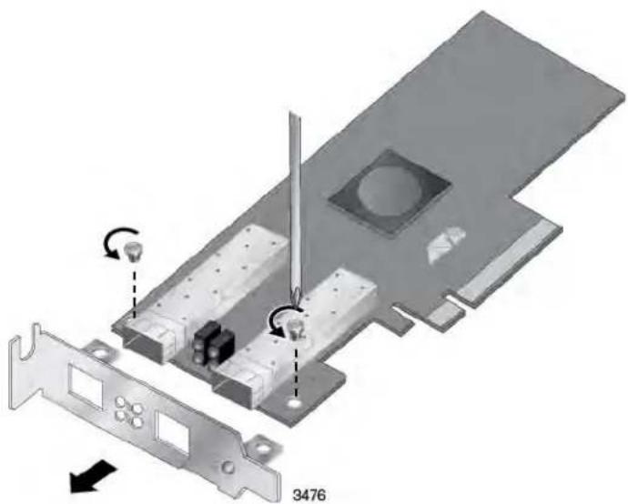
- Remove the screws that attach the bracket to the adapter. See Figure 4.
natural_image
3D diagram of a computer hardware component with labeled parts and directional arrows (no readable text or symbols)Figure 4. Removing the Low-profile Bracket
- Fit the standard bracket onto the adapter as shown in Figure 5 on page 29 and secure with the two screws.
natural_image
Diagram of a computer hardware component with labeled parts and directional arrows (no readable text or symbols)Figure 5. Installing the Standard Bracket
Installing the Network Adapter Card
The following installation instructions apply to most systems. For details about performing the tasks on your particular system, refer to the manuals that were supplied with your system.
Note
This procedure requires a Phillips-head screw.
Note
The AT-ANC10S/2 adapter requires a PCIe x8 PC.

Warning
The adapter is being installed in a system that operates with voltages that can be lethal. Before you remove the cover of your system, you must observe the following precautions to protect yourself and to prevent damage to the system components.
- Remove any metallic objects or jewelry from your hands and wrists.
- Make sure to use only insulated or nonconducting tools.
- Verify that the system is powered OFF and unplugged before accessing internal components.
- Installation or removal of adapters must be performed in a static-free environment.
The use of a properly grounded wrist strap or other personal antistatic devices and an antistatic mat is strongly recommended.
E39
To install the adapter, do the following:
- Review the "Pre-Installation Checklist" on page 27 and "Reviewing Safety Precautions" on page 25.
Before installing the adapter, verify that the computer is powered OFF and that the power cord is unplugged from the power outlet. You should also be sure to follow all proper electrical grounding procedures.
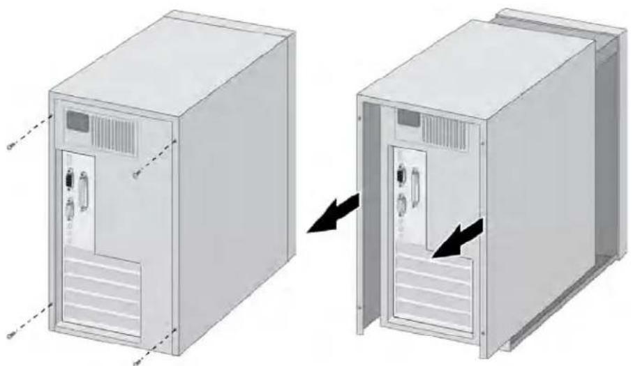
- Remove the system cover. Refer to Figure 6 on page 31.
natural_image
Diagram showing two views of a server cabinet with doors and ventilation grilles, one being removed (no text or symbols present)Figure 6. Removing the PC Cover
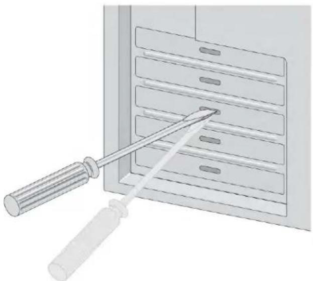
- Select an empty, non-shared PCIe slot and remove the faceplate.
Note
If you cannot locate or do not know how to find an appropriate PCIe slot, refer to the documentation that came with your system.
Keep the faceplate in a safe place. You may need it for future use. See Figure 7.
natural_image
Illustration of a screwdriver inserted into a rack with multiple slots (no text or symbols)Figure 7. Removing the Faceplate From PCIe Slot
-
Remove the network adapter card from the shipping package and store the packaging material in a safe location.
-
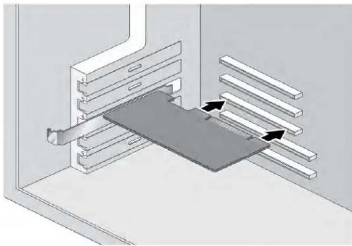
Applying even pressure at both corners of the card, push the adapter card until it is firmly seated in the appropriate PCIe slot. Refer to Figure 8. Make sure the card is securely seated.
natural_image
3D diagram of a mechanical assembly with a central component and parallel plates, showing directional arrows (no text or symbols)Figure 8. Inserting the Adapter with a High-profile Bracket

Caution
Do not use excessive force when seating the card, because this may damage the system or adapter. If the card resists seating, remove it from the system, realign it, and try again. E47
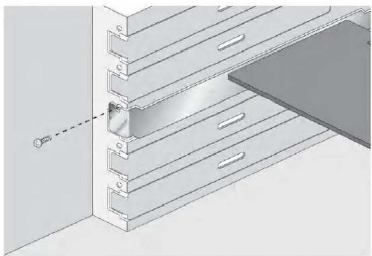
- Secure the network adapter card to the chassis with a Phillips-head screw (not provided). See Figure 9 on page 33.
natural_image
Technical illustration of a mechanical assembly with layered components and a dashed line indicating a connection point (no text or symbols present)Figure 9. Securing the Adapter with a High-profile Bracket
- Replace the system's cover and secure it with the screws removed in step 2.
- Go to "Installing SFP+ Transceivers in the AT-ANC10S/2 Adapter" on page 34.
- Power on the system.
Installing SFP+ Transceivers in the AT-ANC10S/2 Adapter
Here are the guidelines to installing and cabling SFP+ transceivers in the AT-ANC10S/2 adapter:
☐ SFP+ transceivers can be hot-swapped while the adapter is powered on. However, you should always disconnect the fiber optic cables first before removing a transceiver.
☐ You should install a transceiver in the adapter before connecting the fiber optic cable.
☐ Fiber optic transceivers are dust sensitive. Always keep the plug in the optical bores when a fiber optic cable is not installed, or when you store the transceiver. When you do remove the plug, keep it for future use.
☐ Unnecessary removal and insertion of a transceiver can lead to premature failure.
☐ The connector on the fiber topic cable should fit snugly into the port on the adapter, and the tab should lock the connector into place.
☐ Do not remove the dust cover from a fiber optic port until you are ready to connect a fiber optic cable. Dust contamination can adversely affect the operation of a fiber optic port.

Warning
A transceiver can be damaged by static electricity. Be sure to observe all standard electrostatic discharge (ESD) precautions, such as wearing an antistatic wrist strap, to avoid damaging the device. E86

Warning
The fiber optic ports contain a Class 1 laser device. When the ports are disconnected, always cover them with the provided plug. Exposed ports may cause skin or eye damage. ∞ L4
Note
The cable specifications for the SFP+ transceivers are found in the installation guides that ship with the devices.
Note
For information about cleaning a fiber optic connector on the AT-ANC10S adapter, see Appendix B “Cleaning Fiber Optic Connectors” on page 119.
Chapter 3
Installing Broadcom Boot Agent Driver Software
This chapter provides information about how to install the Broadcom Boot Agent Driver Software and discusses the following topics:
☐ "Overview" on page 36
☐ "Setting Up MBA in a Client Environment" on page 37
☐ “Setting Up MBA in a Server Environment: Red Hat Linux PXE Server” on page 38
Overview
The AT-ANC10S/2 network adapter supports Preboot Execution Environment (PXE). Multi-Boot Agent (MBA) is a software module that allows your network computer to boot with the images provided by remote servers across the network. The Broadcom MBA driver complies with PXE 2.1 code.
The MBA module operates in a client/server environment. A network consists of one or more boot servers that provide boot images to multiple computers through the network. The Broadcom implementation of the MBA module has been tested successfully in the following environments:
☐ Linux Red Hat PXE Server. Broadcom PXE clients are able to remotely boot and use network resources (NFS mount, and so forth) as well as perform Linux installations. In the case of a remote boot, the Linux universal driver binds seamlessly with the Broadcom Universal Network Driver Interface (UNDI) and provides a network interface in the Linux remotely-booted client environment.
Intel APITEST. The Broadcom PXE driver passes all API compliance test suites.
☐ Windows Deployment Service (WDS). For Windows Server 2003 SP2, RIS was replaced by WDS, which offers a Broadcom PXE client to install Windows operating systems, including Windows Vista, Windows Server 2008 and Windows Server 2008 R2.
Setting Up MBA in a Client Environment
| Setting up a Multiple Boot Agent (MBA) in a client environment involves the following procedures: | |
| ☐ “Enabling the MBA Driver” on page 37 | |
| ☐ “Disabling the MBA Driver” on page 37 | |
| ☐ “Setting Up the BIOS” on page 37 | |
| Enabling the MBA Driver | To enable MBA, perform the following procedure: |
| 1. Power on the system with the card installed. | |
| 2. When prompted, enter CTRL-S to enter the NIC setup menu. | |
| 3. Set the pre-boot to PXE, which is the default setting. | |
| Disabling the MBA Driver | To disable MBA, perform the following procedure: |
| 1. Power on the system with the card installed. | |
| 2. When prompted, enter CTRL-S to enter the NIC setup menu. | |
| 3. Set the pre-boot to None. |
Note
If you set PXE to None on all the ports on the adapter, you will not be able to access the CTRL-S prompt and NIC setup menu.
Note
The message prompting you to press CTRL+S is displayed only once even if the computer has more than one AT-ANC10S Interface Adapter. After you press CRTL+S, the Broadcom Comprehensive Control Manager displays all the Broadcom devices that are installed in the computer and that you can configure.
Setting Up the BIOS
To boot from the network with the MBA, make the MBA enabled adapter the first bootable device under the BIOS. This procedure depends on the system BIOS implementation. Refer to the user manual for the system BIOS implementation for instructions.
Setting Up MBA in a Server Environment: Red Hat Linux PXE Server
The Red Hat Enterprise Linux distribution has PXE Server support. It allows users to remotely perform a complete Linux installation over the network. The distribution comes with the boot images boot kernel (vmlinuz) and initial ram disk (initrd), which are located on the Red Hat disk#1:
/images/pxeboot/vmlinuz /images/pxeboot/initrd.img
Refer to the Red Hat documentation for instructions on how to install PXE Server on Linux.
However, the Initrd.img file distributed with some Red Hat Enterprise Linux distributions does not have a Linux network driver for the AT-ANC10S/2 network adapter. These distributions require a driver disk for drivers that are not part of the standard distribution. You download the driver software files from the Allied Telesis web site.
Chapter 4
Installing the Linux Drivers
The procedures in this chapter explain how to install the Linux drivers for the adapter.
This chapter discusses the following topics:
☐ "Overview" on page 40
☐ “Installing Linux Driver Software” on page 41
Overview
This chapter discusses the Linux drivers for the AT-ANC10S/2 network adapter and describes how to install them. For a description of the drivers, see Table 3.
Table 3. Linux Driver for the AT-ANC10S/2 Network Adapter
| Linux Driver Description | |
| bnx2x Indicates the | Linux drivers for the AT-ANC10S/2 network adapter. The bnx2x driver is the networking driver. |
bnx2x Driver Limitations
The current version of the driver has been tested on 2.4.x kernels (starting from 2.4.24) and all 2.6.x kernels. The driver may not compile on kernels older than 2.4.24.
Testing is concentrated on i386 and x86_64 architectures. Only limited testing has been done on other architectures. You may need to make minor changes to some source files and the Makefile on some kernels.
Packaging
The Linux driver is released in the packaging formats shown in Table 4. The NetXtreme2 package contains the bnx2x (10 Gb network adapter) and drivers for source RPM and compressed tar.
Table 4. Linux Driver Packaging
| Format | bnx2x Driver |
| Source RPM Netxtreme2-version.src.rpm | |
| Compressed TAR Netxtreme2-version.tar.gz | |
| Supplemental TAR Netxtreme2_sup-version.tar.gz | |
Identical source files to build the driver are included in both RPM and TAR source packages. The supplemental tar file contains additional utilities such as patches and driver diskette images for network installation.
Installing Linux Driver Software
There are two ways to install the Linux driver software — from the Source RPM Package or by building the driver from the source TAR file. See the following sections:
☐ "Installing the Source RPM Package" on page 41
☐ “Building the Driver from the Source TAR File” on page 42
Note
If a bnx2x driver is loaded and you update the Linux kernel, you must recompile the driver module if it was installed using the source RPM or the TAR package.
Installing the Source RPM Package
The procedure in this section describes how to install the Source RPM Package.
To install the Source RPM Package, do the following:
- Enter the following command:
rpm -ivh netxtreme2-version.src.rpm - Change the directory to the RPM path and build the binary driver for your kernel (the RPM path is different for each Linux distribution):
cd /usr/src/redhat,OpenLinux,turbo,packages,rpm ...
rpm -bb SPECS/netxtreme2.spec
or
rpmbuild -bb SPECS/netxtreme2.spec (for RPM version 4.x.x)
Note
The error message error: cannot create %sourcedir / usr/src/redhat/SOURCES is displayed if the rpm-build package is not installed. To resolve the problem, locate the rpm-build package on the Linux installation media and install it using the following command:
rpm -ivh rpm-build-version.arch.rpm
Then complete the installation of the source RPM.
- Install the newly built package which includes the driver and man page:
rpm -ivh RPMS/i386/bnx2x-version.arch.rpm
If you are installing over an existing distribution that may already contain an older version of the driver, the —force option is needed.
Depending on the kernel, the driver is installed to one of the following paths:
For 2.4.x kernels
/lib/modules/kernel_version/kernel/drivers/net/bnx2x.o
For 2.6.x kernels:
/lib/modules/kernel_version/kernel/drivers/net/bnx2x.ko
- To load the driver, enter one of the following commands:
insmod bnx2x
or
modprobe bnx2x
To configure the network protocol and address, refer to the documentation provided with your operating system.
Building the Driver from the Source TAR File
This procedure describes how to build the bnx2x Linux driver from the Source TAR file.
Building the bnx2x Driver
To build the bnx2x Linux driver from the Source TAR file, do the following:
- Create a directory and extract the TAR files to the following directory:
tar xvzf netxtreme2-version.tar.gz
- Build the driver bnx2x.ko (or bnx2x.o) as a loadable module for the running kernel. Enter the following commands:
cd bnx2x-version/src make
- Test the driver by loading it (if necessary, first unload the existing driver). Enter the following commands:
rmmod bnx2x insmod bnx2x.o modprobe crc32 && insmod bnx2x.o
or, for Linux 2.6 kernels:
rmmod bnx2x
insmod bnx2x.ko
- Install the driver and man page by entering the following command:
make install
Note
See the “Installing the Source RPM Package” on page 41 for the location of the installed driver.
Unloading the Linux Driver
To configure the network protocol and address after building the driver, refer to the manuals supplied with your operating system.
You can unload, or remove, the Linux Driver from an RPM or TAR installation. See the following:
☐ “Unloading the Driver from an RPM Installation” on page 43
☐ “Unloading the Driver from a TAR Installation” on page 43
Unloading the Driver from an RPM Installation
This section describes how to unload, or remove, a Linux driver from an RPM installation.
Note
On 2.6 kernels, it is not necessary to bring down the eth# interfaces before unloading the driver module.
To unload the driver, use ifconfig to bring down all eth# interfaces opened by the driver, and then enter:
rmmod bnx2x
If the driver was installed using the rpm command, enter the following command to remove it:
rpm -e netxtreme2
Unloading the Driver from a TAR Installation
If the driver was installed using make install from the tar file, manually delete the bnx2x.o or bnx2x.ko driver file from the operating system. See "Installing the Source RPM Package" on page 41 for the location of the installed driver.
Patching PCI Files (Optional)
This is an optional procedure that describes how to patch PCI files for identification by other vendors.
For hardware detection utilities, such as Red Hat kudzu, to properly identify bnx2x supported devices, you may need to update a number of files containing PCI vendor and device information.
Apply the updates by running the scripts provided in the supplemental tar file. For example, on Red Hat Enterprise Linux, apply the updates by entering the following commands:
./patch_pcitbl.sh /usr/share/hwdata/pcitable
pci.updates
/usr/share/hwdata/pcitable.new bnx2x
./patch_pciids.sh /usr/share/hwdata/pci.ids
pci.updates
/usr/share/hwdata/pci.ids.new
Next, back up the old files and rename the new files by entering the following copy commands:
cp /usr/share/hwdata/pci.ids /usr/share/hwdata/ old.pci.ids
cp /usr/share/hwdata/pci.ids.new /usr/share/hwdata/pci.ids
cp /usr/share/hwdata/pcitable /usr/share/hwdata/ old.pcitable
cp /usr/share/hwdata/pcitable.new /usr/share/hwdata/pcitable
Network Installations
For network installations through NFS, FTP, or HTTP (using a network boot disk or PXE), a driver disk that contains the bnx2x driver may be needed. The driver disk images for the most recent Red Hat and SuSE versions are included. Boot drivers for other Linux versions can be compiled by modifying the Makefile and the make environment. Further information is available from the Red Hat website at www.redhat.com.
Setting Optional Properties for the bnx2x Driver
The disable_msi optional property can be used as a command line argument to the insmod or modprobe command. The property can also be set in the modprobe.conf command. See the man page for more information.
All other driver settings can be queried and changed using the ethtool utility. See the ethtool man page for more information. The ethtool settings do not persist across a reboot or module reload. In addition, you can put the ethtool commands in a startup script, such as /etc/rc.local, to
preserve the settings across a reboot.
Note
Some combinations of property values may conflict and result in failures. The driver cannot detect all conflicting combinations.
This property is used to disable Message Signal Interrupts (MSI). The property is valid only on 2.6 kernels that support MSI. This property cannot be used on 2.4 kernels. By default, the driver enables MSI if it is supported by the kernel. It runs an interrupt test during initialization to determine if MSI is working. If the test passes, the driver enables MSI. Otherwise, it uses legacy INTx mode. To set the bnx2x driver, enter one of the following:
insmod bnx2x.ko disable_msi=1
or
modprobe bnx2x disable_msi=1
Checking the bnx2x Driver Defaults
The bnx2x driver default values are listed in Table 5:
Table 5. Default Values for the bnx2x Driver
| Parameter | Default Value |
| Speed 10Gbps Full Duplex | |
| Flow Control Autonegotiation with RX and TX advertised | |
| MTU 1500 (range is 46–9000) | |
| RX Ring Size 255 (range is 0–4080) | |
| RX Jumbo Ring Size 0 (range 0–163) | 20) adjusted by the driver based on MTU and RX Ring Size |
| TX Ring Size 255 (range is | (MAX SKB_FRAGS+1)–255). MAX SKB_FRAGS varies on different kernels and different architectures. On a 2.6 kernel for x86, MAX SKB_FRAGS is 18. |
| Coalesce RX Microseconds 18 (range is 0–1023) | |
| Coalesce RX Microseconds IRQ 18 | (range is 0–1023) |
| Coalesce RX Frames 6 (range is 0–255) | |
| Coalesce RX Frames IRQ 6 (range is 0–255) | |
| Coalesce TX Microseconds 80 (range is 0–1023) | |
| Coalesce TX Microseconds IRQ 80 (range is 0–1023) | |
| Coalesce TX Frames 20 (range is 0–255) | |
| Coalesce TX Frames IRQ 20 (range is 0–255) | |
| Coalesce Statistics Microseconds 999936 (approximately 1 second)(range is 0–16776960 in increments of 256) | |
| MSI Enabled (if supported by the 2.6 kernel and the interrupt test passes) | |
| TSO Enabled (on 2.6 kernels) | |
| WoL Not supported. | |
Checking Driver Messages
The following are the most common sample messages that may be logged in the /var/log/messages file for the bnx2x driver. Use dmesg -n
□ Driver Sign on
□ NIC Detected
□ Link Up and Speed Indication
□ Link Down Indication
☐ MSI enabled successfully
Teaming with Channel Bonding
With the Linux drivers, you can team adapters together using the bonding kernel module and a channel bonding interface. For more information, see the Channel Bonding information in your operating system documentation.
Statistics You can view detailed statistics and configuration information using the ethtool utility. See the ethtool man page for more information.
Chapter 5
Installing the Windows Drivers
This chapter provides procedures to install and remove the driver software for all of the Windows Operating Systems supported by the AT-ANC10S/2 adapter. In addition, it describes how to display and change adapter properties including power management options. This chapter discusses the following topics:
☐ "Supported Versions of Microsoft Windows" on page 48
☐ “Installing the Windows Driver Software” on page 49
☐ “Removing the Device Drivers” on page 57
Supported Versions of Microsoft Windows
Table 6 lists the versions of Microsoft Windows supported by the adapter.
Table 6. Supported Versions of Microsoft Windows
| Version of Microsoft Windows Operating System | AT-ANC10S/2 |
| Windows Vista 32/64 - | |
| Windows 7 32/64 - | |
| Windows Server 2003 32/64 - | |
| Windows Server 2008 32/64 Yes | |
| Windows Server 2008 R2 Yes | |
| Windows Server 2012 Yes | |
| Windows Server 2012 R2 Yes |
Installing the Windows Driver Software
This chapter describes how to install all of the following Windows Operating Systems:
□ Microsoft Windows Server 2008 (32-bit and 64-bit extended)
□ Microsoft Windows Server 2008 R2
☐ Microsoft Windows Server 2012 and 2012 R2
The Windows driver software for all of the Windows Operating Systems is available on the Allied Telesis website at www.alliedtelesis.com/support/software. After you have accessed this website, enter the model number in the Search by Product Name box and then click Find to display the current list of software drivers.
There are two methods to install the software drivers on all of the Windows Operating Systems: the Installer and Silent installation. The Installer uses a graphical interactive mode. The Silent Installation is a command-line interface for unattended installation. See the following sections:
☐ "Using the Installer" on page 50
☐ "Using Silent Installation" on page 54
Note
These instructions are based on the assumption that your adapter was not factory installed. If your controller was installed at the factory, the driver software has been installed for you.
Note
Before installing the driver software, verify that the Windows operating system has been upgraded to the latest version with the latest service pack applied.
Note
You must physically install a network device driver before the AT-ANC10S/2 network adapter can be used with your Windows Operating System. There is no installation CD. You must download the drivers from the Allied Telesis website at www.alliedtelesis.com/support/software. After you have accessed this website, enter the model number in the Search by Product Name box and then click Find to view the current list of documents and drivers.
Using the Installer
Please read the following information before installing the driver:
☐ Microsoft Windows Operating Systems do not have wizards but will attempt to install the driver automatically. These processes should be cancelled. Only the installer should be used to install the driver.
☐ Do not use any Microsoft Windows wizards to install the driver. All wizards and informational boxes should be closed or cancelled before running the installer.
The Installer has a graphical interactive installation mode. To install the AT-ANC10S/2 driver on a Windows Operating System, do the following:
- From the driver directory, select the setup.exe file and Run.
The Broadcom NetXtreme II Driver Installer - InstallShield Wizard Page is displayed. See Figure 10 on page 51.
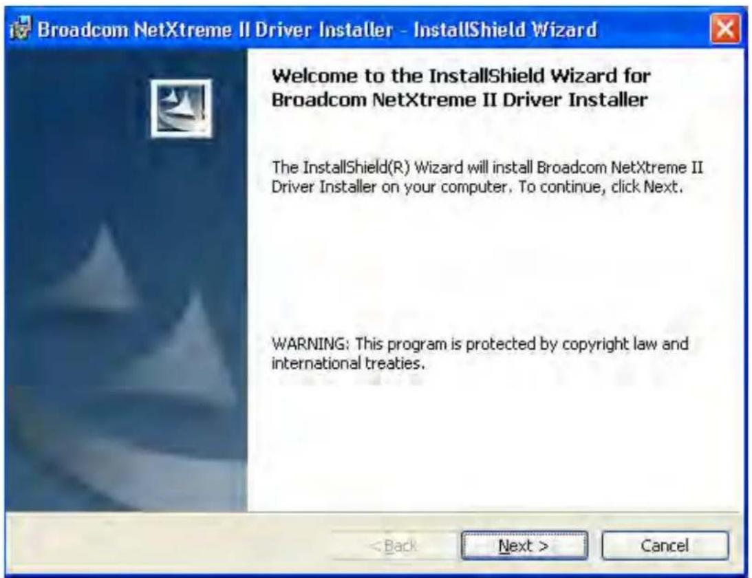
Figure 10. Broadcom NetXtreme II Driver Installer - InstallShield Wizard Page
- Click Next to continue.
The License Agreement Page is displayed. See Figure 11 on page 52.
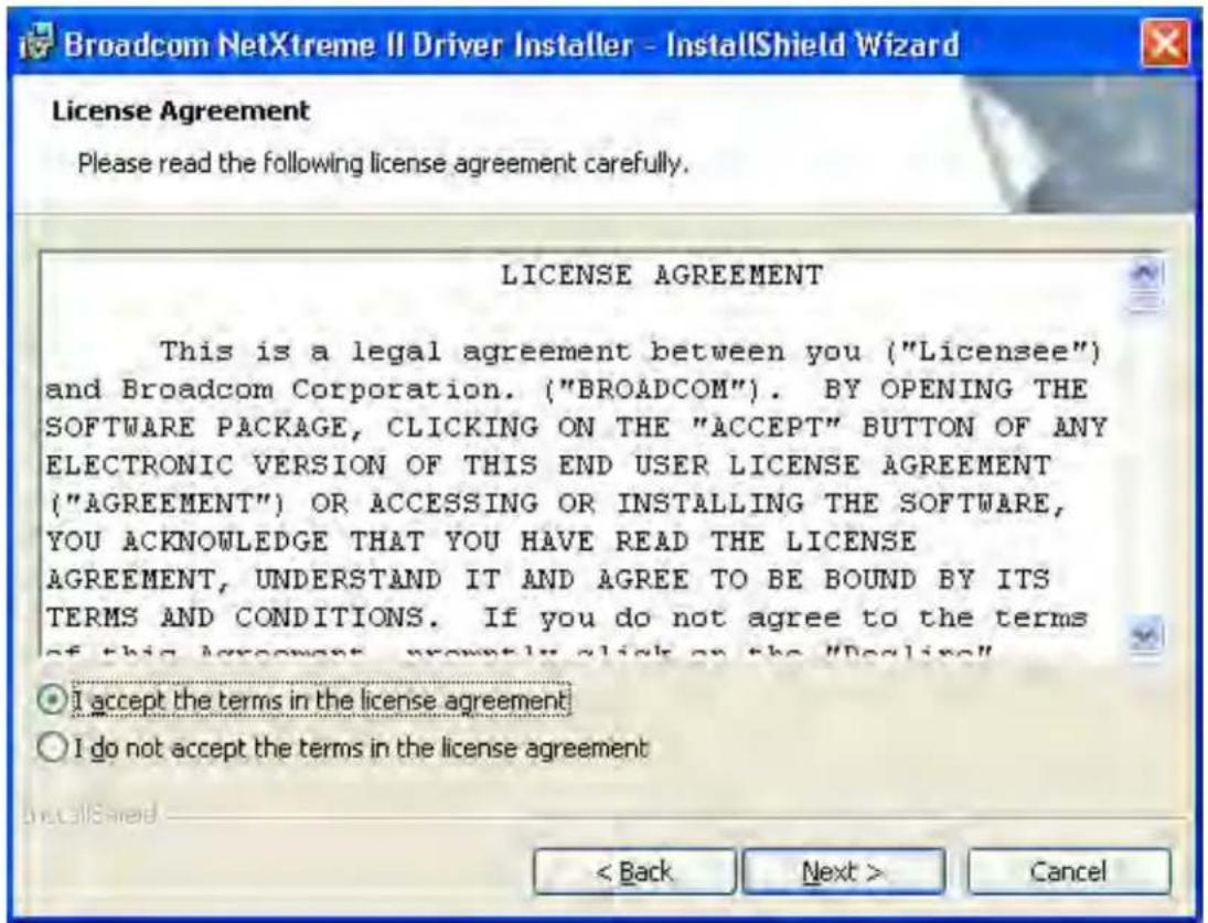
Figure 11. License Agreement Page
- After you review the license agreement, click I accept the terms in the license agreement and then click Next to continue.
The Ready to Install the Program Page is displayed. See Figure 12 on page 53.
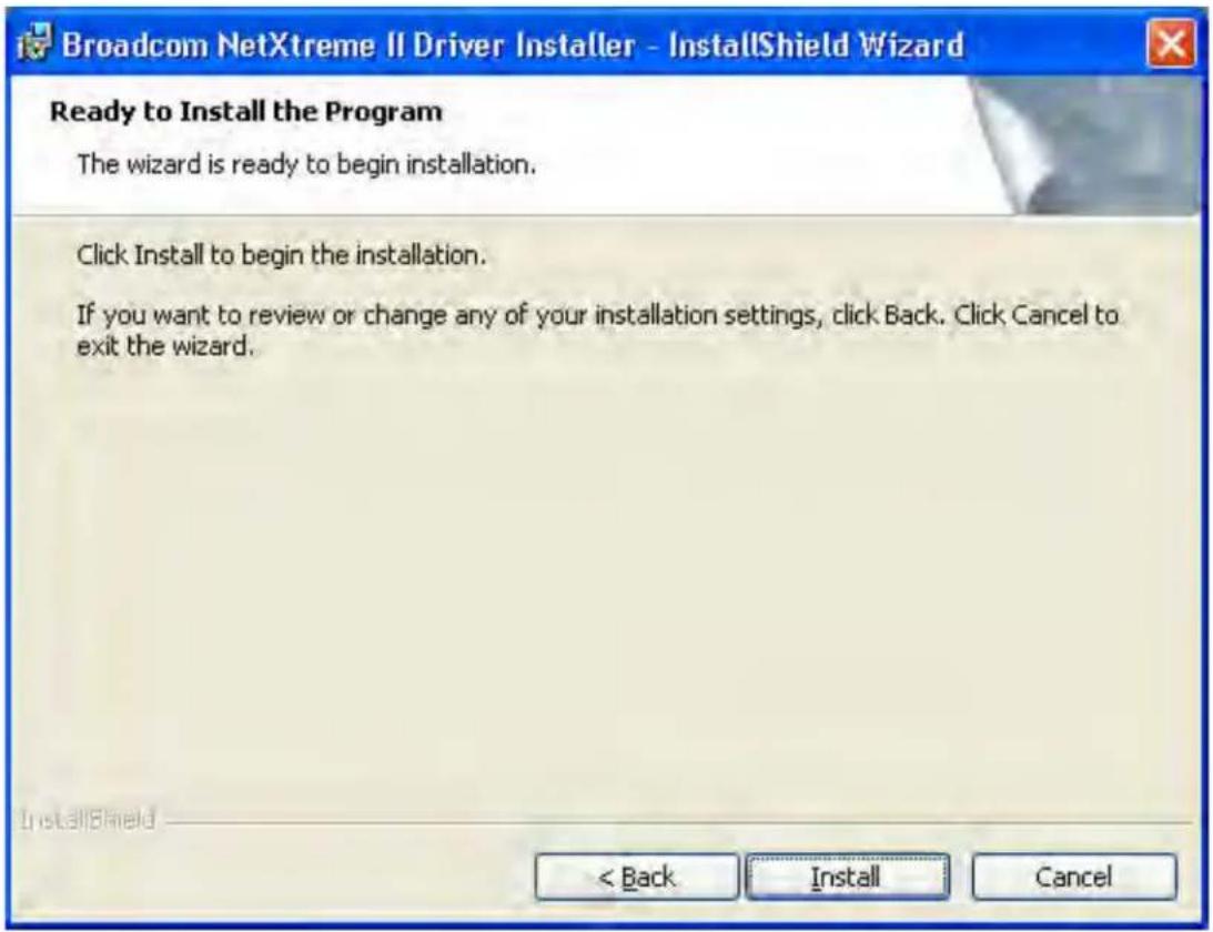
Figure 12. Ready to Install the Program Page
4. Click Install.
The InstallShield Wizard Completed Page is displayed. See Figure 13 on page 54.
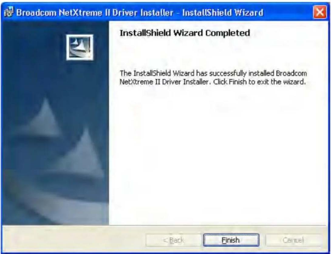
Figure 13. InstallShield Wizard Completed Page
- Click Finish to close the wizard.
- The installer determines if a system restart is necessary. Follow the on-screen instructions.
Using Silent Installation
Silent installation provides a command-line silent mode which allows for unattended installation. This section discusses the various ways to perform a silent installation on all of the Windows Operating Systems supported by the AT-ANC10S/2 adapter. See the following sections:
☐ "Performing a Silent Install" on page 55
☐ “Performing a Silent Install and Creating a Log File” on page 55
☐ "Performing a Silent Upgrade" on page 55
☐ "Performing a Silent Uninstall" on page 55
☐ "Performing a Silent Reinstall" on page 56
Note
All commands are case sensitive.
Note
User must "Run as Administrator" for Vista when using "msiexec" for "silent" install or uninstall procedures.
Note
For detailed instructions and information about unattended installs, refer to the Silent.txt file in the DrvInst folder.
Performing a Silent Install
To perform a silent install from within the installer source folder, enter one of the following:
setup /s /v/qn
or
msiexec /i "BDrv5706.msi" /qn
Performing a Silent Install and Creating a Log File
To perform a silent install and create a log file at (f:\1testlog.txt), enter:
setup /s /v"/qn /L f:\ltestlog.txt"
Performing a Silent Upgrade
To perform a silent upgrade from within the installer source folder, enter:
setup /s /v/qn
Performing a Silent Uninstall
There are two ways to perform a silent uninstall— from the installer source folder or from the any folder.
In some circumstances, you must reboot your system before uninstallation can continue. If you used REBOOT=ReallySuppress to suppress the reboot, the uninstallation may be suspended. In this case, you need to reboot manually for the uninstallation to continue.
To perform a silent uninstall from within the installer source folder, enter:
msiexec /x "BDrv5706.msi" /qn
To perform a silent uninstall from any folder, enter:
msiexec /x " {F0DA8A3F-1457-419E-96F4-235DD3EF41E1}" /qn
Note
The hexadecimal number above may differ from your current installer. Check the Key name in HKLM\Software\Microsoft\Windows\CurrentVersion\Uninstall for the correct hexadecimal number.
Performing a Silent Reinstall
To perform a silent reinstall of the same installer, enter:
setup /s /v"/qn REINSTALL=ALL"
Note
Use REINSTALL switch only if the same installer is already installed on the system. If you are upgrading an earlier version of the installer, use setup /s /v/qn as described above.
Removing the Device Drivers
This section discusses how to remove the device drivers.
Note
Windows Server 2008 and Windows Server 2008 R2 provide the Device Driver Rollback feature that replaces a device driver with one that was previously installed. However, the complex software architecture of the AT-ANC10S/2 network adapter may present problems if the rollback feature is used on one of the individual components. Therefore, Allied Telesis recommends that changes to driver versions be made only through the use of a driver installer.
To remove the device drivers, do the following:
- In Control Panel, double-click Add or Remove Programs.
- Click Broadcom NetXtreme II GigE Driver Installer, and then click Remove. Follow the on screen prompts.
- Click Yes to restart your system.
- or -
- Click No to restart your system at a later time.
- Click OK to acknowledge that the installation has been suspended.
The uninstallation of the driver is postponed until the next restart of your system.
Chapter 5: Installing the Windows Drivers
Chapter 6
Setting Advanced Properties
For all of the Windows operating systems, you access the Windows Advanced Properties from the Advanced Tab. Although the default values of the Advanced Properties are appropriate in most cases, you can change any of the available options to meet the requirements of your system.
This chapter discusses the following topics:
☐ “Advanced Features” on page 60
☐ “Accessing the Advanced Tab” on page 62
☐ “Modifying the Advanced Properties” on page 65
Advanced Features
Table 7 lists the advanced network adapter features in Microsoft Windows that are supported by the AT-ANC10S/2 Adapter. Default values are marked with an asterisk.
Table 7. Advanced Features in Microsoft Windows Supported by the AT-ANC10S/2 Adapter
| Feature | Windows Server2008 32/64 | Windows Server2008 R2 | Windows Server2012 and 2012 R2 |
| Encapsulated Task Offload | -- Disabled | Enabled* | |
| Flow Control Auto* | DisabledRX and TX EnabledRX EnabledTX Enabled | Auto*DisabledRX and TX EnabledRX EnabledTX Enabled | Auto*DisabledRX and TX EnabledRX EnabledTX Enabled |
| Interrupt Moderation DisabledEnabled* | DisabledEnabled* | DisabledEnabled* | |
| Jumbo Packet 1514* | 408890149614 | 1514*408890149614 | 1514*408890149614 |
| Large Send Offload V2 IPv4 | DisabledEnabled* | DisabledEnabled* | DisabledEnabled* |
| Large Send Offload V2 IPv6 | DisabledEnabled* | DisabledEnabled* | DisabledEnabled* |
| Locally Administered Address | No value* No value* No value* | ||
| Maximum Number of RSS Queues | 16248* | 16248* | 1624*8 |
| Priority and VLAN Priority/VLAN DisabledPriority/VLAN Enabled*Priority EnabledVLAN Enabled | Priority/VLAN DisabledPriority/VLAN Enabled*Priority EnabledVLAN Enabled | Priority/VLAN DisabledPriority/VLAN Enabled*Priority EnabledVLAN Enabled | |
| Quality of Service -- Disabled | Enabled* | ||
Table 7. Advanced Features in Microsoft Windows Supported by the AT-ANC10S/2 Adapter
| Feature | Windows Server 2008 32/64 | Windows Server 2008 R2 | Windows Server 2012 and 2012 R2 |
| Receive Buffers (0=Auto) | 0* to 3000 in increments of 50 | 0* to 3000 in increments of 50 | 0* to 3000 in increments of 50 |
| Receive Side Scaling | Disabled Enabled* | Disabled Enabled* | Disabled Enabled* |
| Recv Segment Coalescing (IPv4) | -- Disabled | Enabled* | |
| Recv Segment Coalescing (IPv6) | -- Disabled | Enabled* | |
| Speed and Duplex 1 Gb | Full 10 Gb-Full* | Full 10 Gb-Full* | Full 10 Gb-Full* |
| SRIOV -- Disabled | Enabled* | ||
| Starting RSS CPU 0* to 63 0* to 63 0* to 63 | |||
| TCP Connection Offload (IPv4) | Not supported. Not supported. Not supported. | ||
| TCP Connection Offload (IPv6) | Not supported. Not supported. Not supported. | ||
| TCP/UDP Checksum Offload (IPv4) | Disabled RX and TX Enabled* RX Enabled TX Enabled | Disabled RX and TX Enabled* RX Enabled TX Enabled | Disabled RX and TX Enabled* RX Enabled TX Enabled |
| TCP/UDP Checksum Offload (IPv6) | Disabled RX and TX Enabled* RX Enabled TX Enabled | Disabled RX and TX Enabled* RX Enabled TX Enabled | Disabled RX and TX Enabled* RX Enabled TX Enabled |
| Transmit Buffers (0=Auto) | 0* to 5000 in increments of 50 | 0* to 5000 in increments of 50 | 0* to 5000 in increments of 50 |
| Virtual Machine Queues | - Enabled* | Disabled | Enabled* Disabled |
| VLAN ID 0* to 4094 0* to 4094 | |||
Accessing the Advanced Tab
To modify the configuration properties of the Windows Operating systems, you must access the Advanced Tab. Depending on your operating system, there are several ways to do this. See the following procedures:
☐ "Selecting the Advanced Tab in Windows Server 2008 or Windows Server 2008 R2" on page 62
☐ "Selecting the Advanced Tab in Windows Server 2012" on page 63
Selecting the Advanced Tab in Windows Server 2008 or Windows Server 2008 R2
To select the Advanced Tab in the Windows Server 2008 or Windows Server 2008 R2 Operating System, do the following:
- Select the Start button. See Figure 14.
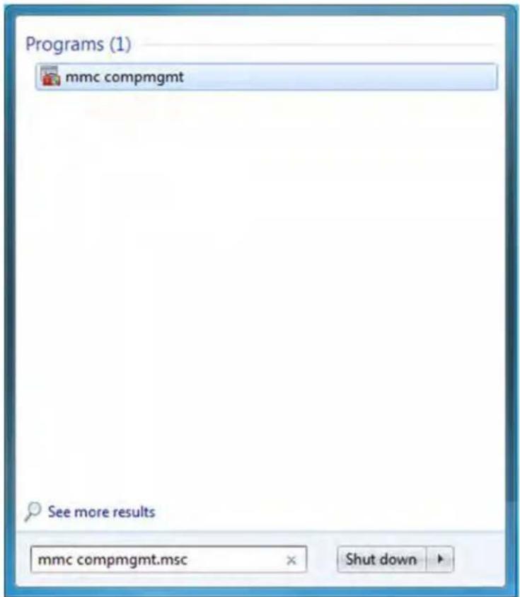
Figure 14. Windows Server 2008 and Windows Server 2008 R2 Search Box
- Enter the following command:
mmc devmgmt.msc
The Device Manager window is displayed. See Figure 15.
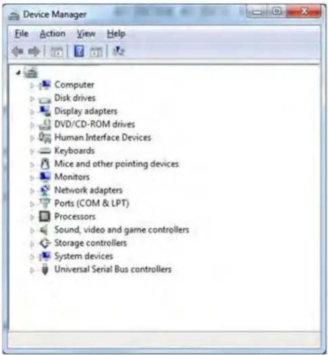
Figure 15. Device Manager Window
- Open the Network Adapters folder.
The list of installed adapters is displayed.
- Right click on the BCM57810NetXtreme II 10 GigE adapter.
The adapter window is displayed.
- Select the Advanced tab.
Selecting the Advanced Tab in Windows Server 2012
To access the Advanced Tab in the Windows 2012 Server Operating System, perform the following procedure.
- Right click on the Windows logo in the bottom left corner of the Desktop.
See Figure 16 on page 64 for an example of the Windows Server 2012 Desktop.
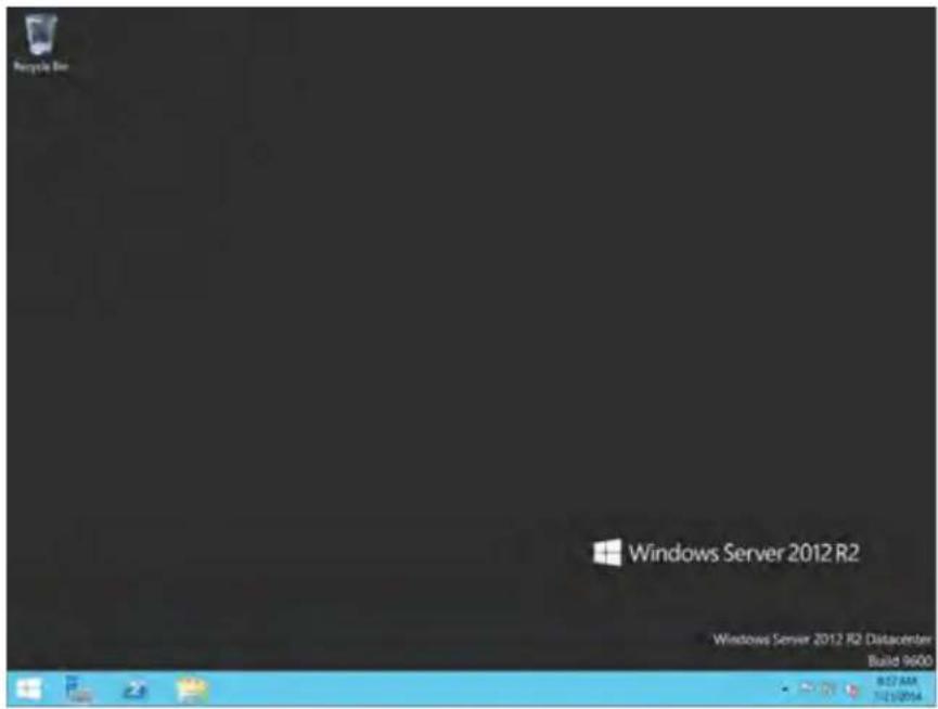
Figure 16. Windows Server 2012 Desktop
- From the Start Menu, select Run.
The Windows Server 2012 Run window is displayed. See Figure 17.
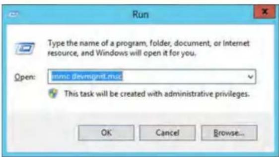
Figure 17. Windows Server 20112 Run Window
- Enter the following command in the Run window:
mmc devmgmt.msc
The Device Manager window is displayed. See Figure 15 on page 63.
-
Expand the Network Adapters folder.
-
Right click on the Broadcom BCM57810 NetXtreme II 10 GigE and select Properties from the menu: The adapter window is displayed.
Modifying the Advanced Properties
After you have installed the driver software, you can use Table 8 to verify or change the adapter properties:
Note
After you upgrade the driver software, the Advanced Properties may change.
Note
The configuration steps in the table may differ slightly if the "Classic Start Menu" is set on your computer.
Table 8. Advanced Features in Microsoft Windows
| Feature Description | Configuration Steps | |
| Encapsulated Task Offload | Allows for task offload capabilities when using Hyper-V Virtualized Network (HVN) functions | 1. In Microsoft Windows, right-click the Network Adapter in Network Connections and, then click Properties.2. Click the Configure button and then the Advanced tab.3. Set the desired Encapsulated Task Offload value. |
| Flow Control Enables | or disables the receipt or transmission of PAUSE frames. PAUSE frames allow the network adapter and a switch to control the transmit rate. The side that is receiving the PAUSE frame momentarily stops transmitting. | 1. In Microsoft Windows, right-click the Network Adapter in Network Connections and then click Properties.2. Click the Configure button and then the Advanced tab.3. Set the desired Flow Control value. |
Table 8. Advanced Features in Microsoft Windows
| Feature Description Configuration Steps | ||
| Interrupt Moderation | Enables interrupt moderation, which limits the rate of interrupt to the CPU during packet transmission and packet reception. The disabled option allows one interrupt for every packet transmission and packet reception. Enable is the default option. | 1. In Microsoft Windows, right-click the Network Adapter in Network Connections, and then click Properties.2. Click the Configure button and then the Advanced tab.3. Set the desired Interrupt Moderation value. |
| Jumbo Packet Enables | the network adapter to transmit and receive oversized Ethernet frames that are greater than 1514 bytes, but less than or equal to 9000 bytes in length (9600 bytes for network adapters that operate at 10 Gbps). This property requires the presence of a switch that is able to process jumbo frames. This property is only available for the AT-ANC10S/2 network adapter. Frame size is set at 1500 bytes by default. To increase the size of the received frames, raise the byte quantity in 500-byte increments. | 1. In Microsoft Windows, right-click the Network Adapter in Network Connections, and then click Properties.2. Click the Configure button and then the Advanced tab.3. Set the desired Jumbo Packet value. |
| IPv4 Checksum Offload | Allows configuring checksum offload for the IPv4 protocol. The options are listed here:Disable - Disables checksum offload.Rx Enabled - Enables receive TCP/IP/UDP checksum offload.Tx Enabled - Enables transmit TCP/IP/UDP checksum offload.TX & Rx Enabled (default) - Enables transmit and receive TCP/IP/UDP checks | 1. In Microsoft Windows, right-click the Network Adapter in Network Connections and then click Properties.2. Click the Configure button and then the Advanced tab.3. Set the desired IPv4 Checksum Offload value |
Table 8. Advanced Features in Microsoft Windows
| Feature Description Configuration Steps | ||
| IPv4 Large Send Offload | Normally, the TCP segmentation is done by the protocol stack. When you enable the Large Send Offload property, the TCP segmentation can be done by the network adapter. The default setting for this property is Enabled. This property is only available for the AT-ANC10S/2 network adapter. | 1. In Microsoft Windows, right-click the Network Adapter in Network Connections and then click Properties.2. Click the Configure button and then the Advanced tab.3. Set the desired IPv4 Large Send Offload value. |
| IPv6 Checksum Offload | Normally, the checksum function is computed by the protocol stack. When you select one of the Checksum Offload property values (other than None), the checksum can be computed by the network adapter.Rx Enabled - Enables receive TCP/IP/UDP checksum offload.Tx Enabled - Enables transmit TCP/IP/UDP checksum offload.Tx/Rx Enabled - (default). Enables transmit and receive TCP/IP/UDP checksum offload.None - Disables checksum offload. | 1. In Microsoft Windows, right-click the Network Adapter in Network Connections and then click Properties.2. Click the Configure button and then the Advanced tab.3. Set the desired IPv6 Checksum Offload value. |
| IPv6 Large Send Offload | Normally, the TCP segmentation is done by the protocol stack. When you enable the Large Send Offload property, the TCP segmentation can be done by the network adapter. The default setting for this property is Enabled. This property is only available for the AT-ANC10S/2 network adapter. | 1. In Microsoft Windows, right-click the Network Adapter in Network Connections and then click Properties.2. Click the Configure button and then the Advanced tab.3. Let the desired IPv6 Large Send Offload value. |
Table 8. Advanced Features in Microsoft Windows
| Feature Description | Configuration Steps | |
| Jumbo Packet Enables | the network adapter to transmit and receive oversized Ethernet frames that are greater than 1514 bytes, but less than or equal to 9000 bytes in length (9600 bytes for network adapters that operate at 10 Gbps). This property requires the presence of a switch that is able to process jumbo frames. This property is only available for the AT-ANC10S/2 network adapter. Frame size is set at 1500 bytes by default. To increase the size of the received frames, raise the byte quantity in 500-byte increments. | In Microsoft Windows, right-click the Network Adapter in Network Connections, and then click Properties.Click the Configure button and then the Advanced tab.Enter the desired Jumbo Packet value. |
| Large Send Offload v2 (IPv4) | Normally, the TCP segmentation is done by the protocol stack. When you enable the Large Send Offload property, the TCP segmentation can be done by the network adapter. The default setting for this property is Enabled. This property is only available for the AT-ANC10S/2 network adapter. | In Microsoft Windows, right-click the Network Adapter in Network Connections, and then click Properties.Click the Configure button and then the Advanced tab.Select the desired Large Send Offload v2 (IPv4) value. |
| Large Send Offload v2 (IPv4) | Normally, the TCP segmentation is done by the protocol stack. When you enable the Large Send Offload property, the TCP segmentation can be done by the network adapter. The default setting for this property is Enabled. This property is only available for the AT-ANC10S/2 network adapter. | In Microsoft Windows, right-click the Network Adapter in Network Connections, and then click Properties.Click the Configure button andthen the Advanced tab.Select the desired Large Send Offload v2 (IPv6) value. |
Table 8. Advanced Features in Microsoft Windows
| Feature Description Configuration Steps | ||
| Locally Administered Address | The Locally Administered Address is a user-defined MAC address that is used in place of the MAC address originally assigned to the network adapter. Every adapter in the network must have its own unique MAC address. This locally administered address consists of a 12-digit hexadecimal number.Value - Assigns a unique node address for the adapter.Not Present (default) - Uses the factory-assigned node address on the adapter.The appropriate assigned ranges and exceptions for the locally administered address include the following:The range is 00:00:00:00:00:01 to FF:FF:FF:FF:FF:FD.Do not use a multicast address (least significant bit of the high byte = 1).Do not use all 0s or all Fs. | 1. In Microsoft Windows, right-click the Network Adapter in Network Connections, and then click Properties.2. Click the Configure button and then the Advanced tab.3. Enter the desired network address value. |
| Number of RSS Queues | Allows configuring RSS queues. For 10 Gbps network adapters, the RSS queue options are Auto (default), 2, 4, 8, and 16. | 1. In Microsoft Windows, right-click the Network Adapter in Network Connections and then click Properties.2. Click the Configure button and then the Advanced tab.3. Enter the desired RSS queues value. |
Table 8. Advanced Features in Microsoft Windows
| Feature Description | Configuration Steps | |
| Priority and VLAN The options are listed here:Priority & VLAN Enabled (default) - Allows for packet prioritization and VLAN tagging.Priority & VLAN Disabled - Prevents packet prioritization and VLAN tagging.Priority Enabled - Allows packet prioritization only.VLAN Enabled - Allows VLAN tagging only. | 1. In Microsoft Windows, right-click the Network Adapter in Network Connections and, then click Properties.2. Click the Configure button and then the Advanced tab.3. Set the desired Priority & VLAN value. | |
| Quality of Service QoS technologies allow you to measure bandwidth, detect changing network conditions (such as congestion or availability of bandwidth), and prioritize or throttle traffic. For example, QoS technologies can be applied to prioritize traffic for latency-sensitive applications (such as voice or video) and to control the impact of latency-insensitive traffic (such as bulk data transfers). | 1. In Microsoft Windows, right-click the Network Adapter in Network Connections and, then click Properties.2. Click the Configure button and then the Advanced tab.3. Set the desired Quality of Service value. | |
| Receive Buffers (0=Auto) | The number of receive buffers. Receive buffers are data segments that allow the network adapter to allocate receive packets to memory. For 1 Gbps adapters, the range of valid receive buffers is 50 to 5000 in increments of 1 with 750 receive buffers as the default value. For 10 Gbps adapters, the range of valid receive buffers is 0 to 3000 in increments of 50 with 0 receive buffers as the default value. | 1. In Microsoft Windows, right-click the Network Adapter in Network Connections and then click Properties.2. Click the Configure button and then the Advanced tab.3. Set the desired Receive Buffers value. |
Table 8. Advanced Features in Microsoft Windows
| Feature Description Configuration Steps | ||
| Receive Side Scaling | This parameter allows configuring network load balancing across multiple CPUs. The default setting for this property is Enabled. | 1. In Microsoft Windows, right-click the Network Adapter in Network Connections and then click Properties.2. Click the Configure button and then the Advanced tab.3. Set the desired Receive Side Scaling value. |
| Recv Segment Coalescing (IPv4) | When receiving data, the miniport driver, NDIS, and TCP/IP must all look at each segment's header information separately. When large amounts of data are being received, this creates a large amount of overhead. Receive segment coalescing (RSC) reduces this overhead by coalescing a sequence of received segments and passing them to the host TCP/IP stack in one operation, so that NDIS and TCP/IP need only look at one header for the entire sequence. | 1. In Microsoft Windows, right-click the Network Adapter in Network Connections and then click Properties.2. Click the Configure button and then the Advanced tab.3. Set the desired Recv Segment Coalescing (IPv4) value. |
| Recv Segment Coalescing (IPv6) | When receiving data, the miniport driver, NDIS, and TCP/IP must all look at each segment's header information separately. When large amounts of data are being received, this creates a large amount of overhead. Receive segment coalescing (RSC) reduces this overhead by coalescing a sequence of received segments and passing them to the host TCP/IP stack in one operation, so that NDIS and TCP/IP need only look at one header for the entire sequence. | 1.In Microsoft Windows, right-click the Network Adapter in Network Connections and then click Properties.2. Click the Configure button and then the Advanced tab.3. Set the desired Recv Segment Coalescing (IPv6) value. |
Table 8. Advanced Features in Microsoft Windows
| Feature Description | Configuration Steps | |
| Speed and Duplex Mode | The Speed & Duplex property sets the connection speed and mode to that of the network. Note that Full-Duplex mode allows the adapter to transmit and receive network data simultaneously. | 1. In Microsoft Windows, right-click the Network Adapter in Network Connections and click Properties.2. Click the Configure button and then the Advanced tab.3. Set the desired Speed & Duplex value. |
| SRIOV Enables Single-Root I/O Virtualization which allows virtual machines to access the network adapter directly rather than via the Hypervisor. | 1. In Microsoft Windows, right-click the Network Adapter in Network Connections and click Properties.2. Click the Configure button and then the Advanced tab.3. Set the desired SRIOV value. | |
| Starting RSS CPU Specificities the first logical CPU number that will be used for scaling. This value is useful for excluding CPU? that may already dedicated to another application of process. Values up to 63 may be specified. | 1. In Microsoft Windows, right-click the Network Adapter in Network Connections and click Properties.2. Click the Configure button and then the Advanced tab.3. Set the desired Starting RSS CPU value. | |
| TCP Connection Offload (IPv4) | Not supported. 4. Not supported. | |
| TCP Connection Offload (IPv6) | Not supported. 5. Not supported. | |
Table 8. Advanced Features in Microsoft Windows
| Feature Description | Configuration Steps | |
| TCP/UDP Checksum Offload (IPv4) | Normally, the checksum function is computed by the protocol stack. When you select one of the Checksum Offload property values (other than None), the checksum can be computed by the network adapter.Rx Enabled - Enables receive TCP/IP/UDP checksum offload.Tx Enabled - Enables transmit TCP/IP/UDP checksum offload.Tx/Rx Enabled - (default). Enables transmit and receive TCP/IP/UDP checksum offload.None - Disables checksum offload. | 1. In Microsoft Windows, right-click the Network Adapter in Network Connections and click Properties.2. Click the Configure button and then the Advanced tab.3. Set the desired TCP/UDP Checksum Offload (IPv4) value. |
| TCP/UDP Checksum Offload (IPv6) | Normally, the checksum function is computed by the protocol stack. When you select one of the Checksum Offload property values (other than None), the checksum can be computed by the network adapter.Rx Enabled - Enables receive TCP/IP/UDP checksum offload.Tx Enabled - Enables transmit TCP/IP/UDP checksum offload.Tx/Rx Enabled - (default). Enables transmit and receive TCP/IP/UDP checksum offload.None - Disables checksum offload. | 1. In Microsoft Windows,right-click the Network Adapter in Network Connections and click Properties.2. Click the Configure button and then the Advanced tab.3. Set the desired TCP/UDP Checksum Offload (IPv6) value. |
Table 8. Advanced Features in Microsoft Windows
| Feature Description | Configuration Steps | |
| Transmit Buffers (0=Auto) | The number of transmit buffers. Transmit buffers are data segments that allow the network adapter to monitor transmit packets in the system memory. The range of valid transmit buffers is 0 to 5000 in increments of 1 with 1500 transmit buffers as the default value. | 1. In Microsoft Windows, right-click the Network Adapter in Network Connections and then click Properties.2. Click the Configure button and then the Advanced tab.3. Set the desired Transmit Buffers value. |
| Virtual Machine Queues | The Virtual Machine Queues property defines whether the device has enabled or disabled the virtual machine queue (VMQ) feature. | 1. In Microsoft Windows, right-click the Network Adapter in Network Connections and then click Properties.2. Click the Configure button and then the Advanced tab.3. Set the desired Virtual Machine Queues value. |
| VLAN ID Sets the VLAN ID that will be added to the packet header to allow the network adapter to participate in a virtual network. A value of 0 means an untagged packet (no VLAN set). | 1. In Microsoft Windows, right-click the Network Adapter in Network Connections and then click Properties.2. Click the Configure button and then the Advanced tab.3. Enter the desired VLAN ID in the VLAN ID field. | |
Chapter 7
Installing CIM and SNMP for Manageability
Both Common Information Model (CIM) and Simple Network Management Protocol (SNMP) are information models that allow you to monitor and manage a PC or a network. Both CIM and SNMP are supported on the Windows Server 2008, Windows Server 2008 R2, and Windows Server 2012 Operating Systems. The CIM standard defines managed elements and the SNMP standard defines events such as temperature threshold and power outages which are called traps.
This chapter discusses the following topics:
☐ "Installing CIM" on page 76
☐ "Installing SNMP" on page 79
Installing CIM
The Common Information Model (CIM) is an industry standard defined by the Distributed Management Task Force (DMTF). Microsoft implements CIM on Windows platforms. Also, Broadcom supports CIM on the Windows Server 2008, Windows Server 2008 R2, and Windows Server 2012 platforms.
Broadcom's implementation of CIM enables various classes to provide information through CIM client applications. The Broadcom CIM data provider provides data only. In addition, you can select your preferred CIM client software to browse the information exposed by the Broadcom CIM provider.
The Broadcom CIM provider provides information through the following classes:
□ BRCM_NetworkAdapter
□ BRCM_ExtraCapacityGroup
The BRCM_NetworkAdapter class provides network adapter information pertaining to a group of adapters including Broadcom and controllers from other vendors. The BRCM_ExtraCapacityGroup class provides team configuration for the Broadcom Advanced Server Program (BASP). Current implementation provides team information and information about physical network adapters in the team.
BASP provides information about events through event logs. You can use either the Event Viewer (provided by Windows Server 2008, Windows Server 2008 R2, and Windows Server 2012) or CIM to inspect and monitor these events. The Broadcom CIM provider also provides event information through the CIM generic event model. The following events are defined by CIM:
□ InstanceCreationEvent
□ InstanceDeletionEvent
□ _InstanceModificationEvent
CIM requires the client application to register the events from the client application, using queries as examples to receive events properly. See the following examples:
SELECT * FROM __InstanceModificationEvent where TargetInstance ISA "BRCM_NetworkAdapter" SELECT * FROM __InstanceModificationEvent where TargetInstance ISA "BRCM_ExtraCapacityGroup" SELECT * FROM __InstanceCreationEvent where TargetInstance ISA "BRCM_NetworkAdapter"
SELECT * FROM __InstanceDeletionEvent where TargetInstance ISA "BRCM_NetworkAdapter" SELECT * FROM __InstanceCreationEvent where TargetInstance ISA "BRCM_ActsAsSpare" SELECT * FROM __InstanceDeletionEvent where TargetInstance ISA "BRCM_ActsAsSpare"
For detailed information about these events, see the CIM documentation at:
www.dmtf.org/sites/default/files/standards/documents/DSP0004V2.3_final.pdf
Loading the CIM Libraries
By default, the Broadcom Advanced Control Suite utility does not load the CIM libraries. You need to select this option.
To load the CIM libraries on your PC, do the following:
- Download the BACS utility from the Allied Telesis website.
This utility is available from the www.alliedtelesis.com/support/software website. After accessing the website, enter the model number in the Search by Product Name box and click Find to view the current list of available files.
- Download BACS onto your PC.
- On your PC, open the InstallShield.
Within the BACS utility, there is an option to load the CIM libraries. The BACS CIM Option Window is displayed. See Figure 18 on page 78.
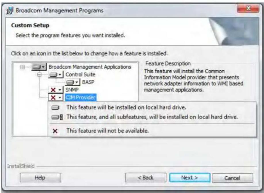
Figure 18. BACS CIM Option Window
- Select CIM Provider.
- Select one of the following:
☐ This feature will be installed on local hard drive.
☐ This feature, and all subfeatures, will be installed on local hard drive.
-
Click Next.
-
Follow the on-screen instructions to complete the installation.
The BASP version of SNMP has two components that are described in the following sections:
☐ "BASP Subagent" on page 79
☐ "BASP Extensible-Agent" on page 79
BASP Subagent The BASP subagent, baspmgnt.dll, is designed for the Windows Server 2008, Windows Server 2008 R2, and Windows Server 2012 platforms. You must install the SNMP service before installing the BASP subagent.
The BASP subagent allows an SNMP manager software to actively monitor the configuration and performance of the Broadcom Advanced Server features. The subagent also provides an alarm trap to an SNMP manager to inform the manager of any changes to the conditions of the BASP component.
The BASP subagent allows monitoring of the configurations and statistics of the BASP teams, the physical NIC adapters participating in a team, and the virtual NIC adapters created as the result of teaming. Non-teamed NIC adapters are not monitored. The BASP configuration data includes information such as team IDs, physical-virtual-VLAN-team adapter IDs, physical-virtual-VLAN-team adapter descriptions, and the MAC addresses of the adapters.
The statistics include detailed information such as data packets transmitted and received for the physical-virtual-VLAN-team adapters.
The alarm trap forwards information about the changes in configuration of the physical adapters participating in a team, such as whether or not the physical adapter link is up or down and each time the adapter is installed or removed.
To monitor this information, an SNMP manager must load the Broadcom BASP MIB database files to allow monitoring of the information described above. The following files are posted on the Allied Telesis web site:
□ baspcfg.mib
□ baspstat.mib
□ basptrap.mib
BASP The Broadcom NetXtreme II Gigabit Ethernet Controller Extended Information SNMP extensible-agent (bcmif.dll) is designed for Windows Server 2008, Windows Server 2008 R2, and Windows Server 2012 SNMP service. You must install the Windows 2000 Server SNMP service before installing the extensible-agent.
The extensible-agent allows the SNMP manager software to actively monitor the configurations of the AT-ANC10S/2 network adapter. It supplements the information already provided by the standard SNMP Management Network Interface information.
The extensible-agent provides in-depth information about the AT-ANC10S/2 network adapter including:
□ MAC address
☐ Bound IP address
□ IP subnet mask
□ Physical link status
Adapter state
□ Line speed
□ Duplex mode
□ Memory range
□ Interrupt setting
□ Bus number
□ Device number
□ Function number
To monitor this information, an SNMP manager needs to load the Broadcom Extended information MIB file to allow monitoring of the information listed above. See the following procedure.
The monitored workstation requires the installation of the Broadcom Extended Information SNMP extensible-agent, bcmif.dll, and requires the Microsoft Windows Server 2008, Windows Server 2008 R2, or Windows Server 2012 SNMP service to be installed and loaded.
Loading the SNMP Libraries
By default, the BACS utility does not load the SNMP libraries. You need to select this option.
To load the SNMP libraries on your PC, do the following:
- Download the BACS utility from the Allied Telesis website.
This utility is available from the www.alliedtelesis.com/support/software website. After accessing the website, enter the model number in the Search by Product Name box and click Find to view the current list of available files.
- Download BACS onto your PC.
- On your PC, open the InstallShield.
- Select SNMP.
The BACS SNMP Option Window is displayed. See Figure 18.
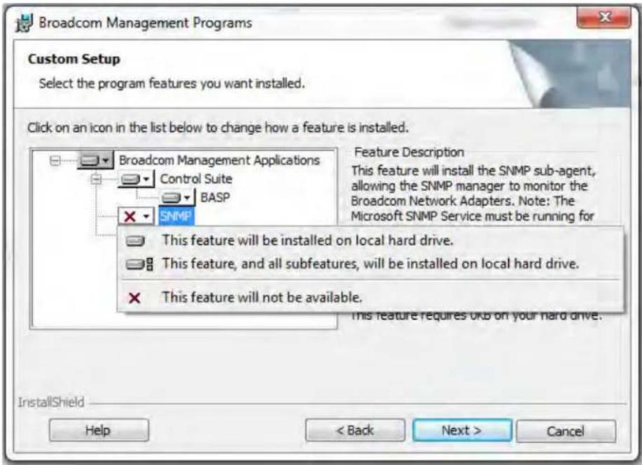
Figure 19. BACS SNMP Option Window
- Select one of the following:
☐ This feature will be installed on local hard drive.
☐ This feature, and all subfeatures, will be installed on local hard drive.
-
Click Next.
-
Follow the on screen instructions to complete the installation.
Chapter 8
Installing Management Applications
This chapter provides information about prerequisites for installing management applications as well as procedures instructions. This chapter discusses the following topics:
☐ "Installing Broadcom Advanced Control Suite 4 and Related Management Applications" on page 84
☐ “Modifying Management Applications” on page 88
☐ “Repairing Management Applications” on page 89
☐ “Removing Management Applications” on page 90
Installing Broadcom Advanced Control Suite 4 and Related Management Applications
The Broadcom Advanced Control Suite 4 (BACS 4) software and related management applications can be installed from the source-file directory or by using the silent install option. See the following:
☐ “Checking .NET Framework Requirements” on page 84
☐ "Using the Installer" on page 85
☐ "Using the Silent Install Option" on page 85
After you use the source-file directory or the silent install option, the following features are installed on your system:
☐ Control Suite - Broadcom Advanced Control Suite 4 (BACS 4).
☐ BASP - Installs Broadcom Advanced Server Program.
☐ SNMP - Installs the Simple Network Management Protocol subagent.
☐ CIM Provider - Installs the Common Information Model provider.
Note
Ensure that the Broadcom network adapter(s) is physically installed in the system before installing BACS 4.
Note
Before installing Broadcom Advance Control Suite 4, verify that .NET Framework is up to date.
Note
Before you begin the installation, close all applications, windows, or dialog boxes.
Checking .NET Framework Requirements
Before you use either the source-file directory or the silent install option, you must make sure that your system meets the minimum installation requirements.
Microsoft .NET Framework includes the runtime and associated files needed to run BACS 4, and must be installed on your system in order for BACS 4 to operate. Please be sure the .NET Framework version for your operating system is up to date.
Note
Starting BACS 4 without .NET Framework installed on your system results in an error.
Using the Installer
The driver software is available for download from the Allied Telesis web site at www.alliedtelesis.com/support. After accessing this website, enter the model number in the Search by Product Name box and then click Find to view the current list of available software drivers.
To install the management applications, do the following:
Note
Before starting the installation, verify that .NET Framework is up to date to ensure optimal performance of BACS 4.
- Open the MgmtApps folder, select IA32 or x64, and then double-click Setup.exe to open the InstallShield Wizard.
- Click Next to continue.
- After you review the license agreement, click I accept the terms in the license agreement and then click Next to continue.
- Select the features you want installed. If you receive a warning regarding .NET Framework, then press OK to continue installing BACS 4 and manually install .NET Framework when the installation is completed, or Cancel to quit.
- Click Next.
- Click Install.
- Click Finish to close the wizard.
Using the Silent Install Option
You can use the silent install option to install from a source folder or any folder. You can create a log file during the installation procedure. In addition, you can specify which features you will install on your system. See the following sections:
☐ “Performing a Silent Install from the Installer Source Folder” on page 86
☐ “Performing a Silent Install and Creating a Log File” on page 86
☐ “Performing a Silent Install from any Folder” on page 86
☐ “Performing a Silent Install by Feature on IA32 Platforms” on page 87
☐ “Performing a Silent Install by Feature on AMD64/EM64T Platforms” on page 87
☐ “Performing a Silent Install from Within a Batch File” on page 87
Note
All commands are case sensitive.
Note
User must "Run as Administrator" for Vista when using "msiexec" for "silent" install/uninstall(s).
Performing a Silent Install from the Installer Source Folder
To perform a silent install (or upgrade) from within the installer source folder, enter:
setup /s /v/qn
If performing a silent upgrade, your system may reboot automatically. To suppress the reboot, enter:
setup /s /v"/qn REBOOT=ReallySuppress"
Performing a Silent Install and Creating a Log File
To perform a silent install and create a log file, enter:
setup /s /v"/qn /L f:\ia32\1testlog.txt"
The 1testlog.txt log file is created at f:\ia32.
Performing a Silent Install from any Folder
To perform a silent uninstall from any folder on the hard drive, enter:
msiexec /x " {26E1BFB0-E87E-4696-9F89-B467F01F81E5}" /qn
Note
The hexadecimal number above may differ from your current installer. Check the Key name corresponding with the Broadcom Advanced Control Suite 4(BACS) application in HKLM\Software\Microsoft\Windows\CurrentVersion\Uninstall for the correct hexadecimal number.
Note
After performing a silent uninstall, it is necessary to reboot the system before reinstalling this installer. If you do not perform a reboot, BASP does not install correctly.
Performing a Silent Install by Feature on IA32 Platforms
To perform a silent install by feature on IA32 platforms, enter:
Note
CHM32 or CHM64 installs the BACS help file and must be included when installing the BACS feature.
Use ADDSOURCE to include any of the features listed below.
setup /s /v"/qn
ADDSOURCE=BACSi32,CHM32,BASPi32,SNMPi32,CIMi32"
Performing a Silent Install by Feature on AMD64/EM64T Platforms
To perform a silent install by feature on AMD64/EM64T platforms, enter:
setup /s /v"/qn
ADDSOURCE=BACSa64,CHMa64,BASPa64,SNMPa64"
Performing a Silent Install from Within a Batch File
To perform a silent install from within a batch file and wait for the install to complete before continuing with the next command line, enter:
start /wait setup /s /w /v/qn
Modifying Management Applications
To modify the management applications, do the following:
- In Control Panel, double-click Add or Remove Programs.
- Click Broadcom Management Programs and then click Change.
- Click Next to continue.
- Click Modify to change program features.
- Click Next to continue.
- Click on an icon to change how a feature is installed.
- Click Next.
- Click Install.
- Click Finish to close the wizard.
- Reboot your system to complete the modification of the management applications.
Repairing Management Applications
To repair or reinstall the management applications, do the following:
- In Control Panel, double-click Add or Remove Programs.
- Click Broadcom Management Programs, and then click Change.
- Click Next to continue.
- Click Repair to repair errors in installed applications.
- Click Next to continue.
- Click Install.
- Click Finish to close the wizard.
Removing Management Applications
To remove all management applications, do the following:
- In Control panel, double-click Add or Remove Programs.
- Click Broadcom Management Programs, and then click Remove.
- Reboot your system to complete the removal of the management applications.
This chapter provides troubleshooting information. It discusses the following topics:
☐ “Checking Hardware Diagnostics” on page 92
☐ "Checking Port LEDs" on page 93
☐ “Consulting the Troubleshooting Checklist” on page 94
☐ “Solving Microsoft Windows Server 2008 R2 Hyper-V Issues” on page 97
☐ “Solving Broadcom Boot Agent and Broadcom Advanced Server Program (BASP) Issues” on page 100
☐ “Solving Miscellaneous Issues” on page 102
Within the chapter there are several references to the Broadcom Advanced Control Suite 4 User Guide. You can download this manual from the Allied Telesis website at www.alliedtelesis.com/support/software. After accessing the website, enter the model number in the Search by Product Name box and then click Find to view the current list of documents.
Checking Hardware Diagnostics
Loopback diagnostic tests are available for testing the adapter hardware. These tests provide access to the adapter internal and external diagnostics, where packet information is transmitted across the physical link. For instructions and information on running tests in an MS-DOS environment, see Chapter 10, "User Diagnostics" on page 105. For Windows environments, see "Running Diagnostic Tests" in the Broadcom Advanced Control Suite 4 User Guide which you can download from the Allied Telesis website.
Checking Port LEDs
To check the state of the network links and activities on the ports, refer to Table 2 on page 20:
Consulting the Troubleshooting Checklist
Note
Before you open the cabinet of your server to add or remove the adapter, see "Reviewing Safety Precautions" on page 25.
The following checklist provides recommended actions to resolve problems installing or running the AT-ANC10S/2 adapter in your system:
☐ Inspect all cables and connections. Verify that the cable connections at the network adapter and the switch are attached properly. Verify that the cable length and rating comply with the requirements of the SFP+ transceiver.
☐ Check the adapter installation by reviewing “Installing the Network Adapter Card” on page 30. Verify that the adapter is properly seated in the slot. Check for specific hardware problems, such as obvious damage to board components or the PCI edge connector.
☐ Check the configuration settings and change them if they are in conflict with another device.
☐ Verify that your server is using the latest BIOS.
☐ Try inserting the adapter in another slot. If the new position works, the original slot in your system may be defective.
☐ Replace the failed adapter with one that is known to work properly. If the second adapter works in the slot where the first one failed, the original adapter is probably defective.
☐ Install the adapter in another functioning system and run the tests again. If the adapter passed the tests in the new system, the original system may be defective.
☐ Remove all other adapters from the system and run the tests again. If the adapter passes the tests, the other adapters may be causing contention.
Checking the Current Drivers
This section describes how to check that the current drivers are properly loaded for the Windows and Linux platforms.
Windows
See "Viewing Vital Signs" in the Broadcom Advanced Control Suite 4 User Guide to view vital information about the adapter, link status, and network connectivity.
Linux
To verify that the bnx2x.o (or bnx2x.ko) driver is loaded properly, enter:
lsmod
If the driver is loaded, a line similar to one Table 9 is displayed, where size indicates the size of the driver in bytes, and number is the number of adapters configured.
Table 9. Linux Module Size
| Module Size Used by | |
| BCM5709 size number |
Running a Cable Length Test
For a Windows operating systems, see "Analyzing Cables" in the Broadcom Advanced Control Suite 4 User Guide for information on running a cable length test.
Testing Network Connectivity
This section describes how to test network connectivity for the Windows and Linux platforms.
Note
When using forced link speeds, verify that both the adapter and the switch are forced to the same speed.
Windows
In the Windows platforms, use the ping command to test network connectivity. If the new adapter is the only adapter in the system, you may test it by having it ping another device on the network. But if the new adapter is in a system that contains more than one adapter, you instead should test it by pinging it from another device on your network.
Note
Network connectivity can also be tested using the "Testing the Network" feature in the Broadcom Advanced Control Suite 4 User Guide.
To determine if the network connection is working, do the following:
- Click Start, and then click Run.
-
Type cmd in the Open box, and then click OK.
-
If you are performing the ping command at the system where the new adapter is installed, type ipconfig /all to verify that the new adapter is operational.
-
Type ping
, and then press Enter. If you are performing the ping command at the system where the new adapter is installed, specify the IP address of a remote device the adapter is to ping. If you are performing the command at another system, enter the IP address of the new adapter.
The ping statistics that are displayed indicate whether the network connection is working or not.
Linux
To verify that the Ethernet interface is up and running on a Linux platform, run ifconfig to check the status of the Ethernet interface. In addition, you can enter the netstat -i command to check the statistics on the Ethernet interface. See "Installing Linux Driver Software" on page 41 for information on ifconfig and netstat.
If the new adapter is the only adapter in the system, you may test it by having it ping another device on the network. But if the new adapter is in a system that contains more than one adapter, you instead should test it by pinging it from another device on your network.
Ping an IP host on the network to verify connection has been established. From the command line, type ping IP address, and then press Enter.
The ping statistics that are displayed indicate whether or not the network connection is working.
Solving Microsoft Windows Server 2008 R2 Hyper-V Issues
Microsoft Windows Server 2008 R2 Hyper-V™ is a hypervisor virtualization system. For detailed information about Hyper-V, refer to the following website:
www.microsoft.com/windowsserver2008/en/us/hyperv.aspx
This section addresses issues that affect the configuration of the AT-ANC10S/2 network adapter and teamed adapters when Hyper-V is used.
Note
Ensure that Integrated Services, which is a component of Hyper-V, is installed in the guest operating system (child partition) for full functionality.
Single Network Adapter
When configuring an AT-ANC10S network adapter for Hyper-V, be aware of the following:
☐ An adapter that is bound to a virtual network should not be configured for VLAN tagging through the driver's advanced properties. Instead, Hyper-V should manage VLAN tagging exclusively.
☐ Since Hyper-V does not support Jumbo Frames, it is recommended that this feature not be used or connectivity issues may occur with the child partition.
☐ The Locally Administered Address (LAA) set by Hyper-V takes precedence over an address set in the adapter's Advanced Properties.
☐ In an IPv6 network, a team that supports Checksum Offload (CO) and Large Send Offload (LSO) and is bound to a Hyper-V virtual network reports CO and LSO as an offload capability in BACS. Also, in an IPv6 network, a team that supports CO or LSO and is bound to a Hyper-V virtual network reports CO or LSO as an offload capability in BACS. However, in both instances CO and LSO do not work. This is a limitation of Hyper-V because this system does not support CO and LSO in an IPv6 network.
Teamed Network Adapters
The following Broadcom team types are supported with Hyper-V:
☐ Smart Load Balancing and Failover (configured only for one primary and one standby)
☐ Link Aggregation (IEEE 802.3ad LACP)
☐ Generic Trunking (FEC/GEC) 802.3ad Draft Static
When configuring a team of AT-ANC10S network adapter on a Hyper-V system, be aware of the following:
☐ Create the team prior to binding the team to the Hyper-V virtual network
☐ Create a team only with an adapter that is not already assigned to a Hyper-V virtual network.
☐ In an IPv6 network, a team that supports Checksum Offload (CO) and Large Send Offload (LSO) and is bound to a Hyper-V virtual network reports CO and LSO as an offload capability in BACS. Also, in an IPv6 network, a team that supports CO or LSO and is bound to a Hyper-V virtual network reports CO or LSO as an offload capability in BACS. However, in both instances CO and LSO do not work. This is a limitation of Hyper-V because this system does not support CO and LSO in an IPv6 network.
☐ To successfully perform VLAN tagging for both the host (parent partition) and the guest (child partition) with the BASP teaming software, you must configure the team for tagging. Unlike VLAN tagging with a single adapter, tagging cannot be managed by Hyper-V when using BASP software.
Removing the Device Drivers
Uninstall the device drivers for the network adapter from your system only through the InstallShield wizard. Uninstalling the device drivers with Device Manager or any other means may not provide a clean uninstall which, in turn, may cause the system to become unstable. For information on uninstalling device drivers, see “Removing the Device Drivers” on page 57.
Preparing an Answer File
When creating an answer file for an unattended installation or for the System Preparation Tool (Sysprep) utility, you must include the following lines under the [Unattend] section:
OemPreinstall=Yes OemPnpDriversPath=Drivers\NIC
Note
This does not include an unattended installation when performed from a CD-ROM.
Note
The path shown in OemPnpDriversPath can be appended with the path to other applicable drivers.
For an unattended installation, place the driver files for the network adapter in the \OEM\\1\Drivers\NIC directory. For Sysprep, the drivers are located in Drivers\NIC at the root of the system drive. The driver files are listed below according to the operating system to be installed:
☐ Windows Server (ia32): bxvbd.inf, bxvbdx.sys, bxvbd.cat, bxnd.inf, bxnd.cat, bxnd52x.sys, bxndcox.dll, bxdiag.cat, bxdiag.inf, bxdiagx.sys, wdfcoinstaller01005.dll, and wUDFUpdate_01005.dll
☐ Windows Server (x64): bxvbd.inf, bxvbda.sys, bxvbd.cat, bxnd.inf, bxnd.cat, bxnd52a.sys, bxndcoa.dll, bxdiag.cat, bxdiag.inf, bxdiaga.sys, wdfcoinstaller01005.dll, and wUDFUpdate_01005.dll
When applying network properties through an answer file for an AT-ANC10S/2 network adapter where the PnP iD is the identifier, do the following:
For a BCM57810 Netxtreme II 10GigE - Infld = "b06bdrv\2nd&pci_168e14e4"
Currently, the PCI location (PCI bus, device, and function numbers) method is not supported for a network adapter as an identifier or a network adapter in the answer file due to a limitation with the Windows operating system.
Solving Broadcom Boot Agent and Broadcom Advanced Server Program (BASP) Issues
This section discusses issues with the Broadcom Boot Agent and Broadcom Advanced Server (BASP) as well as provides solutions.
Problem: Unable to obtain network settings through DHCP using PXE.
Solution: For proper operation, make sure that the Spanning Tree Protocol (STP) feature is disabled or that portfast mode (for Cisco switches) is enabled on the port to which the PXE client is connected. For instance, set spantree portfast 4/12 enable.
Problem: A BASP team in Windows Server 2003 may not function properly if a team member driver property is modified.
Solution: Due to a limitation in Windows Server 2003, the features of team members should remain static during the entire life of the team. To change the characteristics of a team member, remove the team member from the team, modify the team member, and then the adapter to the team again. This limitation does not exist in Windows Server 2008 or Windows Server 2008 R2.
Problem: A system containing an 802.3ad team causes a Netlogon service failure in the system event log and prevents it from communicating with the domain controller during boot up.
Solution: Microsoft Knowledge Base Article 326152 (support.microsoft.com/kb/326152/en-us) indicates that Gigabit Ethernet adapters may experience problems with connectivity to a domain controller due to link fluctuation while the driver initializes and negotiates a link with the network infrastructure. The link negotiation is further affected when the Gigabit adapters are participating in an 802.3ad team due to the additional negotiation with a switch required for this team type. As suggested in the Knowledge Base Article above, disabling media sense as described in a separate Knowledge Base Article 239924 (support.microsoft.com/kb/239924) has shown to be a valid workaround when this problem occurs.
Problem: The 802.3ad team member links disconnect and reconnect continuously (applies to all operating systems).
Solution: This is a third-party issue. It is seen only when configuring an 802.3ad team with more than two members on the server and connecting an HP2524 switch, with LACP enabled as passive or active. The HP switch shows an LACP channel being brought up successfully with only two team members. All other team member links disconnect and reconnect. This issue does not occur with the Cisco Catalyst 6500 switch.
Problem: A Generic Trunking (GEC/FEC) 802.3ad-Draft Static type of team may lose some network connectivity if the driver to a team member is disabled.
Solution: If a team member supports underlying management software (ASF/IPMI/UMP) or Wake-On-LAN, the link may be maintained on the switch for the adapter despite its driver being disabled. This may result in the switch continuing to pass traffic to the attached port rather than route the traffic to an active team member port. Disconnecting the disabled adapter from the switch allows traffic to resume to the other active team members.
Problem: Large Send Offload (LSO) and Checksum Offload are not working on my team.
Solution: If one of the adapters on a team does not support LSO, LSO does not function for the team. Remove the adapter that does not support LSO from the team or replace it with one that does. This same solution applies to Checksum Offload.
Problem: The advanced properties of a team do not change after changing the advanced properties of an adapter that is a member of the team.
Solution: If an adapter is included as a member of a team and you change any advanced property, then you must rebuild the team to ensure that the team's advanced properties are properly set.
Problem: Errors occur when an RSS-enabled adapter is included as a member of a team on a Windows Server 2008, Windows Server 2008 R2, or Windows Server 2012 system.
Solution: Disable RSS from all members of the team and rebuild the team.
Solving Miscellaneous Issues
This section presents issues and provides solutions for a variety of driver software issues.
Problem: Although installed, the Broadcom Advanced Control Suite 4 (BACS) application does not start and an error message appears.
Solution: NET Framework is required for BACS 4 to operate. Install .NET Framework.
Problem: Broadcom Advanced Control Suite 4 takes a long time to start up.
Solution: This is a limitation of .NET Framework 2.0. Apply .NET Framework 2.0 SP1 and reboot your system.
Problem: The AT-ANC10S network adapter may not perform at optimal levels on some systems if it is added after the system has booted.
Solution: The system BIOS in some systems does not set the cache line size and the latency timer if the adapter is added after the system has booted. Reboot the system after the adapter has been added.
Problem: Intelligent Platform Management Interface (IPMI) is not functioning properly.
Solution: IPMI works only when LiveLink™ is disabled. See “Configuring LiveLink for a Smart Load Balancing and Failover and SLB (Auto-Fallback Disable) Team” in the Broadcom Advanced Control Suite 4 User Guide.
Problem: Cannot configure Resource Reservations in BACS 4 after SNP is uninstalled.
Solution: Reinstall SNP. Prior to uninstalling SNP from the system, ensure that NDIS is enabled via the checkbox on the Resource Configuration screen, available from the Resource Reservations section of the Configurations tab (see Viewing Resource Reservations in the Broadcom Advanced Control Suite 4 User Guide). If NDIS is disabled and SNP is removed, there is no access to re-enable the device.
Problem: A DCOM error message (event ID 10016) appears in the System Event Log during the installation of the Broadcom adapter drivers.
Solution: This is a Microsoft issue. For more information, see Microsoft knowledge base KB913119 at support.microsoft.com/kb/913119.
Problem: Performance is degraded when multiple BCM57810 network adapters are used in a system.
Solution: Ensure that the system has at least 2 GB of main memory when using up to four network adapters and 4 GB of main memory when using four or more network adapters.
Chapter 9: Troubleshooting
This chapter provides user diagnostic information for the MS-DOS platform. This chapter discusses the following topics:
☐ "Overview" on page 106
☐ "System Requirements" on page 107
☐ "Performing Diagnostics" on page 108
☐ “Diagnostic Test Descriptions” on page 111
Overview
Broadcom NetXtreme II User Diagnostics is an MS-DOS based application that runs a series of diagnostic tests. These tests allow you to update device firmware as well as to view and change settings for available adapter properties.
Note
The diagnostics utility is available from the Allied Telesis web site at www.alliedtelesis.com/support/software.
To run Broadcom NetXtreme II User Diagnostics, you must create an MS-DOS 6.22 bootable disk containing the uediag.exe file. Next, start the system with the boot disk in drive A. See the following sections:
☐ For a list of system requirements to run the diagnostic tests, see "System Requirements" on page 107.
☐ For instructions how to run diagnostic tests on the AT-ANC10S/2 adapter, see "Performing Diagnostics" on page 108.
☐ For descriptions of the available diagnostic tests, see “Diagnostic Test Descriptions” on page 111.
System Requirements
The following system requirements are needed to run user diagnostics:
☐ MS-DOS 6.22 Operating System
□ uediag.exe file
Performing Diagnostics
At the MS-DOS prompt, type uediag followed by the command options.
The uediag command options are shown in Table 10. For example, to run all of the diagnostic tests except Group B tests on adapter #1, enter:
C:>uediag -c 1 -t b
Note
You must include uediag at the beginning of the command string each time you type a command.
Note
Not all commands are supported on all adapters.
Table 10. uediag Command Options
| Command Option Description | |
| uediag Performs all tests on all the AT-ANC10S/2 network adapters in your system. | |
| uediag -c Specifies the adapter (devnum) to test. Use all in place of a specific device number to test all adapters. | |
| uediag -cof Allows tests to continue after detecting a failure. | |
| uediag -F Forces an upgrade de of the image without checking the version. | |
| uediag -fbc $ specifies the bin file to update the bootcode. | |
| uediag -fipmi <ipmi_image> | Specifies the bin file to update IPMI firmware. |
| uediag -fmba <mba_image> | Specifies the bin file to update the MBA. |
| uediag -fncsi <ncsi_image> | Specifies the bin file to update the NCSI firmware. |
| uediag -fnvm <raw_image> | Programs the raw image into NVM. |
| Command Option | Description |
| uediag -fump | Specifies the bin file to update the UMP firmware. |
| uediag -help Displays the | Broadcom NetXtreme IIUser Diagnostics, uediag, command options. |
| uediag -l | Specifies the number of iterations to run on the selected tests. |
| uediag -idmatch Enables | matching of VID, DID, SVID,and SSID from the image file with device IDs. Used only with -fnvm. |
| uediag -log Logs the test results to a specified log file. | |
| uediag -mba <1/0> Enables/disables Multiple Boot Agent (MBA) protocol where:1 = Enable0 = Disable | |
| uediag -mbap Sets the MBA boot protocol, where:0 = PXE1 = RPL2 = BOOTP | |
| uediag -mbas Sets the MBA/PXE speed, where:0 = Auto1 = 10H2 = 10F3 = 100H4 = 100F6 = 1000F | |
| uediag -mbav <1|0> Enables/disables MBA VLAN, where:1 = Enable0 = Disable | |
| uediag -mbavval Sets MBA VLAN (<65536). | |
| uediag -mfw <1/0> Enables/disables management firmware, where:1 = Enable0 = Disable | |
| uediag -tDisables certain groups or tests. | |
| uediag -TEnables certain groups or tests. | |
| Command Option Description | |
| uediag -ver Displays the version of BroadcomNetXtreme II User Diagnostics(uediag) and all installed adapters. | |
| uediag -wol <1/0> Enables/disables Magic Packet WOLwhere:1 = Enable0 = DisableWOL is not supported on 10GbpsEthernet adapters. | |
Diagnostic Test Descriptions
The diagnostic tests are divided into four groups:
☐ Basic Functional Tests (Group A)
☐ Memory Tests (Group B)
□ Block Tests (Group C)
☐ Ethernet Traffic Tests (Group D).
The diagnostic tests are described in Table 11.
Table 11. Diagnostic Tests
| Test | Description | |
| Number Name | ||
| Group A: Basic Functional Tests | ||
| A1 Register Verifies that registers accessible through the PCI/PCI-E interface implement the expected read-only or read/write attributes by attempting to modify those registers. | ||
| A2 PCI Configuration Checks the functionality of the PCI Base Address Register (BAR) by varying the amount of memory requested by the BAR and verifying that the BAR actually requests the correct amount of memory (without actually mapping the BAR into system memory). Refer to PCI or PCI-E specifications for details on the BAR and its addressing space. | ||
| A3 Interrupt Generates a PCI interrupt and verifies that the system receives the interrupt and invokes the correct ISR. A negative test is also performed to verify that a masked interrupt does not invoke the ISR. | ||
| A5 MSI Verifies that a Message Signalled Interrupt (MSI) causes an MSI message to be DMA'd to host memory. A negative test is also performed to verify that when an MSI is masked, it does not write an MSI message to host memory. | ||
| A6 Memory BIST Invokes the internal chip Built-In Self Test (BIST) command to test internal memory. | ||
| Group B: Memory Tests | ||
| B1 TXP Scratchpad | The Group B tests verify all of the memory blocks of the network adapters by writing various data patterns (0x55aa55aa, 0xaa55aa55, walking zeroes, walking ones, address, etc.) to each memory location, reading back the data, and then comparing it to the value written. The fixed data patterns are used to ensure that no memory bit is stuck high or low, while the walking zeroes/ones and address tests are used to ensure that memory writes do not corrupt adjacent memory locations. | |
| B2 TPAT Scratchpad | ||
| B3 RXP Scratchpad | ||
| B4 COM Scratchpad | ||
| B5 CP Scratchpad | ||
| B6 MCP Scratchpad | ||
| B7 TAS Header | Buffer | |
| B8 TAS Payload | Buffer | |
| B9 RBUF via GRC | ||
| B10 RBUF via Indirect Access | ||
| B11 RBUF Cluster List | ||
| B12 TSCH List | ||
| B13 CSCH List | ||
| B14 RV2P Scratchpads | ||
| B15 TBDC Memory | ||
| B16 | RBDC | Memory |
| B17 CTX Page Table | ||
| B18 | CTX | Memory |
Group C: Block Tests
| C1 CPU Logic and DMA Interface | Verifies the basic logic functionality of all the on-chip CPUs. It also exercises the DMA interface exposed to those CPUs. The internal CPU tries to initiate DMA activities (both read and write) to system memory and then compares the values to confirm that the DMA operation completed successfully. | |
| Test | Description | |
| Number Name | ||
| C2 RBUF Allocation | Verifies the RX buffer (RBUF) allocation interface by allocating and releasing buffers and checking that the RBUF block maintains an accurate count of the allocated and free buffers. | |
| C3 CAM Access | Verifies the content-addressable memory (CAM) block by performing read, write, add, modify, and cache hit tests on the CAM associative memory. | |
| C4 TPAT Cracker | Verifies the packet cracking logic block (that is, the ability to parse TCP, IP, and UDP headers within an Ethernet frame) as well as the checksum/CRC offload logic. In this test, packets are submitted to the chip as if they were received over Ethernet and the TPAT block cracks the frame (identifying the TCP, IP, and UDP header data structures) and calculates the checksum/CRC. The TPAT block results are compared with the values expected by Broadcom NetXtreme II User Diagnostics and any errors are displayed. | |
| C5 FIO Register | The Fast IO (FIO) verifies the register interface that is exposed to the internal CPUs. | |
| C6 NVM Access | and Reset-Corruption | Verifies non-volatile memory (NVM) accesses (both read and write) initiated by one of the internal CPUs. It tests for appropriate access arbitration among multiple entities (CPUs). It also checks for possible NVM corruption by issuing a chip reset while the NVM block is servicing data. |
| C7 | Core-Reset Integrity | Verifies that the chip performs its reset operation correctly by resetting the chip multiple times, checking that the bootcode and the internal uediag driver loads/unloads correctly. |
| C8 DMA Engine | Verifies the functionality of the DMA engineblock by performing numerous DMA read and write operations to various system and internal memory locations (and byte boundaries) with varying lengths (from 1 byte to over 4 KB, crossing the physical page boundary) and different data patterns (incremental, fixed, and random). CRC checks are performed to ensure data integrity. The DMA write test also verifies that DMA writes do not corrupt the neighboring host memory. | |
| C9 VPD Exercises | the Vital Product Data (VPD)interface using PCI configuration cycles. You must program a proper bootcode into the non-volatile memory. If no VPD data is present (that is, the VPD NVM area is all 0s), the test first initializes the VPD data area with non-zero data before starting the test and restores the original data after the test completes. | |
| C11 FIO Events | Verifies that the event bits in the CPU's FastIO (FIO) interface are triggering correctly when a particular chip events occur, such as a VPD request initiated by the host, an expansion ROM request initiated by the host, a timer event generated internally, toggling any GPIO bits, or accessing NVM. | |
Group D: Ethernet Traffic Tests
| D1 MAC Loopback Enables MAC loopback mode in the adapter and transmits 5000 Layer 2 packets of various sizes. As the packets are received by Broadcom NetXtreme II User Diagnostics, they are checked for errors. Packets are returned through the MAC receive path and never reach the PHY. The adapter should not be connected to a network. |
Table 11. Diagnostic Tests (Continued)
| Test | Description | |
| Number Name | ||
| D2 PHY Loopback Enables PHY loopback mode in the adapter and transmits 5000 Layer 2 packets of various sizes. As the packets are received by Broadcom NetXtreme II User Diagnostics, they are checked for errors. Packets are returned through the PHY receive path and never reach the wire. The adapter should not be connected to a network. | ||
| D4 LSO Verifies the functionality of the adapter's Large Send Offload (LSO) support by enabling MAC loopback mode and transmitting large TCP packets. As the packets are received by Broadcom NetXtreme II User Diagnostics, they are checked for proper segmentation (according to the selected MSS size) and any other errors. The adapter should not be connected to a network. | ||
| D5 EMAC Statistics Verifies that the basic statistics information maintained by the chip is correct by enabling MAC loopback mode and sending Layer 2 packets of various sizes. The adapter should not be connected to a network. | ||
| D6 RPC Verifies the Receive Path Catch-up (RPC) block by sending packets to different transmit chains. The packets traverse the RPC logic (though not the entire MAC block) and return to the receive buffers as received packets. This is another loopback path that is used by Layer 4 and Layer 5 traffic within the MAC block. As packets are received by Broadcom NetXtreme II User Diagnostics, they are checked for errors. The adapter should not be connected to a network | ||
Chapter 10: User Diagnostics
Appendix A
Technical Specifications
This appendix contains the following sections:
□ "Physical Specifications"
☐ "Environmental Specifications"
☐ "Power Specifications" on page 118
☐ "Performance Specification" on page 118
Physical Specifications
Table 12 contains the dimensions and weight of the adapter card.
Table 12. AT-ANC10S/2 Physical Specifications
| Dimensions 160.0 mm (6.3 in) x 68.9 mm (2.7 in) | |
| Weight 78.0 g (2.8 oz) | |
Environmental Specifications
Table 13 contains the environmental specifications of the adapter card.
Table 13. Environmental Specifications
| Environmental Specification Value | |
| Operating Temperature 0°C to 50°C | C (32°F to 122°F) |
| Storage Temperature -25°C to 70°C | C (-13°F to 158°F) |
| Operating Humidity 5% to 95% non-condensing | |
| Storage Humidity 5% to 95% non-condensing | |
| Maximum Operating Altitude Up to 3,048 m (10,000 ft) | |
| Maximum Storage Altitude Up to 3,048 m (10,000 ft) | |
Power Specifications
Table 14 contains the power specifications of the adapter card:
Table 14. Operating Voltages and Maximum Power Consumption
| Operating Voltage 3.3V and 12V | |
| Maximum Power Consumption 6W |
Performance Specification
The adapter card is x8 PCIe v2.0 and v1.1 compliant
The fiber optic connector consists of a fiber optic plug and its adapter. The end of the fiber optic cable is held in the core of the ferrule in the plug. Light signals are transmitted through the core of the fiber. Even minor smudges or dirt on the end face of the fiber, completely invisible to the naked eye, can disrupt light transmission and lead to failure of the component or of the entire system. Therefore, it is of utmost importance to clean all fiber optic connectors before use.
Figure 20 shows the ferrule in an SC connector.
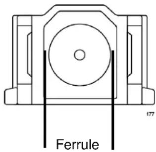
Figure 20. Ferrule in an SC Connector Plug
Figure 21 shows part of the end face of an unclean and clean ferrule.

Unclean Clean
Figure 21. Unclean and Clean Ferrule
This appendix provides the following procedures
☐ "Using a Cartridge-Type Cleaner" on page 120
☐ "Using a Swab" on page 122
Using a Cartridge-Type Cleaner
Fiber optic cartridge cleaners are available from many vendors and are typically called “cartridge cleaners.” An example is shown in Figure 22.
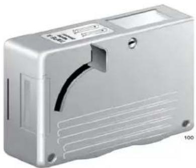
natural_image
Exterior view of a silver rectangular electronic device casing with ventilation slots and a curved cutout (no text or symbols visible)Figure 22. Cartridge Cleaner
Note
Do not use compressed air or aerosol air to clean a fiber optic connector.
To clean a fiber optic connector using a cartridge cleaner, perform the following procedure.
-
With one hand, hold the cartridge cleaner and push the lever on the cleaning cartridge in the direction of the arrow to expose the cleaning surface, as shown in Figure 23.
-
Place the ferrule tip on the exposed cleaning surface and rub the ferrule in a downward direction, as shown in Figure 23.
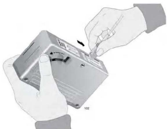
natural_image
Illustration of hands installing or adjusting a device component with a 102-degree angle indicator (no text or symbols on the device itself)Figure 23. Rubbing the Ferrule Tip on the Cleaning Surface
Note
Rub the ferrule tip on the cleaning surface in one direction only.
- When you reach the end of the cleaning surface, pick up the ferrule tip, rotate and place it at the top and rub downwards at least 2 times.

Caution
Failing to pick up the ferrule tip when you reach the bottom of the cleaning surface can result in static electricity that can damage the fiber optic cable. E82
-
If desired, repeat steps 3 and 4.
-
If a fiber inspection scope is available, use the scope to inspect the ferrule end face to make sure that it is clean.
-
Reconnect the cable to the port or protect the ferrule tip with a dust cap.
Note
Always keep a dust cap on a fiber optic cable when it is not in use.
Note
Do not touch the end face of the ferrule in the connector.

Warning
Do not stare into the laser beam. L2

Warning
Do not look directly at the cable ends or inspect the cable ends with an optical lens. E29
Using a Swab
Specially treated swabs, known as stick cleaners, are available for cleaning inside connector adapters or hard-to-reach ferrule tips. These swabs, often referred to as "lint free" or "alcohol free" swabs, are available from many vendors. Examples are shown in Figure 24. Stick cleaners are available in both 2.5 mm and 1.25 mm sizes for use on SC and MU connectors respectively.
Note
NEVER use a household cotton swab and/or alcohol to clean a fiber optic connector. This may leave a residue on the ferrule tip.
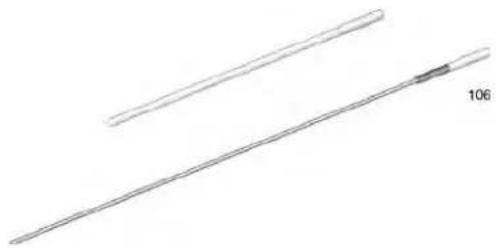
natural_image
Two elongated, thin lines with a small arrowhead labeled '106' (no other text or symbols)Figure 24. Lint-Free and Alcohol-Free Swabs
Note
Do not use compressed air or aerosol air to clean a fiber optic connector.
To clean a recessed ferrule using a swab, perform the following procedure.
- Insert the swab into the adapter as shown in Figure 23 and rub the ferrule tip with the swab.
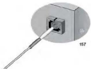
natural_image
Close-up of a mechanical component with a probe inserted into a square opening, labeled '157' (no text or symbols on the object itself)Figure 25. Cleaning a Recessed Ferrule
-
If desired, repeat step 1.
-
If a fiber inspection scope is available, use the scope to inspect the connector to make sure that it is clean and to check for scratches, pits, or other problems that may affect performance.
Note
Always keep a dust cap on a fiber optic cable when it is not in use.

Warning
Do not stare into the laser beam. ∞ L2

Warning
Do not look directly at the cable ends or inspect the cable ends with an optical lens. E29

- Installation and User's Guide
- Federal Communications Commission Interference Statement
- Declaration of Conformity
- IMPORTANT NOTE:
- FCC Radiation Exposure Statement:
- Industry Canada
- European Union Restriction of the Use of Certain Hazardous Substances (RoHS) in Electrical and Electronic Equipment
- Translated Safety Statements
- Contents
- Preface 13
- Chapter 1: Introducing the AT-ANC10S/2 Adapter .....17
- Chapter 2: Installing the Hardware ....23
- Chapter 3: Installing Broadcom Boot Agent Driver Software ....35
- Chapter 4: Installing the Linux Drivers ....39
- Chapter 5: Installing the Windows Drivers ....47
- Chapter 6: Setting Advanced Properties ...... 59
- Chapter 7: Installing CIM and SNMP for Manageability .... 75
- Chapter 8: Installing Management Applications .... 83
- Chapter 9: Troubleshooting 91
- Chapter 10: User Diagnostics .... 105
- Appendix A: Technical Specifications 117
- Appendix B: Cleaning Fiber Optic Connectors 119
- Figures
- Tables
- Safety Symbols Used in this Document
- Note
- Caution
- Warning
- Contacting Allied Telesis
- Chapter 1
- Introducing the AT-ANC10S/2 Adapter
- Functional Descriptions
- AT-ANC10S/2 Adapter Physical Description
- Features
- Adaptive Interrupt Frequency
- ASIC with Embedded RISC Processor
- Supported Operating Environments
- Chapter 2
- Installing the Hardware
- Reviewing the Contents of Your Shipment
- Reviewing Safety Precautions
- Pre-Installation Checklist
- Installing the Standard Bracket on the Adapter
- Installing the Network Adapter Card
- Figure 9. Securing the Adapter with a High-profile Bracket
- Installing SFP+ Transceivers in the AT-ANC10S/2 Adapter
- Chapter 3
- Installing Broadcom Boot Agent Driver Software
- Overview
- Setting Up MBA in a Client Environment
- Setting Up the BIOS
- Setting Up MBA in a Server Environment: Red Hat Linux PXE Server
- Chapter 4
- Installing the Linux Drivers
- bnx2x Driver Limitations
- Packaging
- Installing Linux Driver Software
- Installing the Source RPM Package
- Building the Driver from the Source TAR File
- Building the bnx2x Driver
- Unloading the Linux Driver
- Unloading the Driver from an RPM Installation
- Unloading the Driver from a TAR Installation
- Patching PCI Files (Optional)
- Network Installations
- Setting Optional Properties for the bnx2x Driver
- Checking the bnx2x Driver Defaults
- Checking Driver Messages
- Teaming with Channel Bonding
- Chapter 5
- Installing the Windows Drivers
- Supported Versions of Microsoft Windows
- Installing the Windows Driver Software
- Using the Installer
- Click Install.
- Using Silent Installation
- Performing a Silent Install
- Performing a Silent Install and Creating a Log File
- Performing a Silent Upgrade
- Performing a Silent Uninstall
- Performing a Silent Reinstall
- Removing the Device Drivers
- Chapter 6
- Setting Advanced Properties
- Advanced Features
- Accessing the Advanced Tab
- Selecting the Advanced Tab in Windows Server 2012
- Modifying the Advanced Properties
- Chapter 7
- Installing CIM and SNMP for Manageability
- Installing CIM
- Loading the CIM Libraries
- Loading the SNMP Libraries
- Chapter 8
- Installing Management Applications
- Installing Broadcom Advanced Control Suite 4 and Related Management Applications
- Checking .NET Framework Requirements
- Using the Silent Install Option
- Performing a Silent Install from the Installer Source Folder
- Performing a Silent Install from any Folder
- Performing a Silent Install by Feature on IA32 Platforms
- Performing a Silent Install by Feature on AMD64/EM64T Platforms
- Performing a Silent Install from Within a Batch File
- Modifying Management Applications
- Repairing Management Applications
- Removing Management Applications
- Checking Hardware Diagnostics
- Checking Port LEDs
- Consulting the Troubleshooting Checklist
- Checking the Current Drivers
- Windows
- Linux
- Running a Cable Length Test
- Testing Network Connectivity
- Solving Microsoft Windows Server 2008 R2 Hyper-V Issues
- Single Network Adapter
- Teamed Network Adapters
- Preparing an Answer File
- Solving Broadcom Boot Agent and Broadcom Advanced Server Program (BASP) Issues
- Solving Miscellaneous Issues
- System Requirements
- Performing Diagnostics
- Diagnostic Test Descriptions
- Appendix A
- Technical Specifications
- Physical Specifications
- Environmental Specifications
- Power Specifications
- Performance Specification
- Using a Cartridge-Type Cleaner
- Using a Swab
Brand : Allied Telesis
Model : AT-ANC10S/2
Category : Network card / adapter